JP2012002425A - Plate type heat exchanger, and heat pump device - Google Patents
Plate type heat exchanger, and heat pump device Download PDFInfo
- Publication number
- JP2012002425A JP2012002425A JP2010137506A JP2010137506A JP2012002425A JP 2012002425 A JP2012002425 A JP 2012002425A JP 2010137506 A JP2010137506 A JP 2010137506A JP 2010137506 A JP2010137506 A JP 2010137506A JP 2012002425 A JP2012002425 A JP 2012002425A
- Authority
- JP
- Japan
- Prior art keywords
- flow path
- plate
- fluid
- heat exchanger
- heat
- Prior art date
- Legal status (The legal status is an assumption and is not a legal conclusion. Google has not performed a legal analysis and makes no representation as to the accuracy of the status listed.)
- Granted
Links
Images


Abstract
Description
この発明は、複数の伝熱プレートを積層して形成されたプレート式熱交換器に関する。 The present invention relates to a plate heat exchanger formed by laminating a plurality of heat transfer plates.
従来のプレート式熱交換器は、伝熱プレート間に形成される流路の一部が、流体の流出入口近傍で閉塞されている(特許文献1参照)。
また、プレート式熱交換器内で流体がよどみ、プレート式熱交換器内で流体が凍結することを回避するため、流体の流出入口の位置を変更したプレート式熱交換器がある(特許文献2参照)。
In a conventional plate heat exchanger, a part of a flow path formed between heat transfer plates is closed in the vicinity of a fluid outflow inlet (see Patent Document 1).
Further, there is a plate heat exchanger in which the position of the fluid inlet / outlet is changed in order to avoid fluid stagnation in the plate heat exchanger and freezing of the fluid in the plate heat exchanger (Patent Document 2). reference).
従来、プレート式熱交換器内を流れる流体は、流出入口と短軸方向逆側の領域に流れづらく、その領域でよどみを生じやすい。例えば、プレート式熱交換器が水と冷媒とを熱交換させる蒸発器として使われる場合、水側の流路で前述のよどみが発生すると、その領域での水温度が周囲に比べ急速に低下する。その結果、その領域で水が凍結し、熱交換器が破損してしまう。
この対策として、特許文献2では、流出入口の位置を変更し、流出入口の近傍の水がよどむ領域に閉塞部を設け、よどみを防止している。しかし、閉塞部は水が流れず伝熱面積が減少し熱交換性能の低下を生じる。
この発明は、伝熱面積を減少させること無く、プレート式熱交換器内における流体のよどみの発生を防止することを目的とする。
Conventionally, the fluid flowing in the plate heat exchanger is difficult to flow in the region opposite to the outflow inlet and the short axis direction, and stagnation is likely to occur in that region. For example, when a plate heat exchanger is used as an evaporator for exchanging heat between water and a refrigerant, if the stagnation occurs in the flow path on the water side, the water temperature in that region rapidly decreases compared to the surroundings. . As a result, water freezes in the area, and the heat exchanger is damaged.
As a countermeasure, in
An object of the present invention is to prevent the occurrence of fluid stagnation in a plate heat exchanger without reducing the heat transfer area.
この発明に係るプレート式熱交換器は、
第1流体又は第2流体の流出入口となる通路孔が四隅に設けられた複数の矩形のプレートが積層され、各プレートの間に前記第1流体が流れる第1流路と前記第2流体が流れる第2流路とが交互に形成されたプレート式熱交換器であり、
前記第1流路は、前記各プレートの長軸方向の一方側に設けられた通路孔である流入口から流入した前記第1流体を、前記長軸方向の他方側に設けられた通路孔である流出口から流出させる流路であって、前記流入口と前記流出口との間に、前記第1流体を隣接する第2流路を流れる前記第2流体と熱交換させる熱交換流路が形成された流路であり、
前記第1流路には、前記長軸方向の前記一方側に設けられた通路孔であって前記流入口とは異なるもう1つの通路孔である上流側隣接孔と、前記上流側隣接孔が位置するプレートのコーナーとの間の領域を通して、前記流入口から流入した前記第1流体の一部を前記熱交換流路へバイパスさせる上流側バイパス流路が形成された
ことを特徴とする。
The plate heat exchanger according to the present invention is
A plurality of rectangular plates with passage holes serving as outflow inlets of the first fluid or the second fluid provided at the four corners are stacked, and the first flow path through which the first fluid flows and the second fluid flow between the plates. It is a plate type heat exchanger in which the flowing second flow paths are alternately formed,
The first flow path is a passage hole provided on the other side in the long axis direction for the first fluid that has flowed in from an inflow port that is a passage hole provided on one side in the long axis direction of each plate. A flow path for flowing out from a certain outlet, and a heat exchange path for exchanging heat between the first fluid and the second fluid flowing in the adjacent second path between the inlet and the outlet. Formed flow path,
The first flow path includes an upstream adjacent hole which is a passage hole provided on the one side in the long axis direction and is different from the inflow port, and the upstream adjacent hole. An upstream bypass flow path that bypasses a part of the first fluid that has flowed in from the inflow port to the heat exchange flow path is formed through a region between the corners of the plate located.
この発明に係るプレート式熱交換器は、バイパス流路から短軸方向の流入口とは逆側の熱交換流路へ第1流体が流入する。そのため、第1流体のよどみが発生することを防止できる。 In the plate heat exchanger according to the present invention, the first fluid flows from the bypass channel into the heat exchange channel on the side opposite to the inflow port in the short axis direction. Therefore, it is possible to prevent the stagnation of the first fluid.
実施の形態1.
実施の形態1に係るプレート式熱交換器30の基本構成を説明する。
図1は、プレート式熱交換器30の側面図である。図2は、補強用サイドプレート1の正面図(積層方向から見た図)である。図3は、伝熱プレート2の正面図である。図4は、伝熱プレート3の正面図である。図5は、補強用サイドプレート4の正面図である。図6は、伝熱プレート2と伝熱プレート3とを積層した状態を示す図である。図7は、プレート式熱交換器30の分解斜視図である。図8は、伝熱プレート2の形状の説明図である。図9は、伝熱プレート3の形状の説明図である。
Embodiment 1 FIG.
A basic configuration of the
FIG. 1 is a side view of the
図1に示すように、プレート式熱交換器30は、伝熱プレート2と伝熱プレート3とが交互に積層される。また、プレート式熱交換器30は、最前面に補強用サイドプレート1が積層され、最背面に補強用サイドプレート4が積層される。
As shown in FIG. 1, in the
図2に示すように、補強用サイドプレート1は、略矩形の板状に形成される。補強用サイドプレート1は、略矩形の四隅に、第1流入管5、第1流出管6、第2流入管7、第2流出管8が設けられる。
図3,4に示すように、各伝熱プレート2,3は、補強用サイドプレート1と同様に、略矩形の板状に形成され、四隅に第1流入口9、第1流出口10、第2流入口11、第2流出口12が設けられる。また、各伝熱プレート2,3は、プレートの積層方向に変位する波形状15,16であって、積層方向から見た場合に略V字状に形成された波形状15,16が形成される。特に、伝熱プレート2に形成された波形状15と、伝熱プレート3に形成された波形状16とでは、略V字状の向きが逆向きになっている。
図5に示すように、補強用サイドプレート4は、補強用サイドプレート1等と同様に、略矩形の板状に形成される。補強用サイドプレート4は、第1流入管5、第1流出管6、第2流入管7、第2流出管8が設けられない。なお、図5では、補強用サイドプレート4に、第1流入管5、第1流出管6、第2流入管7、第2流出管8の位置を破線で示すが、補強用サイドプレート4にこれらが設けられているわけではない。
As shown in FIG. 2, the reinforcing side plate 1 is formed in a substantially rectangular plate shape. The reinforcing side plate 1 is provided with a
As shown in FIGS. 3 and 4, each
As shown in FIG. 5, the reinforcing side plate 4 is formed in a substantially rectangular plate shape, like the reinforcing side plate 1 and the like. The reinforcing side plate 4 is not provided with the
図6に示すように、伝熱プレート2と伝熱プレート3とを積層した場合、向きの異なる略V字状の波形状15,16が重なり合うことにより、伝熱プレート2と伝熱プレート3との間に複雑な流れを引き起こす流路が形成される。
As shown in FIG. 6, when the
図7に示すように、各伝熱プレート2,3は、第1流入口9同士、第1流出口10同士、第2流入口11同士、第2流出口12同士がそれぞれ重なるように積層される。また、補強用サイドプレート1と伝熱プレート2とは、第1流入管5と第1流入口9とが重なり、第1流出管6と第1流出口10とが重なり、第2流入管7と第2流入口11とが重なり、第2流出管8と第2流出口12とが重なるように積層される。そして、各伝熱プレート2,3及び補強用サイドプレート1,4の外周の縁が重なるように積層され、ロウ等により接合される。この際、各伝熱プレート2,3は、外周の縁が接合されるだけでなく、積層方向から見た場合に、上側のプレートの波形状の底と下側のプレートの波形状頂とが重なる部分も接合される。
As shown in FIG. 7, the
これにより、第1流入管5から流入した第1流体(例えば、水)が第1流出管6から流出する第1流路13が、伝熱プレート3の背面と伝熱プレート2の前面との間に形成される。同様に、第2流入管7から流入した第2流体(例えば、冷媒)が第2流出管8から流出する第2流路14が、伝熱プレート2の背面と伝熱プレート3の前面との間に形成される。
外部から第1流入管5へ流入した第1流体は、各伝熱プレート2,3の第1流入口9が重なり合うことで形成された通路孔を流れ、各第1流路13へ流入する。第1流路13へ流入した第1流体は、短軸方向へ徐々に広がりながら、長軸方向へ流れて、第1流出口10から流出する。第1流出口10から流出した第1流体は、第1流出口10が重なり合うことで形成された通路孔を流れ、第1流出管6から外部へ流出する。
同様に、外部から第2流入管7へ流入した第2流体は、各伝熱プレート2,3の第2流入口11が重なり合うことで形成された通路孔を流れ、各第2流路14へ流入する。第2流路14へ流入した第2流体は、短軸方向へ徐々に広がりながら、長軸方向へ流れて、第2流出口12から流出する。第2流出口12から流出した第2流体は、第2流出口12が重なり合うことで形成された通路孔を流れ、第2流出管8から外部へ流出する。
第1流路13を流れる第1流体と第2流路14を流れる第2流体とは、波形状15,16が形成された部分を流れる際、伝熱プレート2,3を介して熱交換される。なお、第1流路13と第2流路14とにおいて、波形状15,16が形成された部分を熱交換流路17(図3,4,6参照)と呼ぶ。
Accordingly, the
The first fluid that has flowed into the
Similarly, the second fluid that has flowed into the second inflow pipe 7 from the outside flows through the passage holes formed by overlapping the
The first fluid flowing in the
図8に示すように、伝熱プレート2の第1流入口9及び第1流出口10の周囲のハッチング部分18は、波形状15の底と同程度の高さである。一方、伝熱プレート2の第2流入口11及び第2流出口12の周囲のハッチング部分19は、波形状15の頂と同程度の高さである。
同様に、図9に示すように、伝熱プレート3の第1流入口9及び第1流出口10の周囲のハッチング部分20は、波形状16の頂と同程度の高さである。一方、伝熱プレート3の第2流入口11及び第2流出口12の周囲のハッチング部分21は、波形状16の底と同程度の高さである。
そして、伝熱プレート2と伝熱プレート3とが交互に積層された場合、伝熱プレート3の背面側と伝熱プレート2の前面側とでは、伝熱プレート3のハッチング部分21と、伝熱プレート2のハッチング部分19とが密着する。一方、伝熱プレート3のハッチング部分20と、伝熱プレート2のハッチング部分18との間には空間ができる。したがって、第1流入口9を流れる第1流体は、伝熱プレート3の背面側と伝熱プレート2の前面側との間に形成された第1流路13へ流入するが、第2流入口11を流れる第2流体は、第1流路13へ流入しない。また、第1流路13を流れる第1流体が第2流入口11や第2流出口12へ流出することもない。
同様に、伝熱プレート2の背面側と伝熱プレート3の前面側とでは、伝熱プレート2のハッチング部分18と、伝熱プレート3のハッチング部分20とが密着する。一方、伝熱プレート2のハッチング部分19と、伝熱プレート3のハッチング部分21との間には空間ができる。したがって、第2流入口11を流れる第2流体は、伝熱プレート2の背面側と伝熱プレート3の前面側との間に形成された第2流路14へ流入するが、第1流入口9を流れる第1流体は、第2流路14へ流入しない。また、第2流路14を流れる第2流体が第1流入口9や第1流出口10へ流出することもない。
As shown in FIG. 8, the hatched
Similarly, as shown in FIG. 9, the hatched
And when the heat-
Similarly, the hatched
第1流路13では、付近のハッチング部分19とハッチング部分21とが密着し、その部分の流路が閉塞された状態となる。そのため、第1流路13の熱交換流路17における第2流入口11付近及び第2流出口12付近(図7の破線部分25)は、第1流体が流れづらく、よどみ易い部分となる。
同様に、第2流路14では、ハッチング部分18とハッチング部分20とが密着し、その部分の流路が閉塞された状態となる。そのため、第2流路14の熱交換流路17における第1流入口9付近及び第1流出口10付近(図7の破線部分26)は、第2流体が流れづらく、よどみ易い部分となる。
In the
Similarly, in the
次に、実施の形態1に係るプレート式熱交換器30の特徴について説明する。実施の形態1に係るプレート式熱交換器30は、第1流路13に第2流出口12(上流側隣接孔)とプレートのコーナーとの間の流路を通るバイパス流路22(上流側バイパス流路)を設けたことが特徴である。
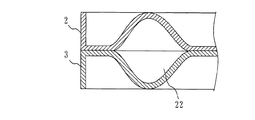
図10は、実施の形態1に係る伝熱プレート2の正面図である。図11は、伝熱プレート2と伝熱プレート3とを積層した状態における図10のA−A部分断面を示す図である。
Next, features of the
FIG. 10 is a front view of the
図10、図11に示すように、第1流路13には、通常のプレート式熱交換器では閉塞されている部分に、バイパス流路22が設けられている。バイパス流路22は、プレートの積層方向の一方側から見た場合に、第1流入口9から流入した第1流体を、第2流出口12とプレートの短辺との間を通し、第2流出口12とプレートの長辺との間を通して、熱交換流路17の短軸方向における第2流出口12側の端へ流入させる。
したがって、第1流入口9から第1流路13へ流入した第1流体は、通常のプレート式熱交換器と同様に、主流入流路23から熱交換流路17へ流入するだけでなく、バイパス流路22から熱交換流路17へ流入する。上述したように、主流入流路23から熱交換流路17へ第1流体が流入しただけでは、熱交換流路17における第2流出口12付近へは、第1流体が流れづらく、よどんでしまう。しかし、バイパス流路22を設けることにより、熱交換流路17における第2流出口12付近へ第1流体を流すことが可能となり、よどみが発生することを防止できる。
As shown in FIGS. 10 and 11, the
Therefore, the first fluid that has flowed into the
例えば、第1流体が水であり、第2流体が冷媒であり、プレート式熱交換器30が蒸発器として機能する場合、第1流路13内で水が滞留すると、滞留した水が冷媒により急激に冷却される。その結果、水が凍結し、体積膨張によりプレート式熱交換器30が破損する虞がある。しかし、実施の形態1に係るプレート式熱交換器30では、第1流路13内で水が滞留しないため、プレート式熱交換器30が破損することを防止できる。
For example, when the first fluid is water, the second fluid is a refrigerant, and the
また、従来第1流体がよどんでいた部分は、有効に熱交換されていなかった。しかし、実施の形態1に係るプレート式熱交換器30では、従来第1流体がよどんでいた部分のよどみが解消され、有効な熱交換面積が増加する。さらに、バイパス流路22においても熱交換されるため、有効な熱交換面積が増加する。したがって、熱交換効率がよくなる。そのため、プレート式熱交換器30は、蒸発器としてだけではなく、凝縮器として用いてもよい。
また、プレート式熱交換器30を空気調和機に用いる場合、プレート式熱交換器30の熱交換性能が向上したことにより、空気調和機の必要能力に対するプレート式熱交換器30の必要プレート枚数を減らすことができる。また、上述したように、プレート式熱交換器30内の凍結を防止でき、破損を防止できる。したがって、コストを抑えつつ、信頼性の高いプレート式熱交換器30を提供できる。
Further, the portion where the first fluid has been stagnant conventionally has not been effectively heat exchanged. However, in the
Further, when the
また、バイパス流路22は、円形の第2流出口12の周縁に沿って、滑らかに曲がって第1流入口9の近傍と熱交換流路17とを接続する。そのため、バイパス流路22を第1流体が流れることによる圧力損失を小さくすることができる。
The
なお、上記説明では、第1流路13の第1流入口9側に、第2流出口12とプレートのコーナーとの間の領域を通るバイパス流路22を設けることを説明した。しかし、これに限らず、第1流路13の第1流出口10側に、第2流入口11(下流側隣接孔)とプレートのコーナーとの間の領域を通るバイパス流路(下流側バイパス流路)を設けてもよい。
また、同様に、第2流路14の第2流入口11側にも、第1流出口10とプレートの端との間を通るバイパス流路を設けてもよいし、第2流出口12側にも、第1流入口9とプレートの端との間を通るバイパス流路を設けてもよい。
In the above description, it has been described that the
Similarly, a bypass channel that passes between the
実施の形態2.
実施の形態2では、バイパス流路22の流路断面積を一定にしたプレート式熱交換器30について説明する。
図12は、実施の形態2に係る伝熱プレート2の正面図である。図13は、実施の形態2に係る伝熱プレート3の正面図である。図14は、図12に示す伝熱プレート2と図3に示す伝熱プレート3とを積層した場合における図12と図13とのB−B断面図である。
In the second embodiment, a
FIG. 12 is a front view of the
図12と図13とに示すように、伝熱プレート2と伝熱プレート3とは、積層された場合に、積層方向にちょうど重なる位置にバイパス流路22が形成されている。図14に示すように、伝熱プレート2はバイパス流路22部分が凸状になっており、伝熱プレート3はバイパス流路22部分が凹状になっている。そして、伝熱プレート2の凸状部と、伝熱プレート3の凹状部とが重なることで、バイパス流路22が形成されている。伝熱プレート2における凸状部の中空部分についての第1流体の流れる方向と垂直方向における断面積は一定であり、伝熱プレート3の凹状部の中空部分についての第1流体の流れる方向と垂直方向における断面積も一定である。したがって、バイパス流路22の流路断面積(第1流体の流れる方向と垂直方向の断面積)は一定である。
バイパス流路22の流路断面積が一定であるため、バイパス流路22におけるゴミ詰まりやよどみが発生しづらい。また、バイパス流路22を形成する凸状部分、凹状部分を、波形状の頂や底と同様に、隣接するプレートの凸状部分、凹状部分と接合させることができるため、プレート式熱交換器30の強度が高くなる。
As shown in FIGS. 12 and 13, when the
Since the channel cross-sectional area of the
なお、上記説明では、伝熱プレート2に形成された凸状部分と、伝熱プレート3に形成された凹状部分とが積層方向に重なってバイパス流路22が形成されると説明した。しかし、伝熱プレート2と伝熱プレート3とのいずれか一方を平らにして、バイパス流路22の流路断面積を小さくしてもよい。
In the above description, it has been described that the convex portion formed on the
実施の形態3.
実施の形態3では、バイパス流路22が波形状15又は波形状16の1つの波と滑らかな曲線で繋がったプレート式熱交換器30について説明する。
図15は、実施の形態3に係る伝熱プレート2の正面図である。
In the third embodiment, a
FIG. 15 is a front view of the
図15に示すように、伝熱プレート2に形成されたバイパス流路22が、波形状15の稜線と平行な方向に滑らかに曲がって、波形状15の1つの波の端に接続している。
そのため、バイパス流路22を流れる第1流体が波形状15によって形成される流路へ流入する際の圧力損失を低減できる。また、バイパス流路22から波形状15によって形成される流路への流れ込みが滑らかになり、第1流路13内の短軸方向の速度分布が均一になるため、第1流路13全体の圧力損失が低減する。第1流路13内の短軸方向の速度分布が均一になることで、第1流路13内でのゴミ詰まりやよどみが発生しづらく、熱交換効率が向上する。
As shown in FIG. 15, the
Therefore, the pressure loss when the first fluid flowing through the
実施の形態4.
実施の形態4では、バイパス流路22の入口側(第1流入口9側)と、出口側(熱交換流路17側)とが複数に分岐されたプレート式熱交換器30について説明する。
図16は、実施の形態4に係るプレート式熱交換器30の説明図である。
Embodiment 4 FIG.
In the fourth embodiment, a plate
FIG. 16 is an explanatory diagram of the
図16に示すように、バイパス流路22は、入口側が複数の流路で形成され、途中で1本の流路に合流して、再び出口側が複数の流路に分岐する。
そのため、バイパス流路22の入口付近や出口付近の流路断面積が大きくなり、圧力損失を低減できる。また、分岐した流路の一部がゴミやスラッジで閉塞しても、他の流路が利用可能であるため、バイパス流路22の閉塞による熱交換性能低下や破損を防止できる。
また、出口側の流路を分岐させることにより、第1流体を短軸方向の広い範囲へ流出させることができる。したがって、よどみが生じ易い部分の分布に応じて分岐された出口側の流路の方向や、分岐数を調整すれば、流速分布を均一化できる。なお、分岐した出口側の流路をそれぞれ、波形状15の稜線と平行な方向に滑らかに曲げて、波の端に接続するようにしてもよい。なお、出口側の分岐に伴う流路の広がり角度(図16の角度C)は、最大180度とする。
As shown in FIG. 16, the
For this reason, the cross-sectional area of the flow path near the inlet or the outlet of the
In addition, the first fluid can flow out to a wide range in the minor axis direction by branching the outlet-side flow path. Therefore, the flow velocity distribution can be made uniform by adjusting the direction of the outlet-side flow path branched according to the distribution of the portion where stagnation is likely to occur and the number of branches. Note that the branched outlet-side flow paths may be smoothly bent in the direction parallel to the ridgeline of the
実施の形態5.
実施の形態5では、第1流入口9の主流入流路23(図10参照)側に堰24を設けたプレート式熱交換器30について説明する。
図17は、実施の形態5に係る伝熱プレート2と伝熱プレート3とを積層した状態の斜視図である。図18は、図17のD−Dの第1流入口9側半分の伝熱プレート2を取り除いた状態を示す斜視図である。
In the fifth embodiment, a
FIG. 17 is a perspective view of a state in which the
図17と図18とに示すように、第1流路13には、第1流入口9の主流入流路23側を覆うように、第1流入口9の縁に沿って第1流体の流れを妨げる板状の堰24が設けられている。堰24は、第1流入口9の円周の高々半分を覆うように、最大で半円状に形成される。
バイパス流路22を設けたことにより、第1流入口9から流入した第1流体が流れ出す流路断面積が増加するため、熱交換流路17を流れる第1流体の流速が遅くなってしまう。そのため、熱伝達率が低下してしまう。そこで、堰24を設けることにより、第1流入口9から流入した第1流体が主流入流路23側へ流れることが妨げ、主流入流路23を流れる第1流体の流速を速くする。その結果、熱交換流路17を流れる第1流体の流速が速くなり、熱伝達率を改善することができる。
堰24が塞ぐ面積を拡大すると流速は速くなり、堰24が塞ぐ面積を縮小すると流速は遅くなる。そこで、例えば、バイパス流路22の流路断面積と同じ面積を塞ぐ堰24を設けると、流速はバイパス流路22がない場合と同等になり、熱伝達率を維持したまま有効伝熱面積を増加できる。
As shown in FIGS. 17 and 18, the first fluid flows along the edge of the
By providing the
When the area covered by the
なお、堰24は、図17、図18に示す形状に限らず、他の形状であってもよい。図19から図22は、堰24の他の形状を示す図である。なお、図19から図22は、第1流入口9側半分の伝熱プレート2を取り除いた状態を示す。
例えば、図19に示すように、堰24は、図17、図18に示す堰24に孔を開け、堰24が塞ぐ面積を調整したものであってもよい。
また、図20に示すように、第1流入口9の主流入流路23側に、複数の直方体状のブロックを堰24として並べてもよい。
また、図21に示すように、第1流入口9の主流入流路23側に、複数の円柱や楕円柱状のブロックを堰24として並べてもよい。
また、図22に示すように、波形状15,16の一部を変形して、第1流入口9の主流入流路23側を塞ぐようにして、堰24を構成してもよい。
The
For example, as shown in FIG. 19, the
In addition, as shown in FIG. 20, a plurality of rectangular parallelepiped blocks may be arranged as
In addition, as shown in FIG. 21, a plurality of cylindrical or elliptical blocks may be arranged as
In addition, as shown in FIG. 22, the
また、上記説明では、第1流入口9側、つまり上流側に堰24を設けた。しかし、第1流出口10側、つまり下流側に堰24を設けてもよい。
In the above description, the
堰24は、プレスによるバーリング加工で作成すると製造コストを安価にできる。
If the
実施の形態6.
実施の形態6では、バイパス流路22と主流入流路23との流路断面積比について説明する。
図23は、バイパス流路22と主流入流路23との流路断面積比と、熱通過率及び流速比率との関係を示す図である。図23では、横軸が「主流入流路23の断面積/バイパス流路22の断面積」の値であり、縦軸が熱通過率及び流速比率である。なお、熱通過率及び流速比率は、バイパス流路22を設けていない場合を基準(1.00)とする。
In the sixth embodiment, the ratio of the channel cross-sectional area between the
FIG. 23 is a diagram illustrating the relationship between the flow path cross-sectional area ratio between the
上述したように、バイパス流路22を設けることにより、第1流路13を流れる第1流体の流速が遅くなり、熱通過率が低下してしまう。しかし、熱通過率の低下が5%以内であれば、有効伝熱面積の増加分で、熱通過率の低下による熱交換量の低下分を十分に補える。
ここで、図23に示すように、主流入流路23の流路断面積がバイパス流路22の流路断面積の8倍以上である場合、熱通過率の低下が5%以内となる。そこで、主流入流路23の流路断面積がバイパス流路22の流路断面積の8倍以上とするのがよい。
As described above, by providing the
Here, as shown in FIG. 23, when the flow passage cross-sectional area of the main
実施の形態7.
実施の形態7では、以上の実施の形態で説明したプレート式熱交換器30の活用例であるヒートポンプ式暖房給湯システム110について説明する。
Embodiment 7 FIG.
In the seventh embodiment, a heat pump heating and hot water supply system 110 that is an example of utilization of the
図24は、実施の形態7に係るヒートポンプ式暖房給湯システム110の構成を示す概略図である。
ヒートポンプ式暖房給湯システム110は、圧縮機111、第1熱交換器112、第1膨張弁113、第2熱交換器114を順次接続する主冷媒回路116と、第1熱交換器112、暖房給湯用水利用装置115を順次接続する水回路117とを備える。
ここで、第1熱交換器112は、以上の実施の形態で説明したプレート式熱交換器30である。また、圧縮機111、第1熱交換器112、第1膨張弁113、第2熱交換器114、及びこれらを順次接続する主冷媒回路116は、ユニット内に収納され、これをヒートポンプ装置118と呼ぶ。
FIG. 24 is a schematic diagram showing a configuration of a heat pump heating / hot water supply system 110 according to the seventh embodiment.
The heat pump heating / hot water supply system 110 includes a main
Here, the
第1熱交換器112では、圧縮機111が圧縮した冷媒と、水回路117を流れる流体(ここでは、水)とを熱交換する。ここでは、第1熱交換器112において熱交換されることにより、冷媒が冷され、水が温められる。第1膨張弁113は、第1熱交換器112で熱交換された冷媒を膨張させる。第2熱交換器114では、第1膨張弁113の制御に従い膨張した冷媒と空気との熱交換を行う。ここでは、第2熱交換器114において熱交換されることにより、冷媒が暖められ、空気が冷やされる。そして、温められた冷媒は、圧縮機111へ吸入される。
一方、水回路117では、上述したように、第1熱交換器112で熱交換されることにより水は温められ、温められた水は暖房給湯用水利用装置115へ流れて、給湯や暖房に利用される。
In the
On the other hand, in the
以上の実施の形態で説明したように、プレート式熱交換器30は、熱交換効率がよく、信頼性が高い。したがって、本実施の形態で説明したヒートポンプ式暖房給湯システム110にプレート式熱交換器30を搭載すると、効率がよく消費電力量が抑えられCO2排出量を低減できるヒートポンプ式暖房給湯システムを実現できる。
なお、ここでは、以上の実施の形態で説明したプレート式熱交換器30で冷媒と水とを熱交換させるヒートポンプ式暖房給湯システムについて説明した。しかし、これに限らず、以上の実施の形態で説明したプレート式熱交換器30は、発電、食品の加熱殺菌処理機器等多くの産業、家庭用機器に利用可能である。
As described in the above embodiment, the
Here, the heat pump type heating hot water supply system that exchanges heat between the refrigerant and water in the
1,4 補強用サイドプレート、2,3 伝熱プレート、5 第1流入管、6 第1流出管、7 第2流入管、8 第2流出管、9 第1流入口、10 第1流出口、11 第2流入口、12 第2流出口、13 第1流路、14 第2流路、15,16 波形状、17 熱交換流路、18,19,20,21 ハッチング部分、22 バイパス流路、23 主流入流路、24 堰、25,26 破線部分、30 プレート式熱交換器。 1, 4 Reinforcement side plate, 2, 3 Heat transfer plate, 5 First inflow pipe, 6 First outflow pipe, 7 Second inflow pipe, 8 Second outflow pipe, 9 First inflow port, 10 First outflow port , 11 2nd inlet, 12 2nd outlet, 13 1st flow path, 14 2nd flow path, 15, 16 Wave shape, 17 Heat exchange flow path, 18, 19, 20, 21 Hatching part, 22 Bypass flow Road, 23 main inflow channel, 24 weir, 25, 26 broken line part, 30 plate heat exchanger.
Claims (10)
前記第1流路は、前記各プレートの長軸方向の一方側に設けられた通路孔である流入口から流入した前記第1流体を、前記長軸方向の他方側に設けられた通路孔である流出口から流出させる流路であって、前記流入口と前記流出口との間に、前記第1流体を隣接する第2流路を流れる前記第2流体と熱交換させる熱交換流路が形成された流路であり、
前記第1流路には、前記長軸方向の前記一方側に設けられた通路孔であって前記流入口とは異なるもう1つの通路孔である上流側隣接孔と、前記上流側隣接孔が位置するプレートのコーナーとの間の領域を通して、前記流入口から流入した前記第1流体の一部を前記熱交換流路へバイパスさせる上流側バイパス流路が形成された
ことを特徴とするプレート式熱交換器。 A plurality of rectangular plates with passage holes serving as outflow inlets of the first fluid or the second fluid provided at the four corners are stacked, and the first flow path through which the first fluid flows and the second fluid flow between the plates. It is a plate type heat exchanger in which the flowing second flow paths are alternately formed,
The first flow path is a passage hole provided on the other side in the long axis direction for the first fluid that has flowed in from an inflow port that is a passage hole provided on one side in the long axis direction of each plate. A flow path for flowing out from a certain outlet, and a heat exchange path for exchanging heat between the first fluid and the second fluid flowing in the adjacent second path between the inlet and the outlet. Formed flow path,
The first flow path includes an upstream adjacent hole which is a passage hole provided on the one side in the long axis direction and is different from the inflow port, and the upstream adjacent hole. A plate type characterized in that an upstream bypass flow path is formed for bypassing a part of the first fluid flowing in from the inflow port to the heat exchange flow path through a region between the corners of the plate located. Heat exchanger.
ことを特徴とする請求項1に記載のプレート式熱交換器。 The plate-type heat exchanger according to claim 1, wherein the upstream bypass flow path is formed along a peripheral edge of the upstream adjacent hole.
ことを特徴とする請求項1又は2に記載のプレート式熱交換器。 The first flow path has a downstream adjacent hole which is a passage hole provided on the other side in the major axis direction and is different from the outflow port, and the downstream adjacent hole. The downstream bypass flow path for bypassing a part of the first fluid flowing through the heat exchange flow path to the outlet is formed through a region between the corners of the plate located. Or the plate type heat exchanger of 3.
ことを特徴とする請求項3に記載のプレート式熱交換器。 The plate heat exchanger according to claim 3, wherein at least one of the upstream bypass flow path and the downstream bypass flow path has a constant flow path cross-sectional area.
前記上流側バイパス流路と前記下流側バイパス流路との少なくともいずれかは、プレートの積層方向の一方側から見た場合において、前記第1流路を形成する2つのプレートのうちの一方のプレートに形成された前記波形状の稜線と平行方向へ滑らかに曲がって、前記熱交換流路に接続された
ことを特徴とする請求項1から4までのいずれかに記載のプレート式熱交換器。 Each of the plates is formed with a wave shape that is displaced in the stacking direction in a portion that forms the heat exchange flow path.
At least one of the upstream bypass flow path and the downstream bypass flow path is one of the two plates forming the first flow path when viewed from one side in the plate stacking direction. The plate-type heat exchanger according to any one of claims 1 to 4, wherein the plate-type heat exchanger is smoothly bent in a direction parallel to the wavy ridgeline formed on the surface and connected to the heat exchange flow path.
ことを特徴とする請求項1から5までのいずれかに記載のプレート式熱交換器。 6. The upstream bypass flow path is characterized in that the inlet side branches into a plurality of flow paths, and the heat exchange flow path side branches into a plurality of flow paths. Plate heat exchanger.
ことを特徴とする請求項1から6までのいずれかに記載のプレート式熱交換器。 7. The downstream bypass flow path according to claim 1, wherein the heat exchange flow path side branches into a plurality of flow paths and the outlet side branches into a plurality of flow paths. Plate heat exchanger.
ことを特徴とする請求項1から7までのいずれかに記載のプレート式熱交換器。 The first flow path prevents the first fluid flowing out from the inlet from flowing into the heat exchange path and flows into the heat exchange path on the heat exchange path side of the inlet. The plate heat exchanger according to any one of claims 1 to 7, further comprising a weir for adjusting a flow rate of the first fluid.
ことを特徴とする請求項1から8までのいずれかに記載のプレート式熱交換器。 The upstream bypass channel has a channel cross-sectional area at a predetermined position that is 1/8 or less of the cross-sectional area in the minor axis direction of the main inflow channel connecting the inlet and the heat exchange channel. The plate heat exchanger according to any one of claims 1 to 8, wherein
前記冷媒回路に接続された前記第1熱交換器は、
第1流体又は第2流体の流出入口となる通路孔が四隅に設けられた複数の矩形のプレートが積層され、各プレートの間に前記第1流体が流れる第1流路と前記第2流体が流れる第2流路とが交互に形成されたプレート式熱交換器であり、
前記第1流路は、前記各プレートの長軸方向の一方側に設けられた通路孔である流入口から流入した前記第1流体を、前記長軸方向の他方側に設けられた通路孔である流出口から流出させる流路であって、前記流入口と前記流出口との間に、前記第1流体を隣接する第2流路を流れる前記第2流体と熱交換させる熱交換流路が形成された流路であり、
前記第1流路には、前記長軸方向の前記一方側に設けられた通路孔であって前記流入口とは異なるもう1つの通路孔である上流側隣接孔と、前記上流側隣接孔が位置するプレートのコーナーとの間の領域を通して、前記流入口から流入した前記第1流体の一部を前記熱交換流路へバイパスさせる上流側バイパス流路が形成された
ことを特徴とするヒートポンプ装置。 Comprising a refrigerant circuit in which a compressor, a first heat exchanger, an expansion mechanism, and a second heat exchanger are connected by piping;
The first heat exchanger connected to the refrigerant circuit is
A plurality of rectangular plates with passage holes serving as outflow inlets of the first fluid or the second fluid provided at the four corners are stacked, and the first flow path through which the first fluid flows and the second fluid flow between the plates. It is a plate type heat exchanger in which the flowing second flow paths are alternately formed,
The first flow path is a passage hole provided on the other side in the long axis direction for the first fluid that has flowed in from an inflow port that is a passage hole provided on one side in the long axis direction of each plate. A flow path for flowing out from a certain outlet, and a heat exchange path for exchanging heat between the first fluid and the second fluid flowing in the adjacent second path between the inlet and the outlet. Formed flow path,
The first flow path includes an upstream adjacent hole which is a passage hole provided on the one side in the long axis direction and is different from the inflow port, and the upstream adjacent hole. A heat pump device characterized in that an upstream bypass passage is formed for bypassing a part of the first fluid flowing in from the inlet to the heat exchange passage through a region between the corners of the plate located. .
Priority Applications (1)
| Application Number | Priority Date | Filing Date | Title |
|---|---|---|---|
| JP2010137506A JP5819592B2 (en) | 2010-06-16 | 2010-06-16 | Plate heat exchanger and heat pump device |
Applications Claiming Priority (1)
| Application Number | Priority Date | Filing Date | Title |
|---|---|---|---|
| JP2010137506A JP5819592B2 (en) | 2010-06-16 | 2010-06-16 | Plate heat exchanger and heat pump device |
Publications (2)
| Publication Number | Publication Date |
|---|---|
| JP2012002425A true JP2012002425A (en) | 2012-01-05 |
| JP5819592B2 JP5819592B2 (en) | 2015-11-24 |
Family
ID=45534620
Family Applications (1)
| Application Number | Title | Priority Date | Filing Date |
|---|---|---|---|
| JP2010137506A Active JP5819592B2 (en) | 2010-06-16 | 2010-06-16 | Plate heat exchanger and heat pump device |
Country Status (1)
| Country | Link |
|---|---|
| JP (1) | JP5819592B2 (en) |
Cited By (7)
| Publication number | Priority date | Publication date | Assignee | Title |
|---|---|---|---|---|
| JP2013155983A (en) * | 2012-01-31 | 2013-08-15 | Noritz Corp | Plate-type heat exchanger and water heating system including the same |
| WO2014103436A1 (en) | 2012-12-27 | 2014-07-03 | 三菱電機株式会社 | Refrigeration cycle device |
| JPWO2014147804A1 (en) * | 2013-03-22 | 2017-02-16 | 三菱電機株式会社 | Plate heat exchanger and refrigeration cycle apparatus equipped with the same |
| WO2017138322A1 (en) * | 2016-02-12 | 2017-08-17 | 三菱電機株式会社 | Plate-type heat exchanger and heat-pump-type heating and hot-water supply system equipped with same |
| CN112212726A (en) * | 2019-07-10 | 2021-01-12 | 马勒国际有限公司 | Stacked plate heat exchanger |
| CN113557404A (en) * | 2019-03-18 | 2021-10-26 | 三菱电机株式会社 | Plate heat exchanger and heat pump device provided with same |
| WO2022215415A1 (en) * | 2021-04-08 | 2022-10-13 | 株式会社デンソー | Heat exchanger |
Families Citing this family (1)
| Publication number | Priority date | Publication date | Assignee | Title |
|---|---|---|---|---|
| CN111288824B (en) * | 2018-12-06 | 2021-08-03 | 丹佛斯有限公司 | Plate heat exchanger |
Citations (8)
| Publication number | Priority date | Publication date | Assignee | Title |
|---|---|---|---|---|
| JPS61500626A (en) * | 1983-12-08 | 1986-04-03 | アルフア−ラヴアル サ−マル ア−ベ− | Plate of plate type heat exchanger |
| JPH0517369U (en) * | 1991-07-24 | 1993-03-05 | 石川島播磨重工業株式会社 | Plate fin heat exchanger |
| JPH10288479A (en) * | 1997-04-15 | 1998-10-27 | Daikin Ind Ltd | Heat exchanger |
| JPH1137677A (en) * | 1997-07-16 | 1999-02-12 | Daikin Ind Ltd | Plate type heat exchanger |
| JPH11193998A (en) * | 1997-12-26 | 1999-07-21 | Toyo Radiator Co Ltd | Multiple-plate-type heat exchanger |
| JP2007514124A (en) * | 2003-12-10 | 2007-05-31 | スウェップ インターナショナル アクティエボラーグ | Plate heat exchanger |
| JP2007205634A (en) * | 2006-02-01 | 2007-08-16 | Hisaka Works Ltd | Plate type heat exchanger |
| WO2009013801A1 (en) * | 2007-07-23 | 2009-01-29 | Tokyo Roki Co. Ltd. | Plate laminate type heat exchanger |
-
2010
- 2010-06-16 JP JP2010137506A patent/JP5819592B2/en active Active
Patent Citations (8)
| Publication number | Priority date | Publication date | Assignee | Title |
|---|---|---|---|---|
| JPS61500626A (en) * | 1983-12-08 | 1986-04-03 | アルフア−ラヴアル サ−マル ア−ベ− | Plate of plate type heat exchanger |
| JPH0517369U (en) * | 1991-07-24 | 1993-03-05 | 石川島播磨重工業株式会社 | Plate fin heat exchanger |
| JPH10288479A (en) * | 1997-04-15 | 1998-10-27 | Daikin Ind Ltd | Heat exchanger |
| JPH1137677A (en) * | 1997-07-16 | 1999-02-12 | Daikin Ind Ltd | Plate type heat exchanger |
| JPH11193998A (en) * | 1997-12-26 | 1999-07-21 | Toyo Radiator Co Ltd | Multiple-plate-type heat exchanger |
| JP2007514124A (en) * | 2003-12-10 | 2007-05-31 | スウェップ インターナショナル アクティエボラーグ | Plate heat exchanger |
| JP2007205634A (en) * | 2006-02-01 | 2007-08-16 | Hisaka Works Ltd | Plate type heat exchanger |
| WO2009013801A1 (en) * | 2007-07-23 | 2009-01-29 | Tokyo Roki Co. Ltd. | Plate laminate type heat exchanger |
Cited By (10)
| Publication number | Priority date | Publication date | Assignee | Title |
|---|---|---|---|---|
| JP2013155983A (en) * | 2012-01-31 | 2013-08-15 | Noritz Corp | Plate-type heat exchanger and water heating system including the same |
| WO2014103436A1 (en) | 2012-12-27 | 2014-07-03 | 三菱電機株式会社 | Refrigeration cycle device |
| JPWO2014147804A1 (en) * | 2013-03-22 | 2017-02-16 | 三菱電機株式会社 | Plate heat exchanger and refrigeration cycle apparatus equipped with the same |
| WO2017138322A1 (en) * | 2016-02-12 | 2017-08-17 | 三菱電機株式会社 | Plate-type heat exchanger and heat-pump-type heating and hot-water supply system equipped with same |
| US10907906B2 (en) | 2016-02-12 | 2021-02-02 | Mitsubishi Electric Corporation | Plate heat exchanger and heat pump heating and hot water supply system including the plate heat exchanger |
| CN113557404A (en) * | 2019-03-18 | 2021-10-26 | 三菱电机株式会社 | Plate heat exchanger and heat pump device provided with same |
| CN112212726A (en) * | 2019-07-10 | 2021-01-12 | 马勒国际有限公司 | Stacked plate heat exchanger |
| DE102019210238A1 (en) * | 2019-07-10 | 2021-01-14 | Mahle International Gmbh | Stacked plate heat exchanger |
| US11486658B2 (en) * | 2019-07-10 | 2022-11-01 | Mahle International Gmbh | Stacked plate heat exchanger |
| WO2022215415A1 (en) * | 2021-04-08 | 2022-10-13 | 株式会社デンソー | Heat exchanger |
Also Published As
| Publication number | Publication date |
|---|---|
| JP5819592B2 (en) | 2015-11-24 |
Similar Documents
| Publication | Publication Date | Title |
|---|---|---|
| JP5819592B2 (en) | Plate heat exchanger and heat pump device | |
| JP5661119B2 (en) | Plate heat exchanger and heat pump device | |
| CN108603732B (en) | Plate heat exchanger and heat pump type heating and hot water supply system provided with plate heat exchanger | |
| JP6641544B1 (en) | Plate heat exchanger and heat pump device provided with the same | |
| EP2410278B1 (en) | Plate-type heat exchanger and refrigerating air-conditioning device | |
| JP5805189B2 (en) | Plate heat exchanger and heat pump device | |
| US10161687B2 (en) | Plate heat exchanger and heat pump outdoor unit | |
| CN108369072B (en) | Heat exchanger and refrigeration cycle device | |
| JP6177459B1 (en) | Plate heat exchanger and refrigeration cycle equipment | |
| WO2013076751A1 (en) | Plate-type heat exchanger and refrigeration cycle device using same | |
| JP6554182B2 (en) | Heat exchanger having a plurality of stacked plates | |
| JP5414502B2 (en) | Plate heat exchanger and heat pump device | |
| JP5046748B2 (en) | Gas cooler for hot water system | |
| JP3423981B2 (en) | Heat exchangers and refrigeration air conditioners | |
| JP6450596B2 (en) | Plate heat exchanger and refrigeration cycle apparatus | |
| JP6601380B2 (en) | Heat exchanger and air conditioner | |
| JP6146966B2 (en) | Cold / hot water heat source machine | |
| JPWO2015128900A1 (en) | Heat transfer device | |
| JP2007303762A (en) | Heating and cooling system | |
| CN115143668A (en) | Heat exchanger | |
| JP2017203589A (en) | Air heat source type heat pump unit | |
| JP2003161592A (en) | Lamination type heat exchanger and air conditioner having the same | |
| JP2015068621A (en) | Water heat exchanger |
Legal Events
| Date | Code | Title | Description |
|---|---|---|---|
| A621 | Written request for application examination |
Free format text: JAPANESE INTERMEDIATE CODE: A621 Effective date: 20120731 |
|
| A977 | Report on retrieval |
Free format text: JAPANESE INTERMEDIATE CODE: A971007 Effective date: 20130711 |
|
| A131 | Notification of reasons for refusal |
Free format text: JAPANESE INTERMEDIATE CODE: A131 Effective date: 20130723 |
|
| A521 | Request for written amendment filed |
Free format text: JAPANESE INTERMEDIATE CODE: A523 Effective date: 20130902 |
|
| A02 | Decision of refusal |
Free format text: JAPANESE INTERMEDIATE CODE: A02 Effective date: 20140204 |
|
| A521 | Request for written amendment filed |
Free format text: JAPANESE INTERMEDIATE CODE: A523 Effective date: 20150729 |
|
| A61 | First payment of annual fees (during grant procedure) |
Free format text: JAPANESE INTERMEDIATE CODE: A61 Effective date: 20151001 |
|
| R150 | Certificate of patent or registration of utility model |
Ref document number: 5819592 Country of ref document: JP Free format text: JAPANESE INTERMEDIATE CODE: R150 |
|
| R250 | Receipt of annual fees |
Free format text: JAPANESE INTERMEDIATE CODE: R250 |
|
| R250 | Receipt of annual fees |
Free format text: JAPANESE INTERMEDIATE CODE: R250 |
|
| R250 | Receipt of annual fees |
Free format text: JAPANESE INTERMEDIATE CODE: R250 |
|
| R250 | Receipt of annual fees |
Free format text: JAPANESE INTERMEDIATE CODE: R250 |
|
| R250 | Receipt of annual fees |
Free format text: JAPANESE INTERMEDIATE CODE: R250 |
|
| R250 | Receipt of annual fees |
Free format text: JAPANESE INTERMEDIATE CODE: R250 |