WO2014068842A1 - Refrigerant evaporation device - Google Patents
Refrigerant evaporation device Download PDFInfo
- Publication number
- WO2014068842A1 WO2014068842A1 PCT/JP2013/005703 JP2013005703W WO2014068842A1 WO 2014068842 A1 WO2014068842 A1 WO 2014068842A1 JP 2013005703 W JP2013005703 W JP 2013005703W WO 2014068842 A1 WO2014068842 A1 WO 2014068842A1
- Authority
- WO
- WIPO (PCT)
- Prior art keywords
- refrigerant
- tank
- core
- tubes
- section
- Prior art date
Links
Images


Classifications
-
- F—MECHANICAL ENGINEERING; LIGHTING; HEATING; WEAPONS; BLASTING
- F25—REFRIGERATION OR COOLING; COMBINED HEATING AND REFRIGERATION SYSTEMS; HEAT PUMP SYSTEMS; MANUFACTURE OR STORAGE OF ICE; LIQUEFACTION SOLIDIFICATION OF GASES
- F25B—REFRIGERATION MACHINES, PLANTS OR SYSTEMS; COMBINED HEATING AND REFRIGERATION SYSTEMS; HEAT PUMP SYSTEMS
- F25B39/00—Evaporators; Condensers
- F25B39/02—Evaporators
- F25B39/028—Evaporators having distributing means
-
- F—MECHANICAL ENGINEERING; LIGHTING; HEATING; WEAPONS; BLASTING
- F28—HEAT EXCHANGE IN GENERAL
- F28D—HEAT-EXCHANGE APPARATUS, NOT PROVIDED FOR IN ANOTHER SUBCLASS, IN WHICH THE HEAT-EXCHANGE MEDIA DO NOT COME INTO DIRECT CONTACT
- F28D1/00—Heat-exchange apparatus having stationary conduit assemblies for one heat-exchange medium only, the media being in contact with different sides of the conduit wall, in which the other heat-exchange medium is a large body of fluid, e.g. domestic or motor car radiators
- F28D1/02—Heat-exchange apparatus having stationary conduit assemblies for one heat-exchange medium only, the media being in contact with different sides of the conduit wall, in which the other heat-exchange medium is a large body of fluid, e.g. domestic or motor car radiators with heat-exchange conduits immersed in the body of fluid
- F28D1/04—Heat-exchange apparatus having stationary conduit assemblies for one heat-exchange medium only, the media being in contact with different sides of the conduit wall, in which the other heat-exchange medium is a large body of fluid, e.g. domestic or motor car radiators with heat-exchange conduits immersed in the body of fluid with tubular conduits
- F28D1/053—Heat-exchange apparatus having stationary conduit assemblies for one heat-exchange medium only, the media being in contact with different sides of the conduit wall, in which the other heat-exchange medium is a large body of fluid, e.g. domestic or motor car radiators with heat-exchange conduits immersed in the body of fluid with tubular conduits the conduits being straight
- F28D1/0535—Heat-exchange apparatus having stationary conduit assemblies for one heat-exchange medium only, the media being in contact with different sides of the conduit wall, in which the other heat-exchange medium is a large body of fluid, e.g. domestic or motor car radiators with heat-exchange conduits immersed in the body of fluid with tubular conduits the conduits being straight the conduits having a non-circular cross-section
- F28D1/05366—Assemblies of conduits connected to common headers, e.g. core type radiators
- F28D1/05391—Assemblies of conduits connected to common headers, e.g. core type radiators with multiple rows of conduits or with multi-channel conduits combined with a particular flow pattern, e.g. multi-row multi-stage radiators
-
- F—MECHANICAL ENGINEERING; LIGHTING; HEATING; WEAPONS; BLASTING
- F28—HEAT EXCHANGE IN GENERAL
- F28F—DETAILS OF HEAT-EXCHANGE AND HEAT-TRANSFER APPARATUS, OF GENERAL APPLICATION
- F28F9/00—Casings; Header boxes; Auxiliary supports for elements; Auxiliary members within casings
- F28F9/02—Header boxes; End plates
- F28F9/026—Header boxes; End plates with static flow control means, e.g. with means for uniformly distributing heat exchange media into conduits
- F28F9/027—Header boxes; End plates with static flow control means, e.g. with means for uniformly distributing heat exchange media into conduits in the form of distribution pipes
- F28F9/0273—Header boxes; End plates with static flow control means, e.g. with means for uniformly distributing heat exchange media into conduits in the form of distribution pipes with multiple holes
-
- F—MECHANICAL ENGINEERING; LIGHTING; HEATING; WEAPONS; BLASTING
- F28—HEAT EXCHANGE IN GENERAL
- F28F—DETAILS OF HEAT-EXCHANGE AND HEAT-TRANSFER APPARATUS, OF GENERAL APPLICATION
- F28F9/00—Casings; Header boxes; Auxiliary supports for elements; Auxiliary members within casings
- F28F9/02—Header boxes; End plates
- F28F9/026—Header boxes; End plates with static flow control means, e.g. with means for uniformly distributing heat exchange media into conduits
- F28F9/028—Header boxes; End plates with static flow control means, e.g. with means for uniformly distributing heat exchange media into conduits by using inserts for modifying the pattern of flow inside the header box, e.g. by using flow restrictors or permeable bodies or blocks with channels
-
- F—MECHANICAL ENGINEERING; LIGHTING; HEATING; WEAPONS; BLASTING
- F28—HEAT EXCHANGE IN GENERAL
- F28F—DETAILS OF HEAT-EXCHANGE AND HEAT-TRANSFER APPARATUS, OF GENERAL APPLICATION
- F28F9/00—Casings; Header boxes; Auxiliary supports for elements; Auxiliary members within casings
- F28F9/26—Arrangements for connecting different sections of heat-exchange elements, e.g. of radiators
Definitions
- the present disclosure relates to a refrigerant evaporator that cools a fluid to be cooled by absorbing heat from the fluid to be cooled and evaporating the refrigerant.
- the first and second evaporators including a core part configured by stacking a plurality of tubes and a pair of tank parts connected to both ends of the plurality of tubes are used as fluids to be cooled.
- the tanks are arranged in series in the flow direction and one tank unit in each evaporation unit is connected to each other via a pair of communication units (for example, see Patent Document 1).
- the refrigerant that has flowed through the core portion of the first evaporation section is supplied to the second evaporation section via one tank section of each evaporation section and a pair of communication sections that connect the tank sections to each other.
- the refrigerant flow is switched in the width direction of the core portion (tube stacking direction, left-right direction). That is, in the refrigerant evaporator, the refrigerant flowing on one side in the width direction of the core portion of the first evaporation portion is caused to flow to the other side in the width direction of the core portion of the second evaporation portion by one of the communication portions.
- the refrigerant that flows on the other side in the width direction of the core portion of the first evaporation portion is caused to flow to one side in the width direction of the core portion of the second evaporation portion by the other communication portion.
- the pair of communication portions are cross communication portions where the refrigerant flows cross right and left. And this intersection communication part is arrange
- the internal volume of the refrigerant evaporator is provided by providing the intermediate tank. May increase the amount of refrigerant enclosed.
- the cross communication portion when the cross communication portion is provided in the tank portion of the first evaporation portion or the second evaporation portion, the cross communication portion needs to be disposed between adjacent tubes, so that the refrigerant passage cross-sectional area of the cross communication portion is increased. It gets smaller. For this reason, the pressure loss of the refrigerant
- the present disclosure provides a refrigerant evaporator capable of switching the refrigerant flow in the width direction of the core portion while suppressing an increase in the amount of refrigerant enclosed, and further improving the cooling performance of the fluid to be cooled.
- the purpose is to do.
- the refrigerant evaporator that performs heat exchange between the fluid to be cooled flowing outside and the refrigerant includes the first evaporator disposed in series with respect to the flow direction of the fluid to be cooled, and A second evaporator is provided.
- the first evaporation section includes a core section having a plurality of stacked tubes through which the refrigerant flows, and a pair of tank sections that are connected to both ends of the plurality of tubes and collect or distribute the refrigerant flowing through the plurality of tubes. .
- the second evaporating unit includes a core unit having a plurality of stacked tubes through which the refrigerant flows, and a pair of tank units that are connected to both ends of the plurality of tubes and collect or distribute the refrigerant flowing through the plurality of tubes. .
- the core part of the first evaporation part has a first core part having a group of a plurality of tubes and a second core part having a remaining group of the plurality of tubes.
- the core part of the second evaporation part has a third core part having a group of a plurality of tubes facing at least a part of the first core part in the flow direction of the fluid to be cooled, and the second core in the flow direction of the fluid to be cooled.
- a fourth core portion having a group of a plurality of tubes facing at least a part of the portion.
- the first tank part which is one of the pair of tank parts of the first evaporation part, includes a first refrigerant assembly part that collects refrigerant from the first core part, and a second refrigerant assembly that collects refrigerant from the second core part.
- the second tank part which is one of the pair of tank parts of the second evaporation part, includes a first refrigerant distribution part that distributes the refrigerant to the third core part, and a second refrigerant distribution part that distributes the refrigerant to the fourth core part. Contains.
- the second refrigerant collecting part and the first refrigerant distributing part are connected via a first communicating part, and the first refrigerant collecting part and the second refrigerant distributing part are connected via a second communicating part.
- At least one of the first tank unit of the first evaporation unit and the second tank unit of the second evaporation unit guides the refrigerant of the first refrigerant assembly unit to the second refrigerant distribution unit, and the refrigerant of the second refrigerant assembly unit Has a refrigerant flow changing section for guiding the refrigerant to the first refrigerant distribution section.
- the refrigerant flow changing unit is configured such that the refrigerant flow from the first refrigerant collecting unit to the second refrigerant distributing unit and the refrigerant flow from the second refrigerant collecting unit to the first refrigerant distributing unit are from the longitudinal direction of the tube. It is configured to be in a non-intersecting state when viewed.
- the flow direction of the refrigerant can be switched in the width direction of the core unit in the at least one tank unit.
- another member for example, a cross communication part or an intermediate tank
- the refrigerant flow changing unit has a refrigerant flow that guides the refrigerant from the first refrigerant collecting unit to the second refrigerant distributing unit, and a refrigerant flow that guides the refrigerant from the second refrigerant collecting unit to the first refrigerant distributing unit.
- the refrigerant in the second core part of the first evaporation part, among the plurality of tubes constituting the second core part, it is difficult for the refrigerant to flow to the tube located on the end side far from the refrigerant introduction part in the tube stacking direction. There is a tendency that the distribution of the refrigerant tends to deteriorate.
- the second communication part that communicates the first refrigerant assembly part and the second refrigerant distribution part is connected to one end part in the tube stacking direction of the second tank part of the second evaporation part. May be.
- one end portion of the second tank portion is farther from the refrigerant introduction portion than the other end portion of the second tank portion in the tube stacking direction.
- the refrigerant in the second evaporation part, can flow into the core part from the end of the second tank part farther from the refrigerant introduction part in the tube stacking direction. It becomes the structure which a refrigerant
- coolant tends to flow into the tube located in the edge part side far from the refrigerant introduction part in the tube lamination direction of a core part.
- the liquid-phase refrigerant flows over the entire region of the second core portion of the first evaporator and the fourth core portion of the second evaporator. .
- the heat quantity of the latent heat of evaporation of the refrigerant is absorbed from the cooled fluid by any of the core portions, so that the cooled fluid can be sufficiently cooled. Become. As a result, it can suppress that temperature distribution arises in the to-be-cooled fluid which passes a refrigerant
- the refrigerant evaporator that performs heat exchange between the fluid to be cooled flowing outside and the refrigerant includes the first evaporator disposed in series with respect to the flow direction of the fluid to be cooled, and A second evaporator is provided.
- the first evaporation section includes a core section having a plurality of stacked tubes through which the refrigerant flows, and a pair of tank sections that are connected to both ends of the plurality of tubes and collect or distribute the refrigerant flowing through the plurality of tubes. .
- the second evaporating unit includes a core unit having a plurality of stacked tubes through which the refrigerant flows, and a pair of tank units that are connected to both ends of the plurality of tubes and collect or distribute the refrigerant flowing through the plurality of tubes. .
- the core part of the first evaporation part has a first core part having a group of a plurality of tubes and a second core part having a remaining group of the plurality of tubes.
- the core part of the second evaporation part has a third core part having a group of a plurality of tubes facing at least a part of the first core part in the flow direction of the fluid to be cooled, and the second core in the flow direction of the fluid to be cooled.
- a fourth core portion having a group of a plurality of tubes facing at least a part of the portion.
- the first tank part which is one of the pair of tank parts of the first evaporation part, includes a first refrigerant assembly part that collects refrigerant from the first core part, and a second refrigerant assembly that collects refrigerant from the second core part. Contains parts.
- the third tank part which is the other of the pair of tank parts of the first evaporation part, has a refrigerant introduction part for introducing a refrigerant into the third tank part, and the refrigerant introduction part is a second core part. Rather than the first core part.
- the second tank part which is one of the pair of tank parts of the second evaporation part, includes a first communication part for allowing the refrigerant to flow into the second tank part from the second refrigerant assembly part, and the first refrigerant part from the first refrigerant assembly part.
- the second tank is connected to a second communication part for allowing the refrigerant to flow into the tank part.
- the first communication part and the second communication part are respectively arranged at portions corresponding to the fourth core part in the second tank part of the second evaporation part.
- the first communication part is disposed closer to the third core part than the second communication part.
- At least one of the first tank part of the first evaporation part and the second tank part of the second evaporation part guides the refrigerant of the first refrigerant assembly part to the second communication part, and the refrigerant of the second refrigerant assembly part.
- a refrigerant flow changing portion that leads to the first communication portion is provided inside.
- the refrigerant flow changing unit is a configuration in which the refrigerant flow from the first refrigerant collecting unit to the second communication unit and the refrigerant flow from the second refrigerant collecting unit to the first communication unit are viewed from the longitudinal direction of the tube. Sometimes configured to be non-intersecting.
- the refrigerant of the first refrigerant assembly portion is guided to the second communication portion in at least one of the first tank portion of the first evaporation portion and the second tank portion of the second evaporation portion, and the first
- the refrigerant flow changing section that guides the refrigerant of the two refrigerant collecting sections to the first communication section
- the flow direction of the refrigerant can be switched in the width direction of the core section in the at least one tank section.
- a refrigerant flow for guiding the refrigerant from the first refrigerant assembly part to the second tank part of the second evaporation part through the second communication part, and the refrigerant from the second refrigerant assembly part via the first communication part.
- the second evaporation portion By connecting the first communication portion and the second communication portion to the portion corresponding to the tube belonging to the fourth core portion in the second tank portion of the second evaporation portion, the second evaporation portion
- the refrigerant can be caused to flow into the core portion from the side farther from the refrigerant introduction portion in the tube stacking direction of the tank portion (side corresponding to the fourth core portion). For this reason, it becomes the structure which a refrigerant
- the liquid-phase refrigerant flows over the entire region of the second core portion of the first evaporator and the fourth core portion of the second evaporator. .
- the heat quantity of the latent heat of evaporation of the refrigerant is absorbed from the cooled fluid by any of the core portions, so that the cooled fluid can be sufficiently cooled. Become. As a result, it can suppress that temperature distribution arises in the to-be-cooled fluid which passes a refrigerant
- the refrigerant evaporator 1 is applied to a vapor compression refrigeration cycle of a vehicle air conditioner that adjusts the temperature in the passenger compartment, and absorbs heat from the blown air that is blown into the passenger compartment to form a refrigerant (liquid phase refrigerant). It is a heat exchanger for cooling which cools blowing air by evaporating.
- the blown air may be used as an example of a cooled fluid that flows outside.
- the refrigeration cycle includes a compressor, a radiator (condenser), an expansion valve, and the like (not shown) in addition to the refrigerant evaporator 1, and in this embodiment, liquid is received between the radiator and the expansion valve. It is configured as a receiver cycle in which a device is arranged.
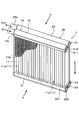
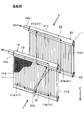
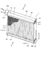
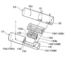
- the refrigerant evaporator 1 includes two evaporators 10 and 20 arranged in series with respect to the flow direction (flow direction of the fluid to be cooled) X of the blown air. It is prepared for.
- the evaporation unit disposed on the leeward side (downstream side) in the flow direction of the blown air is referred to as a leeward evaporation unit (first evaporation unit) 10.
- the evaporator disposed on the windward side (upstream side) in the flow direction of the blown air is referred to as the windward evaporator 20 (second evaporator).
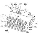
- the basic configurations of the leeward side evaporation unit 10 and the leeward side evaporation unit 20 are the same, and the core units 11 and 21 and a pair of tank units 12, 13, 22, which are arranged on both upper and lower sides of the core units 11 and 21, 23.
- the core part in the leeward evaporator 10 is referred to as the leeward core part 11
- the core part in the leeward evaporator 20 is referred to as the windward core part 21.
- the tank portion disposed on the upper side is referred to as a first leeward tank portion 12 (third tank portion) and is disposed on the lower side.
- This part is referred to as a second leeward tank part 13 (first tank part).
- the tank part disposed on the upper side is referred to as a first windward tank part 22 (fourth tank part) and is disposed on the lower side.
- the tank part is referred to as a second upwind tank part 23 (second tank part).
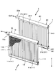
- Each of the leeward core portion 11 and the leeward core portion 21 of the present embodiment includes a plurality of tubes 111 and 211 extending in the vertical direction (vertical direction) and fins 112 joined between the adjacent tubes 111 and 211. It is comprised by the laminated body arrange
- the stacking direction in the stacked body of the plurality of tubes 111 and 211 and the plurality of fins 112 is referred to as a tube stacking direction. 1 and 2, only a part of the fins 112 is illustrated for clarity of illustration, but the fins 112 are arranged over substantially the entire area between the adjacent tubes 111.
- the fins of the windward evaporator 20 are not shown for clarity of illustration, but the windward evaporator 20 is also adjacent to the windward evaporator 10 as in the case of the leeward evaporator 10. Fins are arranged over substantially the entire area between the combined tubes 211.
- the leeward side core portion 11 includes a first leeward side core portion 11a constituted by a part of the plurality of tubes 111 and a second leeward side core portion 11b constituted by the remaining tube groups.
- the 1st leeward side core part 11a in this embodiment may be used as an example of the 1st core part which has a group of the some tube 111.
- FIG. The second leeward core portion 11b may be used as an example of a second core portion having the remaining group of the plurality of tubes 111.
- the first leeward is a tube group existing on the left side in the tube stacking direction.
- the side core part 11a is comprised, and the 2nd leeward side core part 11b is comprised by the tube group which exists in the right side of a tube lamination direction.
- the windward core portion 21 includes a first windward core portion 21a constituted by a part of the tube 211 and a second windward core portion 21b constituted by the remaining tube group among the plurality of tubes 211.
- the 1st windward core part 21a in this embodiment is used as an example of the 3rd core part which has a group of the some tube 211 which opposes at least one part of a 1st core part in the flow direction of to-be-cooled fluid. May be.
- the 2nd windward core part 21b may be used as an example of the 4th core part which has a group of the some tube 211 which opposes at least one part of a 2nd core part in the flow direction of to-be-cooled fluid.
- the first windward core portion 21a when the windward core portion 21 is viewed from the downstream side of the blown air flow, the first windward core portion 21a is configured by the tube group existing on the left side in the tube stacking direction and exists on the right side in the tube stacking direction.
- the tube group constitutes the second upwind core portion 21b.
- the first leeward side core portion 11a and the first leeward side core portion 21a are arranged so as to overlap (oppose) when viewed from the flow direction of the blown air, and the second leeward side.
- the side core portion 11b and the second upwind core portion 21b are arranged so as to overlap (oppose) each other.
- Each of the tubes 111 and 211 is formed of a flat tube in which a refrigerant passage through which a refrigerant flows is formed and a cross-sectional shape thereof is a flat shape extending along the flow direction of the blown air.
- the tube 111 of the leeward core portion 11 has one end side (upper end side) in the longitudinal direction connected to the first leeward side tank portion 12 and the other end side (lower end side) in the longitudinal direction is connected to the second leeward side tank portion. 13 is connected.
- the tube 211 of the windward core portion 21 has one end side (upper end side) in the longitudinal direction connected to the first windward tank portion 22 and the other end side (lower end side) in the longitudinal direction is connected to the second windward side. It is connected to the tank part 23.
- Each fin 112 is a corrugated fin formed by bending a thin plate material into a wave shape, and is joined to the flat outer surface side of the tubes 111 and 211, and heat exchange promoting means for expanding the heat transfer area between the blown air and the refrigerant.
- side plates 113 and 213 that reinforce the core portions 11 and 12 are arranged at both ends in the tube laminating direction.
- the side plates 113 and 213 are joined to the fins 112 arranged on the outermost side in the tube stacking direction.
- the first leeward tank section 12 is closed at one end (right end when viewed from the blown air flow downstream side) and at the other end (left end when viewed from the blown air flow downstream). It is comprised with the cylindrical member to which the refrigerant
- the first leeward tank section 12 has a through hole (not shown) in which one end side (upper end side) of each tube 111 is inserted and joined at the bottom.
- the first leeward tank unit 12 is configured so that the internal space thereof communicates with each tube 111 of the leeward core unit 11, and distributes the refrigerant to the core units 11 a and 11 b of the leeward core unit 11. Functions as a refrigerant distributor.
- the refrigerant introduction part 12a may be located closer to the first core part than the second core part.
- the first windward tank portion 22 is closed at one end side, and at the other end side, a refrigerant outlet portion 22a for leading the refrigerant from the inside of the tank to the suction side of the compressor (not shown) is formed inside the tank. It is comprised with the cylindrical member.
- the first upwind tank section 22 has a through hole (not shown) in which one end side (upper end side) of each tube 211 is inserted and joined at the bottom. That is, the first upwind tank section 22 is configured such that the internal space thereof communicates with each tube 211 of the upwind core section 21, and the refrigerant from each of the core sections 21 a and 21 b of the upwind core section 21 is supplied. It functions as a refrigerant collecting part that collects.
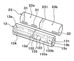
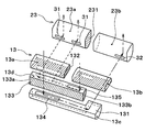
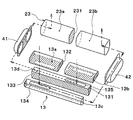
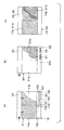
- the second leeward tank unit 13 is composed of a cylindrical member whose both ends are closed.
- the second leeward tank portion 13 has a through hole (not shown) in which the other end side (lower end side) of each tube 111 is inserted and joined to the ceiling portion. That is, the second leeward tank unit 13 is configured such that its internal space communicates with each tube 111.
- a first partition 131 is disposed at the center in the up-down direction inside the second leeward tank unit 13, and the tank interior space is formed by the first partition 131. Is partitioned into an upper space and a lower space.
- the second partition 132 is disposed in the center of the longitudinal direction (tube stacking direction) inside the upper space, and the upper space causes the first leeward core portion 11a to pass through the second partition 132. It is partitioned into a space in which each tube 111 constituting the communication communicates with a space in which each tube 111 constituting the second leeward core portion 11b communicates.
- the space communicating with each tube 111 constituting the first leeward core 11 a collects the refrigerant from the first leeward core 11 a.
- the space that constitutes the first refrigerant gathering portion 13a and communicates with each tube 111 constituting the second leeward core portion 11b constitutes the second refrigerant gathering portion 13b that gathers the refrigerant from the second leeward core portion 11b.
- a third partition portion 133 that divides a part of the lower space into two in the flow direction (front-rear direction) of the blown air is disposed.
- the third partition 133 has two members, a first member 133a and a second member 133b.
- the first member 133a is connected to an end of the second leeward tank portion 13 on the side close to the refrigerant introduction portion 12a (left side in the drawing) on one end side in the longitudinal direction, The part is formed to be divided into two in the flow direction of the blown air.
- the 1st member 133a is arrange
- the second member 133b is connected to an end portion on the other end side in the longitudinal direction of the first member 133a and extends toward the second windward tank portion 23 side (upstream side of the blown air flow).
- the third partition 133 configured in this manner.
- the first partition 131 communicates the first communication hole 134 for communicating the first refrigerant assembly 13a and the first lower space 13c, and the second communication for communicating the second refrigerant assembly 13b and the second lower space 13d.
- Two communication holes 135 are formed. More specifically, the first communication hole 134 is disposed on the downstream side of the blown air flow in the first partition portion 131 and on the side close to the refrigerant introduction portion 12a in the tube stacking direction. Moreover, the 2nd communicating hole 135 is arrange
- the second upwind tank unit 23 is formed of a cylindrical member whose both ends are closed.
- the second upwind tank portion 23 has a through hole (not shown) in which the other end side (lower end side) of each tube 211 is inserted and joined to the ceiling portion. That is, the second upwind tank unit 23 is configured such that its internal space communicates with each tube 211.
- a partition 231 is arranged at a central position in the longitudinal direction, and by this partition 231, each tube 211 whose tank internal space constitutes the first upwind core section 21a. Are communicated with each other and a space with which each of the tubes 211 constituting the second upwind core portion 21b communicates.
- a space communicating with each tube 211 constituting the first windward core portion 21a distributes the refrigerant to the first windward core portion 21a.
- the space which comprises the part 23a and each tube 211 which comprises the 2nd windward core part 21b communicates comprises the 2nd refrigerant
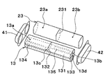
- the second lower space 13 d of the second leeward tank unit 13 and the first refrigerant distribution unit 23 a of the second leeward tank unit 23 are connected via the first communication unit 31.
- the first lower space 13 c of the second leeward tank unit 13 and the second refrigerant distribution unit 23 b of the second leeward tank unit 23 are connected via a second communication unit 32.
- the 1st communication part 31 is extended in the tube lamination direction, and is in the area
- the 2nd communication part 32 is extended in the tube lamination direction, and is 1 in the edge part vicinity of the side far from the refrigerant
- the refrigerant flow in the second leeward tank unit 13 and the second leeward tank unit 23 will be described.
- the refrigerant that has flowed out from each tube 111 constituting the first leeward core portion 11a gathers in the first refrigerant collecting portion 13a of the second leeward tank portion 13, and then It flows into the first lower space 13 c through the one communication hole 134.
- the refrigerant that has flowed into the first lower space 13c flows through the first lower space 13c from the side closer to the refrigerant introduction part 12a in the tube stacking direction toward the side farther away, and the second refrigerant via the second communication part 32. It flows into the second refrigerant distribution portion 23b of the windward side tank portion 23.
- the refrigerant that has flowed into the second refrigerant distribution portion 23b is distributed to the tubes 211 that constitute the second upwind core portion 21b.
- the refrigerant 13b may be used as an example of a refrigerant flow changing unit that guides the refrigerant 13b to the first refrigerant distribution unit 23a.
- the refrigerant flows from the side closer to the refrigerant introduction portion 12a in the tube stacking direction toward the far side, and the second leeward tank portion 13 2 In the lower space 13d, the refrigerant flows from the far side to the near side to the refrigerant introduction portion 12a in the tube stacking direction. That is, the refrigerant flow in the first lower space 13c and the refrigerant flow in the second lower space 13d are counterflows.
- the refrigerant flows from the first refrigerant assembly portion 13a to the second refrigerant distribution portion 23b, and the second refrigerant assembly
- the refrigerant flow from the part 13b to the first refrigerant distribution part 23a is in a non-intersecting state when viewed from the longitudinal direction of the tube.
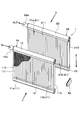
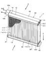
- first leeward tank unit 12 and the first leeward tank unit 22 are integrally formed, and the second leeward tank unit 13 and the first leeward tank unit 23 are integrally formed.
- first header tank 51 the unit in which the first leeward tank unit 12 and the first leeward tank unit 22 are integrated
- second leeward tank unit 13 and the second leeward tank unit 23 are integrated. This is referred to as a second header tank 52.
- Each header tank 51, 52 has header plates 511, 521 and tank forming members 512, 522 to which both tubes 111, 211 arranged in two rows in the flow direction of the blown air are fixed.
- the tank forming members 512 and 522 are fixed to the header plates 511 and 521 so as to form a space in which refrigerant flows.
- the tank forming members 512 and 522 are formed in a double mountain shape (W shape) when viewed from the longitudinal direction by pressing a flat metal.
- the 1st leeward side tank part 12 and the 1st leeward side tank part 22 are divided by joining the double mountain-shaped center part of the tank formation member 512 to the header plate 511. Further, the two mountain-shaped central portions of the tank forming member 522 are joined to the header plate 521 so that the second leeward tank portion 13 and the second leeward tank portion 23 are partitioned.
- the first communication portion 31 and the second communication portion 32 are configured by forming a partial gap between the central portion of the two ridges of the tank forming member 522 and the header plate 521.
- the lower spaces 13c and 13d of the second leeward tank portion 13 guide the refrigerant in the first refrigerant assembly portion 13a to the second refrigerant distribution portion 23b and also supply the refrigerant in the second refrigerant assembly portion 13b. Since it is configured to lead to the first refrigerant distributor 23a, the refrigerant flow direction can be changed in the width direction (tube stacking direction) of the cores 11 and 21 in the second leeward tank unit 13. At this time, it is not necessary to provide another member other than the second leeward tank unit 13 in order to change the flow direction of the refrigerant. Therefore, it is possible to change the flow direction of the refrigerant in the width direction of the core portions 11 and 21 while suppressing an increase in the refrigerant filling amount.
- the refrigerant flow changing section that is, the lower spaces 13c and 13d of the second leeward tank section 13, the refrigerant flow from the first refrigerant assembly section 13a to the second refrigerant distribution section 23b, and the second The refrigerant flow from the two refrigerant assembly parts 13b to the first refrigerant distribution part 23a is configured to be in a non-intersecting state when viewed from the tube longitudinal direction.
- the refrigerant evaporator according to the comparative example is shown in FIG.
- the refrigerant evaporator 1 according to the comparative example crosses the refrigerant after passing through the leeward core portion 11 on the left and right (in the width direction of the core portion or in the tube stacking direction) before flowing into the leeward core portion.
- the cross communication part 30 ⁇ / b> J is provided at the central part in the left-right direction of the second leeward tank part 13.
- the dashed-dotted line arrow and broken-line arrow in FIG. 5 have shown the flow of the refrigerant
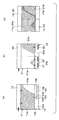
- FIG. 6 And distribution of the liquid-phase refrigerant
- the distribution of the phase refrigerant is shown in FIG. 6 (a) and 7 (a) show the distribution of the liquid-phase refrigerant flowing through the leeward core portion 11, and FIGS. 6 (b) and 7 (b) show the liquid phase flowing through the leeward core portion 21.
- FIG. 7C show the synthesis of the distribution of the liquid-phase refrigerant flowing through the core portions 11 and 21.
- 6 and 7 show the distribution of the liquid-phase refrigerant when the refrigerant evaporator 1 is viewed from the direction of the arrow Y in FIG. 1 (the direction opposite to the flow direction X of the blown air).
- a portion indicated by a portion indicates a portion where the liquid-phase refrigerant exists.
- the refrigerant evaporator 1 according to the comparative example and the refrigerant evaporator according to the present embodiment. 1 is the same, and a portion where the liquid refrigerant is difficult to flow (a white portion on the lower right side in the drawing) is generated on the second leeward core portion 11b far from the refrigerant introduction portion 12a.
- the sensible heat of the refrigerant is merely absorbed from the blown air at a place where the liquid phase refrigerant is difficult to flow, so that the blown air is sufficiently cooled. Can not do it. As a result, a temperature distribution is generated in the blown air passing through the refrigerant evaporator 1.
- the second communication portion 32 is used as the refrigerant in the tube stacking direction of the second windward tank portion 23. Since it is connected to the end portion on the side far from the introduction portion 12a, as shown in FIG. 7B, in the windward core portion 21, there is a liquid near the end portion on the side far from the refrigerant introduction portion 12a in the tube stacking direction.
- the phase refrigerant is easy to flow.
- the portion where the liquid phase refrigerant easily flows in the leeward core portion 21 is polymerized when facing the portion where the liquid phase refrigerant hardly flows in the leeward core portion 11, that is, when viewed from the flow direction X of the blown air.
- positioning in this way, it can suppress that temperature distribution arises in the ventilation air which passes through the refrigerant
- the third partition part 133 of the present embodiment is connected to the inner wall surface of the second leeward tank part 13 at both ends in the longitudinal direction (tube stacking direction). With the third partition portion 133 configured in this manner, the entire area of the lower space of the second leeward tank portion 13 is divided into two of the first lower space 13c and the second lower space 13d in the flow direction of the blown air. It is divided into two.
- the first lower space 13c is arranged on the downstream side of the blown air flow with respect to the second lower space 13d.
- the 3rd partition part 133 is arrange
- the second leeward tank unit 13 and the second leeward tank unit 23 are connected by a joint 42.
- the joint 42 is connected to each end of the second leeward tank unit 13 and the second leeward tank unit 23 on the side farther from the refrigerant introduction unit 12a in the tube stacking direction.
- a refrigerant flow path through which the refrigerant flows is formed.
- the first lower space 13 c of the second leeward tank unit 13 and the second refrigerant distribution unit 23 b of the second leeward tank unit 23 are connected via a refrigerant flow path inside the joint 42.
- the joint 42 in this embodiment may be used as an example of a 2nd communication part.
- FIG. 11 As indicated by the one-dot chain line arrow in FIG. 11, the refrigerant flowing out from each tube 111 constituting the first leeward side core portion 11a collects in the first refrigerant collecting portion 13a of the second leeward side tank portion 13, It flows into the first lower space 13 c through the one communication hole 134.
- the refrigerant that has flowed into the first lower space 13c flows through the first lower space 13c from the side closer to the refrigerant introduction portion 12a in the tube stacking direction toward the far side, and through the refrigerant flow path in the joint 42. It flows into the second refrigerant distributor 23b of the second upwind tank 23.
- the refrigerant that has flowed into the second refrigerant distribution portion 23b is distributed to the tubes 211 that constitute the second upwind core portion 21b.
- the third embodiment is a communication portion between the second lower space 13d of the second leeward tank unit 13 and the first refrigerant distribution unit 23a of the second leeward tank unit 23. Are different in configuration.
- the second leeward tank unit 13 and the second leeward tank unit 23 of the present embodiment are connected by a first joint 41 and a second joint 42.
- the first joint 41 is connected to the end portions of the second leeward tank portion 13 and the second leeward tank portion 23 on the side close to the refrigerant introduction portion 12a in the tube stacking direction.
- the second joint 42 is connected to the ends of the second leeward tank unit 13 and the second leeward tank unit 23 on the side farther from the refrigerant introduction part 12a in the tube stacking direction.
- a refrigerant flow path through which a refrigerant flows is formed.
- the second lower space 13 d of the second leeward tank unit 13 and the first refrigerant distribution unit 23 a of the second leeward tank unit 23 are connected via a refrigerant flow path inside the first joint 41.
- the first lower space 13c of the second leeward tank unit 13 and the second refrigerant distribution unit 23b of the second leeward tank unit 23 are connected via a refrigerant flow path inside the second joint 42.
- the 1st joint 41 in this embodiment may be used as an example of the 1st communication part
- the 2nd joint 42 in this embodiment may be used as an example of the 2nd communication part.
- the refrigerant that has flowed out from the tubes 111 constituting the second leeward core portion 11 b is collected in the second refrigerant collecting portion 13 b of the second leeward tank portion 13, and then the second It flows into the second lower space 13d through the communication hole 135.
- the refrigerant flowing into the second lower space 13d flows in the second lower space 13d from the side far from the refrigerant introduction part 12a in the tube stacking direction toward the side closer to the refrigerant flow path in the first joint 41. And flows into the first refrigerant distributor 23a of the second upwind tank 23.
- the refrigerant that has flowed into the first refrigerant distribution portion 23a is distributed to the tubes 211 that constitute the first upwind core portion 21a.
- FIGS. 16 to 18 a fourth embodiment of the present disclosure will be described based on FIGS. 16 to 18.
- the fourth embodiment differs from the first embodiment in the configuration of the second leeward tank unit 13 and the second leeward tank unit 23.
- the second leeward tank unit 13 has a tank inner space at a substantially central position in the tube stacking direction, and a first space 130A and a second space 130B in the tube stacking direction.
- the 2nd partition part 132 divided into two is arrange
- the first space 130A is disposed at a portion (left side of the drawing) corresponding to the first leeward core portion 11a
- the second space 130B is disposed at a portion (right side of the drawing) corresponding to the second leeward core portion 11b. Yes.
- a first partition 131 is disposed at a substantially central position in the vertical direction, and the first partition 131 partitions the second space 130B into an upper space and a lower space. .
- the first space 130A constitutes a space in which the tubes 111 constituting the first leeward core part 11a communicate with each other.
- the upper space of the two spaces 130B constitutes a space in which the tubes 111 constituting the second leeward core portion 11b communicate.
- the space (that is, the first space 130A) communicating with each tube 111 constituting the first leeward core unit 11a is the first leeward core unit.
- a space (that is, an upper space of the second space 130B) that constitutes the first refrigerant collecting portion 13a that collects the refrigerant from 11a and communicates with each tube 111 constituting the second leeward core portion 11b is the second leeward
- coolant from the side core part 11b is comprised.
- the third partition portion 133 partitions a part of the lower space into two in the flow direction (front-rear direction) of the blown air. Is arranged.
- the third partition 133 has two members, a first member 133a and a second member 133b.
- the first member 133a is on one end side in the longitudinal direction, is connected to the second partition 132, and is formed so as to partition a part of the lower space into two in the flow direction of the blown air.
- the 1st member 133a is arrange
- the second member 133b is connected to an end portion on the other end side in the longitudinal direction of the first member 133a and extends toward the second windward tank portion 23 side (upstream side of the blown air flow).
- the lower space of the second space 130B of the second leeward tank portion 13 is formed in a substantially L shape when viewed from the tube longitudinal direction Z. It is partitioned into a first lower space 13c and a second lower space 13d extending in the tube stacking direction.
- the second partition part 132 is formed with a first communication hole 134 that allows the first refrigerant assembly part 13a and the first lower space 13c to communicate with each other.
- the first partition 131 is formed with a second communication hole 135 that allows the second refrigerant assembly portion 13b and the second lower space 13d to communicate with each other.
- the 1st communicating hole 134 is arrange
- the 2nd communicating hole 135 is arrange
- the partition part 231 is not arranged inside the second upwind tank part 23.
- the inside of the 2nd windward side tank part 23 comprises the refrigerant
- the second upwind tank unit 23 includes a first communication unit 31 that allows the refrigerant to flow into the second upwind tank unit 23 from the second refrigerant collection unit 13b, and a second upwind tank unit from the first refrigerant collection unit 13a.
- the second communication portion 32 that allows the refrigerant to flow into the inside 23 is connected.
- the first communication part 31 and the second communication part 32 are respectively disposed at portions (right side of the drawing) corresponding to the tubes 211 belonging to the second windward core part 21b in the second windward tank part 23.
- the 1st communication part 31 is arrange
- the refrigerant flow in the second leeward tank unit 13 and the second leeward tank unit 23 will be described.
- the refrigerant flowing out from each tube 111 constituting the first leeward side core portion 11a is collected in the first refrigerant collecting portion 13a of the second leeward side tank portion 13, It flows into the first lower space 13 c through the one communication hole 134.
- the refrigerant that has flowed into the first lower space 13c flows through the first lower space 13c from the side closer to the refrigerant introduction part 12a in the tube stacking direction toward the side farther away, and the second refrigerant via the second communication part 32. It flows into the windward side tank part 23 in the side far from the refrigerant introduction part 12a, and is distributed to each tube 211 of the windward side evaporation part 20.
- lower space 13c, 13d of the 2nd leeward tank part 13 in this embodiment may be used as an example of a refrigerant flow change part.
- the refrigerant distribution section 23c (second windward tank section) from the first refrigerant assembly section 13a via the second communication section 32. 23) and the refrigerant flow from the second refrigerant assembly part 13b to the refrigerant distribution part 23c via the first communication part 31 are in a non-crossing state when viewed from the longitudinal direction of the tube.
- the lower spaces 13c and 13d of the second leeward tank portion 13 guide the refrigerant from the first refrigerant assembly portion 13a to the refrigerant distribution portion 23c via the second communication portion 32, and the second space 13c and 13d. Since the refrigerant from the refrigerant collecting portion 13b is configured to be guided to the refrigerant distributing portion 23c via the first communication portion 31, the flow direction of the refrigerant in the second leeward tank portion 13 is changed between the core portions 11 and 21. It can be replaced in the width direction (tube stacking direction).
- the refrigerant flow changing unit that is, the lower spaces 13c and 13d of the second leeward tank unit 13 is configured so that the refrigerant is supplied from the first refrigerant assembly unit 13a to the refrigerant distribution unit 23c via the second communication unit 32.
- the refrigerant flow from the second refrigerant collecting portion 13b to the refrigerant distribution portion 23c via the first communication portion 31 are in a non-intersecting state when viewed from the longitudinal direction of the tube. Is done. Thereby, it becomes possible to improve the cooling performance of the blast air in the refrigerant evaporator 1 similarly to the said 1st Embodiment.
- FIG. 18 is a drawing corresponding to FIG. 7 of the first embodiment.
- the liquid-phase refrigerant flowing through the leeward core portion 11 As shown in FIG. 18A, the liquid-phase refrigerant hardly flows to the side farther from the refrigerant introduction portion 12a in the second leeward core portion 11b. A spot (a white spot on the lower right side in the figure) occurs.
- both the first communication portion 31 and the second communication portion 32 are located farther from the refrigerant introduction portion 12a in the tube stacking direction of the second windward side tank portion 23. Since they are connected, as shown in FIG. 18B, in the windward core portion 21, the liquid-phase refrigerant easily flows to the side far from the refrigerant introduction portion 12 a in the tube stacking direction.
- first leeward tank unit 12 and the first leeward tank unit 22 are integrally formed, and the second leeward tank unit 13 and the first leeward tank unit 23 are integrally formed.
- present invention is not limited to this, and the first leeward tank unit 12 and the first leeward tank unit 22 are configured separately, and the second leeward tank unit 13 and the first leeward tank unit 23 are configured separately. May be configured separately.
Landscapes
- Engineering & Computer Science (AREA)
- Physics & Mathematics (AREA)
- Mechanical Engineering (AREA)
- Thermal Sciences (AREA)
- General Engineering & Computer Science (AREA)
- Heat-Exchange Devices With Radiators And Conduit Assemblies (AREA)
Abstract
Refrigerant flow changing parts (13c, 13d), which guide the refrigerant in a first refrigerant convergence part (13a) to a second refrigerant distribution part (23b) and guide the refrigerant in a second refrigerant convergence part (13b) to a first refrigerant distribution part (23a), are provided inside a second downstream tank part (13) of a downstream evaporation part (10). The refrigerant flow changing parts (13c, 13d) are constructed such that the flow of the refrigerant guided from the first refrigerant convergence part (13a) to the second refrigerant distribution part (23b) and the flow of the refrigerant guided from the second refrigerant convergence part (13b) to the first refrigerant distribution part (23a) are in a nonintersecting state when viewed from the lengthwise direction of tubes (111, 222). Thus, the refrigerant flow can be switched in the width direction of core parts without increasing the filling amount of the refrigerant, and the cooling performance with respect to a fluid to be cooled can be improved.
Description
本出願は、当該開示内容が参照によって本出願に組み込まれた、2012年10月31日に出願された日本特許出願2012-240025を基にしている。
This application is based on Japanese Patent Application No. 2012-240025 filed on October 31, 2012, the disclosure of which is incorporated herein by reference.
本開示は、被冷却流体から吸熱して冷媒を蒸発させることで、被冷却流体を冷却する冷媒蒸発器に関する。
The present disclosure relates to a refrigerant evaporator that cools a fluid to be cooled by absorbing heat from the fluid to be cooled and evaporating the refrigerant.
この種の冷媒蒸発器としては、複数のチューブを積層して構成されるコア部、および複数のチューブの両端部に接続された一対のタンク部を備える第1、第2蒸発部を被冷却流体の流れ方向に直列に配置し、各蒸発部における一方のタンク部同士を一対の連通部を介して連結する構成が知られている(例えば、特許文献1参照)。
As this type of refrigerant evaporator, the first and second evaporators including a core part configured by stacking a plurality of tubes and a pair of tank parts connected to both ends of the plurality of tubes are used as fluids to be cooled. There is known a configuration in which the tanks are arranged in series in the flow direction and one tank unit in each evaporation unit is connected to each other via a pair of communication units (for example, see Patent Document 1).
この特許文献1の冷媒蒸発器では、第1蒸発部のコア部を流れた冷媒を、各蒸発部の一方のタンク部および当該タンク部同士を連結する一対の連通部を介して第2蒸発部のコア部に流す際に、冷媒の流れをコア部の幅方向(チューブ積層方向、左右方向)で入れ替える構成としている。つまり、冷媒蒸発器は、一対の連通部のうち、一方の連通部によって、第1蒸発部のコア部の幅方向一側を流れる冷媒を第2蒸発部のコア部の幅方向他側に流すと共に、他方の連通部によって第1蒸発部のコア部の幅方向他側を流れる冷媒を第2蒸発部のコア部の幅方向一側に流すように構成されている。
In the refrigerant evaporator disclosed in Patent Document 1, the refrigerant that has flowed through the core portion of the first evaporation section is supplied to the second evaporation section via one tank section of each evaporation section and a pair of communication sections that connect the tank sections to each other. When flowing through the core portion, the refrigerant flow is switched in the width direction of the core portion (tube stacking direction, left-right direction). That is, in the refrigerant evaporator, the refrigerant flowing on one side in the width direction of the core portion of the first evaporation portion is caused to flow to the other side in the width direction of the core portion of the second evaporation portion by one of the communication portions. In addition, the refrigerant that flows on the other side in the width direction of the core portion of the first evaporation portion is caused to flow to one side in the width direction of the core portion of the second evaporation portion by the other communication portion.
また、特許文献1の冷媒蒸発器では、一対の連通部は、冷媒流れが左右交差する交差連通部である。そして、この交差連通部は、第1蒸発部または第2蒸発部のタンク部、もしくは、第1蒸発部のタンク部と第2蒸発部のタンク部との間に設けられた中間タンクに配置されている。
Further, in the refrigerant evaporator of Patent Document 1, the pair of communication portions are cross communication portions where the refrigerant flows cross right and left. And this intersection communication part is arrange | positioned in the intermediate | middle tank provided between the tank part of the 1st evaporation part or the 2nd evaporation part, or the tank part of the 1st evaporation part, and the tank part of the 2nd evaporation part. ing.
しかしながら、本願の発明者の検討によると、上記特許文献1に記載の冷媒蒸発器のように、交差連通部を中間タンクに設ける構成とすると、中間タンクを設けたことにより冷媒蒸発器の内容積が増加するので、冷媒封入量の増加を招くことがある。
However, according to the study of the inventors of the present application, when the cross communication portion is provided in the intermediate tank as in the refrigerant evaporator described in Patent Document 1, the internal volume of the refrigerant evaporator is provided by providing the intermediate tank. May increase the amount of refrigerant enclosed.
また、交差連通部を第1蒸発部または第2蒸発部のタンク部に設ける構成とすると、当該交差連通部を隣り合うチューブ間に配置する必要があるので、交差連通部の冷媒通路断面積が小さくなってしまう。このため、交差連通部を通過する際に生じる冷媒の圧力損失が大きくなり、冷媒蒸発器における被冷却流体の冷却性能が低下するおそれがある。
Further, when the cross communication portion is provided in the tank portion of the first evaporation portion or the second evaporation portion, the cross communication portion needs to be disposed between adjacent tubes, so that the refrigerant passage cross-sectional area of the cross communication portion is increased. It gets smaller. For this reason, the pressure loss of the refrigerant | coolant which arises when passing a cross communication part becomes large, and there exists a possibility that the cooling performance of the to-be-cooled fluid in a refrigerant | coolant evaporator may fall.
本開示は上記点に鑑みて、冷媒封入量の増加を抑制しつつ冷媒流れをコア部の幅方向で入れ替えることができ、さらに被冷却流体の冷却性能を向上させることができる冷媒蒸発器を提供することを目的とする。
In view of the above points, the present disclosure provides a refrigerant evaporator capable of switching the refrigerant flow in the width direction of the core portion while suppressing an increase in the amount of refrigerant enclosed, and further improving the cooling performance of the fluid to be cooled. The purpose is to do.
本開示の第1態様によると、外部を流れる被冷却流体と冷媒との間で熱交換を行う冷媒蒸発器は、被冷却流体の流れ方向に対して直列に配置された第1蒸発部、および第2蒸発部を備える。第1蒸発部は、冷媒が流れる複数の積層されたチューブを有するコア部と、複数のチューブの両端部に接続され、複数のチューブを流れる冷媒の集合あるいは分配を行う一対のタンク部とを有する。第2蒸発部は、冷媒が流れる複数の積層されたチューブを有するコア部と、複数のチューブの両端部に接続され、複数のチューブを流れる冷媒の集合あるいは分配を行う一対のタンク部とを有する。第1蒸発部のコア部は、複数のチューブの一群を有する第1コア部、および複数のチューブの残りの一群を有する第2コア部を有している。第2蒸発部のコア部は、被冷却流体の流れ方向において第1コア部の少なくとも一部と対向する複数のチューブの一群を有する第3コア部、および被冷却流体の流れ方向において第2コア部の少なくとも一部と対向する複数のチューブの一群を有する第4コア部を有する。第1蒸発部の一対のタンク部の一方である第1タンク部は、第1コア部からの冷媒を集合させる第1冷媒集合部、および第2コア部からの冷媒を集合させる第2冷媒集合部を含んでいる。第2蒸発部の一対のタンク部の一方である第2タンク部は、第3コア部に冷媒を分配させる第1冷媒分配部、および第4コア部に冷媒を分配させる第2冷媒分配部を含んでいる。第2冷媒集合部と第1冷媒分配部とは、第1連通部を介して接続されており、第1冷媒集合部と第2冷媒分配部とは、第2連通部を介して接続されている。第1蒸発部の第1タンク部および第2蒸発部の第2タンク部のうち、少なくとも一方は、第1冷媒集合部の冷媒を第2冷媒分配部に導くとともに、第2冷媒集合部の冷媒を第1冷媒分配部に導く冷媒流変更部を内部に有している。冷媒流変更部は、第1冷媒集合部から冷媒を第2冷媒分配部への冷媒流れ、および、第2冷媒集合部から冷媒を第1冷媒分配部への冷媒流れが、チューブの長手方向から見たときに非交差状態となるように構成されている。
According to the first aspect of the present disclosure, the refrigerant evaporator that performs heat exchange between the fluid to be cooled flowing outside and the refrigerant includes the first evaporator disposed in series with respect to the flow direction of the fluid to be cooled, and A second evaporator is provided. The first evaporation section includes a core section having a plurality of stacked tubes through which the refrigerant flows, and a pair of tank sections that are connected to both ends of the plurality of tubes and collect or distribute the refrigerant flowing through the plurality of tubes. . The second evaporating unit includes a core unit having a plurality of stacked tubes through which the refrigerant flows, and a pair of tank units that are connected to both ends of the plurality of tubes and collect or distribute the refrigerant flowing through the plurality of tubes. . The core part of the first evaporation part has a first core part having a group of a plurality of tubes and a second core part having a remaining group of the plurality of tubes. The core part of the second evaporation part has a third core part having a group of a plurality of tubes facing at least a part of the first core part in the flow direction of the fluid to be cooled, and the second core in the flow direction of the fluid to be cooled. A fourth core portion having a group of a plurality of tubes facing at least a part of the portion. The first tank part, which is one of the pair of tank parts of the first evaporation part, includes a first refrigerant assembly part that collects refrigerant from the first core part, and a second refrigerant assembly that collects refrigerant from the second core part. Contains parts. The second tank part, which is one of the pair of tank parts of the second evaporation part, includes a first refrigerant distribution part that distributes the refrigerant to the third core part, and a second refrigerant distribution part that distributes the refrigerant to the fourth core part. Contains. The second refrigerant collecting part and the first refrigerant distributing part are connected via a first communicating part, and the first refrigerant collecting part and the second refrigerant distributing part are connected via a second communicating part. Yes. At least one of the first tank unit of the first evaporation unit and the second tank unit of the second evaporation unit guides the refrigerant of the first refrigerant assembly unit to the second refrigerant distribution unit, and the refrigerant of the second refrigerant assembly unit Has a refrigerant flow changing section for guiding the refrigerant to the first refrigerant distribution section. The refrigerant flow changing unit is configured such that the refrigerant flow from the first refrigerant collecting unit to the second refrigerant distributing unit and the refrigerant flow from the second refrigerant collecting unit to the first refrigerant distributing unit are from the longitudinal direction of the tube. It is configured to be in a non-intersecting state when viewed.
これによれば、第1蒸発部の第1タンク部および第2蒸発部の第2タンク部のうち、少なくとも一方の内部に、第1冷媒集合部の冷媒を第2冷媒分配部に導くとともに、第2冷媒集合部の冷媒を第1冷媒分配部に導く冷媒流変更部を設けることで、当該少なくとも一方のタンク部内において、冷媒の流れ方向をコア部の幅方向で入れ替えることができる。このとき、冷媒の流れ方向を入れ替えるために、タンク部以外の別の部材(例えば、交差連通部や中間タンク等)を設ける必要がない。したがって、冷媒封入量の増加を抑制しつつ、冷媒の流れ方向をコア部の幅方向で入れ替えることが可能となる。
According to this, while guiding the refrigerant of the first refrigerant assembly part to the second refrigerant distribution part in at least one of the first tank part of the first evaporation part and the second tank part of the second evaporation part, By providing the refrigerant flow changing unit that guides the refrigerant of the second refrigerant collecting unit to the first refrigerant distributing unit, the flow direction of the refrigerant can be switched in the width direction of the core unit in the at least one tank unit. At this time, it is not necessary to provide another member (for example, a cross communication part or an intermediate tank) other than the tank part in order to change the flow direction of the refrigerant. Therefore, it is possible to change the flow direction of the refrigerant in the width direction of the core portion while suppressing an increase in the amount of refrigerant enclosed.
また、冷媒流変更部を、第1冷媒集合部からの冷媒を第2冷媒分配部へ導く冷媒流れ、および、第2冷媒集合部からの冷媒を第1冷媒分配部へ導く冷媒流れが、チューブの長手方向から見たときに非交差状態となるように構成することで、交差連通部を隣り合うチューブ間に配置する必要がない。従って、冷媒の流れ方向をコア部の幅方向で入れ替える際に生じる冷媒の圧力損失が大きくなることを抑制できる。このため、冷媒蒸発器における被冷却流体の冷却性能を向上させることができる。
In addition, the refrigerant flow changing unit has a refrigerant flow that guides the refrigerant from the first refrigerant collecting unit to the second refrigerant distributing unit, and a refrigerant flow that guides the refrigerant from the second refrigerant collecting unit to the first refrigerant distributing unit. By configuring so as to be in a non-intersecting state when viewed from the longitudinal direction, it is not necessary to arrange the cross communication portion between adjacent tubes. Therefore, it is possible to suppress an increase in refrigerant pressure loss that occurs when the refrigerant flow direction is switched in the width direction of the core portion. For this reason, the cooling performance of the fluid to be cooled in the refrigerant evaporator can be improved.
ここで、第1蒸発部の第2コア部では、当該第2コア部を構成する複数のチューブのうち、チューブ積層方向における冷媒導入部から遠い端部側に位置するチューブへ冷媒が流れ難く、冷媒の分配性が悪化し易い傾向がある。
Here, in the second core part of the first evaporation part, among the plurality of tubes constituting the second core part, it is difficult for the refrigerant to flow to the tube located on the end side far from the refrigerant introduction part in the tube stacking direction. There is a tendency that the distribution of the refrigerant tends to deteriorate.
本開示の第2態様によると、第1冷媒集合部と第2冷媒分配部とを連通させる第2連通部は、第2蒸発部の第2タンク部の、チューブの積層方向における一端部に接続されてもよい。この場合、第2タンク部の一端部は、チューブの積層方向における第2タンク部の他端部よりも冷媒導入部から遠い。
According to the second aspect of the present disclosure, the second communication part that communicates the first refrigerant assembly part and the second refrigerant distribution part is connected to one end part in the tube stacking direction of the second tank part of the second evaporation part. May be. In this case, one end portion of the second tank portion is farther from the refrigerant introduction portion than the other end portion of the second tank portion in the tube stacking direction.
これによれば、第2蒸発部において、第2タンク部のチューブ積層方向における冷媒導入部から遠い側の端部から、コア部へ冷媒を流入させることができるので、第2蒸発部の第4コア部のチューブ積層方向における冷媒導入部から遠い端部側に位置するチューブへ冷媒が流れ易い構成となる。
According to this, in the second evaporation part, the refrigerant can flow into the core part from the end of the second tank part farther from the refrigerant introduction part in the tube stacking direction. It becomes the structure which a refrigerant | coolant tends to flow into the tube located in the edge part side far from the refrigerant introduction part in the tube lamination direction of a core part.
このため、冷媒蒸発器を被冷却流体の流れ方向から見たときに、第1蒸発部の第2コア部および第2蒸発部の第4コア部における重合する部位の全域に液相冷媒が流れる。このように液相冷媒が分布する冷媒蒸発器では、各コア部のいずれかによって、冷媒の蒸発潜熱分の熱量を被冷却流体から吸熱するので、被冷却流体を充分に冷却することが可能となる。この結果、冷媒蒸発器を通過する被冷却流体に温度分布が生じてしまうことを抑制できる。
For this reason, when the refrigerant evaporator is viewed from the flow direction of the fluid to be cooled, the liquid-phase refrigerant flows over the entire region of the second core portion of the first evaporator and the fourth core portion of the second evaporator. . In the refrigerant evaporator in which the liquid-phase refrigerant is distributed in this manner, the heat quantity of the latent heat of evaporation of the refrigerant is absorbed from the cooled fluid by any of the core portions, so that the cooled fluid can be sufficiently cooled. Become. As a result, it can suppress that temperature distribution arises in the to-be-cooled fluid which passes a refrigerant | coolant evaporator.
本開示の第3態様によると、外部を流れる被冷却流体と冷媒との間で熱交換を行う冷媒蒸発器は、被冷却流体の流れ方向に対して直列に配置された第1蒸発部、および第2蒸発部を備える。第1蒸発部は、冷媒が流れる複数の積層されたチューブを有するコア部と、複数のチューブの両端部に接続され、複数のチューブを流れる冷媒の集合あるいは分配を行う一対のタンク部とを有する。第2蒸発部は、冷媒が流れる複数の積層されたチューブを有するコア部と、複数のチューブの両端部に接続され、複数のチューブを流れる冷媒の集合あるいは分配を行う一対のタンク部とを有する。第1蒸発部のコア部は、複数のチューブの一群を有する第1コア部、および複数のチューブの残りの一群を有する第2コア部を有している。第2蒸発部のコア部は、被冷却流体の流れ方向において第1コア部の少なくとも一部と対向する複数のチューブの一群を有する第3コア部、および被冷却流体の流れ方向において第2コア部の少なくとも一部と対向する複数のチューブの一群を有する第4コア部を有する。第1蒸発部の一対のタンク部の一方である第1タンク部は、第1コア部からの冷媒を集合させる第1冷媒集合部、および第2コア部からの冷媒を集合させる第2冷媒集合部を含んでいる。第1蒸発部の一対のタンク部のうち他方である第3タンク部は、第3タンク部内部に冷媒を導入するための冷媒導入部を有しており、冷媒導入部は、第2コア部よりも第1コア部の近くに位置している。第2蒸発部の一対のタンク部のうち一方である第2タンク部は、第2冷媒集合部から当該第2タンク部内に冷媒を流入させる第1連通部と、第1冷媒集合部から当該第2タンク部内に冷媒を流入させる第2連通部とに接続されている。第1連通部および第2連通部は、それぞれ、第2蒸発部の第2タンク部における第4コア部と対応する部位に配置されている。第1連通部は、第2連通部よりも、第3コア部に近い側に配置されている。第1蒸発部の第1タンク部および第2蒸発部の第2タンク部のうち、少なくとも一方は、第1冷媒集合部の冷媒を第2連通部に導くとともに、第2冷媒集合部の冷媒を第1連通部に導く冷媒流変更部を内部に有している。冷媒流変更部は、第1冷媒集合部から冷媒を第2連通部への冷媒流れ、および、第2冷媒集合部から冷媒を第1連通部への冷媒流れが、チューブの長手方向から見たときに非交差状態となるように構成されている。
According to the third aspect of the present disclosure, the refrigerant evaporator that performs heat exchange between the fluid to be cooled flowing outside and the refrigerant includes the first evaporator disposed in series with respect to the flow direction of the fluid to be cooled, and A second evaporator is provided. The first evaporation section includes a core section having a plurality of stacked tubes through which the refrigerant flows, and a pair of tank sections that are connected to both ends of the plurality of tubes and collect or distribute the refrigerant flowing through the plurality of tubes. . The second evaporating unit includes a core unit having a plurality of stacked tubes through which the refrigerant flows, and a pair of tank units that are connected to both ends of the plurality of tubes and collect or distribute the refrigerant flowing through the plurality of tubes. . The core part of the first evaporation part has a first core part having a group of a plurality of tubes and a second core part having a remaining group of the plurality of tubes. The core part of the second evaporation part has a third core part having a group of a plurality of tubes facing at least a part of the first core part in the flow direction of the fluid to be cooled, and the second core in the flow direction of the fluid to be cooled. A fourth core portion having a group of a plurality of tubes facing at least a part of the portion. The first tank part, which is one of the pair of tank parts of the first evaporation part, includes a first refrigerant assembly part that collects refrigerant from the first core part, and a second refrigerant assembly that collects refrigerant from the second core part. Contains parts. The third tank part, which is the other of the pair of tank parts of the first evaporation part, has a refrigerant introduction part for introducing a refrigerant into the third tank part, and the refrigerant introduction part is a second core part. Rather than the first core part. The second tank part, which is one of the pair of tank parts of the second evaporation part, includes a first communication part for allowing the refrigerant to flow into the second tank part from the second refrigerant assembly part, and the first refrigerant part from the first refrigerant assembly part. The second tank is connected to a second communication part for allowing the refrigerant to flow into the tank part. The first communication part and the second communication part are respectively arranged at portions corresponding to the fourth core part in the second tank part of the second evaporation part. The first communication part is disposed closer to the third core part than the second communication part. At least one of the first tank part of the first evaporation part and the second tank part of the second evaporation part guides the refrigerant of the first refrigerant assembly part to the second communication part, and the refrigerant of the second refrigerant assembly part. A refrigerant flow changing portion that leads to the first communication portion is provided inside. The refrigerant flow changing unit is a configuration in which the refrigerant flow from the first refrigerant collecting unit to the second communication unit and the refrigerant flow from the second refrigerant collecting unit to the first communication unit are viewed from the longitudinal direction of the tube. Sometimes configured to be non-intersecting.
これによれば、第1蒸発部の第1タンク部および第2蒸発部の第2タンク部のうち、少なくとも一方の内部に、第1冷媒集合部の冷媒を第2連通部に導くとともに、第2冷媒集合部の冷媒を第1連通部に導く冷媒流変更部を設けることで、当該少なくとも一方のタンク部内において、冷媒の流れ方向をコア部の幅方向で入れ替えることができる。このとき、冷媒の流れ方向を入れ替えるために、タンク部以外の別の部材を設ける必要がない。したがって、冷媒封入量の増加を抑制しつつ、冷媒の流れ方向をコア部の幅方向で入れ替えることが可能となる。
According to this, the refrigerant of the first refrigerant assembly portion is guided to the second communication portion in at least one of the first tank portion of the first evaporation portion and the second tank portion of the second evaporation portion, and the first By providing the refrigerant flow changing section that guides the refrigerant of the two refrigerant collecting sections to the first communication section, the flow direction of the refrigerant can be switched in the width direction of the core section in the at least one tank section. At this time, it is not necessary to provide another member other than the tank portion in order to change the flow direction of the refrigerant. Therefore, it is possible to change the flow direction of the refrigerant in the width direction of the core portion while suppressing an increase in the amount of refrigerant enclosed.
また、第1冷媒集合部からの冷媒を第2連通部を介して第2蒸発部の第2タンク部へ導く冷媒流れと、および、第2冷媒集合部からの冷媒を第1連通部を介して第2蒸発部の第2タンク部へ導く冷媒流れが、チューブの長手方向から見たときに非交差状態となるように、冷媒流変更部を構成することで、交差連通部を隣り合うチューブ間に配置する必要がない。従って、冷媒の流れ方向をコア部の幅方向で入れ替える際に生じる冷媒の圧力損失が大きくなることを抑制できる。このため、冷媒蒸発器における被冷却流体の冷却性能を向上させることができる。
In addition, a refrigerant flow for guiding the refrigerant from the first refrigerant assembly part to the second tank part of the second evaporation part through the second communication part, and the refrigerant from the second refrigerant assembly part via the first communication part. By configuring the refrigerant flow changing section so that the refrigerant flow guided to the second tank section of the second evaporation section is in a non-crossing state when viewed from the longitudinal direction of the tube, the cross communication section is adjacent to the tube. There is no need to place them in between. Therefore, it is possible to suppress an increase in refrigerant pressure loss that occurs when the refrigerant flow direction is switched in the width direction of the core portion. For this reason, the cooling performance of the fluid to be cooled in the refrigerant evaporator can be improved.
さらに、第1連通部および第2連通部を、それぞれ、第2蒸発部の第2タンク部における第4コア部に属するチューブと対応する部位に接続することで、第2蒸発部において、第2タンク部のチューブ積層方向における冷媒導入部から遠い側(第4コア部に対応する側)から、コア部へ冷媒を流入させることができる。このため、第2蒸発部のチューブ積層方向における冷媒導入部から遠い端部側に位置するチューブへ冷媒が集中して流れる構成となる。
Furthermore, by connecting the first communication portion and the second communication portion to the portion corresponding to the tube belonging to the fourth core portion in the second tank portion of the second evaporation portion, the second evaporation portion The refrigerant can be caused to flow into the core portion from the side farther from the refrigerant introduction portion in the tube stacking direction of the tank portion (side corresponding to the fourth core portion). For this reason, it becomes the structure which a refrigerant | coolant concentrates and flows to the tube located in the end part side far from the refrigerant | coolant introduction part in the tube lamination direction of a 2nd evaporation part.
これにより、冷媒蒸発器を被冷却流体の流れ方向から見たときに、第1蒸発部の第2コア部および第2蒸発部の第4コア部における重合する部位の全域に液相冷媒が流れる。このように液相冷媒が分布する冷媒蒸発器では、各コア部のいずれかによって、冷媒の蒸発潜熱分の熱量を被冷却流体から吸熱するので、被冷却流体を充分に冷却することが可能となる。この結果、冷媒蒸発器を通過する被冷却流体に温度分布が生じてしまうことを抑制できる。
Thereby, when the refrigerant evaporator is viewed from the flow direction of the fluid to be cooled, the liquid-phase refrigerant flows over the entire region of the second core portion of the first evaporator and the fourth core portion of the second evaporator. . In the refrigerant evaporator in which the liquid-phase refrigerant is distributed in this manner, the heat quantity of the latent heat of evaporation of the refrigerant is absorbed from the cooled fluid by any of the core portions, so that the cooled fluid can be sufficiently cooled. Become. As a result, it can suppress that temperature distribution arises in the to-be-cooled fluid which passes a refrigerant | coolant evaporator.
以下に、図面を参照しながら本開示を実施するための複数の形態を説明する。各形態において先行する形態で説明した事項に対応する部分には同一の参照符号を付して重複する説明を省略する場合がある。各形態において構成の一部のみを説明している場合は、構成の他の部分については先行して説明した他の形態を適用することができる。各実施形態で具体的に組合せが可能であることを明示している部分同士の組合せばかりではなく、特に組合せに支障が生じなければ、明示してなくとも実施形態同士を部分的に組み合せることも可能である。
(第1実施形態)
本開示の第1実施形態について図1~図7を用いて説明する。本実施形態に係る冷媒蒸発器1は、車室内の温度を調整する車両用空調装置の蒸気圧縮式の冷凍サイクルに適用され、車室内へ送風する送風空気から吸熱して冷媒(液相冷媒)を蒸発させることで、送風空気を冷却する冷却用熱交換器である。なお、送風空気が外部を流れる被冷却流体の一例として用いられてもよい。 Hereinafter, a plurality of modes for carrying out the present disclosure will be described with reference to the drawings. In each embodiment, parts corresponding to the matters described in the preceding embodiment may be denoted by the same reference numerals, and redundant description may be omitted. When only a part of the configuration is described in each mode, the other modes described above can be applied to the other parts of the configuration. Not only combinations of parts that clearly show that combinations are possible in each embodiment, but also combinations of the embodiments even if they are not explicitly stated unless there is a problem with the combination. Is also possible.
(First embodiment)
A first embodiment of the present disclosure will be described with reference to FIGS. Therefrigerant evaporator 1 according to the present embodiment is applied to a vapor compression refrigeration cycle of a vehicle air conditioner that adjusts the temperature in the passenger compartment, and absorbs heat from the blown air that is blown into the passenger compartment to form a refrigerant (liquid phase refrigerant). It is a heat exchanger for cooling which cools blowing air by evaporating. The blown air may be used as an example of a cooled fluid that flows outside.
(第1実施形態)
本開示の第1実施形態について図1~図7を用いて説明する。本実施形態に係る冷媒蒸発器1は、車室内の温度を調整する車両用空調装置の蒸気圧縮式の冷凍サイクルに適用され、車室内へ送風する送風空気から吸熱して冷媒(液相冷媒)を蒸発させることで、送風空気を冷却する冷却用熱交換器である。なお、送風空気が外部を流れる被冷却流体の一例として用いられてもよい。 Hereinafter, a plurality of modes for carrying out the present disclosure will be described with reference to the drawings. In each embodiment, parts corresponding to the matters described in the preceding embodiment may be denoted by the same reference numerals, and redundant description may be omitted. When only a part of the configuration is described in each mode, the other modes described above can be applied to the other parts of the configuration. Not only combinations of parts that clearly show that combinations are possible in each embodiment, but also combinations of the embodiments even if they are not explicitly stated unless there is a problem with the combination. Is also possible.
(First embodiment)
A first embodiment of the present disclosure will be described with reference to FIGS. The
冷凍サイクルは、周知の如く、冷媒蒸発器1以外に、図示しない圧縮機、放熱器(凝縮器)、膨張弁等を備えおり、本実施形態では、放熱器と膨張弁との間に受液器を配置するレシーバサイクルとして構成されている。
As is well known, the refrigeration cycle includes a compressor, a radiator (condenser), an expansion valve, and the like (not shown) in addition to the refrigerant evaporator 1, and in this embodiment, liquid is received between the radiator and the expansion valve. It is configured as a receiver cycle in which a device is arranged.
図1、図2に示すように、本実施形態の冷媒蒸発器1は、送風空気の流れ方向(被冷却流体の流れ方向)Xに対して直列に配置された2つの蒸発部10、20を備えて構成されている。ここで、本実施形態では、2つの蒸発部10、20のうち、送風空気の流れ方向の風下側(下流側)に配置される蒸発部を風下側蒸発部(第1蒸発部)10と称し、送風空気の流れ方向の風上側(上流側)に配置される蒸発部を風上側蒸発部20(第2蒸発部)と称する。
As shown in FIGS. 1 and 2, the refrigerant evaporator 1 according to the present embodiment includes two evaporators 10 and 20 arranged in series with respect to the flow direction (flow direction of the fluid to be cooled) X of the blown air. It is prepared for. Here, in the present embodiment, of the two evaporation units 10 and 20, the evaporation unit disposed on the leeward side (downstream side) in the flow direction of the blown air is referred to as a leeward evaporation unit (first evaporation unit) 10. The evaporator disposed on the windward side (upstream side) in the flow direction of the blown air is referred to as the windward evaporator 20 (second evaporator).
風下側蒸発部10および風上側蒸発部20の基本的構成は同一であり、それぞれコア部11、21と、コア部11、21の上下両側に配置された一対のタンク部12、13、22、23を有して構成されている。
The basic configurations of the leeward side evaporation unit 10 and the leeward side evaporation unit 20 are the same, and the core units 11 and 21 and a pair of tank units 12, 13, 22, which are arranged on both upper and lower sides of the core units 11 and 21, 23.
なお、本実施形態では、風下側蒸発部10におけるコア部を風下側コア部11と称し、風上側蒸発部20におけるコア部を風上側コア部21と称する。また、風下側蒸発部10における一対のタンク部12、13のうち、上方側に配置されるタンク部を第1風下側タンク部12(第3タンク部)と称し、下方側に配置されるタンク部を第2風下側タンク部13(第1タンク部)と称する。同様に、風上側蒸発部20における一対のタンク部22、23のうち、上方側に配置されるタンク部を第1風上側タンク部22(第4タンク部)と称し、下方側に配置されるタンク部を第2風上側タンク部23(第2タンク部)と称する。
In the present embodiment, the core part in the leeward evaporator 10 is referred to as the leeward core part 11, and the core part in the leeward evaporator 20 is referred to as the windward core part 21. Of the pair of tank portions 12 and 13 in the leeward side evaporation portion 10, the tank portion disposed on the upper side is referred to as a first leeward tank portion 12 (third tank portion) and is disposed on the lower side. This part is referred to as a second leeward tank part 13 (first tank part). Similarly, of the pair of tank parts 22 and 23 in the windward side evaporation part 20, the tank part disposed on the upper side is referred to as a first windward tank part 22 (fourth tank part) and is disposed on the lower side. The tank part is referred to as a second upwind tank part 23 (second tank part).
本実施形態の風下側コア部11および風上側コア部21それぞれは、上下方向(鉛直方向)に延びる複数のチューブ111、211と、隣り合うチューブ111、211の間に接合されるフィン112とが交互に積層配置された積層体で構成されている。なお、以下、複数のチューブ111、211および複数のフィン112の積層体における積層方向をチューブ積層方向と称する。また、図1および図2では、図示の明確化のため、フィン112を一部のみ図示しているが、フィン112は、隣り合うチューブ111の間の略全域に渡って配置されている。また、図1および図2では、図示の明確化のため、風上側蒸発部20のフィンの図示を省略しているが、風上側蒸発部20においても、風下側蒸発部10と同様に、隣り合チューブ211の間の略全域に渡ってフィンが配置されている。
Each of the leeward core portion 11 and the leeward core portion 21 of the present embodiment includes a plurality of tubes 111 and 211 extending in the vertical direction (vertical direction) and fins 112 joined between the adjacent tubes 111 and 211. It is comprised by the laminated body arrange | positioned alternately. Hereinafter, the stacking direction in the stacked body of the plurality of tubes 111 and 211 and the plurality of fins 112 is referred to as a tube stacking direction. 1 and 2, only a part of the fins 112 is illustrated for clarity of illustration, but the fins 112 are arranged over substantially the entire area between the adjacent tubes 111. 1 and 2, the fins of the windward evaporator 20 are not shown for clarity of illustration, but the windward evaporator 20 is also adjacent to the windward evaporator 10 as in the case of the leeward evaporator 10. Fins are arranged over substantially the entire area between the combined tubes 211.
ここで、風下側コア部11は、複数のチューブ111のうち、一部のチューブ群で構成される第1風下側コア部11a、および残部のチューブ群で構成される第2風下側コア部11bを有している。なお、本実施形態における第1風下側コア部11aが、複数のチューブ111の一群を有する第1コア部の一例として用いられても良い。第2風下側コア部11bが、複数のチューブ111の残りの一群を有する第2コア部の一例として用いられてもよい。
Here, the leeward side core portion 11 includes a first leeward side core portion 11a constituted by a part of the plurality of tubes 111 and a second leeward side core portion 11b constituted by the remaining tube groups. have. In addition, the 1st leeward side core part 11a in this embodiment may be used as an example of the 1st core part which has a group of the some tube 111. FIG. The second leeward core portion 11b may be used as an example of a second core portion having the remaining group of the plurality of tubes 111.
本実施形態では、風下側コア部11を送風空気流れ下流側から(図1、図2、図5における矢印Y方向から)見たときに、チューブ積層方向の左側に存するチューブ群で第1風下側コア部11aが構成され、チューブ積層方向の右側に存するチューブ群で第2風下側コア部11bが構成されている。
In this embodiment, when the leeward side core portion 11 is viewed from the downstream side of the blast air flow (from the direction of arrow Y in FIGS. 1, 2, and 5), the first leeward is a tube group existing on the left side in the tube stacking direction. The side core part 11a is comprised, and the 2nd leeward side core part 11b is comprised by the tube group which exists in the right side of a tube lamination direction.
また、風上側コア部21は、複数のチューブ211のうち、一部のチューブ群で構成される第1風上側コア部21a、および残部のチューブ群で構成される第2風上側コア部21bを有している。なお、本実施形態における第1風上側コア部21aが、被冷却流体の流れ方向において第1コア部の少なくとも一部と対向する複数のチューブ211の一群を有する第3コア部の一例として用いられてもよい。第2風上側コア部21bが、被冷却流体の流れ方向において第2コア部の少なくとも一部と対向する複数のチューブ211の一群を有する第4コア部の一例として用いられてもよい。
Further, the windward core portion 21 includes a first windward core portion 21a constituted by a part of the tube 211 and a second windward core portion 21b constituted by the remaining tube group among the plurality of tubes 211. Have. In addition, the 1st windward core part 21a in this embodiment is used as an example of the 3rd core part which has a group of the some tube 211 which opposes at least one part of a 1st core part in the flow direction of to-be-cooled fluid. May be. The 2nd windward core part 21b may be used as an example of the 4th core part which has a group of the some tube 211 which opposes at least one part of a 2nd core part in the flow direction of to-be-cooled fluid.
本実施形態では、風上側コア部21を送風空気流れ下流側から見たときに、チューブ積層方向の左側に存するチューブ群で第1風上側コア部21aが構成され、チューブ積層方向の右側に存するチューブ群で第2風上側コア部21bが構成されている。なお、本実施形態では、送風空気の流れ方向から見たときに、第1風下側コア部11aおよび第1風上側コア部21aそれぞれが重合(対向)するように配置されると共に、第2風下側コア部11bおよび第2風上側コア部21bそれぞれが重合(対向)するように配置されている。
In the present embodiment, when the windward core portion 21 is viewed from the downstream side of the blown air flow, the first windward core portion 21a is configured by the tube group existing on the left side in the tube stacking direction and exists on the right side in the tube stacking direction. The tube group constitutes the second upwind core portion 21b. In the present embodiment, the first leeward side core portion 11a and the first leeward side core portion 21a are arranged so as to overlap (oppose) when viewed from the flow direction of the blown air, and the second leeward side. The side core portion 11b and the second upwind core portion 21b are arranged so as to overlap (oppose) each other.
各チューブ111、211は、内部に冷媒が流れる冷媒通路が形成されると共に、その断面形状が送風空気の流れ方向に沿って延びる扁平形状となる扁平チューブで構成されている。
Each of the tubes 111 and 211 is formed of a flat tube in which a refrigerant passage through which a refrigerant flows is formed and a cross-sectional shape thereof is a flat shape extending along the flow direction of the blown air.
風下側コア部11のチューブ111は、長手方向の一端側(上端側)が第1風下側タンク部12に接続されると共に、長手方向の他端側(下端側)が第2風下側タンク部13に接続されている。また、風上側コア部21のチューブ211は、長手方向の一端側(上端側)が第1風上側タンク部22に接続されると共に、長手方向の他端側(下端側)が第2風上側タンク部23に接続されている。
The tube 111 of the leeward core portion 11 has one end side (upper end side) in the longitudinal direction connected to the first leeward side tank portion 12 and the other end side (lower end side) in the longitudinal direction is connected to the second leeward side tank portion. 13 is connected. The tube 211 of the windward core portion 21 has one end side (upper end side) in the longitudinal direction connected to the first windward tank portion 22 and the other end side (lower end side) in the longitudinal direction is connected to the second windward side. It is connected to the tank part 23.
各フィン112は、薄板材を波状に曲げて成形したコルゲートフィンであり、チューブ111、211における平坦な外面側に接合され、送風空気と冷媒との伝熱面積を拡大させるための熱交換促進手段を構成する。
Each fin 112 is a corrugated fin formed by bending a thin plate material into a wave shape, and is joined to the flat outer surface side of the tubes 111 and 211, and heat exchange promoting means for expanding the heat transfer area between the blown air and the refrigerant. Configure.
チューブ111、211およびフィン112の積層体には、チューブ積層方向の両端部に、各コア部11、12を補強するサイドプレート113、213が配置されている。なお、サイドプレート113、213は、チューブ積層方向の最も外側に配置されたフィン112に接合されている。
In the laminated body of the tubes 111 and 211 and the fins 112, side plates 113 and 213 that reinforce the core portions 11 and 12 are arranged at both ends in the tube laminating direction. The side plates 113 and 213 are joined to the fins 112 arranged on the outermost side in the tube stacking direction.
第1風下側タンク部12は、一端側(送風空気流れ下流側から見たときの右側端部)が閉塞されると共に、他端側(送風空気流れ下流側から見たときの左側端部)に膨張弁(図示略)にて減圧された低圧冷媒を導入するための冷媒導入部12aが接続された筒状の部材で構成されている。この第1風下側タンク部12は、底部に各チューブ111の一端側(上端側)が挿入接合される貫通穴(図示略)が形成されている。つまり、第1風下側タンク部12は、その内部空間が風下側コア部11の各チューブ111に連通するように構成されており、風下側コア部11の各コア部11a、11bへ冷媒を分配する冷媒分配部として機能する。冷媒導入部12aは、第2コア部よりも第1コア部の近くに位置してもよい。
The first leeward tank section 12 is closed at one end (right end when viewed from the blown air flow downstream side) and at the other end (left end when viewed from the blown air flow downstream). It is comprised with the cylindrical member to which the refrigerant | coolant introducing | transducing part 12a for introducing the low pressure refrigerant | coolant decompressed with the expansion valve (not shown) was connected. The first leeward tank section 12 has a through hole (not shown) in which one end side (upper end side) of each tube 111 is inserted and joined at the bottom. That is, the first leeward tank unit 12 is configured so that the internal space thereof communicates with each tube 111 of the leeward core unit 11, and distributes the refrigerant to the core units 11 a and 11 b of the leeward core unit 11. Functions as a refrigerant distributor. The refrigerant introduction part 12a may be located closer to the first core part than the second core part.
第1風上側タンク部22は、一端側が閉塞されると共に、他端側にタンク内部にタンク内部から圧縮機(図示略)の吸入側に冷媒を導出するための冷媒導出部22aが形成された筒状の部材で構成されている。この第1風上側タンク部22は、底部に各チューブ211の一端側(上端側)が挿入接合される貫通穴(図示略)が形成されている。つまり、第1風上側タンク部22は、その内部空間が風上側コア部21の各チューブ211に連通するように構成されており、風上側コア部21の各コア部21a、21bからの冷媒を集合させる冷媒集合部として機能する。
The first windward tank portion 22 is closed at one end side, and at the other end side, a refrigerant outlet portion 22a for leading the refrigerant from the inside of the tank to the suction side of the compressor (not shown) is formed inside the tank. It is comprised with the cylindrical member. The first upwind tank section 22 has a through hole (not shown) in which one end side (upper end side) of each tube 211 is inserted and joined at the bottom. That is, the first upwind tank section 22 is configured such that the internal space thereof communicates with each tube 211 of the upwind core section 21, and the refrigerant from each of the core sections 21 a and 21 b of the upwind core section 21 is supplied. It functions as a refrigerant collecting part that collects.
第2風下側タンク部13は、両端側が閉塞された筒状の部材で構成されている。この第2風下側タンク部13は、天井部に各チューブ111の他端側(下端側)が挿入接合される貫通穴(図示略)が形成されている。つまり、第2風下側タンク部13は、その内部空間が各チューブ111に連通するように構成されている。
The second leeward tank unit 13 is composed of a cylindrical member whose both ends are closed. The second leeward tank portion 13 has a through hole (not shown) in which the other end side (lower end side) of each tube 111 is inserted and joined to the ceiling portion. That is, the second leeward tank unit 13 is configured such that its internal space communicates with each tube 111.
図3および図4に示すように、第2風下側タンク部13の内部には、上下方向の中央位置に第1仕切部131が配置されており、この第1仕切部131によって、タンク内部空間が上側空間と下側空間とに仕切られている。また、上側空間の内部には、長手方向(チューブ積層方向)の中央位置に第2仕切部132が配置されており、この第2仕切部132によって、上側空間が第1風下側コア部11aを構成する各チューブ111が連通する空間と、第2風下側コア部11bを構成する各チューブ111が連通する空間とに仕切られている。
As shown in FIGS. 3 and 4, a first partition 131 is disposed at the center in the up-down direction inside the second leeward tank unit 13, and the tank interior space is formed by the first partition 131. Is partitioned into an upper space and a lower space. In addition, the second partition 132 is disposed in the center of the longitudinal direction (tube stacking direction) inside the upper space, and the upper space causes the first leeward core portion 11a to pass through the second partition 132. It is partitioned into a space in which each tube 111 constituting the communication communicates with a space in which each tube 111 constituting the second leeward core portion 11b communicates.
ここで、第2風下側タンク部13の上側空間の内部のうち、第1風下側コア部11aを構成する各チューブ111に連通する空間が、第1風下側コア部11aからの冷媒を集合させる第1冷媒集合部13aを構成し、第2風下側コア部11bを構成する各チューブ111に連通する空間が、第2風下側コア部11bからの冷媒を集合させる第2冷媒集合部13bを構成する。
Here, in the inside of the upper space of the second leeward tank 13, the space communicating with each tube 111 constituting the first leeward core 11 a collects the refrigerant from the first leeward core 11 a. The space that constitutes the first refrigerant gathering portion 13a and communicates with each tube 111 constituting the second leeward core portion 11b constitutes the second refrigerant gathering portion 13b that gathers the refrigerant from the second leeward core portion 11b. To do.
第2風下側タンク部13の下側空間の内部には、当該下側空間の一部を、送風空気の流れ方向(前後方向)に2つに仕切る第3仕切部133が配置されている。この第3仕切部133は、第1部材133aおよび第2部材133bの2つの部材を有して構成されている。
In the lower space of the second leeward tank portion 13, a third partition portion 133 that divides a part of the lower space into two in the flow direction (front-rear direction) of the blown air is disposed. The third partition 133 has two members, a first member 133a and a second member 133b.
第1部材133aは、長手方向の一端側において、第2風下側タンク部13のチューブ積層方向における冷媒導入部12aに近い側(紙面左側)の端部に接続されるとともに、下側空間の一部を送風空気の流れ方向に2つに仕切るように形成されている。第1部材133aは、下側空間における送風空気の流れ方向の中央位置に配置されている。
The first member 133a is connected to an end of the second leeward tank portion 13 on the side close to the refrigerant introduction portion 12a (left side in the drawing) on one end side in the longitudinal direction, The part is formed to be divided into two in the flow direction of the blown air. The 1st member 133a is arrange | positioned in the center position of the flow direction of blowing air in lower space.
第2部材133bは、第1部材133aにおける長手方向の他端側の端部に接続されるとともに、第2風上側タンク部23側(送風空気流れ上流側)に向かって延びている。
The second member 133b is connected to an end portion on the other end side in the longitudinal direction of the first member 133a and extends toward the second windward tank portion 23 side (upstream side of the blown air flow).
このように構成された第3仕切部133によって、第2風下側タンク部13の下側空間が、チューブ111の長手方向(以下、チューブ長手方向(紙面矢印Z方向)と称する)から見たときに略L字状に形成されている第1下側空間13cと、チューブ積層方向に延びる第2下側空間13dとに仕切られている。
When the lower space of the second leeward tank unit 13 is viewed from the longitudinal direction of the tube 111 (hereinafter, referred to as the tube longitudinal direction (the direction of the arrow Z in the drawing)) by the third partition 133 configured in this manner. Are divided into a first lower space 13c formed in a substantially L shape and a second lower space 13d extending in the tube stacking direction.
第1仕切部131には、第1冷媒集合部13aと第1下側空間13cとを連通させる第1連通穴134、および第2冷媒集合部13bと第2下側空間13dとを連通させる第2連通穴135が形成されている。より詳細には、第1連通穴134は、第1仕切部131における送風空気流れ下流側、かつ、チューブ積層方向における冷媒導入部12aに近い側に配置されている。また、第2連通穴135は、第1仕切部131における送風空気流れ上流側、かつ、チューブ積層方向における中央部よりもやや冷媒導入部12aから遠い部位に配置されている。
The first partition 131 communicates the first communication hole 134 for communicating the first refrigerant assembly 13a and the first lower space 13c, and the second communication for communicating the second refrigerant assembly 13b and the second lower space 13d. Two communication holes 135 are formed. More specifically, the first communication hole 134 is disposed on the downstream side of the blown air flow in the first partition portion 131 and on the side close to the refrigerant introduction portion 12a in the tube stacking direction. Moreover, the 2nd communicating hole 135 is arrange | positioned in the site | part which is a little far from the refrigerant | coolant introducing | transducing part 12a rather than the center part in the tube lamination direction in the ventilation air flow direction in the 1st partition part 131. FIG.
第2風上側タンク部23は、両端側が閉塞された筒状の部材で構成されている。この第2風上側タンク部23は、天井部に各チューブ211の他端側(下端側)が挿入接合される貫通穴(図示略)が形成されている。つまり、第2風上側タンク部23は、その内部空間が各チューブ211に連通するように構成されている。
The second upwind tank unit 23 is formed of a cylindrical member whose both ends are closed. The second upwind tank portion 23 has a through hole (not shown) in which the other end side (lower end side) of each tube 211 is inserted and joined to the ceiling portion. That is, the second upwind tank unit 23 is configured such that its internal space communicates with each tube 211.
第2風上側タンク部23の内部には、長手方向の中央位置に仕切部231が配置されており、この仕切部231によって、タンク内部空間が第1風上側コア部21aを構成する各チューブ211が連通する空間と、第2風上側コア部21bを構成する各チューブ211が連通する空間とに仕切られている。
Inside the second upwind tank section 23, a partition 231 is arranged at a central position in the longitudinal direction, and by this partition 231, each tube 211 whose tank internal space constitutes the first upwind core section 21a. Are communicated with each other and a space with which each of the tubes 211 constituting the second upwind core portion 21b communicates.
ここで、第2風上側タンク部23の内部のうち、第1風上側コア部21aを構成する各チューブ211に連通する空間が、第1風上側コア部21aに冷媒を分配する第1冷媒分配部23aを構成し、第2風上側コア部21bを構成する各チューブ211が連通する空間が、第2風上側コア部21bに冷媒を分配する第2冷媒分配部23bを構成する。
Here, in the inside of the second windward side tank portion 23, a space communicating with each tube 211 constituting the first windward core portion 21a distributes the refrigerant to the first windward core portion 21a. The space which comprises the part 23a and each tube 211 which comprises the 2nd windward core part 21b communicates comprises the 2nd refrigerant | coolant distribution part 23b which distributes a refrigerant | coolant to the 2nd windward core part 21b.
第2風下側タンク部13の第2下側空間13dと第2風上側タンク部23の第1冷媒分配部23aとは、第1連通部31を介して接続されている。また、第2風下側タンク部13の第1下側空間13cと第2風上側タンク部23の第2冷媒分配部23bとは、第2連通部32を介して接続されている。
The second lower space 13 d of the second leeward tank unit 13 and the first refrigerant distribution unit 23 a of the second leeward tank unit 23 are connected via the first communication unit 31. In addition, the first lower space 13 c of the second leeward tank unit 13 and the second refrigerant distribution unit 23 b of the second leeward tank unit 23 are connected via a second communication unit 32.
本実施形態では、第1連通部31は、チューブ積層方向に延びており、第2風下側タンク部13および第2風上側タンク部23のチューブ積層方向における冷媒導入部12aに近い側の領域に2つ配置されている。また、第2連通部32は、チューブ積層方向に延びており、第2風下側タンク部13および第2風上側タンク部23のチューブ積層方向における冷媒導入部12aから遠い側の端部近傍に1つ配置されている。
In this embodiment, the 1st communication part 31 is extended in the tube lamination direction, and is in the area | region near the refrigerant introduction part 12a in the tube lamination direction of the 2nd leeward side tank part 13 and the 2nd leeward side tank part 23. Two are arranged. Moreover, the 2nd communication part 32 is extended in the tube lamination direction, and is 1 in the edge part vicinity of the side far from the refrigerant | coolant introduction part 12a in the tube lamination direction of the 2nd leeward side tank part 13 and the 2nd leeward side tank part 23. One is arranged.
ここで、第2風下側タンク部13および第2風上側タンク部23における冷媒流れについて説明する。図4の一点鎖線矢印に示すように、第1風下側コア部11aを構成する各チューブ111から流出した冷媒は、第2風下側タンク部13の第1冷媒集合部13aに集合した後、第1連通穴134を介して第1下側空間13cに流入する。第1下側空間13cに流入した冷媒は、第1下側空間13cを、チューブ積層方向における冷媒導入部12aに近い側から遠い側に向かって流れて、第2連通部32を介して第2風上側タンク部23の第2冷媒分配部23bに流入する。第2冷媒分配部23bに流入した冷媒は、第2風上側コア部21bを構成する各チューブ211に分配される。
Here, the refrigerant flow in the second leeward tank unit 13 and the second leeward tank unit 23 will be described. As indicated by the one-dot chain line arrow in FIG. 4, the refrigerant that has flowed out from each tube 111 constituting the first leeward core portion 11a gathers in the first refrigerant collecting portion 13a of the second leeward tank portion 13, and then It flows into the first lower space 13 c through the one communication hole 134. The refrigerant that has flowed into the first lower space 13c flows through the first lower space 13c from the side closer to the refrigerant introduction part 12a in the tube stacking direction toward the side farther away, and the second refrigerant via the second communication part 32. It flows into the second refrigerant distribution portion 23b of the windward side tank portion 23. The refrigerant that has flowed into the second refrigerant distribution portion 23b is distributed to the tubes 211 that constitute the second upwind core portion 21b.
一方、図4の破線矢印に示すように、第2風下側コア部11bを構成する各チューブ111から流出した冷媒は、第2風下側タンク部13の第2冷媒集合部13bに集合した後、第2連通穴135を介して第2下側空間13dに流入する。第2下側空間13dに流入した冷媒は、第2下側空間13dを、チューブ積層方向における冷媒導入部12aに遠い側から近い側に向かって流れて、第1連通部31を介して第2風上側タンク部23の第1冷媒分配部23aに流入する。第1冷媒分配部23aに流入した冷媒は、第1風上側コア部21aを構成する各チューブ211に分配される。
On the other hand, as shown by the broken line arrows in FIG. 4, after the refrigerant flowing out from each tube 111 constituting the second leeward side core portion 11 b gathers in the second refrigerant collecting portion 13 b of the second leeward side tank portion 13, It flows into the second lower space 13d through the second communication hole 135. The refrigerant flowing into the second lower space 13d flows in the second lower space 13d from the side farther from the side farther from the refrigerant introduction part 12a in the tube stacking direction to the second side via the first communication part 31. It flows into the first refrigerant distribution part 23a of the windward side tank part 23. The refrigerant that has flowed into the first refrigerant distribution portion 23a is distributed to the tubes 211 that constitute the first upwind core portion 21a.
したがって、冷媒が第2風下側タンク部13の下側空間13c、13dを流通する際に、冷媒の流れが各コア部11、21においてチューブ積層方向(コア部11、21の幅方向)に入れ替えられる。このため、本実施形態における第2風下側タンク部13の下側空間13c、13dが、前記第1冷媒集合部13aの冷媒を前記第2冷媒分配部23bに導くとともに、前記第2冷媒集合部13bの冷媒を前記第1冷媒分配部23aに導く冷媒流変更部の一例として用いられてもよい。
Therefore, when the refrigerant flows through the lower spaces 13c and 13d of the second leeward tank portion 13, the flow of the refrigerant is switched in the tube stacking direction (the width direction of the core portions 11 and 21) in each of the core portions 11 and 21. It is done. Therefore, the lower spaces 13c and 13d of the second leeward tank portion 13 in the present embodiment guide the refrigerant in the first refrigerant assembly portion 13a to the second refrigerant distribution portion 23b, and the second refrigerant assembly portion. The refrigerant 13b may be used as an example of a refrigerant flow changing unit that guides the refrigerant 13b to the first refrigerant distribution unit 23a.
また、第2風下側タンク部13の第1下側空間13cでは、冷媒がチューブ積層方向における冷媒導入部12aに近い側から遠い側に向かって流れており、第2風下側タンク部13の第2下側空間13dでは、冷媒がチューブ積層方向における冷媒導入部12aに遠い側から近い側に向かって流れている。つまり、第1下側空間13c内の冷媒流れと、第2下側空間13d内の冷媒流れとが、対向流になっている。
Further, in the first lower space 13c of the second leeward tank portion 13, the refrigerant flows from the side closer to the refrigerant introduction portion 12a in the tube stacking direction toward the far side, and the second leeward tank portion 13 2 In the lower space 13d, the refrigerant flows from the far side to the near side to the refrigerant introduction portion 12a in the tube stacking direction. That is, the refrigerant flow in the first lower space 13c and the refrigerant flow in the second lower space 13d are counterflows.
したがって、冷媒流変更部、つまり第2風下側タンク部13の下側空間13c、13dにおいて、第1冷媒集合部13aから冷媒を第2冷媒分配部23bへの冷媒流れ、および、第2冷媒集合部13bから冷媒を第1冷媒分配部23aへの冷媒流れが、チューブ長手方向から見たときに非交差状態となっている。
Therefore, in the refrigerant flow changing portion, that is, in the lower spaces 13c and 13d of the second leeward tank portion 13, the refrigerant flows from the first refrigerant assembly portion 13a to the second refrigerant distribution portion 23b, and the second refrigerant assembly The refrigerant flow from the part 13b to the first refrigerant distribution part 23a is in a non-intersecting state when viewed from the longitudinal direction of the tube.
本実施形態では、第1風下側タンク部12および第1風上側タンク部22は、一体に形成されており、第2風下側タンク部13および第1風上側タンク部23は、一体に形成されている。以下、第1風下側タンク部12と第1風上側タンク部22が一体化されたものを、第1ヘッダタンク51といい、第2風下側タンク部13と第2風上側タンク部23が一体化されたものを、第2ヘッダタンク52という。
In the present embodiment, the first leeward tank unit 12 and the first leeward tank unit 22 are integrally formed, and the second leeward tank unit 13 and the first leeward tank unit 23 are integrally formed. ing. Hereinafter, the unit in which the first leeward tank unit 12 and the first leeward tank unit 22 are integrated is referred to as a first header tank 51, and the second leeward tank unit 13 and the second leeward tank unit 23 are integrated. This is referred to as a second header tank 52.
各ヘッダタンク51、52は、送風空気の流れ方向に2列に配置されたチューブ111、211双方が固定されるヘッダプレート511、521、およびタンク形成部材512、522を有している。タンク形成部材512、522は、ヘッダプレート511、521に固定されることによって、その内部に冷媒が流通する空間を形成するものである。具体的には、タンク形成部材512、522は、平板金属にプレス加工を施すことにより、その長手方向から見たときに、二山状(W字状)に形成されている。
Each header tank 51, 52 has header plates 511, 521 and tank forming members 512, 522 to which both tubes 111, 211 arranged in two rows in the flow direction of the blown air are fixed. The tank forming members 512 and 522 are fixed to the header plates 511 and 521 so as to form a space in which refrigerant flows. Specifically, the tank forming members 512 and 522 are formed in a double mountain shape (W shape) when viewed from the longitudinal direction by pressing a flat metal.
そして、タンク形成部材512の二山状の中央部がヘッダプレート511に接合されることによって、第1風下側タンク部12および第1風上側タンク部22が区画されている。また、タンク形成部材522の二山状の中央部がヘッダプレート521に接合されることによって、第2風下側タンク部13および第2風上側タンク部23が区画されている。また、タンク形成部材522の二山状の中央部とヘッダプレート521との間に一部隙間を形成することにより、第1連通部31および第2連通部32が構成されている。
And the 1st leeward side tank part 12 and the 1st leeward side tank part 22 are divided by joining the double mountain-shaped center part of the tank formation member 512 to the header plate 511. Further, the two mountain-shaped central portions of the tank forming member 522 are joined to the header plate 521 so that the second leeward tank portion 13 and the second leeward tank portion 23 are partitioned. In addition, the first communication portion 31 and the second communication portion 32 are configured by forming a partial gap between the central portion of the two ridges of the tank forming member 522 and the header plate 521.
以上説明したように、第2風下側タンク部13の下側空間13c、13dは、第1冷媒集合部13aの冷媒を第2冷媒分配部23bに導くとともに、第2冷媒集合部13bの冷媒を第1冷媒分配部23aに導くように構成されるため、第2風下側タンク部13内において、冷媒の流れ方向をコア部11、21の幅方向(チューブ積層方向)で入れ替えることができる。このとき、冷媒の流れ方向を入れ替えるために、第2風下側タンク部13以外の別の部材を設ける必要がない。したがって、冷媒封入量の増加を抑制しつつ、冷媒の流れ方向をコア部11、21の幅方向で入れ替えることが可能となる。
As described above, the lower spaces 13c and 13d of the second leeward tank portion 13 guide the refrigerant in the first refrigerant assembly portion 13a to the second refrigerant distribution portion 23b and also supply the refrigerant in the second refrigerant assembly portion 13b. Since it is configured to lead to the first refrigerant distributor 23a, the refrigerant flow direction can be changed in the width direction (tube stacking direction) of the cores 11 and 21 in the second leeward tank unit 13. At this time, it is not necessary to provide another member other than the second leeward tank unit 13 in order to change the flow direction of the refrigerant. Therefore, it is possible to change the flow direction of the refrigerant in the width direction of the core portions 11 and 21 while suppressing an increase in the refrigerant filling amount.
さらに、本実施形態では、冷媒流変更部、つまり第2風下側タンク部13の下側空間13c、13dは、第1冷媒集合部13aから第2冷媒分配部23bへの冷媒流れ、および、第2冷媒集合部13bから第1冷媒分配部23aへの冷媒流れが、チューブ長手方向から見たときに非交差状態となるように構成される。これにより、交差連通部を隣り合うチューブ111、211間に配置する必要がないので、冷媒の流れ方向をコア部11、21の幅方向で入れ替える際に生じる冷媒の圧力損失が大きくなることを抑制できる。このため、冷媒蒸発器1における送風空気の冷却性能を向上させることが可能となる。
Further, in the present embodiment, the refrigerant flow changing section, that is, the lower spaces 13c and 13d of the second leeward tank section 13, the refrigerant flow from the first refrigerant assembly section 13a to the second refrigerant distribution section 23b, and the second The refrigerant flow from the two refrigerant assembly parts 13b to the first refrigerant distribution part 23a is configured to be in a non-intersecting state when viewed from the tube longitudinal direction. Thereby, since it is not necessary to arrange a cross communication part between the adjacent tubes 111 and 211, it suppresses that the pressure loss of the refrigerant | coolant which arises when changing the flow direction of a refrigerant | coolant in the width direction of the core parts 11 and 21 becomes large. it can. For this reason, it becomes possible to improve the cooling performance of the blowing air in the refrigerant evaporator 1.
ここで、比較例に係る冷媒蒸発器を図5に示す。比較例に係る冷媒蒸発器1は、風下側コア部11を通過した後の冷媒を、風上側コア部に流入させる前に左右で(コア部の幅方向で、または、チューブ積層方向で)交差させるための交差連通部30Jを、第2風下側タンク部13の左右方向中央部に設けたものである。なお、図5における一点鎖線矢印および破線矢印は、冷媒の流れを示している。
Here, the refrigerant evaporator according to the comparative example is shown in FIG. The refrigerant evaporator 1 according to the comparative example crosses the refrigerant after passing through the leeward core portion 11 on the left and right (in the width direction of the core portion or in the tube stacking direction) before flowing into the leeward core portion. The cross communication part 30 </ b> J is provided at the central part in the left-right direction of the second leeward tank part 13. In addition, the dashed-dotted line arrow and broken-line arrow in FIG. 5 have shown the flow of the refrigerant | coolant.
そして、比較例に係る冷媒蒸発器1の各コア部11、21を流れる液相冷媒の分布を図6に示し、第1実施形態に係る冷媒蒸発器1の各コア部11、21を流れる液相冷媒の分布を図7に示す。図6(a)および図7(a)は、風下側コア部11を流れる液相冷媒の分布を示し、図6(b)および図7(b)は、風上側コア部21を流れる液相冷媒の分布を示し、図6(c)および図7(c)は、各コア部11、21を流れる液相冷媒の分布の合成を示している。なお、図6および図7は、冷媒蒸発器1を図1の矢印Y方向(送風空気の流れ方向Xの逆方向)から見たときの液相冷媒の分布を示すもので、図中の網掛部分で示す箇所が、液相冷媒が存する部分を示す。
And distribution of the liquid-phase refrigerant | coolant which flows through each core part 11 and 21 of the refrigerant evaporator 1 which concerns on a comparative example is shown in FIG. 6, and the liquid which flows through each core part 11 and 21 of the refrigerant evaporator 1 which concerns on 1st Embodiment. The distribution of the phase refrigerant is shown in FIG. 6 (a) and 7 (a) show the distribution of the liquid-phase refrigerant flowing through the leeward core portion 11, and FIGS. 6 (b) and 7 (b) show the liquid phase flowing through the leeward core portion 21. FIG. The refrigerant distribution is shown, and FIG. 6C and FIG. 7C show the synthesis of the distribution of the liquid-phase refrigerant flowing through the core portions 11 and 21. 6 and 7 show the distribution of the liquid-phase refrigerant when the refrigerant evaporator 1 is viewed from the direction of the arrow Y in FIG. 1 (the direction opposite to the flow direction X of the blown air). A portion indicated by a portion indicates a portion where the liquid-phase refrigerant exists.
まず、風下側コア部11を流れる液相冷媒の分布については、図6(a)および図7(a)で示すように、比較例に係る冷媒蒸発器1と本実施形態に係る冷媒蒸発器1とで同様であり、第2風下側コア部11bにおける冷媒導入部12aから遠い側に、液相冷媒が流れ難い箇所(図中右下方側の白抜き箇所)が生ずる。
First, with respect to the distribution of the liquid-phase refrigerant flowing through the leeward core portion 11, as shown in FIGS. 6A and 7A, the refrigerant evaporator 1 according to the comparative example and the refrigerant evaporator according to the present embodiment. 1 is the same, and a portion where the liquid refrigerant is difficult to flow (a white portion on the lower right side in the drawing) is generated on the second leeward core portion 11b far from the refrigerant introduction portion 12a.
一方、比較例に係る冷媒蒸発器1における風上側コア部21を流れる液相冷媒の分布については、図6(b)に示すように、風上側コア部21の各コア部21a、21bでは、チューブ積層方向において、交差連通部30Jが形成された部位(中央部)に液相冷媒が流れ易く、交差連通部30Jが形成されていない部位(両端部)に液相冷媒が流れ難くなっている。
On the other hand, regarding the distribution of the liquid-phase refrigerant flowing through the windward core portion 21 in the refrigerant evaporator 1 according to the comparative example, as shown in FIG. 6B, in each of the core portions 21a and 21b of the windward core portion 21, In the tube stacking direction, the liquid-phase refrigerant easily flows to the portion (central portion) where the cross communication portion 30J is formed, and the liquid-phase refrigerant is difficult to flow to the portions (both ends) where the cross communication portion 30J is not formed. .
そして、図6(c)に示すように、比較例に係る冷媒蒸発器1を送風空気の流れ方向Xから見たときに、第2風下側コア部11bおよび第2風上側コア部21bにおける重合する部位の一部、つまりチューブ積層方向における冷媒導入部12aから遠い側の端部近傍に、液相冷媒が流れ難い箇所(図中右側の白抜き箇所)が生ずる。
Then, as shown in FIG. 6C, when the refrigerant evaporator 1 according to the comparative example is viewed from the flow direction X of the blown air, the polymerization in the second leeward core portion 11b and the second leeward core portion 21b. A portion where the liquid-phase refrigerant is difficult to flow (a white portion on the right side in the drawing) is generated in a part of the portion where the liquid-phase refrigerant is difficult to flow, that is, in the vicinity of the end portion on the side far from the refrigerant introduction portion 12a.
このように液相冷媒が分布する比較例に係る冷媒蒸発器1では、液相冷媒が流れ難い箇所にて冷媒の顕熱分の熱量を送風空気から吸熱するだけなので、送風空気を充分に冷却することができない。この結果、冷媒蒸発器1を通過する送風空気に温度分布が生じてしまうこととなる。
Thus, in the refrigerant evaporator 1 according to the comparative example in which the liquid phase refrigerant is distributed, the sensible heat of the refrigerant is merely absorbed from the blown air at a place where the liquid phase refrigerant is difficult to flow, so that the blown air is sufficiently cooled. Can not do it. As a result, a temperature distribution is generated in the blown air passing through the refrigerant evaporator 1.
これに対して、本実施形態に係る冷媒蒸発器1における風上側コア部21を流れる液相冷媒の分布については、第2連通部32を、第2風上側タンク部23のチューブ積層方向における冷媒導入部12aから遠い側の端部に接続しているので、図7(b)に示すように、風上側コア部21では、チューブ積層方向における冷媒導入部12aから遠い側の端部近傍に液相冷媒が流れ易くなっている。
On the other hand, regarding the distribution of the liquid phase refrigerant flowing through the windward core portion 21 in the refrigerant evaporator 1 according to the present embodiment, the second communication portion 32 is used as the refrigerant in the tube stacking direction of the second windward tank portion 23. Since it is connected to the end portion on the side far from the introduction portion 12a, as shown in FIG. 7B, in the windward core portion 21, there is a liquid near the end portion on the side far from the refrigerant introduction portion 12a in the tube stacking direction. The phase refrigerant is easy to flow.
そして、図7(c)に示すように、本実施形態に係る冷媒蒸発器1を送風空気の流れ方向Xから見たときに、第2風下側コア部11bおよび第2風上側コア部21bにおける重合する部位の全域に液相冷媒が流れる。このように液相冷媒が分布する本実施形態に係る冷媒蒸発器1では、各コア部11、21のいずれかによって、冷媒の蒸発潜熱分の熱量を送風空気から吸熱するので、送風空気を充分に冷却することが可能となる。この結果、冷媒蒸発器1を通過する送風空気に温度分布が生じてしまうことが抑制される。
7C, when the refrigerant evaporator 1 according to the present embodiment is viewed from the flow direction X of the blown air, the second leeward core portion 11b and the second leeward core portion 21b A liquid-phase refrigerant flows over the entire region to be polymerized. As described above, in the refrigerant evaporator 1 according to the present embodiment in which the liquid-phase refrigerant is distributed, the heat amount of the latent heat of evaporation of the refrigerant is absorbed from the blown air by any one of the core parts 11 and 21, so that the blown air is sufficient. It becomes possible to cool it. As a result, the temperature distribution in the blown air passing through the refrigerant evaporator 1 is suppressed.
すなわち、風上側コア部21における液相冷媒が流れやすい箇所を、風下側コア部11における液相冷媒が流れ難い箇所と対向するように、つまり送風空気の流れ方向Xから見たときに重合するように配置することで、冷媒蒸発器1全体として、冷媒蒸発器1を通過する送風空気に温度分布が生じることを抑制できる。
(第2実施形態)
次に、本開示の第2実施形態について図8~図11に基づいて説明する。本第2実施形態は、上記第1実施形態と比較して、第2風下側タンク部13の第1下側空間13cと第2風上側タンク部23の第2冷媒分配部23bとの連通部分の構成等が異なるものである。 That is, the portion where the liquid phase refrigerant easily flows in theleeward core portion 21 is polymerized when facing the portion where the liquid phase refrigerant hardly flows in the leeward core portion 11, that is, when viewed from the flow direction X of the blown air. By arrange | positioning in this way, it can suppress that temperature distribution arises in the ventilation air which passes through the refrigerant | coolant evaporator 1 as the refrigerant | coolant evaporator 1 whole.
(Second Embodiment)
Next, a second embodiment of the present disclosure will be described based on FIGS. Compared with the first embodiment, the second embodiment is a communication portion between the firstlower space 13c of the second leeward tank unit 13 and the second refrigerant distribution unit 23b of the second leeward tank unit 23. Are different in configuration.
(第2実施形態)
次に、本開示の第2実施形態について図8~図11に基づいて説明する。本第2実施形態は、上記第1実施形態と比較して、第2風下側タンク部13の第1下側空間13cと第2風上側タンク部23の第2冷媒分配部23bとの連通部分の構成等が異なるものである。 That is, the portion where the liquid phase refrigerant easily flows in the
(Second Embodiment)
Next, a second embodiment of the present disclosure will be described based on FIGS. Compared with the first embodiment, the second embodiment is a communication portion between the first
本実施形態の第3仕切部133は、長手方向(チューブ積層方向)の両端部において、第2風下側タンク部13の内壁面に接続されている。このように構成された第3仕切部133によって、第2風下側タンク部13の下側空間の全域が、送風空気の流れ方向に、第1下側空間13cおよび第2下側空間13dの2つに仕切られている。第1下側空間13cは、第2下側空間13dに対して、送風空気流れ下流側に配置されている。なお、第3仕切部133は、下側空間における送風空気の流れ方向の中央位置に配置されている。
The third partition part 133 of the present embodiment is connected to the inner wall surface of the second leeward tank part 13 at both ends in the longitudinal direction (tube stacking direction). With the third partition portion 133 configured in this manner, the entire area of the lower space of the second leeward tank portion 13 is divided into two of the first lower space 13c and the second lower space 13d in the flow direction of the blown air. It is divided into two. The first lower space 13c is arranged on the downstream side of the blown air flow with respect to the second lower space 13d. In addition, the 3rd partition part 133 is arrange | positioned in the center position of the flow direction of blowing air in lower side space.
第2風下側タンク部13と第2風上側タンク部23とは、ジョイント42によって連結されている。ジョイント42は、第2風下側タンク部13および第2風上側タンク部23それぞれの、チューブ積層方向における冷媒導入部12aから遠い側の端部に接続されている。
The second leeward tank unit 13 and the second leeward tank unit 23 are connected by a joint 42. The joint 42 is connected to each end of the second leeward tank unit 13 and the second leeward tank unit 23 on the side farther from the refrigerant introduction unit 12a in the tube stacking direction.
ジョイント42の内部には、冷媒が流通する冷媒流路が形成されている。第2風下側タンク部13の第1下側空間13cと第2風上側タンク部23の第2冷媒分配部23bとは、ジョイント42内部の冷媒流路を介して接続されている。このため、本実施形態におけるジョイント42は、第2連通部の一例として用いられてもよい。
In the inside of the joint 42, a refrigerant flow path through which the refrigerant flows is formed. The first lower space 13 c of the second leeward tank unit 13 and the second refrigerant distribution unit 23 b of the second leeward tank unit 23 are connected via a refrigerant flow path inside the joint 42. For this reason, the joint 42 in this embodiment may be used as an example of a 2nd communication part.
ここで、第2風下側タンク部13および第2風上側タンク部23における冷媒流れについて、上記第1実施形態と異なる部分のみ説明する。図11の一点鎖線矢印に示すように、第1風下側コア部11aを構成する各チューブ111から流出した冷媒は、第2風下側タンク部13の第1冷媒集合部13aに集合した後、第1連通穴134を介して第1下側空間13cに流入する。第1下側空間13cに流入した冷媒は、第1下側空間13cを、チューブ積層方向における冷媒導入部12aに近い側から遠い側に向かって流れて、ジョイント42内の冷媒流路を介して第2風上側タンク部23の第2冷媒分配部23bに流入する。第2冷媒分配部23bに流入した冷媒は、第2風上側コア部21bを構成する各チューブ211に分配される。
Here, only a different part from the said 1st Embodiment is demonstrated about the refrigerant | coolant flow in the 2nd leeward side tank part 13 and the 2nd leeward side tank part 23. FIG. As indicated by the one-dot chain line arrow in FIG. 11, the refrigerant flowing out from each tube 111 constituting the first leeward side core portion 11a collects in the first refrigerant collecting portion 13a of the second leeward side tank portion 13, It flows into the first lower space 13 c through the one communication hole 134. The refrigerant that has flowed into the first lower space 13c flows through the first lower space 13c from the side closer to the refrigerant introduction portion 12a in the tube stacking direction toward the far side, and through the refrigerant flow path in the joint 42. It flows into the second refrigerant distributor 23b of the second upwind tank 23. The refrigerant that has flowed into the second refrigerant distribution portion 23b is distributed to the tubes 211 that constitute the second upwind core portion 21b.
以上説明した本第2実施形態の構成によっても、上記第1実施形態と同様の効果を得ることができる。
(第3実施形態)
次に、本開示の第3実施形態について図12~図15に基づいて説明する。本第3実施形態は、上記第2実施形態と比較して、第2風下側タンク部13の第2下側空間13dと第2風上側タンク部23の第1冷媒分配部23aとの連通部分の構成等が異なるものである。 Even with the configuration of the second embodiment described above, the same effect as that of the first embodiment can be obtained.
(Third embodiment)
Next, a third embodiment of the present disclosure will be described with reference to FIGS. Compared with the second embodiment, the third embodiment is a communication portion between the secondlower space 13d of the second leeward tank unit 13 and the first refrigerant distribution unit 23a of the second leeward tank unit 23. Are different in configuration.
(第3実施形態)
次に、本開示の第3実施形態について図12~図15に基づいて説明する。本第3実施形態は、上記第2実施形態と比較して、第2風下側タンク部13の第2下側空間13dと第2風上側タンク部23の第1冷媒分配部23aとの連通部分の構成等が異なるものである。 Even with the configuration of the second embodiment described above, the same effect as that of the first embodiment can be obtained.
(Third embodiment)
Next, a third embodiment of the present disclosure will be described with reference to FIGS. Compared with the second embodiment, the third embodiment is a communication portion between the second
本実施形態の第2風下側タンク部13と第2風上側タンク部23とは、第1ジョイント41および第2ジョイント42によって連結されている。第1ジョイント41は、第2風下側タンク部13および第2風上側タンク部23それぞれの、チューブ積層方向における冷媒導入部12aに近い側の端部に接続されている。第2ジョイント42は、第2風下側タンク部13および第2風上側タンク部23それぞれの、チューブ積層方向における冷媒導入部12aから遠い側の端部に接続されている。
The second leeward tank unit 13 and the second leeward tank unit 23 of the present embodiment are connected by a first joint 41 and a second joint 42. The first joint 41 is connected to the end portions of the second leeward tank portion 13 and the second leeward tank portion 23 on the side close to the refrigerant introduction portion 12a in the tube stacking direction. The second joint 42 is connected to the ends of the second leeward tank unit 13 and the second leeward tank unit 23 on the side farther from the refrigerant introduction part 12a in the tube stacking direction.
第1ジョイント41および第2ジョイント42の内部には、それぞれ、冷媒が流通する冷媒流路が形成されている。第2風下側タンク部13の第2下側空間13dと第2風上側タンク部23の第1冷媒分配部23aとは、第1ジョイント41内部の冷媒流路を介して接続されている。第2風下側タンク部13の第1下側空間13cと第2風上側タンク部23の第2冷媒分配部23bとは、第2ジョイント42内部の冷媒流路を介して接続されている。このため、本実施形態における第1ジョイント41は、第1連通部の一例として用いられてもよく、本実施形態における第2ジョイント42は、第2連通部の一例として用いられてもよい。
In each of the first joint 41 and the second joint 42, a refrigerant flow path through which a refrigerant flows is formed. The second lower space 13 d of the second leeward tank unit 13 and the first refrigerant distribution unit 23 a of the second leeward tank unit 23 are connected via a refrigerant flow path inside the first joint 41. The first lower space 13c of the second leeward tank unit 13 and the second refrigerant distribution unit 23b of the second leeward tank unit 23 are connected via a refrigerant flow path inside the second joint 42. For this reason, the 1st joint 41 in this embodiment may be used as an example of the 1st communication part, and the 2nd joint 42 in this embodiment may be used as an example of the 2nd communication part.
ここで、第2風下側タンク部13および第2風上側タンク部23における冷媒流れについて、上記第2実施形態と異なる部分のみ説明する。図15の破線矢印に示すように、第2風下側コア部11bを構成する各チューブ111から流出した冷媒は、第2風下側タンク部13の第2冷媒集合部13bに集合した後、第2連通穴135を介して第2下側空間13dに流入する。第2下側空間13dに流入した冷媒は、第2下側空間13dを、チューブ積層方向における冷媒導入部12aに遠い側から近い側に向かって流れて、第1ジョイント41内の冷媒流路を介して第2風上側タンク部23の第1冷媒分配部23aに流入する。第1冷媒分配部23aに流入した冷媒は、第1風上側コア部21aを構成する各チューブ211に分配される。
Here, only the portions different from the second embodiment will be described regarding the refrigerant flow in the second leeward tank unit 13 and the second leeward tank unit 23. As indicated by the broken-line arrows in FIG. 15, the refrigerant that has flowed out from the tubes 111 constituting the second leeward core portion 11 b is collected in the second refrigerant collecting portion 13 b of the second leeward tank portion 13, and then the second It flows into the second lower space 13d through the communication hole 135. The refrigerant flowing into the second lower space 13d flows in the second lower space 13d from the side far from the refrigerant introduction part 12a in the tube stacking direction toward the side closer to the refrigerant flow path in the first joint 41. And flows into the first refrigerant distributor 23a of the second upwind tank 23. The refrigerant that has flowed into the first refrigerant distribution portion 23a is distributed to the tubes 211 that constitute the first upwind core portion 21a.
以上説明した本第3実施形態の構成によっても、上記第2実施形態と同様の効果を得ることができる。
(第4実施形態)
次に、本開示の第4実施形態について図16~図18に基づいて説明する。本第4実施形態は、上記第1実施形態と比較して、第2風下側タンク部13および第2風上側タンク部23の構成等が異なるものである。 Even with the configuration of the third embodiment described above, the same effects as those of the second embodiment can be obtained.
(Fourth embodiment)
Next, a fourth embodiment of the present disclosure will be described based on FIGS. 16 to 18. The fourth embodiment differs from the first embodiment in the configuration of the secondleeward tank unit 13 and the second leeward tank unit 23.
(第4実施形態)
次に、本開示の第4実施形態について図16~図18に基づいて説明する。本第4実施形態は、上記第1実施形態と比較して、第2風下側タンク部13および第2風上側タンク部23の構成等が異なるものである。 Even with the configuration of the third embodiment described above, the same effects as those of the second embodiment can be obtained.
(Fourth embodiment)
Next, a fourth embodiment of the present disclosure will be described based on FIGS. 16 to 18. The fourth embodiment differs from the first embodiment in the configuration of the second
図16および図17に示すように、第2風下側タンク部13の内部には、チューブ積層方向の略中央位置に、タンク内部空間を、チューブ積層方向に第1空間130Aおよび第2空間130Bの2つに仕切る第2仕切部132が配置されている。第1空間130Aは第1風下側コア部11aと対応する部位(紙面左側)に配置されており、第2空間130Bは第2風下側コア部11bと対応する部位(紙面右側)に配置されている。
As shown in FIGS. 16 and 17, the second leeward tank unit 13 has a tank inner space at a substantially central position in the tube stacking direction, and a first space 130A and a second space 130B in the tube stacking direction. The 2nd partition part 132 divided into two is arrange | positioned. The first space 130A is disposed at a portion (left side of the drawing) corresponding to the first leeward core portion 11a, and the second space 130B is disposed at a portion (right side of the drawing) corresponding to the second leeward core portion 11b. Yes.
第2空間130Bには、上下方向の略中央位置に第1仕切部131が配置されており、この第1仕切部131によって、第2空間130Bが上側空間と下側空間とに仕切られている。
In the second space 130B, a first partition 131 is disposed at a substantially central position in the vertical direction, and the first partition 131 partitions the second space 130B into an upper space and a lower space. .
第1仕切部131および第2仕切部132によって仕切られたタンク内部空間のうち、第1空間130Aが第1風下側コア部11aを構成する各チューブ111が連通する空間を構成しており、第2空間130Bの上側空間が第2風下側コア部11bを構成する各チューブ111が連通する空間を構成している。
Of the tank internal space partitioned by the first partition part 131 and the second partition part 132, the first space 130A constitutes a space in which the tubes 111 constituting the first leeward core part 11a communicate with each other. The upper space of the two spaces 130B constitutes a space in which the tubes 111 constituting the second leeward core portion 11b communicate.
ここで、第2風下側タンク部13のタンク内部空間のうち、第1風下側コア部11aを構成する各チューブ111に連通する空間(つまり、第1空間130A)が、第1風下側コア部11aからの冷媒を集合させる第1冷媒集合部13aを構成し、第2風下側コア部11bを構成する各チューブ111に連通する空間(つまり、第2空間130Bの上側空間)が、第2風下側コア部11bからの冷媒を集合させる第2冷媒集合部13bを構成する。
Here, of the tank internal space of the second leeward tank unit 13, the space (that is, the first space 130A) communicating with each tube 111 constituting the first leeward core unit 11a is the first leeward core unit. A space (that is, an upper space of the second space 130B) that constitutes the first refrigerant collecting portion 13a that collects the refrigerant from 11a and communicates with each tube 111 constituting the second leeward core portion 11b is the second leeward The 2nd refrigerant | coolant collection part 13b which collects the refrigerant | coolant from the side core part 11b is comprised.
第2風下側タンク部13における第2空間130Bの下側空間の内部には、当該下側空間の一部を、送風空気の流れ方向(前後方向)に2つに仕切る第3仕切部133が配置されている。この第3仕切部133は、第1部材133aおよび第2部材133bの2つの部材を有して構成されている。
Inside the lower space of the second space 130 </ b> B in the second leeward tank portion 13, there is a third partition portion 133 that partitions a part of the lower space into two in the flow direction (front-rear direction) of the blown air. Is arranged. The third partition 133 has two members, a first member 133a and a second member 133b.
第1部材133aは、長手方向の一端側にいて、第2仕切部132に接続されるとともに、下側空間の一部を送風空気の流れ方向に2つに仕切るように形成されている。第1部材133aは、下側空間における送風空気の流れ方向の中央位置に配置されている。
The first member 133a is on one end side in the longitudinal direction, is connected to the second partition 132, and is formed so as to partition a part of the lower space into two in the flow direction of the blown air. The 1st member 133a is arrange | positioned in the center position of the flow direction of blowing air in lower space.
第2部材133bは、第1部材133aにおける長手方向の他端側の端部に接続されるとともに、第2風上側タンク部23側(送風空気流れ上流側)に向かって延びている。
The second member 133b is connected to an end portion on the other end side in the longitudinal direction of the first member 133a and extends toward the second windward tank portion 23 side (upstream side of the blown air flow).
このように構成された第3仕切部133によって、第2風下側タンク部13の第2空間130Bの下側空間が、チューブ長手方向Zから見たときに略L字状に形成されている第1下側空間13cと、チューブ積層方向に延びる第2下側空間13dとに仕切られている。
With the third partition portion 133 configured in this manner, the lower space of the second space 130B of the second leeward tank portion 13 is formed in a substantially L shape when viewed from the tube longitudinal direction Z. It is partitioned into a first lower space 13c and a second lower space 13d extending in the tube stacking direction.
第2仕切部132には、第1冷媒集合部13aと第1下側空間13cとを連通させる第1連通穴134が形成されている。また、第1仕切部131には、第2冷媒集合部13bと第2下側空間13dとを連通させる第2連通穴135が形成されている。より詳細には、第1連通穴134は、第2仕切部132における送風空気流れ下流側、かつ、下方側に配置されている。また、第2連通穴135は、第1仕切部131における送風空気流れ上流側、かつ、チューブ積層方向における中央部よりもやや冷媒導入部12aから遠い部位に配置されている。
The second partition part 132 is formed with a first communication hole 134 that allows the first refrigerant assembly part 13a and the first lower space 13c to communicate with each other. The first partition 131 is formed with a second communication hole 135 that allows the second refrigerant assembly portion 13b and the second lower space 13d to communicate with each other. In more detail, the 1st communicating hole 134 is arrange | positioned in the blowing air flow downstream in the 2nd partition part 132, and the downward side. Moreover, the 2nd communicating hole 135 is arrange | positioned in the site | part which is a little far from the refrigerant | coolant introducing | transducing part 12a rather than the center part in the tube lamination direction in the ventilation air flow direction in the 1st partition part 131. FIG.
ところで、本実施形態では、第2風上側タンク部23の内部に仕切部231が配置されていない。このため、第2風上側タンク部23の内部は、第1風上側コア部21aおよび第2風上側コア部21bの双方に冷媒を分配する冷媒分配部23cを構成している。
By the way, in this embodiment, the partition part 231 is not arranged inside the second upwind tank part 23. For this reason, the inside of the 2nd windward side tank part 23 comprises the refrigerant | coolant distribution part 23c which distributes a refrigerant | coolant to both the 1st windward core part 21a and the 2nd windward core part 21b.
第2風上側タンク部23には、第2冷媒集合部13bから第2風上側タンク部23内に冷媒を流入させる第1連通部31と、第1冷媒集合部13aから第2風上側タンク部23内に冷媒を流入させる第2連通部32とが接続されている。第1連通部31および第2連通部32は、それぞれ、第2風上側タンク部23における第2風上側コア部21bに属するチューブ211と対応する部位(紙面右側)に配置されている。第1連通部31は、第2連通部32よりも、チューブ積層方向における第1風上側コア部21aに近い側(冷媒導入部12aに近い側)に配置されている。
The second upwind tank unit 23 includes a first communication unit 31 that allows the refrigerant to flow into the second upwind tank unit 23 from the second refrigerant collection unit 13b, and a second upwind tank unit from the first refrigerant collection unit 13a. The second communication portion 32 that allows the refrigerant to flow into the inside 23 is connected. The first communication part 31 and the second communication part 32 are respectively disposed at portions (right side of the drawing) corresponding to the tubes 211 belonging to the second windward core part 21b in the second windward tank part 23. The 1st communication part 31 is arrange | positioned rather than the 2nd communication part 32 at the side (side near the refrigerant | coolant introduction part 12a) near the 1st windward core part 21a in a tube lamination direction.
ここで、第2風下側タンク部13および第2風上側タンク部23における冷媒流れについて説明する。図17の一点鎖線矢印に示すように、第1風下側コア部11aを構成する各チューブ111から流出した冷媒は、第2風下側タンク部13の第1冷媒集合部13aに集合した後、第1連通穴134を介して第1下側空間13cに流入する。第1下側空間13cに流入した冷媒は、第1下側空間13cを、チューブ積層方向における冷媒導入部12aに近い側から遠い側に向かって流れて、第2連通部32を介して第2風上側タンク部23における冷媒導入部12aから遠い側に流入し、風上側蒸発部20の各チューブ211に分配される。
Here, the refrigerant flow in the second leeward tank unit 13 and the second leeward tank unit 23 will be described. As indicated by the one-dot chain line arrow in FIG. 17, the refrigerant flowing out from each tube 111 constituting the first leeward side core portion 11a is collected in the first refrigerant collecting portion 13a of the second leeward side tank portion 13, It flows into the first lower space 13 c through the one communication hole 134. The refrigerant that has flowed into the first lower space 13c flows through the first lower space 13c from the side closer to the refrigerant introduction part 12a in the tube stacking direction toward the side farther away, and the second refrigerant via the second communication part 32. It flows into the windward side tank part 23 in the side far from the refrigerant introduction part 12a, and is distributed to each tube 211 of the windward side evaporation part 20.
一方、図17の破線矢印に示すように、第2風下側コア部11bを構成する各チューブ111から流出した冷媒は、第2風下側タンク部13の第2冷媒集合部13bに集合した後、第2連通穴135を介して第2下側空間13dに流入する。第2下側空間13dに流入した冷媒は、第1連通部31を介して第2風上側タンク部23における冷媒導入部12aから遠い側に流入し、風上側蒸発部20の各チューブ211に分配される。
On the other hand, as shown by the broken line arrows in FIG. 17, after the refrigerant flowing out from each tube 111 constituting the second leeward side core portion 11 b gathers in the second refrigerant collecting portion 13 b of the second leeward side tank portion 13, It flows into the second lower space 13d through the second communication hole 135. The refrigerant that has flowed into the second lower space 13d flows into the second windward tank section 23 from the refrigerant introduction section 12a via the first communication section 31, and is distributed to the tubes 211 of the windward evaporation section 20. Is done.
したがって、冷媒が第2風下側タンク部13の下側空間13c、13dを流通する際に、冷媒の流れが各コア部11、21においてチューブ積層方向(コア部11、21の幅方向)に入れ替えられる。このため、本実施形態における第2風下側タンク部13の下側空間13c、13dが、冷媒流変更部の一例として用いられてもよい。
Therefore, when the refrigerant flows through the lower spaces 13c and 13d of the second leeward tank portion 13, the flow of the refrigerant is switched in the tube stacking direction (the width direction of the core portions 11 and 21) in each of the core portions 11 and 21. It is done. For this reason, lower space 13c, 13d of the 2nd leeward tank part 13 in this embodiment may be used as an example of a refrigerant flow change part.
そして、冷媒流変更部、つまり第2風下側タンク部13の下側空間13c、13dにおいて、第1冷媒集合部13aから第2連通部32を介して冷媒分配部23c(第2風上側タンク部23)への冷媒流れ、および、第2冷媒集合部13bから第1連通部31を介して冷媒分配部23cへの冷媒流れが、チューブ長手方向から見たときに非交差状態となっている。
Then, in the refrigerant flow changing section, that is, in the lower spaces 13c and 13d of the second leeward tank section 13, the refrigerant distribution section 23c (second windward tank section) from the first refrigerant assembly section 13a via the second communication section 32. 23) and the refrigerant flow from the second refrigerant assembly part 13b to the refrigerant distribution part 23c via the first communication part 31 are in a non-crossing state when viewed from the longitudinal direction of the tube.
以上説明したように、第2風下側タンク部13の下側空間13c、13dは、第1冷媒集合部13aからの冷媒を第2連通部32を介して冷媒分配部23cへ導くとともに、第2冷媒集合部13bからの冷媒を第1連通部31を介して冷媒分配部23cへ導くように構成されるため、第2風下側タンク部13内において、冷媒の流れ方向をコア部11、21の幅方向(チューブ積層方向)で入れ替えることができる。このとき、冷媒の流れ方向を入れ替えるために、第2風下側タンク部13以外の別の部材を設ける必要がないので、上記第1実施形態と同様に、冷媒封入量の増加を抑制しつつ、冷媒の流れ方向をコア部11、21の幅方向で入れ替えることが可能となる。
As described above, the lower spaces 13c and 13d of the second leeward tank portion 13 guide the refrigerant from the first refrigerant assembly portion 13a to the refrigerant distribution portion 23c via the second communication portion 32, and the second space 13c and 13d. Since the refrigerant from the refrigerant collecting portion 13b is configured to be guided to the refrigerant distributing portion 23c via the first communication portion 31, the flow direction of the refrigerant in the second leeward tank portion 13 is changed between the core portions 11 and 21. It can be replaced in the width direction (tube stacking direction). At this time, since it is not necessary to provide another member other than the second leeward tank unit 13 in order to change the flow direction of the refrigerant, as in the first embodiment, while suppressing an increase in the refrigerant filling amount, It becomes possible to change the flow direction of the refrigerant in the width direction of the core portions 11 and 21.
さらに、本実施形態では、冷媒流変更部、つまり第2風下側タンク部13の下側空間13c、13dは、第1冷媒集合部13aから冷媒を第2連通部32を介して冷媒分配部23cへの冷媒流れ、および、第2冷媒集合部13bから冷媒を第1連通部31を介して冷媒分配部23cへの冷媒流れが、チューブ長手方向から見たときに非交差状態となるように構成される。これにより、上記第1実施形態と同様に、冷媒蒸発器1における送風空気の冷却性能を向上させることが可能となる。
Furthermore, in the present embodiment, the refrigerant flow changing unit, that is, the lower spaces 13c and 13d of the second leeward tank unit 13 is configured so that the refrigerant is supplied from the first refrigerant assembly unit 13a to the refrigerant distribution unit 23c via the second communication unit 32. And the refrigerant flow from the second refrigerant collecting portion 13b to the refrigerant distribution portion 23c via the first communication portion 31 are in a non-intersecting state when viewed from the longitudinal direction of the tube. Is done. Thereby, it becomes possible to improve the cooling performance of the blast air in the refrigerant evaporator 1 similarly to the said 1st Embodiment.
さらに、本実施形態では、第2風下側タンク部13の第1空間130Aを上下に仕切る必要がなく、また第2風上側タンク部23内部の仕切部231を廃止することができるので、より簡素な構成で、かつ、部品点数を削減しつつ、上記第1実施形態と同様の効果を得ることができる。
Furthermore, in this embodiment, it is not necessary to partition the first space 130A of the second leeward tank unit 13 up and down, and the partition part 231 inside the second leeward tank unit 23 can be eliminated, so that it is simpler. The same effects as those of the first embodiment can be obtained with a simple configuration and a reduced number of parts.
ここで、本実施形態に係る冷媒蒸発器1における液相冷媒の分布について、図18に基づいて説明する。なお、図18は、第1実施形態の図7に対応する図面である。
Here, the distribution of the liquid refrigerant in the refrigerant evaporator 1 according to the present embodiment will be described with reference to FIG. FIG. 18 is a drawing corresponding to FIG. 7 of the first embodiment.
まず、風下側コア部11を流れる液相冷媒の分布については、図18(a)で示すように、第2風下側コア部11bにおける冷媒導入部12aから遠い側に、液相冷媒が流れ難い箇所(図中右下方側の白抜き箇所)が生ずる。
First, as for the distribution of the liquid-phase refrigerant flowing through the leeward core portion 11, as shown in FIG. 18A, the liquid-phase refrigerant hardly flows to the side farther from the refrigerant introduction portion 12a in the second leeward core portion 11b. A spot (a white spot on the lower right side in the figure) occurs.
風上側コア部21を流れる液相冷媒の分布については、第1連通部31および第2連通部32の双方を、第2風上側タンク部23のチューブ積層方向における冷媒導入部12aから遠い側に接続しているので、図18(b)に示すように、風上側コア部21では、チューブ積層方向における冷媒導入部12aから遠い側に液相冷媒が流れ易くなっている。
Regarding the distribution of the liquid-phase refrigerant flowing through the windward side core portion 21, both the first communication portion 31 and the second communication portion 32 are located farther from the refrigerant introduction portion 12a in the tube stacking direction of the second windward side tank portion 23. Since they are connected, as shown in FIG. 18B, in the windward core portion 21, the liquid-phase refrigerant easily flows to the side far from the refrigerant introduction portion 12 a in the tube stacking direction.
そして、図18(c)に示すように、本実施形態に係る冷媒蒸発器1を送風空気の流れ方向Xから見たときに、第2風下側コア部11bおよび第2風上側コア部21bにおける重合する部位の全域に液相冷媒が流れる。このように液相冷媒が分布する本実施形態に係る冷媒蒸発器1では、各コア部11、21のいずれかによって、冷媒の蒸発潜熱分の熱量を送風空気から吸熱するので、送風空気を充分に冷却することが可能となる。この結果、冷媒蒸発器1を通過する送風空気に温度分布が生じてしまうことが抑制される。
As shown in FIG. 18C, when the refrigerant evaporator 1 according to this embodiment is viewed from the flow direction X of the blown air, the second leeward core portion 11b and the second leeward core portion 21b A liquid-phase refrigerant flows over the entire region to be polymerized. As described above, in the refrigerant evaporator 1 according to the present embodiment in which the liquid-phase refrigerant is distributed, the heat amount of the latent heat of evaporation of the refrigerant is absorbed from the blown air by any one of the core parts 11 and 21, so that the blown air is sufficient. It becomes possible to cool it. As a result, the temperature distribution in the blown air passing through the refrigerant evaporator 1 is suppressed.
(他の実施形態)
本開示は上述の実施形態に限定されることなく、本開示の趣旨を逸脱しない範囲内で、以下のように種々変形可能である。 (Other embodiments)
The present disclosure is not limited to the above-described embodiment, and can be variously modified as follows without departing from the spirit of the present disclosure.
本開示は上述の実施形態に限定されることなく、本開示の趣旨を逸脱しない範囲内で、以下のように種々変形可能である。 (Other embodiments)
The present disclosure is not limited to the above-described embodiment, and can be variously modified as follows without departing from the spirit of the present disclosure.
(1)上記各実施形態では、第2風下側タンク部13の内部に冷媒流変更部を設けた例について説明したが、これに限らず、第2風上側タンク部23の内部に設けてもよいし、第2風下側タンク部13および第2風上側タンク部23の双方に設けてもよい。
(1) In each of the above-described embodiments, the example in which the refrigerant flow changing unit is provided in the second leeward tank unit 13 has been described. Alternatively, it may be provided in both the second leeward tank unit 13 and the second leeward tank unit 23.
(2)上記各実施形態では、第1風下側タンク部12および第1風上側タンク部22を一体に形成するとともに、第2風下側タンク部13および第1風上側タンク部23を一体に形成した例について説明したが、これに限らず、第1風下側タンク部12および第1風上側タンク部22を別体として構成するとともに、第2風下側タンク部13および第1風上側タンク部23を別体として構成してもよい。
(2) In the above embodiments, the first leeward tank unit 12 and the first leeward tank unit 22 are integrally formed, and the second leeward tank unit 13 and the first leeward tank unit 23 are integrally formed. However, the present invention is not limited to this, and the first leeward tank unit 12 and the first leeward tank unit 22 are configured separately, and the second leeward tank unit 13 and the first leeward tank unit 23 are configured separately. May be configured separately.
Claims (5)
- 外部を流れる被冷却流体と冷媒との間で熱交換を行う冷媒蒸発器であって、
前記被冷却流体の流れ方向に対して直列に配置された第1蒸発部(10)、および第2蒸発部(20)を備え、
前記第1蒸発部(10)は、
前記冷媒が流れる複数の積層されたチューブ(111)を有するコア部(11)と、
前記複数のチューブ(111)の両端部に接続され、前記複数のチューブ(111)を流れる前記冷媒の集合あるいは分配を行う一対のタンク部(12、13)とを有し、
前記第2蒸発部(20)は、
前記冷媒が流れる複数の積層されたチューブ(211)を有するコア部(21)と、
前記複数のチューブ(211)の両端部に接続され、前記複数のチューブ(211)を流れる前記冷媒の集合あるいは分配を行う一対のタンク部(22、23)とを有し、
前記第1蒸発部(10)の前記コア部(11)は、前記複数のチューブ(111)の一群を有する第1コア部(11a)、および前記複数のチューブ(111)の残りの一群を有する第2コア部(11b)を有し、
前記第2蒸発部(20)の前記コア部(21)は、前記被冷却流体の流れ方向において前記第1コア部(11a)の少なくとも一部と対向する前記複数のチューブ(211)の一群を有する第3コア部(21a)、および前記被冷却流体の流れ方向において前記第2コア部(11b)の少なくとも一部と対向する前記複数のチューブ(211)の一群を有する第4コア部(21b)を有し、
前記第1蒸発部(10)の前記一対のタンク部(12、13)の一方である第1タンク部(13)は、前記第1コア部(11a)からの冷媒を集合させる第1冷媒集合部(13a)、および前記第2コア部(11b)からの冷媒を集合させる第2冷媒集合部(13b)を含み、
前記第2蒸発部(20)の前記一対のタンク部(22、23)の一方である第2タンク部(23)は、前記第3コア部(21a)に冷媒を分配させる第1冷媒分配部(23a)、および前記第4コア部(21b)に冷媒を分配させる第2冷媒分配部(23b)を含み、
前記第2冷媒集合部(13b)と前記第1冷媒分配部(23a)とは、第1連通部(31)を介して接続されており、
前記第1冷媒集合部(13a)と前記第2冷媒分配部(23b)とは、第2連通部(32)を介して接続されており、
前記第1蒸発部(10)の前記第1タンク部(13)および前記第2蒸発部(20)の前記第2タンク部(23)のうち、少なくとも一方は、前記第1冷媒集合部(13a)の冷媒を前記第2冷媒分配部(23b)に導くとともに、前記第2冷媒集合部(13b)の冷媒を前記第1冷媒分配部(23a)に導く冷媒流変更部(13c、13d)を内部に有し、
前記冷媒流変更部(13c、13d)は、前記第1冷媒集合部(13a)から前記冷媒を前記第2冷媒分配部(23b)への冷媒流れ、および、前記第2冷媒集合部(13b)から前記冷媒を前記第1冷媒分配部(23a)への冷媒流れが、前記チューブ(111、222)の長手方向から見たときに非交差状態となるように構成されている冷媒蒸発器。 A refrigerant evaporator that exchanges heat between a cooled fluid flowing outside and a refrigerant,
A first evaporator (10) and a second evaporator (20) arranged in series with respect to the flow direction of the fluid to be cooled;
The first evaporator (10)
A core portion (11) having a plurality of stacked tubes (111) through which the refrigerant flows;
A pair of tank portions (12, 13) connected to both ends of the plurality of tubes (111) and collecting or distributing the refrigerant flowing through the plurality of tubes (111);
The second evaporator (20)
A core (21) having a plurality of stacked tubes (211) through which the refrigerant flows;
A pair of tank parts (22, 23) connected to both ends of the plurality of tubes (211) and collecting or distributing the refrigerant flowing through the plurality of tubes (211);
The core part (11) of the first evaporation part (10) has a first core part (11a) having a group of the plurality of tubes (111) and a remaining group of the plurality of tubes (111). Having a second core part (11b),
The core part (21) of the second evaporation part (20) includes a group of the plurality of tubes (211) facing at least a part of the first core part (11a) in the flow direction of the cooled fluid. And a fourth core portion (21b) having a group of the plurality of tubes (211) facing at least a part of the second core portion (11b) in the flow direction of the fluid to be cooled. )
The first tank section (13), which is one of the pair of tank sections (12, 13) of the first evaporation section (10), collects refrigerant from the first core section (11a). Part (13a), and a second refrigerant assembly part (13b) that collects refrigerant from the second core part (11b),
The second tank part (23) which is one of the pair of tank parts (22, 23) of the second evaporation part (20) is a first refrigerant distribution part which distributes the refrigerant to the third core part (21a). (23a) and a second refrigerant distribution part (23b) for distributing the refrigerant to the fourth core part (21b),
The second refrigerant assembly part (13b) and the first refrigerant distribution part (23a) are connected via a first communication part (31),
The first refrigerant assembly part (13a) and the second refrigerant distribution part (23b) are connected via a second communication part (32),
At least one of the first tank section (13) of the first evaporation section (10) and the second tank section (23) of the second evaporation section (20) is the first refrigerant assembly section (13a). ) Of the refrigerant flow changing unit (13c, 13d) for guiding the refrigerant of the second refrigerant collecting unit (13b) to the first refrigerant distributing unit (23a). Have inside,
The refrigerant flow changing section (13c, 13d) is configured to flow the refrigerant from the first refrigerant collecting section (13a) to the second refrigerant distributing section (23b) and the second refrigerant collecting section (13b). The refrigerant evaporator is configured such that the refrigerant flow from the refrigerant to the first refrigerant distributor (23a) is in a non-intersecting state when viewed from the longitudinal direction of the tubes (111, 222). - 前記第1蒸発部(10)の前記一対のタンク部(12、13)の他方である第3タンク部(12)は、前記第3タンク部(12)内部に前記冷媒を導入するための冷媒導入部(12a)を有しており、
前記冷媒導入部(12a)は、前記第2コア部(11b)よりも前記第1コア部(11a)の近くに位置し、
前記第2連通部(32)は、前記第2蒸発部(20)の前記第2タンク部(23)の、前記チューブ(111、222)の積層方向における一端部に接続されており、
前記第2タンク部(23)の前記一端部は、前記チューブ(111、222)の積層方向における前記第2タンク部(23)の他端部よりも前記冷媒導入部(12a)から遠い請求項1に記載の冷媒蒸発器。 The third tank part (12) which is the other of the pair of tank parts (12, 13) of the first evaporation part (10) is a refrigerant for introducing the refrigerant into the third tank part (12). An introduction part (12a),
The refrigerant introduction part (12a) is located closer to the first core part (11a) than the second core part (11b),
The second communication part (32) is connected to one end of the second tank part (23) of the second evaporation part (20) in the stacking direction of the tubes (111, 222),
The one end portion of the second tank portion (23) is farther from the refrigerant introduction portion (12a) than the other end portion of the second tank portion (23) in the stacking direction of the tubes (111, 222). 2. The refrigerant evaporator according to 1. - 前記複数のチューブ(111、222)は、前記冷媒が鉛直方向に流れるように構成されており、
前記第1蒸発部(10)における前記第1タンク部(13)は、
前記第1タンク部(13)の内部空間を上側空間と下側空間とに仕切る第1仕切部(131)と、
前記上側空間を、前記チューブ(111、222)の積層方向に2つの空間に仕切る第2仕切部(132)と、
前記下側空間の少なくとも一部を、前記被冷却流体の流れ方向に2つの空間に仕切る第3仕切部(133)と、を備えており、
前記第2仕切部(132)により仕切られた前記2つの上側空間のうち一方が前記第1冷媒集合部(13a)を形成するとともに、前記2つの上側空間のうち他方が前記第2冷媒集合部(13b)を形成しており、
前記第3仕切部(133)により仕切られた前記2つの下側空間のうち一方(13c)が前記第1冷媒集合部(13a)および前記第2冷媒分配部(23b)の双方に連通しているとともに、前記2つの下側空間のうち他方(13d)が前記第2冷媒集合部(13b)および前記第1冷媒分配部(23a)の双方に連通しており、
前記第3仕切部(133)により仕切られた前記2つの下側空間(13c、13d)が、前記冷媒流変更部を形成している請求項2に記載の冷媒蒸発器。 The plurality of tubes (111, 222) are configured such that the refrigerant flows in a vertical direction,
The first tank section (13) in the first evaporation section (10)
A first partition (131) that partitions the internal space of the first tank (13) into an upper space and a lower space;
A second partition (132) that partitions the upper space into two spaces in the stacking direction of the tubes (111, 222);
A third partition (133) that partitions at least a part of the lower space into two spaces in the flow direction of the fluid to be cooled.
One of the two upper spaces partitioned by the second partition (132) forms the first refrigerant assembly (13a), and the other of the two upper spaces is the second refrigerant assembly. (13b) is formed,
One (13c) of the two lower spaces partitioned by the third partition (133) communicates with both the first refrigerant assembly (13a) and the second refrigerant distributor (23b). And the other (13d) of the two lower spaces communicates with both the second refrigerant assembly part (13b) and the first refrigerant distribution part (23a),
The refrigerant evaporator according to claim 2, wherein the two lower spaces (13c, 13d) partitioned by the third partition (133) form the refrigerant flow changing section. - 前記第3仕切部(133)は、
前記下側空間の一部を前記被冷却流体の流れ方向に2つに仕切る第1部材(133a)と、
前記第1部材(133a)に接続されるとともに、前記第2蒸発器(20)の前記第2タンク部(23)側に向かって延びる第2部材(133b)とを有しており、
前記第1部材(133a)は、前記第1蒸発器(10)の前記第1タンク部(13)の、前記チューブ(111、222)の積層方向における前記冷媒導入部(12a)に近い側の端部に接続されており、
前記第3仕切部(133)により仕切られた前記2つの下側空間のうち、前記一方(13c)は、前記チューブ(111、222)の長手方向から見たときに略L字形状を有している請求項3に記載の冷媒蒸発器。 The third partition (133)
A first member (133a) that partitions a part of the lower space into two in the flow direction of the fluid to be cooled;
A second member (133b) connected to the first member (133a) and extending toward the second tank part (23) side of the second evaporator (20);
The first member (133a) is closer to the refrigerant introduction part (12a) in the stacking direction of the tubes (111, 222) of the first tank part (13) of the first evaporator (10). Connected to the end,
Of the two lower spaces partitioned by the third partition part (133), the one (13c) has a substantially L shape when viewed from the longitudinal direction of the tube (111, 222). The refrigerant evaporator according to claim 3. - 外部を流れる被冷却流体と冷媒との間で熱交換を行う冷媒蒸発器であって、
前記被冷却流体の流れ方向に対して直列に配置された第1蒸発部(10)、および第2蒸発部(20)を備え、
前記第1蒸発部(10)は、
前記冷媒が流れる複数の積層されたチューブ(111)を有するコア部(11)と、
前記複数のチューブ(111)の両端部に接続され、前記複数のチューブ(111)を流れる前記冷媒の集合あるいは分配を行う一対のタンク部(12、13)とを有し、
前記第2蒸発部(20)は、
前記冷媒が流れる複数の積層されたチューブ(211)を有するコア部(21)と、
前記複数のチューブ(211)の両端部に接続され、前記複数のチューブ(211)を流れる前記冷媒の集合あるいは分配を行う一対のタンク部(22、23)とを有し、
前記第1蒸発部(10)の前記コア部(11)は、前記複数のチューブ(111)の一群を有する第1コア部(11a)、および前記複数のチューブ(111)の残りの一群を有する第2コア部(11b)を有し、
前記第2蒸発部(20)の前記コア部(21)は、前記被冷却流体の流れ方向において前記第1コア部(11a)の少なくとも一部と対向する前記複数のチューブ(211)の一群を有する第3コア部(21a)、および前記被冷却流体の流れ方向において前記第2コア部(11b)の少なくとも一部と対向する前記複数のチューブ(211)の一群を有する第4コア部(21b)を有し、
前記第1蒸発部(10)の前記一対のタンク部(12、13)の一方である第1タンク部(13)は、前記第1コア部(11a)からの冷媒を集合させる第1冷媒集合部(13a)、および前記第2コア部(11b)からの冷媒を集合させる第2冷媒集合部(13b)を含み、
前記第1蒸発部(10)の前記一対のタンク部(12、13)のうち他方である第3タンク部(12)は、前記第3タンク部(12)内部に前記冷媒を導入するための冷媒導入部(12a)を有しており、
前記冷媒導入部(12a)は、前記第2コア部(11b)よりも前記第1コア部(11a)の近くに位置し、
前記第2蒸発部(20)の前記一対のタンク部(22、23)のうち一方である第2タンク部(23)は、前記第2冷媒集合部(13b)から当該第2タンク部(23)内に前記冷媒を流入させる第1連通部(31)と、前記第1冷媒集合部(13a)から当該第2タンク部(23)内に前記冷媒を流入させる第2連通部(32)とに接続されており、
前記第1連通部(31)および前記第2連通部(32)は、それぞれ、前記第2蒸発部(20)の前記第2タンク部(23)における前記第4コア部(21b)と対応する部位に配置されており、
前記第1連通部(31)は、前記第2連通部(32)よりも、前記第3コア部(21a)に近い側に配置されており、
前記第1蒸発部(10)の前記第1タンク部(13)および前記第2蒸発部(20)の前記第2タンク部(23)のうち、少なくとも一方は、前記第1冷媒集合部(13a)の冷媒を前記第2連通部(32)に導くとともに、前記第2冷媒集合部(13b)の冷媒を前記第1連通部(31)に導く冷媒流変更部(13c、13d)を内部に有し、
前記冷媒流変更部(13c、13d)は、前記第1冷媒集合部(13a)から前記冷媒を前記第2連通部(32)への冷媒流れ、および、前記第2冷媒集合部(13b)から前記冷媒を前記第1連通部(31)への冷媒流れが、前記チューブ(111、222)の長手方向から見たときに非交差状態となるように構成されている冷媒蒸発器。 A refrigerant evaporator that exchanges heat between a cooled fluid flowing outside and a refrigerant,
A first evaporator (10) and a second evaporator (20) arranged in series with respect to the flow direction of the fluid to be cooled;
The first evaporator (10)
A core portion (11) having a plurality of stacked tubes (111) through which the refrigerant flows;
A pair of tank portions (12, 13) connected to both ends of the plurality of tubes (111) and collecting or distributing the refrigerant flowing through the plurality of tubes (111);
The second evaporator (20)
A core (21) having a plurality of stacked tubes (211) through which the refrigerant flows;
A pair of tank parts (22, 23) connected to both ends of the plurality of tubes (211) and collecting or distributing the refrigerant flowing through the plurality of tubes (211);
The core part (11) of the first evaporation part (10) has a first core part (11a) having a group of the plurality of tubes (111) and a remaining group of the plurality of tubes (111). Having a second core part (11b),
The core part (21) of the second evaporation part (20) includes a group of the plurality of tubes (211) facing at least a part of the first core part (11a) in the flow direction of the cooled fluid. And a fourth core portion (21b) having a group of the plurality of tubes (211) facing at least a part of the second core portion (11b) in the flow direction of the fluid to be cooled. )
The first tank section (13), which is one of the pair of tank sections (12, 13) of the first evaporation section (10), collects refrigerant from the first core section (11a). Part (13a), and a second refrigerant assembly part (13b) that collects refrigerant from the second core part (11b),
The third tank part (12), which is the other of the pair of tank parts (12, 13) of the first evaporation part (10), introduces the refrigerant into the third tank part (12). A refrigerant introduction part (12a),
The refrigerant introduction part (12a) is located closer to the first core part (11a) than the second core part (11b),
The second tank part (23) which is one of the pair of tank parts (22, 23) of the second evaporation part (20) is connected to the second tank part (23 from the second refrigerant assembly part (13b)). ) A first communication part (31) for allowing the refrigerant to flow into the second tank part (23), and a second communication part (32) for allowing the refrigerant to flow into the second tank part (23). Connected to
The first communication part (31) and the second communication part (32) respectively correspond to the fourth core part (21b) in the second tank part (23) of the second evaporation part (20). Placed in the site,
The first communication part (31) is disposed closer to the third core part (21a) than the second communication part (32),
At least one of the first tank section (13) of the first evaporation section (10) and the second tank section (23) of the second evaporation section (20) is the first refrigerant assembly section (13a). The refrigerant flow changing portions (13c, 13d) for guiding the refrigerant of the second refrigerant assembly portion (13b) to the first communication portion (31) are introduced into the second communication portion (32). Have
The refrigerant flow changing section (13c, 13d) is configured to flow the refrigerant from the first refrigerant collecting section (13a) to the second communication section (32) and from the second refrigerant collecting section (13b). A refrigerant evaporator configured such that the refrigerant flow to the first communication part (31) is in a non-intersecting state when the refrigerant is viewed from the longitudinal direction of the tubes (111, 222).
Priority Applications (2)
| Application Number | Priority Date | Filing Date | Title |
|---|---|---|---|
| US14/436,978 US9995513B2 (en) | 2012-10-31 | 2013-09-26 | Refrigerant evaporator |
| CN201380057468.8A CN104769383B (en) | 2012-10-31 | 2013-09-26 | Refrigerant evaporator |
Applications Claiming Priority (2)
| Application Number | Priority Date | Filing Date | Title |
|---|---|---|---|
| JP2012240025A JP5998854B2 (en) | 2012-10-31 | 2012-10-31 | Refrigerant evaporator |
| JP2012-240025 | 2012-10-31 |
Publications (1)
| Publication Number | Publication Date |
|---|---|
| WO2014068842A1 true WO2014068842A1 (en) | 2014-05-08 |
Family
ID=50626799
Family Applications (1)
| Application Number | Title | Priority Date | Filing Date |
|---|---|---|---|
| PCT/JP2013/005703 WO2014068842A1 (en) | 2012-10-31 | 2013-09-26 | Refrigerant evaporation device |
Country Status (4)
| Country | Link |
|---|---|
| US (1) | US9995513B2 (en) |
| JP (1) | JP5998854B2 (en) |
| CN (1) | CN104769383B (en) |
| WO (1) | WO2014068842A1 (en) |
Cited By (2)
| Publication number | Priority date | Publication date | Assignee | Title |
|---|---|---|---|---|
| US20170030650A1 (en) * | 2015-07-31 | 2017-02-02 | Lg Electronics Inc. | Heat exchanger |
| WO2017021180A1 (en) * | 2015-08-05 | 2017-02-09 | Valeo Klimasysteme Gmbh | Heat exchanger and vehicle air-conditioning system |
Families Citing this family (3)
| Publication number | Priority date | Publication date | Assignee | Title |
|---|---|---|---|---|
| JP5920175B2 (en) * | 2012-11-13 | 2016-05-18 | 株式会社デンソー | Heat exchanger |
| JP2015157507A (en) * | 2014-02-21 | 2015-09-03 | 株式会社ケーヒン・サーマル・テクノロジー | Air conditioner for vehicle |
| WO2020123653A1 (en) * | 2018-12-14 | 2020-06-18 | Modine Manufacturing Company | Refrigerant condenser |
Citations (7)
| Publication number | Priority date | Publication date | Assignee | Title |
|---|---|---|---|---|
| JP2004044851A (en) * | 2002-07-09 | 2004-02-12 | Calsonic Kansei Corp | Heat exchanger |
| JP2005195316A (en) * | 2003-12-08 | 2005-07-21 | Showa Denko Kk | Heat exchanger |
| JP2005207716A (en) * | 2003-04-21 | 2005-08-04 | Denso Corp | Refrigerant evaporator |
| JP2006010263A (en) * | 2004-06-28 | 2006-01-12 | Denso Corp | Refrigerant evaporator |
| JP2006029697A (en) * | 2004-07-16 | 2006-02-02 | Denso Corp | Refrigerant evaporator |
| US20090025914A1 (en) * | 2007-07-27 | 2009-01-29 | Johnson Controls Technology Company | Multi-Slab Multichannel Heat Exchanger |
| JP2010038447A (en) * | 2008-08-05 | 2010-02-18 | Showa Denko Kk | Heat exchanger |
Family Cites Families (5)
| Publication number | Priority date | Publication date | Assignee | Title |
|---|---|---|---|---|
| US7886812B2 (en) | 2003-10-29 | 2011-02-15 | Showa Denko K.K. | Heat exchanger having a tank partition wall |
| JP4120611B2 (en) * | 2004-04-08 | 2008-07-16 | 株式会社デンソー | Refrigerant evaporator |
| US20080078537A1 (en) * | 2006-09-29 | 2008-04-03 | Valeo, Inc. | Multi-zone heat exchangers with separated manifolds |
| US10047984B2 (en) * | 2010-06-11 | 2018-08-14 | Keihin Thermal Technology Corporation | Evaporator |
| JP5740134B2 (en) * | 2010-10-25 | 2015-06-24 | 株式会社ケーヒン・サーマル・テクノロジー | Evaporator |
-
2012
- 2012-10-31 JP JP2012240025A patent/JP5998854B2/en active Active
-
2013
- 2013-09-26 US US14/436,978 patent/US9995513B2/en active Active
- 2013-09-26 WO PCT/JP2013/005703 patent/WO2014068842A1/en active Application Filing
- 2013-09-26 CN CN201380057468.8A patent/CN104769383B/en active Active
Patent Citations (7)
| Publication number | Priority date | Publication date | Assignee | Title |
|---|---|---|---|---|
| JP2004044851A (en) * | 2002-07-09 | 2004-02-12 | Calsonic Kansei Corp | Heat exchanger |
| JP2005207716A (en) * | 2003-04-21 | 2005-08-04 | Denso Corp | Refrigerant evaporator |
| JP2005195316A (en) * | 2003-12-08 | 2005-07-21 | Showa Denko Kk | Heat exchanger |
| JP2006010263A (en) * | 2004-06-28 | 2006-01-12 | Denso Corp | Refrigerant evaporator |
| JP2006029697A (en) * | 2004-07-16 | 2006-02-02 | Denso Corp | Refrigerant evaporator |
| US20090025914A1 (en) * | 2007-07-27 | 2009-01-29 | Johnson Controls Technology Company | Multi-Slab Multichannel Heat Exchanger |
| JP2010038447A (en) * | 2008-08-05 | 2010-02-18 | Showa Denko Kk | Heat exchanger |
Cited By (3)
| Publication number | Priority date | Publication date | Assignee | Title |
|---|---|---|---|---|
| US20170030650A1 (en) * | 2015-07-31 | 2017-02-02 | Lg Electronics Inc. | Heat exchanger |
| US10544990B2 (en) * | 2015-07-31 | 2020-01-28 | Lg Electronics Inc. | Heat exchanger |
| WO2017021180A1 (en) * | 2015-08-05 | 2017-02-09 | Valeo Klimasysteme Gmbh | Heat exchanger and vehicle air-conditioning system |
Also Published As
| Publication number | Publication date |
|---|---|
| JP5998854B2 (en) | 2016-09-28 |
| US20150285544A1 (en) | 2015-10-08 |
| JP2014089012A (en) | 2014-05-15 |
| CN104769383A (en) | 2015-07-08 |
| CN104769383B (en) | 2016-09-21 |
| US9995513B2 (en) | 2018-06-12 |
Similar Documents
| Publication | Publication Date | Title |
|---|---|---|
| US9631841B2 (en) | Refrigerant evaporator | |
| JP5454553B2 (en) | Refrigerant evaporator | |
| JP6098343B2 (en) | Refrigerant evaporator | |
| WO2014068842A1 (en) | Refrigerant evaporation device | |
| JP6341099B2 (en) | Refrigerant evaporator | |
| WO2014041771A1 (en) | Heat exchanger | |
| WO2014188689A1 (en) | Refrigerant evaporator | |
| WO2014188690A1 (en) | Refrigerant evaporator | |
| WO2013140797A1 (en) | Refrigerant evaporator | |
| JP2013249971A (en) | Heat exchanger | |
| JP6322982B2 (en) | Refrigerant evaporator | |
| JP6131705B2 (en) | Refrigerant evaporator | |
| JP5195300B2 (en) | Refrigerant evaporator | |
| JP2014228233A (en) | Refrigerant evaporator | |
| WO2018207556A1 (en) | Refrigerant evaporator and method for manufacturing same | |
| WO2014181547A1 (en) | Refrigerant evaporator | |
| JP6477306B2 (en) | Refrigerant evaporator | |
| JP6098358B2 (en) | Refrigerant evaporator | |
| JP2017003140A (en) | Refrigerant evaporator | |
| JP2013216131A (en) | Cold storage heat exchanger | |
| JP6458617B2 (en) | Refrigerant evaporator | |
| JP6327386B2 (en) | Cold storage heat exchanger | |
| JP6432275B2 (en) | Refrigerant evaporator | |
| JP5761134B2 (en) | Refrigerant evaporator |
Legal Events
| Date | Code | Title | Description |
|---|---|---|---|
| 121 | Ep: the epo has been informed by wipo that ep was designated in this application |
Ref document number: 13851801 Country of ref document: EP Kind code of ref document: A1 |
|
| WWE | Wipo information: entry into national phase |
Ref document number: 14436978 Country of ref document: US |
|
| NENP | Non-entry into the national phase |
Ref country code: DE |
|
| 122 | Ep: pct application non-entry in european phase |
Ref document number: 13851801 Country of ref document: EP Kind code of ref document: A1 |