JP2017003140A - Refrigerant evaporator - Google Patents
Refrigerant evaporator Download PDFInfo
- Publication number
- JP2017003140A JP2017003140A JP2015114758A JP2015114758A JP2017003140A JP 2017003140 A JP2017003140 A JP 2017003140A JP 2015114758 A JP2015114758 A JP 2015114758A JP 2015114758 A JP2015114758 A JP 2015114758A JP 2017003140 A JP2017003140 A JP 2017003140A
- Authority
- JP
- Japan
- Prior art keywords
- refrigerant
- outflow
- tank
- core
- evaporator
- Prior art date
- Legal status (The legal status is an assumption and is not a legal conclusion. Google has not performed a legal analysis and makes no representation as to the accuracy of the status listed.)
- Pending
Links
Images


Abstract
Description
本発明は、外部を流れる被冷却流体と冷媒との間で熱交換を行う冷媒蒸発器に関する。 The present invention relates to a refrigerant evaporator that performs heat exchange between a fluid to be cooled flowing outside and a refrigerant.
冷媒蒸発器は、外部を流れる被冷却流体(例えば、空気)から吸熱して、内部を流れる冷媒(液相冷媒)を蒸発させることで、被冷却流体を冷却する冷却用熱交換器として機能する。 The refrigerant evaporator functions as a cooling heat exchanger that cools the fluid to be cooled by absorbing heat from the fluid to be cooled (for example, air) flowing outside and evaporating the refrigerant (liquid phase refrigerant) flowing inside. .
この種の冷媒蒸発器としては、複数のチューブを積層して構成される熱交換コア部、及び複数のチューブの両端部に接続された一対のタンク部を備える第1、第2蒸発部を被冷却流体の流れ方向に直列に配置し、各蒸発部における一方のタンク部同士を一対の連通部を介して連結する構成が知られている(例えば、特許文献1参照)。 As this type of refrigerant evaporator, the first and second evaporators including a heat exchange core part formed by laminating a plurality of tubes and a pair of tank parts connected to both ends of the plurality of tubes are covered. A configuration is known in which the tanks are arranged in series in the flow direction of the cooling fluid, and one tank unit in each evaporation unit is connected via a pair of communication units (see, for example, Patent Document 1).
この特許文献1の冷媒蒸発器では、第1蒸発部の熱交換コア部を流れた冷媒を、各蒸発部の一方のタンク部及び当該タンク部同士を連結する一対の連通部を介して第2蒸発部の熱交換コア部に流す際に、冷媒の流れを熱交換コア部の幅方向(左右方向)で入れ替える構成としている。冷媒蒸発器は、一対の連通部のうち、一方の連通部によって、第1蒸発部の熱交換コア部の幅方向一側を流れる冷媒を第2蒸発部の熱交換コア部の幅方向他側に流すと共に、他方の連通部によって第1蒸発部の熱交換コア部の幅方向他側を流れる冷媒を第2蒸発部の熱交換コア部の幅方向一側に流すように構成されている。
In the refrigerant evaporator disclosed in
しかしながら、特許文献1に開示された冷媒蒸発器のように、各蒸発部の一方タンク部同士を連結する一対の連通部にて冷媒の流れ方向を入れ替える構成とすると、第1蒸発部の熱交換コア部からの冷媒が第2蒸発部の熱交換コア部に流れる際に、液相冷媒が第2蒸発部の熱交換コア部の一部に偏って分配されることがある。
However, as in the refrigerant evaporator disclosed in
具体的には、第1蒸発部の熱交換コア部から第2蒸発部の熱交換コア部に流れる液相冷媒は、第2蒸発部の熱交換コア部を構成するチューブ群のうち、第2蒸発部の一方のタンク部における各連通部との接続箇所(連通部における冷媒の流出口)の近くに位置するチューブに流れ易い傾向があり、前記接続箇所から遠く離れたチューブに液相冷媒を充分に流すことができない。 Specifically, the liquid phase refrigerant flowing from the heat exchange core part of the first evaporation part to the heat exchange core part of the second evaporation part is the second of the tube group constituting the heat exchange core part of the second evaporation part. There is a tendency to flow easily to a tube located near a connection point (a refrigerant outlet in the communication part) with each communication part in one tank part of the evaporation part, and liquid phase refrigerant is applied to a tube far from the connection part. It cannot flow sufficiently.
このように、冷媒蒸発器における液相冷媒の分配性が悪化すると、第2蒸発部の熱交換コア部において、被冷却流体と冷媒との熱交換が有効に行われない領域が生じ、冷媒蒸発器の冷却性能が低下するといった問題がある。 Thus, when the distribution property of the liquid phase refrigerant in the refrigerant evaporator deteriorates, a region where heat exchange between the fluid to be cooled and the refrigerant is not effectively performed occurs in the heat exchange core portion of the second evaporation unit, and the refrigerant evaporation There is a problem that the cooling performance of the vessel is lowered.
本発明はこのような課題に鑑みてなされたものであり、その目的は、冷媒の分配性の悪化を抑制可能な冷媒蒸発器を提供することにある。 This invention is made | formed in view of such a subject, The objective is to provide the refrigerant | coolant evaporator which can suppress the deterioration of the distribution of a refrigerant | coolant.
上記課題を解決するために、本発明に係る冷媒蒸発器は、外部を流れる被冷却流体と冷媒との間で熱交換を行う冷媒蒸発器(1)であって、前記被冷却流体の流れ方向に対して直列に配置された第1蒸発部(20)、及び第2蒸発部(10)を備える。前記第1蒸発部及び前記第2蒸発部はそれぞれ、冷媒が流れる複数のチューブ(111、211)を積層して構成された熱交換コア部(11、21)と、前記複数のチューブの両端部に接続され、前記複数のチューブを流れる冷媒の集合又は分配を行う一対のタンク部(12、13、22、23)と、を有する。前記第1蒸発部における前記熱交換コア部(21)は、前記複数のチューブ(211)のうち一部のチューブ群で構成される第1コア部(21a)、及び残部のチューブ群のうち少なくとも一部のチューブ群で構成される第2コア部(21b)を有する。前記第2蒸発部における前記熱交換コア部(11)は、前記複数のチューブ(211)のうち一部のチューブ群で構成される前記第1コア部の少なくとも一部と対向するチューブ群で構成される第3コア部(11a)、及び残部のチューブ群のうち少なくとも一部のチューブ群で構成される第4コア部(11b)を有する。前記第1蒸発部における前記一対のタンク部(22、23)のうち、一方のタンク部(23)は、前記第1コア部からの冷媒を集合させる第1冷媒集合部(23a)、前記第2コア部(21b)からの冷媒を集合させる第2冷媒集合部(23b)を含んで構成されている。前記第2蒸発部における前記一対のタンク部(12、13)のうち、一方のタンク部(13)は、前記第3コア部に冷媒を分配させる第1冷媒分配部(13a)、前記第4コア部(11b)に冷媒を分配させる第2冷媒分配部(13b)を含んで構成されている。前記第1蒸発部及び前記第2蒸発部は、前記第1冷媒集合部の冷媒を前記第2冷媒分配部に導く第1連通部(31a、32b、33a)、及び前記第2冷媒集合部の冷媒を前記第1冷媒分配部に導く第2連通部(31b、32a、33b)を有する冷媒入替部(30)を介して連結されている。前記冷媒入替部は、中間タンク部(33)を有しており、前記中間タンク部は、前記第1冷媒集合部とは冷媒の第1流入流路(31a)を介して繋がり、前記第2冷媒分配部とは冷媒の第1流出流路(32b)を介して繋がる第1中継流路(33a)と、前記第2冷媒集合部とは冷媒の第2流入流路(31b)を介して繋がり、前記第1冷媒分配部とは冷媒の第2流出流路(32a)を介して繋がる第2中継流路(33b)と、を有する。前記第1中継流路及び前記第2中継流路において冷媒は、一端側から他端側に向かって流れながら前記第1流出流路及び前記第2流出流路に流出するように構成されている。前記第1流出流路及び前記第2流出流路にはそれぞれ、冷媒が流出し難い第1流出領域が前記一端側に形成されると共に、前記第1流出領域よりも前記他端側に冷媒が流出し易い第2流出領域が形成されている。 In order to solve the above problems, a refrigerant evaporator according to the present invention is a refrigerant evaporator (1) that performs heat exchange between a cooled fluid that flows outside and a refrigerant, and the flow direction of the cooled fluid Are provided with a first evaporator (20) and a second evaporator (10) arranged in series. The first evaporator and the second evaporator are respectively a heat exchange core (11, 21) configured by stacking a plurality of tubes (111, 211) through which a refrigerant flows, and both ends of the plurality of tubes. And a pair of tank parts (12, 13, 22, 23) for collecting or distributing refrigerant flowing through the plurality of tubes. The heat exchange core part (21) in the first evaporation part is at least one of a first core part (21a) constituted by a part of the tube groups of the plurality of tubes (211) and a remaining tube group. It has the 2nd core part (21b) comprised by a one part tube group. The heat exchange core part (11) in the second evaporation part is composed of a tube group facing at least a part of the first core part composed of a part of the plurality of tubes (211). And a fourth core portion (11b) constituted by at least a part of the tube group among the third core portion (11a) and the remaining tube group. Of the pair of tank parts (22, 23) in the first evaporation part, one tank part (23) is a first refrigerant assembly part (23a) for collecting refrigerant from the first core part, the first The second refrigerant assembly part (23b) that collects the refrigerant from the two core parts (21b) is included. Of the pair of tank parts (12, 13) in the second evaporation part, one tank part (13) is a first refrigerant distribution part (13a) for distributing refrigerant to the third core part, and the fourth A second refrigerant distribution part (13b) for distributing the refrigerant to the core part (11b) is included. The first evaporating unit and the second evaporating unit include a first communication unit (31a, 32b, 33a) for guiding the refrigerant of the first refrigerant collecting unit to the second refrigerant distributing unit, and the second refrigerant collecting unit. The refrigerant is connected via a refrigerant replacement section (30) having a second communication section (31b, 32a, 33b) for guiding the refrigerant to the first refrigerant distribution section. The refrigerant replacement part has an intermediate tank part (33), the intermediate tank part is connected to the first refrigerant assembly part via a refrigerant first inflow channel (31a), and the second The refrigerant distribution section is connected to the first relay flow path (33a) through the refrigerant first outflow path (32b), and the second refrigerant assembly section is connected through the refrigerant second inflow path (31b). The first refrigerant distribution section includes a second relay flow path (33b) connected via a refrigerant second outflow path (32a). In the first relay channel and the second relay channel, the refrigerant flows out from the one end side toward the other end side so as to flow out into the first outflow channel and the second outflow channel. . In each of the first outflow channel and the second outflow channel, a first outflow region where the refrigerant does not easily flow out is formed on the one end side, and the refrigerant is disposed on the other end side of the first outflow region. A second outflow region that easily flows out is formed.
本発明によれば、第1流出流路及び第2流出流路にはそれぞれ、一端壁部側に冷媒が流出し難い第1流出領域が形成されると共に、第1流出領域よりも他端壁部側に冷媒が流出し易い第2流出領域が形成されているので、冷媒の分配性の悪化を抑制することができる。 According to the present invention, the first outflow channel and the second outflow channel each have the first outflow region where the refrigerant hardly flows out on the one end wall side, and the other end wall from the first outflow region. Since the 2nd outflow area where a refrigerant | coolant tends to flow out is formed in the part side, the deterioration of the distribution property of a refrigerant | coolant can be suppressed.
本発明によれば、冷媒の分配性の悪化を抑制可能な冷媒蒸発器を提供することができる。 ADVANTAGE OF THE INVENTION According to this invention, the refrigerant evaporator which can suppress the deterioration of the distribution property of a refrigerant | coolant can be provided.
以下、添付図面を参照しながら本発明の実施形態について説明する。説明の理解を容易にするため、各図面において同一の構成要素に対しては可能な限り同一の符号を付して、重複する説明は省略する。 Hereinafter, embodiments of the present invention will be described with reference to the accompanying drawings. In order to facilitate the understanding of the description, the same constituent elements in the drawings will be denoted by the same reference numerals as much as possible, and redundant description will be omitted.
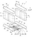
図1に示される本実施形態に係る冷媒蒸発器1は、車室内の温度を調整する車両用空調装置の蒸気圧縮式の冷凍サイクルに適用され、車室内へ送風する送風空気から吸熱して冷媒(液相冷媒)を蒸発させることで、送風空気を冷却する冷却用熱交換器である。なお、本実施形態では、送風空気が特許請求の範囲における「外部を流れる被冷却流体」に相当する。
The
冷凍サイクルは、冷媒蒸発器1以外に、図示しない圧縮機、放熱器(凝縮器)、膨張弁等を備えおり、本実施形態では、放熱器と膨張弁との間に受液器を配置するレシーバサイクルとして構成されている。
In addition to the
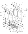
図1は、本実施形態に係る冷媒蒸発器1の模式的な斜視図であり、図2は、図1に示す冷媒蒸発器1の分解斜視図である。なお、図2では、後述する各熱交換コア部11、21におけるチューブ111、211、及びフィン112、212の図示を省略している。
FIG. 1 is a schematic perspective view of a
図1、図2に示されるように、本実施形態の冷媒蒸発器1は、送風空気の流れ方向(被冷却流体の流れ方向)Xに対して直列に配置された2つの蒸発部10、20を備えて構成されている。ここで、本実施形態では、2つの蒸発部10、20のうち、送風空気の空気流れ方向の風上側(上流側)に配置される蒸発部を風上側蒸発部10と称し、送風空気の流れ方向の風下側(下流側)に配置される蒸発部を風下側蒸発部20と称する。本実施形態における風上側蒸発部10が、特許請求の範囲の「第2蒸発部」を構成し、風下側蒸発部20が、特許請求の範囲の「第1蒸発部」を構成している。
As shown in FIG. 1 and FIG. 2, the
風上側蒸発部10及び風下側蒸発部20の基本的構成は同一であり、それぞれ熱交換コア部11、21と、熱交換コア部11、21の上下両側に配置された一対のタンク部12、13、22、23を有している。
The basic configurations of the
本実施形態では、風上側蒸発部10における熱交換コア部を風上側熱交換コア部11と称し、風下側蒸発部20における熱交換コア部を風下側熱交換コア部21と称する。また、風上側蒸発部10における一対のタンク部12、13のうち、上方側に配置されるタンク部を第1風上側タンク部12と称し、下方側に配置されるタンク部を第2風上側タンク部13と称する。同様に、風下側蒸発部20における一対のタンク部22、23のうち、上方側に配置されるタンク部を第1風下側タンク部22と称し、下方側に配置されるタンク部を第2風下側タンク部23と称する。
In this embodiment, the heat exchange core part in the
本実施形態の風上側熱交換コア部11及び風下側熱交換コア部21それぞれは、上下方向に延びる複数のチューブ111、211と、隣合うチューブ111、211の間に接合されるフィン112、212とが交互に積層配置された積層体で構成されている。以下、複数のチューブ111、211及び複数のフィン112、212の積層体における積層方向をチューブ積層方向と称する。
Each of the windward side heat
ここで、風上側熱交換コア部11は、複数のチューブ111のうち、一部のチューブ群で構成される第1風上側コア部11a、及び残部のチューブ群で構成される第2風上側コア部11bを有している。なお、本実施形態における第1風上側コア部11aが、特許請求の範囲における「第3コア部」を構成し、第2風上側コア部11bが、特許請求の範囲における「第4コア部」を構成する。
Here, the windward heat
本実施形態では、風上側熱交換コア部11を送風空気の流れ方向から見たときに、チューブ積層方向の右側に存するチューブ群で第1風上側コア部11aが構成され、チューブ積層方向の左側に存するチューブ群で第2風上側コア部11bが構成されている。
In this embodiment, when the windward heat
また、風下側熱交換コア部21は、複数のチューブ211のうち、一部のチューブ群で構成される第1風下側コア部21a、及び残部のチューブ群で構成される第2風下側コア部21bを有している。なお、本実施形態における第1風下側コア部21aが、特許請求の範囲における「第1コア部」を構成し、第2風下側コア部21bが、特許請求の範囲における「第2コア部」を構成する。
Moreover, the leeward side heat
本実施形態では、風下側熱交換コア部21を送風空気の流れ方向から見たときに、チューブ積層方向の右側に存するチューブ群で第1風下側コア部21aが構成され、チューブ積層方向の左側に存するチューブ群で第2風下側コア部21bが構成されている。なお、本実施形態では、送風空気の流れ方向から見たときに、第1風上側コア部11a及び第1風下側コア部21aそれぞれが重合(対向)するように配置されると共に、第2風上側コア部11b及び第2風下側コア部21bそれぞれが重合(対向)するように配置されている。
In the present embodiment, when the leeward heat
各チューブ111、211は、内部に冷媒が流れる冷媒通路が形成されると共に、その断面形状が送風空気の流れ方向に沿って延びる扁平形状となる扁平チューブで構成されている。
Each of the
風上側熱交換コア部11のチューブ111は、長手方向の一端側(上端側)が第1風上側タンク部12に接続されると共に、長手方向の他端側(下端側)が第2風上側タンク部13に接続されている。また、風下側熱交換コア部21のチューブ211は、長手方向の一端側(上端側)が第1風下側タンク部22に接続されると共に、長手方向の他端側(下端側)が第2風下側タンク部23に接続されている。
The
各フィン112、212は、薄板材を波上に曲げて成形したコルゲートフィンであり、チューブ111、211における平坦な外面側に接合され、送風空気と冷媒との伝熱面積を拡大させるための熱交換促進手段を構成する。
Each of the
チューブ111、211及びフィン112、212の積層体には、チューブ積層方向の両端部に、各熱交換コア部11、12を補強するサイドプレート113、213が配置されている。なお、サイドプレート113、213は、チューブ積層方向の最も外側に配置されたフィン112、212に接合されている。
In the laminated body of the
第1風上側タンク部12は、一端側(送風空気の流れ方向から見たときの左側端部)が閉塞されると共に、他端側(送風空気の流れ方向から見たときの右側端部)にタンク内部から圧縮機(図示略)の吸入側に冷媒を導出するための冷媒導出口12aが形成された筒状の部材で構成されている。この第1風上側タンク部12は、底部に各チューブ111の一端側(上端側)が挿入接合される貫通穴(図示略)が形成されている。第1風上側タンク部12は、その内部空間が風上側熱交換コア部11の各チューブ111に連通するように構成されており、風上側熱交換コア部11の各コア部11a、11bからの冷媒を集合させる冷媒集合部として機能する。
The first
第1風下側タンク部22は、一端側が閉塞されると共に、他端側にタンク内部に膨張弁(図示略)にて減圧された低圧冷媒を導入するための冷媒導入口22aが形成された筒状の部材で構成されている。この第1風下側タンク部22は、底部に各チューブ211の一端側(上端側)が挿入接合される貫通穴(図示略)が形成されている。つまり、第1風下側タンク部22は、その内部空間が風下側熱交換コア部21の各チューブ211に連通するように構成されており、風下側熱交換コア部21の各コア部21a、21bへ冷媒を分配する冷媒分配部として機能する。
The first
第2風上側タンク部13は、両端側が閉塞された筒状の部材で構成されている。この第2風上側タンク部13は、天井部に各チューブ111の他端側(下端側)が挿入接合される貫通穴(図示略)が形成されている。つまり、第2風上側タンク部13は、その内部空間が各チューブ111に連通するように構成されている。
The 2nd windward
また、第2風上側タンク部13の内部には、長手方向の中央位置に仕切部材131が配置されており、この仕切部材131によって、タンク内部空間が第1風上側コア部11aを構成する各チューブ111が連通する空間と、第2風上側コア部11bを構成する各チューブ111が連通する空間とに仕切られている。
In addition, a
ここで、第2風上側タンク部13の内部のうち、第1風上側コア部11aを構成する各チューブ111に連通する空間が、第1風上側コア部11aに冷媒を分配する第1冷媒分配部13aを構成し、第2風上側コア部11bを構成する各チューブ111に連通する空間が、第2風上側コア部11bに冷媒を分配する第2冷媒分配部13bを構成する。
Here, in the inside of the second
第2風下側タンク部23は、両端側が閉塞された筒状の部材で構成されている。この第2風下側タンク部23は、天井部に各チューブ211の他端側(下端側)が挿入接合される貫通穴(図示略)が形成されている。つまり、第2風下側タンク部23は、その内部空間が各チューブ211に連通するように構成されている。
The 2nd leeward
第2風下側タンク部23の内部には、長手方向の中央位置に仕切部材231が配置されており、この仕切部材231によって、タンク内部空間が第1風下側コア部21aを構成する各チューブ211が連通する空間と、第2風下側コア部21bを構成する各チューブ211が連通する空間とに仕切られている。
Inside the second
ここで、第2風下側タンク部23の内部のうち、第1風下側コア部21aを構成する各チューブ211に連通する空間が、第1風下側コア部21aからの冷媒を集合させる第1冷媒集合部23aを構成し、第2風下側コア部21bを構成する各チューブ211が連通する空間が、第2風下側コア部21bからの冷媒を集合させる第2冷媒集合部23bを構成する。
Here, in the inside of the second leeward
第2風上側タンク部13、及び第2風下側タンク部23それぞれは、冷媒入替部30を介して連結されている。この冷媒入替部30は、第2風下側タンク部23における第1冷媒集合部23a内の冷媒を第2風上側タンク部13における第2冷媒分配部13bに導くと共に、第2風下側タンク部23における第2冷媒集合部23b内の冷媒を第2風上側タンク部13における第1冷媒分配部13aに導くように構成されている。すなわち、冷媒入替部30は、冷媒の流れを各熱交換コア部11、21においてコア幅方向に入れ替えるように構成されている。
The second
具体的には、冷媒入替部30は、第2風下側タンク部23における第1、第2冷媒集合部23a、23bに連結された一対の集合部連結部材31a、31bと、第2風上側タンク部13における各冷媒分配部13a、13bに連結された一対の分配部連結部材32a、32bと、一対の集合部連結部材31a、31b及び一対の分配部連結部材32a、32bそれぞれに連結された中間タンク部33と、を有して構成されている。
Specifically, the
一対の集合部連結部材31a、31bそれぞれは、内部に冷媒が流通する冷媒通路が形成された筒状の部材で構成されており、その一端側が第2風下側タンク部23に接続されると共に、他端側が中間タンク部33に接続されている。本実施形態における集合部連結部材31aが、特許請求の範囲の「第1流入流路」を構成し、集合部連結部材31bが、特許請求の範囲の「第2流入流路」を構成している。
Each of the pair of assembly
一対の集合部連結部材31a、31bのうち、一方を構成する第1集合部連結部材31aは、一端側が第1冷媒集合部23aに連通するように第2風下側タンク部23に接続されており、他端側が後述する中間タンク部33内の第1冷媒通路33aに連通するように中間タンク部33に接続されている。本実施形態における第1冷媒通路33aが、特許請求の範囲の「第1中継流路」を構成している。
The first collecting
また、他方を構成する第2集合部連結部材31bは、一端側が第2冷媒集合部23bに連通するように第2風下側タンク部23に接続されており、他端側が後述する中間タンク部33内の第2冷媒通路33bに連通するように中間タンク部33に接続されている。本実施形態における第2冷媒通路33bが、特許請求の範囲の「第2中継流路」を構成している。
Further, the second collecting
本実施形態では、第1集合部連結部材31aの一端側が、第1冷媒集合部23aのうち、仕切部材231に近い位置に接続され、第2集合部連結部材31bの一端側が、第2冷媒集合部23bのうち、第2風下側タンク部23の閉塞端に近い位置に接続されている。
In the present embodiment, one end side of the first collecting
一対の分配部連結部材32a、32bそれぞれは、内部に冷媒が流通する冷媒通路が形成された筒状の部材で構成されており、その一端側が第2風上側タンク部13に接続されると共に、他端側が中間タンク部33に接続されている。本実施形態における分配部連結部材32aが、特許請求の範囲の「第2流出流路」を構成し、分配部連結部材32bが、特許請求の範囲の「第1流出流路」を構成している。
Each of the pair of distribution
一対の分配部連結部材32a、32bのうち、一方を構成する第1分配部連結部材32aは、一端側が第1冷媒分配部13aに連通するように第2風上側タンク部13に接続されており、他端側が後述する中間タンク部33内の第2冷媒通路33bに連通するように中間タンク部33に接続されている。すなわち、第1分配部連結部材32aは、中間タンク部33の第2冷媒通路33bを介して、上述の第2集合部連結部材31bと連通している。
Of the pair of
一対の分配部連結部材32a、32bのうち、他方を構成する第2分配部連結部材32bは、一端側が第2冷媒分配部13bに連通するように第2風上側タンク部13に接続されており、他端側が後述する中間タンク部33内の第1冷媒通路33aに連通するように中間タンク部33に接続されている。すなわち、第2分配部連結部材32bは、中間タンク部33の第1冷媒通路33aを介して、上述の第1集合部連結部材31aと連通している。
Of the pair of distribution
本実施形態では、第1分配部連結部材32aの一端側が、第1冷媒分配部13aのうち、第2風上側タンク部13の閉塞端に近い位置に接続され、第2分配部連結部材32bの一端側が、第2冷媒分配部13bのうち、仕切部材131に近い位置に接続されている。
In the present embodiment, one end side of the first distribution
このように構成される一対の集合部連結部材31a、31bそれぞれは、冷媒入替部30における冷媒の流入口を構成し、一対の分配部連結部材32a、32bそれぞれは、冷媒入替部30における冷媒の流出口を構成している。
Each of the pair of collecting
風上側熱交換コア部11における各コア部11a、11bでは、各コア部11a、11bを構成する複数のチューブ111のうち、積層方向の端部側に位置するチューブへ冷媒が流れ難く、冷媒の分配性が悪いといった傾向がある。
In each
具体的には、第1風上側コア部11aでは、第2風上側タンク部13の第1冷媒分配部13aにおける閉塞された端部付近に位置するチューブ111、及び仕切部材131付近に位置するチューブ111に冷媒が流れ難い傾向がある。また、第2風上側コア部11bでは、第2風上側タンク部13の第2冷媒分配部13bにおける閉塞された端部付近に位置するチューブ111、及び仕切部材131付近に位置するチューブ111に冷媒が流れ難い傾向がある。
Specifically, in the first
そこで、本実施形態では、各分配部連結部材32a、32bを、第1風上側コア部11aを構成する複数のチューブ111のうち、積層方向一端側に位置するチューブと対向するように開口する構成としている。
Therefore, in the present embodiment, each distribution
図4は、第1分配部連結部材32a及び第2分配部連結部材32b近傍の冷媒の流れを示す図であって、(A)は模式的な断面図を示し、(B)は模式的な側面図を示す。図4に示されるように、第1分配部連結部材32aについては、その開口部が第1風上側コア部11aを構成する複数のチューブ111のうち、積層方向一端側に位置するチューブと対向して開口するように、第1冷媒分配部13aのうち、第2風上側タンク部13の閉塞端に近い位置に接続している。第1分配部連結部材32aは、第2冷媒通路33bの側壁部33baに繋がれている。第1分配部連結部材32aは、第2冷媒通路33bの一端壁部33bbに近接し、他端壁部33bcからは離間して設けられている。
4A and 4B are diagrams showing the flow of the refrigerant in the vicinity of the first
第2集合部連結部材31bを通って第2冷媒通路33bに流れ込む冷媒は、他端壁部33bc側に流れこむ。他端壁部33bc側に流れ込んだ冷媒は、一端壁部33bbに向かって流れ、一端壁部33bbに当たって流れを変え、側壁部33baに沿って一端壁部33bbから他端壁部33bcに向かって流れながら第1分配部連結部材32aに流出するように構成されている。この冷媒の流出段階に着目すると、第2中継流路である第2冷媒流路33bにおいて冷媒は、一端側である一端壁部33bbから他端側である他端壁部bcに向かって流れながら第2流出流路である第1分配部連結部材32aに流出する。
The refrigerant that flows into the second
本実施形態の場合、第1分配部連結部材32aは、一端側である一端壁部33bb側が冷媒の流れ方向に対して幅狭で、他端側である他端壁部33bc側が幅広になるように構成されている。このような構成により、第1分配部連結部材32aには、一端側である一端壁部33bb側に冷媒が流出し難い第1流出領域が形成されると共に、その第1流出領域よりも他端側である他端壁部33bc側に冷媒が流出し易い第2流出領域が形成されていることになる。
In the case of the present embodiment, the first distribution
一方、第2分配部連結部材32bについては、第2風上側コア部11bを構成する複数のチューブ111のうち、積層方向一端側に位置するチューブと対向して開口するように、第2冷媒分配部13bのうち、仕切部材131に近い位置に接続している。
On the other hand, about the 2nd distribution
第2分配部連結部材32bは、第1冷媒通路33aの側壁部33aaに繋がれている。第2分配部連結部材32bは、第1冷媒通路33aの一端壁部33abに近接し、他端壁部33acからは離間して設けられている。
The 2nd distribution
第1集合部連結部材31aを通って第1冷媒通路33aに流れ込む冷媒は、一端壁部33ab側に流れこむ。一端壁部33ab側に流れ込んだ冷媒は、他端壁部33acに向かって流れ、側壁部33aaに沿って一端壁部33abから他端壁部33acに向かって流れながら第2分配部連結部材32bに流出するように構成されている。この冷媒の流出段階に着目すると、第1中継流路である第1冷媒流路33aにおいて冷媒は、一端側である一端壁部33abから他端側である他端壁部acに向かって流れながら第1流出流路である第2分配部連結部材32bに流出する。
The refrigerant flowing into the first
本実施形態の場合、第2分配部連結部材32bは、一端側である一端壁部33ab側が冷媒の流れ方向に対して幅狭で、他端側である他端壁部33ac側が幅広になるように構成されている。このような構成により、第2分配部連結部材32bには、一端側である一端壁部33ab側に冷媒が流出し難い第1流出領域が形成されると共に、その第1流出領域よりも他端側である他端壁部33ac側に冷媒が流出し易い第2流出領域が形成されていることになる。
In the case of the present embodiment, the second distribution
中間タンク部33は、両端側が閉塞された筒状の部材で構成されている。この中間タンク部33は、第2風上側タンク部13、及び第2風下側タンク部23との間に配置されている。具体的には、本実施形態の中間タンク部33は、送風空気の流れ方向Xから見たときに、その一部(上方側の部位)が第2風上側タンク部13、及び第2風下側タンク部23と重合し、他部(下方側の部位)が第2風上側タンク部13、及び第2風下側タンク部23と重合しないように配置されている。
The
このように、中間タンク部33の一部を第2風上側タンク部13、及び第2風下側タンク部23と重合しないように配置する構成とすれば、送風空気の流れ方向Xにおいて、第1蒸発部10及び第2蒸発部20を近接した配置形態とすることができるので、中間タンク部33を設けることによる冷媒蒸発器1の体格の増大を抑制することが可能となる。
Thus, if it is set as the structure arrange | positioned so that a part of intermediate |
ここで、本実施形態では、第1集合部連結部材31a、第2分配部連結部材32b、中間タンク部33における第1冷媒通路33aが、特許請求の範囲に記載の「第1連通部」を構成している。そして、第1集合部連結部材31aが「第1連通部」における「冷媒の流入口」に相当し、第2分配部連結部材32bが「第1連通部」における「冷媒の流出口」に相当している。
Here, in the present embodiment, the first
第2集合部連結部材31b、第1分配部連結部材32a、中間タンク部33における第2冷媒通路33bが、特許請求の範囲に記載の「第2連通部」を構成している。そして、第2集合部連結部材31bが「第2連通部」における「冷媒の流入口」に相当し、第1分配部連結部材32aが「第2連通部」における「冷媒の流出口」に相当している。
The second collecting
次に、本実施形態に係る冷媒蒸発器1における冷媒の流れについて図3を用いて説明する。図3は、本実施形態に係る冷媒蒸発器1における冷媒の流れを説明するための説明図である。
Next, the flow of the refrigerant in the
図3に示すように、膨張弁(図示略)にて減圧された低圧冷媒は、矢印Aの如く第1風下側タンク部22の一端側に形成された冷媒導入口22aからタンク内部に導入される。第1風下側タンク部22の内部に導入された冷媒は、矢印Bの如く風下側熱交換コア部21の第1風下側コア部21aを下降すると共に、矢印Cの如く風下側熱交換コア部21の第2風下側コア部21bを下降する。
As shown in FIG. 3, the low-pressure refrigerant decompressed by an expansion valve (not shown) is introduced into the tank through a
第1風下側コア部21aを下降した冷媒は、矢印Dの如く第2風下側タンク部23の第1冷媒集合部23aに流入する。一方、第2風下側コア部21bを下降した冷媒は、矢印Eの如く第2風下側タンク部23の第2冷媒集合部23bに流入する。
The refrigerant descending the first
第1冷媒集合部23aに流入した冷媒は、矢印Fの如く第1集合部連結部材31aを介して中間タンク部33の第1冷媒通路33aに流入する。また、第2冷媒集合部23bに流入した冷媒は、矢印Gの如く第2集合部連結部材31bを介して中間タンク部33の第2冷媒通路33bに流入する。
The refrigerant that has flowed into the first
第1冷媒通路33aに流入した冷媒は、矢印Hの如く第2分配部連結部材32bを介して第2風上側タンク部13の第2冷媒分配部13bに流入する。また、第2冷媒通路33bに流入した冷媒は、矢印Iの如く第1分配部連結部材32aを介して第2風上側タンク部13の第1冷媒分配部13aに流入する。
The refrigerant flowing into the first
第2風上側タンク部13の第2冷媒分配部13bに流入した冷媒は、矢印Jの如く風上側熱交換コア部11の第2風上側コア部11bを上昇する。一方、第1冷媒分配部13aに流入した冷媒は、矢印Kの如く風上側熱交換コア部11の第1風上側コア部11aを上昇する。
The refrigerant that has flowed into the second
第2風上側コア部11bを上昇した冷媒、及び第1風上側コア部11aを上昇した冷媒は、それぞれ矢印L、Mの如く第1風上側タンク部12のタンク内部に流入し、矢印Nの如く第1風上側タンク部12の一端側に形成された冷媒導出口12aから圧縮機(図示略)吸入側に導出される。
The refrigerant rising up the second
以上説明した本実施形態に係る冷媒蒸発器1では、冷媒入替部30における各連通部の冷媒の流出口を構成する各分配部連結部材32a、32bのチューブ積層方向に交わる方向の開口幅が、開口部分の冷媒流れの前流側よりも後流側が広い部分が形成されるように設けられている。
In the
これにより、風上側蒸発部10における第2風上側タンク部13の各冷媒分配部13a、13bから風上側熱交換コア部11の各コア部11a、11bへの液相冷媒の分配の偏りを抑制することができる。この結果、冷媒蒸発器1における送風空気の冷却性能の低下を抑制することが可能となる。
This suppresses the bias in the distribution of the liquid-phase refrigerant from the respective
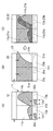
ここで、図6は、比較例に係る冷媒蒸発器1(図5に示されるような、開口幅が変化しない各分配部連結部材32aF、32bFを有するもの)の各熱交換コア部11、21を流れる液相冷媒の分布を説明するための説明図であり、図7は、本実施形態に係る冷媒蒸発器1の各熱交換コア部11、21を流れる液相冷媒の分布を説明するための説明図である。尚、本実施形態の各分配部連結部材32a、32bの幅Lb1、Lb2と、比較例地の各分配部連結部材32aF、32bFの幅Lb1、Lb2とは同じ幅である。
Here, FIG. 6 shows the heat
図6(A)及び図7(A)は、風上側熱交換コア部11を流れる液相冷媒の分布を示し、図6(B)及び図7(B)は、風下側熱交換コア部21を流れる液相冷媒の分布を示し、図6(C)及び図7(C)は、各熱交換コア部11、21を流れる液相冷媒の分布の合成を示している。なお、図6及び図7は、冷媒蒸発器1を図1の矢印Y方向(送風空気の流れ方向Yの逆方向)から見たときの液相冷媒の分布を示すもので、図中の斜線部分で示す箇所が、液相冷媒が存する部分を示す。
FIGS. 6 (A) and 7 (A) show the distribution of the liquid-phase refrigerant flowing through the windward heat
まず、風下側熱交換コア部21を流れる液相冷媒の分布については、図6(B)及び図7(B)で示すように、比較例に係る冷媒蒸発器1と本実施形態に係る冷媒蒸発器1とで同様であり、冷媒の流速が低い場合、それぞれ第2風下側コア部21bにおける一部に液相冷媒が流れ難い箇所(図中右下方側の白抜き箇所)が生ずる。
First, regarding the distribution of the liquid-phase refrigerant flowing through the leeward heat
一方、比較例に係る冷媒蒸発器1における風上側熱交換コア部11を流れる液相冷媒の分布については、図6(A)に示すように、風上側熱交換コア部11の各風上側コア部11a、11bでは、チューブ積層方向において、各分配部連結部材32aF、32bFが形成された側に液相冷媒が流れ易く、各分配部連結部材32aF、32bFが形成されていない側に液相冷媒が流れ難くなっている。
On the other hand, regarding the distribution of the liquid-phase refrigerant flowing through the windward heat
そして、図6(C)に示すように、比較例に係る冷媒蒸発器1を送風空気の流れ方向Xから見たときに、第2風上側コア部11b及び第2風下側コア部21bにおける重合する部位の一部に液相冷媒が流れ難い箇所(図中右側の白抜き箇所)が生ずる。
As shown in FIG. 6C, when the
このように液相冷媒が分布する比較例に係る冷媒蒸発器1では、液相冷媒が流れ難い箇所にて冷媒が送風空気から顕熱分を吸熱するだけで送風空気を充分に冷却することができない。この結果、冷媒蒸発器1を通過する送風空気に温度分布が生じてしまうこととなる。
As described above, in the
これに対して、本実施形態に係る冷媒蒸発器1における風上側熱交換コア部11を流れる液相冷媒の分布については、各分配部連結部材32a、32bのチューブ積層方向に交わる方向に開口幅が増大していくようにしているので、図7(A)に示すように、風上側熱交換コア部11の各風上側コア部11a、11bでは、チューブ積層方向に均等に液相冷媒が流れ易くなっている。つまり、本実施形態に係る冷媒蒸発器1は、風上側熱交換コア部11の各コア部11a、11bへの液相冷媒の分配の偏りが抑制されることとなる。
On the other hand, with respect to the distribution of the liquid-phase refrigerant flowing through the windward heat
そして、図8(C)に示すように、本実施形態に係る冷媒蒸発器1を送風空気の流れ方向Xから見たときに、第2風上側コア部11b及び第2風下側コア部21bにおける重合する部位の全域に液相冷媒が流れる。
And when the
このように液相冷媒が分布する本実施形態に係る冷媒蒸発器1では、各熱交換コア部11、21のいずれかによって、冷媒が送風空気から顕熱及び潜熱を吸熱するので、送風空気を充分に冷却することが可能となる。この結果、冷媒蒸発器1を通過する送風空気に温度分布が生じてしまうことが抑制される。
In the
ところで、各分配部連結部材32a、32bの形状は、上記説明した形状に限られるものではなく、各分配部連結部材32a、32bに流れ込む付近の冷媒流れ方向の前流側(一端壁33ab、33bb側)に冷媒が流れ込み難い第1流出領域が形成され、後流側(他端壁33ac、33bc側)に冷媒が流れ込み易い第2流出領域が形成されればよいものである。
By the way, the shape of each distribution
図8は、第1分配部連結部材32aを(A)に示し、その変形例を(B)から(G)に示したものである。第1分配部連結部材32aを例に説明するけれども、第2分配部連結部材32bでも同様である。
FIG. 8 shows the first
(B)では、流出領域32aAaと、流出領域32aAbと、流出領域32aAcとを有する第1分配部連結部材32aAを示している。各流出領域の流路断面積は、流出領域32aAaが一番狭く、流出領域32aAcが一番広い。従って、流出領域32aAaが第1流出領域として形成され、流出領域32aAcが第2流出領域として形成されている。流出領域32aAbの流路断面積は、流出領域32aAaと流出領域32aAcとの中間に設定されているけれども、いずれかの流路断面積と略同等でも構わず、流出領域32aAaより狭くても構わない。 In (B), 1st distribution part connection member 32aA which has outflow area | region 32aAa, outflow area | region 32aAb, and outflow area | region 32aAc is shown. The flow passage cross-sectional area of each outflow region is the narrowest in the outflow region 32aAa and the widest in the outflow region 32aAc. Accordingly, the outflow region 32aAa is formed as the first outflow region, and the outflow region 32aAc is formed as the second outflow region. The cross-sectional area of the outflow region 32aAb is set in the middle between the outflow region 32aAa and the outflow region 32aAc, but may be substantially the same as any of the cross-sectional areas of the flow regions or may be narrower than the outflow region 32aAa. .
(C)では、流出領域32aBaと、流出領域32aBbとを有する第1分配部連結部材32aBを示している。流出領域32aBaが狭く、流出領域32aBbが広い。従って、流出領域32aBaが第1流出領域として形成され、流出領域32aBbが第2流出領域として形成されている。 In (C), the 1st distribution part connection member 32aB which has outflow area 32aBa and outflow area 32aBb is shown. The outflow region 32aBa is narrow and the outflow region 32aBb is wide. Accordingly, the outflow region 32aBa is formed as the first outflow region, and the outflow region 32aBb is formed as the second outflow region.
(D)では、流出領域32aCaと、流出領域32aCbと、流出領域32aCcとを有する第1分配部連結部材32aCを示している。各流出領域の流路断面積は、流出領域32aCaが一番狭く、流出領域32aCcが一番広い。従って、流出領域32aCaが第1流出領域として形成され、流出領域32aCcが第2流出領域として形成されている。流出領域32aCbの流路断面積は、流出領域32aCaと流出領域32aCcとの中間に設定されているけれども、いずれかの流路断面積と略同等でも構わず、流出領域32aCaより狭くても構わない。また、流出領域32aCbの流路断面積が、流出領域32aCaと流出領域32aCcとの中間に設定されている場合、流出領域32aCaとの関係では流出領域32aCbが第2流出領域として形成されており、流出領域32aCcとの関係では流出領域32aCbが第1流出領域として形成されていることになる。 In (D), the 1st distribution part connection member 32aC which has outflow area | region 32aCa, outflow area | region 32aCb, and outflow area | region 32aCc is shown. The flow passage cross-sectional area of each outflow region is the narrowest in the outflow region 32aCa and the widest in the outflow region 32aCc. Accordingly, the outflow region 32aCa is formed as the first outflow region, and the outflow region 32aCc is formed as the second outflow region. The cross-sectional area of the outflow region 32aCb is set in the middle between the outflow region 32aCa and the outflow region 32aCc. . In addition, when the cross-sectional area of the outflow region 32aCb is set between the outflow region 32aCa and the outflow region 32aCc, the outflow region 32aCb is formed as the second outflow region in relation to the outflow region 32aCa. In relation to the outflow region 32aCc, the outflow region 32aCb is formed as the first outflow region.
(E)では、流出領域32aDaと、流出領域32aDbと、流出領域32aDcとを有する第1分配部連結部材32aDを示している。流出領域32aDa、流出領域32aDb、及び流出領域32aDcは、同じ流路断面積の円状流出口の個数を変えることで構成されている。流出領域32aDaは1つの円状流出口で構成され、流出領域32aDbは2つの円状流出口で構成され、流出領域32aDcは3つの円状流出口で構成されている。従って、流出領域32aDaが第1流出領域として形成され、流出領域32aDcが第2流出領域として形成されている。流出領域32aDaとの関係では流出領域32aDbが第2流出領域として形成されており、流出領域32aDcとの関係では流出領域32aDbが第1流出領域として形成されていることになる。 In (E), the 1st distribution part connection member 32aD which has outflow area 32aDa, outflow area 32aDb, and outflow area 32aDc is shown. The outflow region 32aDa, the outflow region 32aDb, and the outflow region 32aDc are configured by changing the number of circular outflow ports having the same flow path cross-sectional area. The outflow region 32aDa is composed of one circular outlet, the outflow region 32aDb is composed of two circular outlets, and the outflow region 32aDc is composed of three circular outlets. Accordingly, the outflow region 32aDa is formed as the first outflow region, and the outflow region 32aDc is formed as the second outflow region. The outflow region 32aDb is formed as the second outflow region in relation to the outflow region 32aDa, and the outflow region 32aDb is formed as the first outflow region in relation to the outflow region 32aDc.
(F)では、流出領域32aEaと、流出領域32aEbと、流出領域32aEcとを有する第1分配部連結部材32aEを示している。流出領域32aEaは流出領域32aDaに対応し、流出領域32aEbは流出領域32aDbに対応し、流出領域32aEcは流出領域32aDcに対応している。流出領域32aEaは、流出領域32aDaと同一形状である。流出領域32aEb及び流出領域32aEcは、流出領域32aDb及び流出領域32aDcの外周を結んだ長円形状をなしている。 In (F), the 1st distribution part connection member 32aE which has outflow area 32aEa, outflow area 32aEb, and outflow area 32aEc is shown. The outflow region 32aEa corresponds to the outflow region 32aDa, the outflow region 32aEb corresponds to the outflow region 32aDb, and the outflow region 32aEc corresponds to the outflow region 32aDc. The outflow region 32aEa has the same shape as the outflow region 32aDa. The outflow region 32aEb and the outflow region 32aEc have an oval shape connecting the outer peripheries of the outflow region 32aDb and the outflow region 32aDc.
(G)では、流出領域32aFaと、流出領域32aFbと、流出領域32aFcとを有する第1分配部連結部材32aFを示している。流出領域32aFaは流出領域32aEaに対応し、流出領域32aFbは流出領域32aEbに対応し、流出領域32aFcは流出領域32aEcに対応している。流出領域32aFaは、流出領域32aEaと同一形状である。流出領域32aFb及び流出領域32aFcは、流出領域32aEb及び流出領域32aEcに仕切りを設けた形状をなしている。 In (G), the 1st distribution part connection member 32aF which has the outflow area | region 32aFa, the outflow area | region 32aFb, and the outflow area | region 32aFc is shown. The outflow region 32aFa corresponds to the outflow region 32aEa, the outflow region 32aFb corresponds to the outflow region 32aEb, and the outflow region 32aFc corresponds to the outflow region 32aEc. The outflow region 32aFa has the same shape as the outflow region 32aEa. The outflow region 32aFb and the outflow region 32aFc have a shape in which a partition is provided in the outflow region 32aEb and the outflow region 32aEc.
尚、上述した本実施形態では、風上側熱交換コア部11を2つに分割して風上側コア部11a,11bとし、風下側熱交換コア部21を2分割して風下側コア部21a,21bとしたが、コアの分割態様はこれに限られるものではない。風上側熱交換コア部11や風下側熱交換コア部21を3つ以上に分割してもよい。また、風上側熱交換コア部11及び風下側熱交換コア部21を同数に分割するのではなく、互いに異なる個数に分割してもよい。例えば、風上側熱交換コア部11を2つに分割し、風下側熱交換コア部21を3つに分割してもよい。
In the present embodiment described above, the windward side heat
1:冷媒蒸発器
10:風上側蒸発部(第2蒸発部)
11:風上側熱交換コア部(熱交換コア部)
111:チューブ
11a:風上側コア部(第3コア部)
11b:風上側コア部(第4コア部)
12:風上側タンク部(タンク部)
13:風上側タンク部(タンク部)
13a:第1冷媒分配部
13b:第2冷媒分配部
20:風下側蒸発部(第1蒸発部)
21:風下側熱交換コア部(熱交換コア部)
211:チューブ
21a:風下側コア部(第1コア部)
21b:風下側コア部(第2コア部)
22:風下側タンク部(タンク部)
23:風下側タンク部(タンク部)
23a:第1冷媒集合部
23b:第2冷媒集合部
30:冷媒入替部
31a:第1集合部連結部材(第1流入流路(第1連通部))
31b:第2集合部連結部材(第2流入流路(第2連通部))
32a:第1分配部連結部材(第2流出流路(第2連通部))
32b:第2分配部連結部材(第1流出流路(第1連通部))
33:中間タンク部
33a:第1冷媒通路(第1中継流路)
33b:第2冷媒通路(第2中継流路)
1: Refrigerant evaporator 10: Upwind evaporator (second evaporator)
11: Windward side heat exchange core part (heat exchange core part)
111:
11b: Windward core (fourth core)
12: Upwind tank (tank)
13: Upwind tank (tank)
13a: first
21: Downward heat exchange core (heat exchange core)
211:
21b: Downward core part (second core part)
22: Downward tank part (tank part)
23: Downward tank part (tank part)
23a: 1st refrigerant |
31b: 2nd gathering part connection member (2nd inflow channel (2nd communication part))
32a: 1st distribution part connection member (2nd outflow channel (2nd communication part))
32b: 2nd distribution part connection member (1st outflow channel (1st communication part))
33:
33b: second refrigerant passage (second relay flow path)
Claims (3)
前記被冷却流体の流れ方向に対して直列に配置された第1蒸発部(20)、及び第2蒸発部(10)を備え、
前記第1蒸発部及び前記第2蒸発部はそれぞれ、
冷媒が流れる複数のチューブ(111、211)を積層して構成された熱交換コア部(11、21)と、
前記複数のチューブの両端部に接続され、前記複数のチューブを流れる冷媒の集合又は分配を行う一対のタンク部(12、13、22、23)と、を有し、
前記第1蒸発部における前記熱交換コア部(21)は、前記複数のチューブ(211)のうち一部のチューブ群で構成される第1コア部(21a)、及び残部のチューブ群のうち少なくとも一部のチューブ群で構成される第2コア部(21b)を有し、
前記第2蒸発部における前記熱交換コア部(11)は、前記複数のチューブ(211)のうち一部のチューブ群で構成される前記第1コア部の少なくとも一部と対向するチューブ群で構成される第3コア部(11a)、及び残部のチューブ群のうち少なくとも一部のチューブ群で構成される第4コア部(11b)を有し、
前記第1蒸発部における前記一対のタンク部(22、23)のうち、一方のタンク部(23)は、前記第1コア部からの冷媒を集合させる第1冷媒集合部(23a)、前記第2コア部(21b)からの冷媒を集合させる第2冷媒集合部(23b)を含んで構成され、
前記第2蒸発部における前記一対のタンク部(12、13)のうち、一方のタンク部(13)は、前記第3コア部に冷媒を分配させる第1冷媒分配部(13a)、前記第4コア部(11b)に冷媒を分配させる第2冷媒分配部(13b)を含んで構成され、
前記第1蒸発部及び前記第2蒸発部は、前記第1冷媒集合部の冷媒を前記第2冷媒分配部に導く第1連通部(31a、32b、33a)、及び前記第2冷媒集合部の冷媒を前記第1冷媒分配部に導く第2連通部(31b、32a、33b)を有する冷媒入替部(30)を介して連結されており、
前記冷媒入替部は、中間タンク部(33)を有しており、
前記中間タンク部は、
前記第1冷媒集合部とは冷媒の第1流入流路(31a)を介して繋がり、前記第2冷媒分配部とは冷媒の第1流出流路(32b)を介して繋がる第1中継流路(33a)と、
前記第2冷媒集合部とは冷媒の第2流入流路(31b)を介して繋がり、前記第1冷媒分配部とは冷媒の第2流出流路(32a)を介して繋がる第2中継流路(33b)と、を有し、
前記第1中継流路及び前記第2中継流路において冷媒は、一端側から他端側に向かって流れながら前記第1流出流路及び前記第2流出流路に流出するように構成されており、
前記第1流出流路及び前記第2流出流路にはそれぞれ、冷媒が流出し難い第1流出領域が前記一端側に形成されると共に、前記第1流出領域よりも前記他端側に冷媒が流出し易い第2流出領域が形成されていることを特徴とする冷媒蒸発器。 A refrigerant evaporator (1) for exchanging heat between a fluid to be cooled flowing outside and a refrigerant,
A first evaporator (20) and a second evaporator (10) arranged in series with respect to the flow direction of the fluid to be cooled;
The first evaporator and the second evaporator are respectively
A heat exchange core (11, 21) configured by laminating a plurality of tubes (111, 211) through which refrigerant flows;
A pair of tank parts (12, 13, 22, 23) connected to both ends of the plurality of tubes and collecting or distributing refrigerant flowing through the plurality of tubes;
The heat exchange core part (21) in the first evaporation part is at least one of a first core part (21a) constituted by a part of the tube groups of the plurality of tubes (211) and a remaining tube group. It has a second core part (21b) composed of a part of a tube group,
The heat exchange core part (11) in the second evaporation part is composed of a tube group facing at least a part of the first core part composed of a part of the plurality of tubes (211). The third core portion (11a), and the fourth core portion (11b) composed of at least a part of the remaining tube groups.
Of the pair of tank parts (22, 23) in the first evaporation part, one tank part (23) is a first refrigerant assembly part (23a) for collecting refrigerant from the first core part, the first A second refrigerant assembly part (23b) for collecting refrigerant from the two core parts (21b),
Of the pair of tank parts (12, 13) in the second evaporation part, one tank part (13) is a first refrigerant distribution part (13a) for distributing refrigerant to the third core part, and the fourth A second refrigerant distributor (13b) that distributes the refrigerant to the core (11b);
The first evaporating unit and the second evaporating unit include a first communication unit (31a, 32b, 33a) for guiding the refrigerant of the first refrigerant collecting unit to the second refrigerant distributing unit, and the second refrigerant collecting unit. It is connected via a refrigerant replacement part (30) having a second communication part (31b, 32a, 33b) for guiding the refrigerant to the first refrigerant distribution part,
The refrigerant replacement part has an intermediate tank part (33),
The intermediate tank portion is
The first refrigerant flow path is connected to the first refrigerant collecting section through a first refrigerant flow-in path (31a), and the second refrigerant distribution section is connected to the first refrigerant flow-out path (32b). (33a)
A second relay flow path connected to the second refrigerant collecting section via a second refrigerant flow-in flow path (31b) and a first refrigerant distribution section connected to the second refrigerant distribution section via a second refrigerant flow-out flow path (32a). (33b)
In the first relay flow path and the second relay flow path, the refrigerant flows out from the one end side toward the other end side and flows out to the first outflow path and the second outflow path. ,
In each of the first outflow channel and the second outflow channel, a first outflow region where the refrigerant does not easily flow out is formed on the one end side, and the refrigerant is disposed on the other end side of the first outflow region. The refrigerant | coolant evaporator characterized by the 2nd outflow area | region easy to flow out being formed.
前記第1流出領域に含まれる前記開口部の数よりも、前記第2流出領域に含まれる前記開口部の数が多いことを特徴とする請求項1に記載の冷媒蒸発器。 At least one of the first outflow region and the second outflow region is constituted by one or a plurality of openings,
2. The refrigerant evaporator according to claim 1, wherein the number of the openings included in the second outflow region is larger than the number of the openings included in the first outflow region.
Priority Applications (1)
| Application Number | Priority Date | Filing Date | Title |
|---|---|---|---|
| JP2015114758A JP2017003140A (en) | 2015-06-05 | 2015-06-05 | Refrigerant evaporator |
Applications Claiming Priority (1)
| Application Number | Priority Date | Filing Date | Title |
|---|---|---|---|
| JP2015114758A JP2017003140A (en) | 2015-06-05 | 2015-06-05 | Refrigerant evaporator |
Publications (1)
| Publication Number | Publication Date |
|---|---|
| JP2017003140A true JP2017003140A (en) | 2017-01-05 |
Family
ID=57753747
Family Applications (1)
| Application Number | Title | Priority Date | Filing Date |
|---|---|---|---|
| JP2015114758A Pending JP2017003140A (en) | 2015-06-05 | 2015-06-05 | Refrigerant evaporator |
Country Status (1)
| Country | Link |
|---|---|
| JP (1) | JP2017003140A (en) |
Cited By (1)
| Publication number | Priority date | Publication date | Assignee | Title |
|---|---|---|---|---|
| WO2019026436A1 (en) * | 2017-08-02 | 2019-02-07 | 三菱重工サーマルシステムズ株式会社 | Heat exchanger |
Citations (7)
| Publication number | Priority date | Publication date | Assignee | Title |
|---|---|---|---|---|
| JPS5719771U (en) * | 1980-07-02 | 1982-02-01 | ||
| JP2001255095A (en) * | 2000-03-15 | 2001-09-21 | Zexel Valeo Climate Control Corp | Heat exchanger |
| JP4124136B2 (en) * | 2003-04-21 | 2008-07-23 | 株式会社デンソー | Refrigerant evaporator |
| US20110139413A1 (en) * | 2009-12-15 | 2011-06-16 | Delphi Technologies, Inc. | Flow distributor for a heat exchanger assembly |
| JP2013057426A (en) * | 2011-09-07 | 2013-03-28 | Hitachi Appliances Inc | Plate-type heat exchanger and freezing cycle device with the same |
| JP2013096653A (en) * | 2011-11-01 | 2013-05-20 | Denso Corp | Refrigerant evaporator |
| JP2013185723A (en) * | 2012-03-06 | 2013-09-19 | Denso Corp | Refrigerant evaporator |
-
2015
- 2015-06-05 JP JP2015114758A patent/JP2017003140A/en active Pending
Patent Citations (7)
| Publication number | Priority date | Publication date | Assignee | Title |
|---|---|---|---|---|
| JPS5719771U (en) * | 1980-07-02 | 1982-02-01 | ||
| JP2001255095A (en) * | 2000-03-15 | 2001-09-21 | Zexel Valeo Climate Control Corp | Heat exchanger |
| JP4124136B2 (en) * | 2003-04-21 | 2008-07-23 | 株式会社デンソー | Refrigerant evaporator |
| US20110139413A1 (en) * | 2009-12-15 | 2011-06-16 | Delphi Technologies, Inc. | Flow distributor for a heat exchanger assembly |
| JP2013057426A (en) * | 2011-09-07 | 2013-03-28 | Hitachi Appliances Inc | Plate-type heat exchanger and freezing cycle device with the same |
| JP2013096653A (en) * | 2011-11-01 | 2013-05-20 | Denso Corp | Refrigerant evaporator |
| JP2013185723A (en) * | 2012-03-06 | 2013-09-19 | Denso Corp | Refrigerant evaporator |
Cited By (2)
| Publication number | Priority date | Publication date | Assignee | Title |
|---|---|---|---|---|
| WO2019026436A1 (en) * | 2017-08-02 | 2019-02-07 | 三菱重工サーマルシステムズ株式会社 | Heat exchanger |
| JP2019027727A (en) * | 2017-08-02 | 2019-02-21 | 三菱重工サーマルシステムズ株式会社 | Heat exchanger |
Similar Documents
| Publication | Publication Date | Title |
|---|---|---|
| JP5454553B2 (en) | Refrigerant evaporator | |
| JP5796518B2 (en) | Refrigerant evaporator | |
| JP6098343B2 (en) | Refrigerant evaporator | |
| WO2014188689A1 (en) | Refrigerant evaporator | |
| JP5998854B2 (en) | Refrigerant evaporator | |
| WO2013140797A1 (en) | Refrigerant evaporator | |
| JP2016130612A (en) | Refrigerant evaporator | |
| JP6131705B2 (en) | Refrigerant evaporator | |
| JP6322982B2 (en) | Refrigerant evaporator | |
| JP5195300B2 (en) | Refrigerant evaporator | |
| JP2017003140A (en) | Refrigerant evaporator | |
| JP2014228233A (en) | Refrigerant evaporator | |
| JP6098358B2 (en) | Refrigerant evaporator | |
| JP4547205B2 (en) | Evaporator | |
| WO2014181547A1 (en) | Refrigerant evaporator | |
| JP2017015363A (en) | Refrigerant evaporator | |
| JP6458617B2 (en) | Refrigerant evaporator | |
| JP2015021665A (en) | Refrigerant evaporator | |
| WO2016063519A1 (en) | Refrigerant evaporator | |
| JP2017044375A (en) | Refrigerant evaporator | |
| JP2014126271A (en) | Evaporator structure | |
| JP2017187216A (en) | Refrigerant evaporator |
Legal Events
| Date | Code | Title | Description |
|---|---|---|---|
| A621 | Written request for application examination |
Free format text: JAPANESE INTERMEDIATE CODE: A621 Effective date: 20170823 |
|
| A131 | Notification of reasons for refusal |
Free format text: JAPANESE INTERMEDIATE CODE: A131 Effective date: 20180417 |
|
| A977 | Report on retrieval |
Free format text: JAPANESE INTERMEDIATE CODE: A971007 Effective date: 20180418 |
|
| A02 | Decision of refusal |
Free format text: JAPANESE INTERMEDIATE CODE: A02 Effective date: 20181204 |