JP5998854B2 - Refrigerant evaporator - Google Patents
Refrigerant evaporator Download PDFInfo
- Publication number
- JP5998854B2 JP5998854B2 JP2012240025A JP2012240025A JP5998854B2 JP 5998854 B2 JP5998854 B2 JP 5998854B2 JP 2012240025 A JP2012240025 A JP 2012240025A JP 2012240025 A JP2012240025 A JP 2012240025A JP 5998854 B2 JP5998854 B2 JP 5998854B2
- Authority
- JP
- Japan
- Prior art keywords
- refrigerant
- tank
- core
- evaporator
- leeward
- Prior art date
- Legal status (The legal status is an assumption and is not a legal conclusion. Google has not performed a legal analysis and makes no representation as to the accuracy of the status listed.)
- Active
Links
Images


Classifications
-
- F—MECHANICAL ENGINEERING; LIGHTING; HEATING; WEAPONS; BLASTING
- F25—REFRIGERATION OR COOLING; COMBINED HEATING AND REFRIGERATION SYSTEMS; HEAT PUMP SYSTEMS; MANUFACTURE OR STORAGE OF ICE; LIQUEFACTION SOLIDIFICATION OF GASES
- F25B—REFRIGERATION MACHINES, PLANTS OR SYSTEMS; COMBINED HEATING AND REFRIGERATION SYSTEMS; HEAT PUMP SYSTEMS
- F25B39/00—Evaporators; Condensers
- F25B39/02—Evaporators
- F25B39/028—Evaporators having distributing means
-
- F—MECHANICAL ENGINEERING; LIGHTING; HEATING; WEAPONS; BLASTING
- F28—HEAT EXCHANGE IN GENERAL
- F28D—HEAT-EXCHANGE APPARATUS, NOT PROVIDED FOR IN ANOTHER SUBCLASS, IN WHICH THE HEAT-EXCHANGE MEDIA DO NOT COME INTO DIRECT CONTACT
- F28D1/00—Heat-exchange apparatus having stationary conduit assemblies for one heat-exchange medium only, the media being in contact with different sides of the conduit wall, in which the other heat-exchange medium is a large body of fluid, e.g. domestic or motor car radiators
- F28D1/02—Heat-exchange apparatus having stationary conduit assemblies for one heat-exchange medium only, the media being in contact with different sides of the conduit wall, in which the other heat-exchange medium is a large body of fluid, e.g. domestic or motor car radiators with heat-exchange conduits immersed in the body of fluid
- F28D1/04—Heat-exchange apparatus having stationary conduit assemblies for one heat-exchange medium only, the media being in contact with different sides of the conduit wall, in which the other heat-exchange medium is a large body of fluid, e.g. domestic or motor car radiators with heat-exchange conduits immersed in the body of fluid with tubular conduits
- F28D1/053—Heat-exchange apparatus having stationary conduit assemblies for one heat-exchange medium only, the media being in contact with different sides of the conduit wall, in which the other heat-exchange medium is a large body of fluid, e.g. domestic or motor car radiators with heat-exchange conduits immersed in the body of fluid with tubular conduits the conduits being straight
- F28D1/0535—Heat-exchange apparatus having stationary conduit assemblies for one heat-exchange medium only, the media being in contact with different sides of the conduit wall, in which the other heat-exchange medium is a large body of fluid, e.g. domestic or motor car radiators with heat-exchange conduits immersed in the body of fluid with tubular conduits the conduits being straight the conduits having a non-circular cross-section
- F28D1/05366—Assemblies of conduits connected to common headers, e.g. core type radiators
- F28D1/05391—Assemblies of conduits connected to common headers, e.g. core type radiators with multiple rows of conduits or with multi-channel conduits combined with a particular flow pattern, e.g. multi-row multi-stage radiators
-
- F—MECHANICAL ENGINEERING; LIGHTING; HEATING; WEAPONS; BLASTING
- F28—HEAT EXCHANGE IN GENERAL
- F28F—DETAILS OF HEAT-EXCHANGE AND HEAT-TRANSFER APPARATUS, OF GENERAL APPLICATION
- F28F9/00—Casings; Header boxes; Auxiliary supports for elements; Auxiliary members within casings
- F28F9/02—Header boxes; End plates
- F28F9/026—Header boxes; End plates with static flow control means, e.g. with means for uniformly distributing heat exchange media into conduits
- F28F9/027—Header boxes; End plates with static flow control means, e.g. with means for uniformly distributing heat exchange media into conduits in the form of distribution pipes
- F28F9/0273—Header boxes; End plates with static flow control means, e.g. with means for uniformly distributing heat exchange media into conduits in the form of distribution pipes with multiple holes
-
- F—MECHANICAL ENGINEERING; LIGHTING; HEATING; WEAPONS; BLASTING
- F28—HEAT EXCHANGE IN GENERAL
- F28F—DETAILS OF HEAT-EXCHANGE AND HEAT-TRANSFER APPARATUS, OF GENERAL APPLICATION
- F28F9/00—Casings; Header boxes; Auxiliary supports for elements; Auxiliary members within casings
- F28F9/02—Header boxes; End plates
- F28F9/026—Header boxes; End plates with static flow control means, e.g. with means for uniformly distributing heat exchange media into conduits
- F28F9/028—Header boxes; End plates with static flow control means, e.g. with means for uniformly distributing heat exchange media into conduits by using inserts for modifying the pattern of flow inside the header box, e.g. by using flow restrictors or permeable bodies or blocks with channels
-
- F—MECHANICAL ENGINEERING; LIGHTING; HEATING; WEAPONS; BLASTING
- F28—HEAT EXCHANGE IN GENERAL
- F28F—DETAILS OF HEAT-EXCHANGE AND HEAT-TRANSFER APPARATUS, OF GENERAL APPLICATION
- F28F9/00—Casings; Header boxes; Auxiliary supports for elements; Auxiliary members within casings
- F28F9/26—Arrangements for connecting different sections of heat-exchange elements, e.g. of radiators
Description
本発明は、被冷却流体から吸熱して冷媒を蒸発させることで、被冷却流体を冷却する冷媒蒸発器に関する。 The present invention relates to a refrigerant evaporator that cools a fluid to be cooled by absorbing heat from the fluid to be cooled and evaporating the refrigerant.
この種の冷媒蒸発器としては、複数のチューブを積層して構成されるコア部、および複数のチューブの両端部に接続された一対のタンク部を備える第1、第2蒸発部を被冷却流体の流れ方向に直列に配置し、各蒸発部における一方のタンク部同士を一対の連通部を介して連結する構成が知られている(例えば、特許文献1参照)。 As this type of refrigerant evaporator, the first and second evaporators including a core part configured by stacking a plurality of tubes and a pair of tank parts connected to both ends of the plurality of tubes are used as fluids to be cooled. There is known a configuration in which the tanks are arranged in series in the flow direction and one tank unit in each evaporation unit is connected to each other via a pair of communication units (for example, see Patent Document 1).
この特許文献1の冷媒蒸発器では、第1蒸発部のコア部を流れた冷媒を、各蒸発部の一方のタンク部および当該タンク部同士を連結する一対の連通部を介して第2蒸発部のコア部に流す際に、冷媒の流れをコア部の幅方向(チューブ積層方向、左右方向)で入れ替える構成としている。つまり、冷媒蒸発器は、一対の連通部のうち、一方の連通部によって、第1蒸発部のコア部の幅方向一側を流れる冷媒を第2蒸発部のコア部の幅方向他側に流すと共に、他方の連通部によって第1蒸発部のコア部の幅方向他側を流れる冷媒を第2蒸発部のコア部の幅方向一側に流すように構成されている。
In the refrigerant evaporator disclosed in
また、特許文献1の冷媒蒸発器では、一対の連通部は、冷媒流れが左右交差する交差連通部である。そして、この交差連通部は、第1蒸発部または第2蒸発部のタンク部、もしくは、第1蒸発部のタンク部と第2蒸発部のタンク部との間に設けられた中間タンクに配置されている。
Moreover, in the refrigerant evaporator of
しかしながら、上記特許文献1に記載の冷媒蒸発器のように、交差連通部を中間タンクに設ける構成とすると、中間タンクを設けたことにより冷媒蒸発器の内容積が増加するので、冷媒封入量の増加を招くことがある。
However, if the cross communication portion is provided in the intermediate tank as in the refrigerant evaporator described in
また、交差連通部を第1蒸発部または第2蒸発部のタンク部に設ける構成とすると、当該交差連通部を隣り合うチューブ間に配置する必要があるので、交差連通部の冷媒通路断面積が小さくなってしまう。このため、交差連通部を通過する際に生じる冷媒の圧力損失が大きくなり、冷媒蒸発器における被冷却流体の冷却性能が低下するおそれがある。 Further, when the cross communication portion is provided in the tank portion of the first evaporation portion or the second evaporation portion, the cross communication portion needs to be disposed between adjacent tubes, so that the refrigerant passage cross-sectional area of the cross communication portion is increased. It gets smaller. For this reason, the pressure loss of the refrigerant | coolant which arises when passing a cross communication part becomes large, and there exists a possibility that the cooling performance of the to-be-cooled fluid in a refrigerant | coolant evaporator may fall.
本発明は上記点に鑑みて、冷媒封入量の増加を抑制しつつ冷媒流れをコア部の幅方向で入れ替えることができ、さらに被冷却流体の冷却性能を向上させることができる冷媒蒸発器を提供することを目的とする。 In view of the above points, the present invention provides a refrigerant evaporator that can change the refrigerant flow in the width direction of the core while suppressing an increase in the amount of refrigerant enclosed, and can further improve the cooling performance of the fluid to be cooled. The purpose is to do.
上記目的を達成するため、請求項1に記載の発明では、被冷却流体の流れ方向に対して直列に配置された第1蒸発部(10)、および第2蒸発部(20)を備え、第1蒸発部(10)および第2蒸発部(20)それぞれは、冷媒が流れる複数のチューブ(111、211)を積層して構成されるコア部(11、21)と、複数のチューブ(111、211)の両端部に接続され、複数のチューブ(111、211)を流れる冷媒の集合あるいは分配を行う一対のタンク部(12、13、22、23)とを有し、第1蒸発部(10)におけるコア部(11)は、複数のチューブ(111)のうち、一部のチューブ群で構成される第1コア部(11a)、および残部のチューブ群で構成される第2コア部(11b)を有し、第2蒸発部(20)におけるコア部(21)は、複数のチューブ(211)のうち、被冷却流体の流れ方向において第1コア部(11a)の少なくとも一部と対向するチューブ群で構成される第3コア部(21a)、および被冷却流体の流れ方向において第2コア部(11b)の少なくとも一部と対向するチューブ群で構成される第4コア部(21b)を有し、第1蒸発部(10)における一対のタンク部(12、13)のうち、一方のタンク部(13)は、第1コア部(11a)からの冷媒を集合させる第1冷媒集合部(13a)、および第2コア部(11b)からの冷媒を集合させる第2冷媒集合部(13b)を含んで構成され、第2蒸発部(20)における一対のタンク部(22、23)のうち、一方のタンク部(23)は、第3コア部(21a)に冷媒を分配させる第1冷媒分配部(23a)、および第4コア部(21b)に冷媒を分配させる第2冷媒分配部(23b)を含んで構成され、第2冷媒集合部(13b)と第1冷媒分配部(23a)とは、第1連通部(31)を介して接続されており、第1冷媒集合部(13a)と第2冷媒分配部(23b)とは、第2連通部(32)を介して接続されており、第1蒸発部(10)の一方のタンク部(13)および第2蒸発部(20)の一方のタンク部(23)のうち、少なくとも一方のタンク部(13)の内部には、第1冷媒集合部(13a)の冷媒を第2冷媒分配部(23b)に導くとともに、第2冷媒集合部(13b)の冷媒を第1冷媒分配部(23a)に導く冷媒入替部(13c、13d)が設けられており、冷媒入替部(13c、13d)は、第1冷媒集合部(13a)からの冷媒を第2冷媒分配部(23b)へ導く冷媒流れ、および、第2冷媒集合部(13b)からの冷媒を第1冷媒分配部(23a)へ導く冷媒流れが、チューブ(111、222)の長手方向から見たときに非交差状態となるように構成されており、第1蒸発部(10)の一対のタンク部(12、13)のうち他方のタンク部(12)における、第2コア部(11b)よりも第1コア部(11a)に近い側には、他方のタンク部(12)内部に冷媒を導入するための冷媒導入部(12a)が接続されており、第2連通部(32)は、第2蒸発部(20)の一方のタンク部(23)の、チューブ(111、222)の積層方向における冷媒導入部(12a)から遠い側の端部に接続されており、複数のチューブ(111、222)は、冷媒が鉛直方向に流れるように構成されており、第1蒸発部(10)における一方のタンク部(13)の内部には、タンク内空間を上側空間と下側空間とに仕切る第1仕切部(131)と、上側空間を、チューブ(111、222)の積層方向に2つに仕切る第2仕切部(132)と、下側空間の少なくとも一部を、被冷却流体の流れ方向に2つに仕切る第3仕切部(133)とが設けられており、第2仕切部(132)により2つに仕切られた上側空間のうち、一方の空間が第1冷媒集合部(13a)を形成するとともに、他方の空間が第2冷媒集合部(13b)を形成しており、第3仕切部(133)により2つに仕切られた下側空間のうち、一方の空間(13c)が第1冷媒集合部(13a)および第2冷媒分配部 (23b)の双方に連通しているとともに、他方の空間(13d)が第2冷媒集合部(13b)および第1冷媒分配部(23a)の双方に連通しており、第3仕切部(133)により2つに仕切られた下側空間(13c、13d)が、冷媒入替部を形成していることを特徴とする。
In order to achieve the above object, the invention described in
これによれば、第1蒸発部(10)の一方のタンク部(13)および第2蒸発部(20)の一方のタンク部(23)のうち、少なくとも一方のタンク部(13)の内部に、第1冷媒集合部(13a)の冷媒を第2冷媒分配部(23b)に導くとともに、第2冷媒集合部(13b)の冷媒を第1冷媒分配部(23a)に導く冷媒入替部(13c、13d)を設けることで、当該少なくとも一方のタンク部(13)内において、冷媒の流れ方向をコア部(11、21)の幅方向で入れ替えることができる。このとき、冷媒の流れ方向を入れ替えるために、タンク部(13、23)以外の別の部材(例えば、上記従来技術における交差連通部や中間タンク等)を設ける必要がない。したがって、冷媒封入量の増加を抑制しつつ、冷媒の流れ方向をコア部(11、21)の幅方向で入れ替えることが可能となる。 According to this, in one tank part (13) of one tank part (13) of the 1st evaporation part (10) and one tank part (23) of the 2nd evaporation part (20), inside of at least one tank part (13). The refrigerant replacement unit (13c) guides the refrigerant in the first refrigerant assembly (13a) to the second refrigerant distribution unit (23b) and guides the refrigerant in the second refrigerant assembly (13b) to the first refrigerant distribution unit (23a). , 13d), the flow direction of the refrigerant can be changed in the width direction of the core portions (11, 21) in the at least one tank portion (13). At this time, in order to change the flow direction of the refrigerant, it is not necessary to provide another member other than the tank portions (13, 23) (for example, a cross-communication portion or an intermediate tank in the above prior art). Therefore, it is possible to change the flow direction of the refrigerant in the width direction of the core portions (11, 21) while suppressing an increase in the amount of refrigerant enclosed.
また、冷媒入替部(13c、13d)を、第1冷媒集合部(13a)からの冷媒を第2冷媒分配部(23b)へ導く冷媒流れ、および、第2冷媒集合部(13b)からの冷媒を第1冷媒分配部(23a)へ導く冷媒流れが、チューブ(111、222)の長手方向から見たときに非交差状態となるように構成することで、上記従来技術のように交差連通部を隣り合うチューブ間に配置する必要がないので、冷媒の流れ方向をコア部(11、21)の幅方向で入れ替える際に生じる冷媒の圧力損失が大きくなることを抑制できる。このため、冷媒蒸発器における被冷却流体の冷却性能を向上させることができる。 Further, the refrigerant replacement section (13c, 13d), the refrigerant flow for guiding the refrigerant from the first refrigerant assembly section (13a) to the second refrigerant distribution section (23b), and the refrigerant from the second refrigerant assembly section (13b) The refrigerant flow that guides the refrigerant to the first refrigerant distribution section (23a) is configured to be in a non-intersecting state when viewed from the longitudinal direction of the tubes (111, 222). Since it is not necessary to arrange | position between adjacent tubes, it can suppress that the pressure loss of the refrigerant | coolant produced when changing the flow direction of a refrigerant | coolant in the width direction of a core part (11, 21) becomes large. For this reason, the cooling performance of the fluid to be cooled in the refrigerant evaporator can be improved.
ここで、第1蒸発部(10)の第2コア部(11b)では、当該コア部(11b)を構成する複数のチューブ(111)のうち、チューブ積層方向における冷媒導入部(12a)から遠い端部側に位置するチューブへ冷媒が流れ難く、冷媒の分配性が悪化し易い傾向がある。 Here, in the 2nd core part (11b) of the 1st evaporation part (10), it is far from the refrigerant introduction part (12a) in the tube lamination direction among a plurality of tubes (111) which constitute the core part (11b). It is difficult for the refrigerant to flow to the tube located on the end side, and the distribution of the refrigerant tends to deteriorate.
そこで、請求項1に記載の発明では、第1冷媒集合部(13a)と第2冷媒分配部(23b)とを連通させる第2連通部(32)は、第2蒸発部(20)の一方のタンク部(23)の、チューブ積層方向における冷媒導入部(12a)から遠い側の端部に接続されている。 Therefore, in the first aspect of the present invention, the second communication part (32) for communicating the first refrigerant assembly part (13a) and the second refrigerant distribution part (23b) is one of the second evaporation parts (20). tank portion (23) of, that is connected to an end portion on the side far from the refrigerant inlet portion in the tube stacking direction (12a).
これによれば、第2蒸発部(20)において、一方のタンク部(23)のチューブ積層方向における冷媒導入部(12a)から遠い側の端部から、コア部(21)へ冷媒を流入させることができるので、第2蒸発部(20)の第4コア部(21b)のチューブ積層方向における冷媒導入部(12a)から遠い端部側に位置するチューブへ冷媒が流れ易い構成となる。 According to this, in the 2nd evaporation part (20), a refrigerant is made to flow into a core part (21) from the end part far from the refrigerant introduction part (12a) in the tube lamination direction of one tank part (23). Therefore, the refrigerant can easily flow to the tube located on the end side far from the refrigerant introduction part (12a) in the tube stacking direction of the fourth core part (21b) of the second evaporation part (20).
このため、冷媒蒸発器を被冷却流体の流れ方向から見たときに、第1蒸発部(10)の第2コア部(11b)および第2蒸発部(20)の第4コア部(21b)における重合する部位の全域に液相冷媒が流れる。このように液相冷媒が分布する冷媒蒸発器では、各コア部(11b、21b)のいずれかによって、冷媒の蒸発潜熱分の熱量を被冷却流体から吸熱するので、被冷却流体を充分に冷却することが可能となる。この結果、冷媒蒸発器を通過する被冷却流体に温度分布が生じてしまうことを抑制できる。 For this reason, when the refrigerant evaporator is viewed from the flow direction of the fluid to be cooled, the second core portion (11b) of the first evaporation portion (10) and the fourth core portion (21b) of the second evaporation portion (20). A liquid-phase refrigerant flows over the entire region where polymerization occurs. In the refrigerant evaporator in which the liquid-phase refrigerant is distributed in this way, the heat quantity of the latent heat of evaporation of the refrigerant is absorbed from the fluid to be cooled by any one of the core portions (11b, 21b), so that the fluid to be cooled is sufficiently cooled. It becomes possible to do. As a result, it can suppress that temperature distribution arises in the to-be-cooled fluid which passes a refrigerant | coolant evaporator.
また、請求項3に記載の発明では、被冷却流体の流れ方向に対して直列に配置された第1蒸発部(10)、および第2蒸発部(20)を備え、第1蒸発部(10)および第2蒸発部(20)それぞれは、冷媒が流れる複数のチューブ(111、211)を積層して構成されるコア部(11、21)と、複数のチューブ(111、211)の両端部に接続され、複数のチューブ(111、211)を流れる冷媒の集合あるいは分配を行う一対のタンク部(12、13、22、23)とを有し、第1蒸発部(10)におけるコア部(11)は、複数のチューブ(111)のうち、一部のチューブ群で構成される第1コア部(11a)、および残部のチューブ群で構成される第2コア部(11b)を有し、第2蒸発部(20)におけるコア部(21)は、複数のチューブ(211)のうち、被冷却流体の流れ方向において第1コア部(11a)の少なくとも一部と対向するチューブ群で構成される第3コア部(21a)、および被冷却流体の流れ方向において第2コア部(11b)の少なくとも一部と対向するチューブ群で構成される第4コア部(21b)を有し、第1蒸発部(10)における一対のタンク部(12、13)のうち、一方のタンク部(13)は、第1コア部(11a)からの冷媒を集合させる第1冷媒集合部(13a)、および第2コア部(11b)からの冷媒を集合させる第2冷媒集合部(13b)を含んで構成され、第1蒸発部(10)の一対のタンク部(12、13)のうち他方のタンク部(12)における、第2コア部(11b)よりも第1コア部(11a)に近い側には、他方のタンク部(12)内部に冷媒を導入するための冷媒導入部(12a)が接続されており、第2蒸発部(20)における一対のタンク部(22、23)のうち、一方のタンク部(23)には、第2冷媒集合部(13b)から当該一方のタンク部(23)内に冷媒を流入させる第1連通部(31)と、第1冷媒集合部(13a)から当該一方のタンク部(23)内に冷媒を流入させる第2連通部(32)とが接続されており、第1連通部(31)および第2連通部(32)は、それぞれ、第2蒸発部(20)の一方のタンク部(23)における第4コア部(21b)と対応する部位に配置されており、第1通部(31)は、第2連通部(32)よりも、第3コア部(21a)に近い側に配置されており、第1蒸発部(10)の一方のタンク部(13)および第2蒸発部(20)の一方のタンク部(23)のうち、少なくとも一方のタンク部(13)の内部には、第1冷媒集合部(13a)の冷媒を第2連通部(32)に導くとともに、第2冷媒集合部(13b)の冷媒を第1連通部(31)に導く冷媒入替部(13c、13d)が設けられており、冷媒入替部(13c、13d)は、第1冷媒集合部(13a)からの冷媒を第2連通部(32)へ導く冷媒流れ、および、第2冷媒集合部(13b)からの冷媒を第1連通部(31)へ導く冷媒流れが、チューブ(111、222)の長手方向から見たときに非交差状態となるように構成されていることを特徴とする。
In addition, the invention according to
これによれば、第1蒸発部(10)の一方のタンク部(13)および第2蒸発部(20)の一方のタンク部(23)のうち、少なくとも一方のタンク部(13)の内部に、第1冷媒集合部(13a)の冷媒を第2連通部(32)に導くとともに、第2冷媒集合部(13b)の冷媒を第1連通部(31)に導く冷媒入替部(13c、13d)を設けることで、当該少なくとも一方のタンク部(13)内において、冷媒の流れ方向をコア部(11、21)の幅方向で入れ替えることができる。このとき、冷媒の流れ方向を入れ替えるために、タンク部(13、23)以外の別の部材を設ける必要がない。したがって、冷媒封入量の増加を抑制しつつ、冷媒の流れ方向をコア部(11、21)の幅方向で入れ替えることが可能となる。 According to this, in one tank part (13) of one tank part (13) of the 1st evaporation part (10) and one tank part (23) of the 2nd evaporation part (20), inside of at least one tank part (13). The refrigerant replacement parts (13c, 13d) guide the refrigerant in the first refrigerant assembly part (13a) to the second communication part (32) and guide the refrigerant in the second refrigerant assembly part (13b) to the first communication part (31). ), The flow direction of the refrigerant can be changed in the width direction of the core portions (11, 21) in the at least one tank portion (13). At this time, in order to change the flow direction of the refrigerant, it is not necessary to provide another member other than the tank portions (13, 23). Therefore, it is possible to change the flow direction of the refrigerant in the width direction of the core portions (11, 21) while suppressing an increase in the amount of refrigerant enclosed.
また、第1冷媒集合部(13a)からの冷媒を第2連通部(32)を介して第2蒸発部(20)の一方のタンク部(23)へ導く冷媒流れと、および、第2冷媒集合部(13b)からの冷媒を第1連通部(31)を介して第2蒸発部(20)の一方のタンク部(23)へ導く冷媒流れが、チューブ(111、222)の長手方向から見たときに非交差状態となるように、冷媒入替部(13c、13d)を構成することで、上記従来技術のように交差連通部を隣り合うチューブ間に配置する必要がないので、冷媒の流れ方向をコア部(11、21)の幅方向で入れ替える際に生じる冷媒の圧力損失が大きくなることを抑制できる。このため、冷媒蒸発器における被冷却流体の冷却性能を向上させることができる。 Also, a refrigerant flow for guiding the refrigerant from the first refrigerant assembly part (13a) to one tank part (23) of the second evaporation part (20) via the second communication part (32), and the second refrigerant From the longitudinal direction of the tubes (111, 222), the refrigerant flow leading the refrigerant from the collecting portion (13b) to one tank portion (23) of the second evaporation portion (20) via the first communication portion (31). By configuring the refrigerant replacement part (13c, 13d) so that it is in a non-crossing state when viewed, it is not necessary to arrange the cross communication part between adjacent tubes as in the above-described conventional technology. It can suppress that the pressure loss of the refrigerant | coolant produced when changing a flow direction in the width direction of a core part (11, 21) becomes large. For this reason, the cooling performance of the fluid to be cooled in the refrigerant evaporator can be improved.
さらに、第1連通部(31)および第2連通部(32)を、それぞれ、第2蒸発部(20)の一方のタンク部(23)における第4コア部(21b)に属するチューブ(211)と対応する部位に接続することで、第2蒸発部(20)において、一方のタンク部(23)のチューブ積層方向における冷媒導入部(12a)から遠い側(第4コア部(21b)に対応する側)から、コア部(21)へ冷媒を流入させることができる。このため、第2蒸発部(20)のチューブ積層方向における冷媒導入部(12a)から遠い端部側に位置するチューブ(222)へ冷媒が集中して流れる構成となる。 Further, the first communication part (31) and the second communication part (32) are respectively connected to the tube (211) belonging to the fourth core part (21b) in one tank part (23) of the second evaporation part (20). In the second evaporation part (20), the side farther from the refrigerant introduction part (12a) in the tube stacking direction of one tank part (23) (corresponding to the fourth core part (21b)) The refrigerant can be allowed to flow into the core part (21) from the side to be performed. For this reason, it becomes the structure which a refrigerant | coolant concentrates and flows into the tube (222) located in the end part side far from the refrigerant | coolant introduction part (12a) in the tube lamination direction of a 2nd evaporation part (20).
これにより、冷媒蒸発器を被冷却流体の流れ方向から見たときに、第1蒸発部(10)の第2コア部(11b)および第2蒸発部(20)の第4コア部(21b)における重合する部位の全域に液相冷媒が流れる。このように液相冷媒が分布する冷媒蒸発器では、各コア部(11b、21b)のいずれかによって、冷媒の蒸発潜熱分の熱量を被冷却流体から吸熱するので、被冷却流体を充分に冷却することが可能となる。この結果、冷媒蒸発器を通過する被冷却流体に温度分布が生じてしまうことを抑制できる。 Accordingly, when the refrigerant evaporator is viewed from the flow direction of the fluid to be cooled, the second core portion (11b) of the first evaporation portion (10) and the fourth core portion (21b) of the second evaporation portion (20). A liquid-phase refrigerant flows over the entire region where polymerization occurs. In the refrigerant evaporator in which the liquid-phase refrigerant is distributed in this way, the heat quantity of the latent heat of evaporation of the refrigerant is absorbed from the fluid to be cooled by any one of the core portions (11b, 21b), so that the fluid to be cooled is sufficiently cooled. It becomes possible to do. As a result, it can suppress that temperature distribution arises in the to-be-cooled fluid which passes a refrigerant | coolant evaporator.
なお、この欄および特許請求の範囲で記載した各手段の括弧内の符号は、後述する実施形態に記載の具体的手段との対応関係を示すものである。 In addition, the code | symbol in the bracket | parenthesis of each means described in this column and the claim shows the correspondence with the specific means as described in embodiment mentioned later.
以下、本発明の実施形態について図に基づいて説明する。なお、以下の各実施形態相互において、互いに同一もしくは均等である部分には、図中、同一符号を付してある。 Hereinafter, embodiments of the present invention will be described with reference to the drawings. In the following embodiments, the same or equivalent parts are denoted by the same reference numerals in the drawings.
(第1実施形態)
本発明の第1実施形態について図1〜図7を用いて説明する。本実施形態に係る冷媒蒸発器1は、車室内の温度を調整する車両用空調装置の蒸気圧縮式の冷凍サイクルに適用され、車室内へ送風する送風空気から吸熱して冷媒(液相冷媒)を蒸発させることで、送風空気を冷却する冷却用熱交換器である。なお、本実施形態では、送風空気が特許請求の範囲における「外部を流れる被冷却流体」に相当する。
(First embodiment)
A first embodiment of the present invention will be described with reference to FIGS. The
冷凍サイクルは、周知の如く、冷媒蒸発器1以外に、図示しない圧縮機、放熱器(凝縮器)、膨張弁等を備えおり、本実施形態では、放熱器と膨張弁との間に受液器を配置するレシーバサイクルとして構成されている。
As is well known, the refrigeration cycle includes a compressor, a radiator (condenser), an expansion valve, and the like (not shown) in addition to the
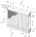
図1、図2に示すように、本実施形態の冷媒蒸発器1は、送風空気の流れ方向(被冷却流体の流れ方向)Xに対して直列に配置された2つの蒸発部10、20を備えて構成されている。ここで、本実施形態では、2つの蒸発部10、20のうち、送風空気の流れ方向の風下側(下流側)に配置される蒸発部を風下側蒸発部10と称し、送風空気の流れ方向の風上側(上流側)に配置される蒸発部を風上側蒸発部20と称する。なお、本実施形態における風下側蒸発部10が、特許請求の範囲の「第1蒸発部」を構成し、風上側蒸発部20が、特許請求の範囲の「第2蒸発部」を構成している。
As shown in FIGS. 1 and 2, the
風下側蒸発部10および風上側蒸発部20の基本的構成は同一であり、それぞれコア部11、21と、コア部11、21の上下両側に配置された一対のタンク部12、13、22、23を有して構成されている。
The basic configurations of the leeward
なお、本実施形態では、風下側蒸発部10におけるコア部を風下側コア部11と称し、風上側蒸発部20におけるコア部を風上側コア部21と称する。また、風下側蒸発部10における一対のタンク部12、13のうち、上方側に配置されるタンク部を第1風下側タンク部12と称し、下方側に配置されるタンク部を第2風下側タンク部13と称する。同様に、風上側蒸発部20における一対のタンク部22、23のうち、上方側に配置されるタンク部を第1風上側タンク部22と称し、下方側に配置されるタンク部を第2風上側タンク部23と称する。
In the present embodiment, the core part in the
本実施形態の風下側コア部11および風上側コア部21それぞれは、上下方向(鉛直方向)に延びる複数のチューブ111、211と、隣り合うチューブ111、211の間に接合されるフィン112とが交互に積層配置された積層体で構成されている。なお、以下、複数のチューブ111、211および複数のフィン112の積層体における積層方向をチューブ積層方向と称する。また、図1および図2では、図示の明確化のため、フィン112を一部のみ図示しているが、フィン112は、隣り合うチューブ111の間の略全域に渡って配置されている。また、図1および図2では、図示の明確化のため、風上側蒸発部20のフィンの図示を省略しているが、風上側蒸発部20においても、風下側蒸発部10と同様に、隣り合チューブ211の間の略全域に渡ってフィンが配置されている。
Each of the
ここで、風下側コア部11は、複数のチューブ111のうち、一部のチューブ群で構成される第1風下側コア部11a、および残部のチューブ群で構成される第2風下側コア部11bを有している。なお、本実施形態における第1風下側コア部11aが、特許請求の範囲における「第1コア部」を構成し、第2風下側コア部11bが、特許請求の範囲における「第2コア部」を構成する。
Here, the leeward
本実施形態では、風下側コア部11を送風空気流れ下流側から(図1、図2、図5における矢印Y方向から)見たときに、チューブ積層方向の左側に存するチューブ群で第1風下側コア部11aが構成され、チューブ積層方向の右側に存するチューブ群で第2風下側コア部11bが構成されている。
In this embodiment, when the leeward
また、風上側コア部21は、複数のチューブ211のうち、一部のチューブ群で構成される第1風上側コア部21a、および残部のチューブ群で構成される第2風上側コア部21bを有している。なお、本実施形態における第1風上側コア部21aが、特許請求の範囲における「第3コア部」を構成し、第2風上側コア部21bが、特許請求の範囲における「第4コア部」を構成する。
Further, the
本実施形態では、風上側コア部21を送風空気流れ下流側から見たときに、チューブ積層方向の左側に存するチューブ群で第1風上側コア部21aが構成され、チューブ積層方向の右側に存するチューブ群で第2風上側コア部21bが構成されている。なお、本実施形態では、送風空気の流れ方向から見たときに、第1風下側コア部11aおよび第1風上側コア部21aそれぞれが重合(対向)するように配置されると共に、第2風下側コア部11bおよび第2風上側コア部21bそれぞれが重合(対向)するように配置されている。
In the present embodiment, when the
各チューブ111、211は、内部に冷媒が流れる冷媒通路が形成されると共に、その断面形状が送風空気の流れ方向に沿って延びる扁平形状となる扁平チューブで構成されている。
Each of the
風下側コア部11のチューブ111は、長手方向の一端側(上端側)が第1風下側タンク部12に接続されると共に、長手方向の他端側(下端側)が第2風下側タンク部13に接続されている。また、風上側コア部21のチューブ211は、長手方向の一端側(上端側)が第1風上側タンク部22に接続されると共に、長手方向の他端側(下端側)が第2風上側タンク部23に接続されている。
The
各フィン112は、薄板材を波状に曲げて成形したコルゲートフィンであり、チューブ111、211における平坦な外面側に接合され、送風空気と冷媒との伝熱面積を拡大させるための熱交換促進手段を構成する。
Each
チューブ111、211およびフィン112の積層体には、チューブ積層方向の両端部に、各コア部11、12を補強するサイドプレート113、213が配置されている。なお、サイドプレート113、213は、チューブ積層方向の最も外側に配置されたフィン112に接合されている。
In the laminated body of the
第1風下側タンク部12は、一端側(送風空気流れ下流側から見たときの右側端部)が閉塞されると共に、他端側(送風空気流れ下流側から見たときの左側端部)に膨張弁(図示略)にて減圧された低圧冷媒を導入するための冷媒導入部12aが接続された筒状の部材で構成されている。この第1風下側タンク部12は、底部に各チューブ111の一端側(上端側)が挿入接合される貫通穴(図示略)が形成されている。つまり、第1風下側タンク部12は、その内部空間が風下側コア部11の各チューブ111に連通するように構成されており、風下側コア部11の各コア部11a、11bへ冷媒を分配する冷媒分配部として機能する。
The first
第1風上側タンク部22は、一端側が閉塞されると共に、他端側にタンク内部にタンク内部から圧縮機(図示略)の吸入側に冷媒を導出するための冷媒導出部22aが形成された筒状の部材で構成されている。この第1風上側タンク部22は、底部に各チューブ211の一端側(上端側)が挿入接合される貫通穴(図示略)が形成されている。つまり、第1風上側タンク部22は、その内部空間が風上側コア部21の各チューブ211に連通するように構成されており、風上側コア部21の各コア部21a、21bからの冷媒を集合させる冷媒集合部として機能する。
The first
第2風下側タンク部13は、両端側が閉塞された筒状の部材で構成されている。この第2風下側タンク部13は、天井部に各チューブ111の他端側(下端側)が挿入接合される貫通穴(図示略)が形成されている。つまり、第2風下側タンク部13は、その内部空間が各チューブ111に連通するように構成されている。
The 2nd leeward
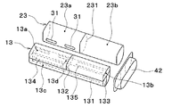
図3および図4に示すように、第2風下側タンク部13の内部には、上下方向の中央位置に第1仕切部131が配置されており、この第1仕切部131によって、タンク内部空間が上側空間と下側空間とに仕切られている。また、上側空間の内部には、長手方向(チューブ積層方向)の中央位置に第2仕切部132が配置されており、この第2仕切部132によって、上側空間が第1風下側コア部11aを構成する各チューブ111が連通する空間と、第2風下側コア部11bを構成する各チューブ111が連通する空間とに仕切られている。
As shown in FIGS. 3 and 4, a
ここで、第2風下側タンク部13の上側空間の内部のうち、第1風下側コア部11aを構成する各チューブ111に連通する空間が、第1風下側コア部11aからの冷媒を集合させる第1冷媒集合部13aを構成し、第2風下側コア部11bを構成する各チューブ111に連通する空間が、第2風下側コア部11bからの冷媒を集合させる第2冷媒集合部13bを構成する。
Here, in the inside of the upper space of the second
第2風下側タンク部13の下側空間の内部には、当該下側空間の一部を、送風空気の流れ方向(前後方向)に2つに仕切る第3仕切部133が配置されている。この第3仕切部133は、第1部材133aおよび第2部材133bの2つの部材を有して構成されている。
Inside the lower space of the second
第1部材133aは、長手方向の一端側において、第2風下側タンク部13のチューブ積層方向における冷媒導入部12aに近い側(紙面左側)の端部に接続されるとともに、下側空間の一部を送風空気の流れ方向に2つに仕切るように形成されている。第1部材133aは、下側空間における送風空気の流れ方向の中央位置に配置されている。
The
第2部材133bは、第1部材133bにおける長手方向の他端側の端部に接続されるとともに、第2風上側タンク部23側(送風空気流れ上流側)に向かって延びている。
The
このように構成された第3仕切部133によって、第2風下側タンク部13の下側空間が、チューブ111の長手方向(以下、チューブ長手方向(紙面矢印Z方向)と称する)から見たときに略L字状に形成されている第1下側空間13cと、チューブ積層方向に延びる第2下側空間13dとに仕切られている。
When the lower space of the second
第1仕切部131には、第1冷媒集合部13aと第1下側空間13cとを連通させる第1連通穴134、および第2冷媒集合部13bと第2下側空間13dとを連通させる第2連通穴135が形成されている。より詳細には、第1連通穴134は、第1仕切部131における送風空気流れ下流側、かつ、チューブ積層方向における冷媒導入部12aに近い側に配置されている。また、第2連通穴135は、第1仕切部131における送風空気流れ上流側、かつ、チューブ積層方向における中央部よりもやや冷媒導入部12aから遠い部位に配置されている。
The
第2風上側タンク部23は、両端側が閉塞された筒状の部材で構成されている。この第2風上側タンク部23は、天井部に各チューブ211の他端側(下端側)が挿入接合される貫通穴(図示略)が形成されている。つまり、第2風上側タンク部23は、その内部空間が各チューブ211に連通するように構成されている。
The second
第2風上側タンク部23の内部には、長手方向の中央位置に仕切部231が配置されており、この仕切部231によって、タンク内部空間が第1風上側コア部21aを構成する各チューブ211が連通する空間と、第2風上側コア部21bを構成する各チューブ211が連通する空間とに仕切られている。
Inside the second
ここで、第2風上側タンク部23の内部のうち、第1風上側コア部21aを構成する各チューブ211に連通する空間が、第1風上側コア部21aに冷媒を分配する第1冷媒分配部23aを構成し、第2風上側コア部21bを構成する各チューブ211が連通する空間が、第2風上側コア部21bに冷媒を分配する第2冷媒分配部23bを構成する。
Here, in the inside of the second windward
第2風下側タンク部13の第2下側空間13dと第2風上側タンク部23の第1冷媒分配部23aとは、第1連通部31を介して接続されている。また、第2風下側タンク部13の第1下側空間13cと第2風上側タンク部23の第2冷媒分配部23bとは、第2連通部32を介して接続されている。
The second
本実施形態では、第1連通部31は、チューブ積層方向に延びており、第2風下側タンク部13および第2風上側タンク部23のチューブ積層方向における冷媒導入部12aに近い側の領域に2つ配置されている。また、第2連通部32は、チューブ積層方向に延びており、第2風下側タンク部13および第2風上側タンク部23のチューブ積層方向における冷媒導入部12aから遠い側の端部近傍に1つ配置されている。
In this embodiment, the
ここで、第2風下側タンク部13および第2風上側タンク部23における冷媒流れについて説明する。図4の一点鎖線矢印に示すように、第1風下側コア部11aを構成する各チューブ111から流出した冷媒は、第2風下側タンク部13の第1冷媒集合部13aに集合した後、第1連通穴134を介して第1下側空間13cに流入する。第1下側空間13cに流入した冷媒は、第1下側空間13cを、チューブ積層方向における冷媒導入部12aに近い側から遠い側に向かって流れて、第2連通部32を介して第2風上側タンク部23の第2冷媒分配部23bに流入する。第2冷媒分配部23bに流入した冷媒は、第2風上側コア部21bを構成する各チューブ211に分配される。
Here, the refrigerant flow in the second
一方、図4の破線矢印に示すように、第2風下側コア部11bを構成する各チューブ111から流出した冷媒は、第2風下側タンク部13の第2冷媒集合部13bに集合した後、第2連通穴135を介して第2下側空間13dに流入する。第2下側空間13dに流入した冷媒は、第2下側空間13dを、チューブ積層方向における冷媒導入部12aに遠い側から近い側に向かって流れて、第1連通部31を介して第2風上側タンク部23の第1冷媒分配部23aに流入する。第1冷媒分配部23bに流入した冷媒は、第1風上側コア部21aを構成する各チューブ211に分配される。
On the other hand, as shown by the broken line arrows in FIG. 4, after the refrigerant flowing out from each
したがって、冷媒が第2風下側タンク部13の下側空間13c、13dを流通する際に、冷媒の流れが各コア部11、21においてチューブ積層方向(コア部11、12の幅方向)に入れ替えられる。このため、本実施形態における第2風下側タンク部13の下側空間13c、13dが、特許請求の範囲の「冷媒入替部」を構成している。
Therefore, when the refrigerant flows through the
また、第2風下側タンク部13の第1下側空間13cでは、冷媒がチューブ積層方向における冷媒導入部12aに近い側から遠い側に向かって流れており、第2風下側タンク部13の第2下側空間13dでは、冷媒がチューブ積層方向における冷媒導入部12aに遠い側から近い側に向かって流れている。つまり、第1下側空間13c内の冷媒流れと、第2下側空間13d内の冷媒流れとが、対向流になっている。
Further, in the first
したがって、冷媒入替部、つまり第2風下側タンク部13の下側空間13c、13dにおいて、第1冷媒集合部13aからの冷媒を第2冷媒分配部23bへ導く冷媒流れ、および、第2冷媒集合部13bからの冷媒を第1冷媒分配部23aへ導く冷媒流れが、チューブ長手方向から見たときに非交差状態となっている。
Therefore, in the refrigerant replacement part, that is, in the
本実施形態では、第1風下側タンク部12および第1風上側タンク部22は、一体に形成されており、第2風下側タンク部13および第1風上側タンク部23は、一体に形成されている。以下、第1風下側タンク部12と第1風上側タンク部22が一体化されたものを、第1ヘッダタンク51といい、第2風下側タンク部13と第2風上側タンク部23が一体化されたものを、第2ヘッダタンク52という。
In the present embodiment, the first
各ヘッダタンク51、52は、送風空気の流れ方向に2列に配置されたチューブ111、211双方が固定されるヘッダプレート511、521、およびタンク形成部材512、522を有している。タンク形成部材512、522は、ヘッダプレート511、521に固定されることによって、その内部に冷媒が流通する空間を形成するものである。具体的には、タンク形成部材512、521は、平板金属にプレス加工を施すことにより、その長手方向から見たときに、二山状(W字状)に形成されている。
Each of the
そして、タンク形成部材512の二山状の中央部がヘッダプレート511に接合されることによって、第1風下側タンク部12および第1風上側タンク部22が区画されている。また、タンク形成部材522の二山状の中央部がヘッダプレート521に接合されることによって、第2風下側タンク部13および第2風上側タンク部23が区画されている。また、タンク形成部材522の二山状の中央部とヘッダプレート521との間に一部隙間を形成することにより、第1連通部31および第2連通部32が構成されている。
And the 1st leeward
以上説明したように、第2風下側タンク部13の下側空間13c、13dは、第1冷媒集合部13aの冷媒を第2冷媒分配部23bに導くとともに、第2冷媒集合部13bの冷媒を第1冷媒分配部23aに導くように構成されるため、第2風下側タンク部13内において、冷媒の流れ方向をコア部11、21の幅方向(チューブ積層方向)で入れ替えることができる。このとき、冷媒の流れ方向を入れ替えるために、第2風下側タンク部13以外の別の部材を設ける必要がない。したがって、冷媒封入量の増加を抑制しつつ、冷媒の流れ方向をコア部11、21の幅方向で入れ替えることが可能となる。
As described above, the
さらに、本実施形態では、冷媒入替部、つまり第2風下側タンク部13の下側空間13c、13dは、第1冷媒集合部13aからの冷媒を第2冷媒分配部23bへ導く冷媒流れ、および、第2冷媒集合部13bからの冷媒を第1冷媒分配部23aへ導く冷媒流れが、チューブ長手方向から見たときに非交差状態となるように構成される。これにより、上記従来技術のように交差連通部を隣り合うチューブ111、211間に配置する必要がないので、冷媒の流れ方向をコア部11、21の幅方向で入れ替える際に生じる冷媒の圧力損失が大きくなることを抑制できる。このため、冷媒蒸発器1における送風空気の冷却性能を向上させることが可能となる。
Furthermore, in the present embodiment, the refrigerant replacement part, that is, the
ここで、比較例に係る冷媒蒸発器を図5に示す。比較例に係る冷媒蒸発器1は、上述した特許文献1に記載されている、風下側コア部11を通過した後の冷媒を、風上側コア部に流入させる前に左右で(コア部の幅方向で、または、チューブ積層方向で)交差させるための交差連通部30Jを、第2風下側タンク部13の左右方向中央部に設けたものである。なお、図5における一点鎖線矢印および破線矢印は、冷媒の流れを示している。
Here, the refrigerant evaporator which concerns on a comparative example is shown in FIG. The
そして、比較例に係る冷媒蒸発器1の各コア部11、21を流れる液相冷媒の分布を図6に示し、第1実施形態に係る冷媒蒸発器1の各コア部11、21を流れる液相冷媒の分布を図7に示す。図6(a)および図7(a)は、風下側コア部11を流れる液相冷媒の分布を示し、図6(b)および図7(b)は、風上側コア部21を流れる液相冷媒の分布を示し、図6(c)および図7(c)は、各コア部11、21を流れる液相冷媒の分布の合成を示している。なお、図6および図7は、冷媒蒸発器1を図1の矢印Y方向(送風空気の流れ方向Xの逆方向)から見たときの液相冷媒の分布を示すもので、図中の網掛部分で示す箇所が、液相冷媒が存する部分を示す。
And distribution of the liquid-phase refrigerant | coolant which flows through each
まず、風下側コア部11を流れる液相冷媒の分布については、図6(a)および図7(a)で示すように、比較例に係る冷媒蒸発器1と本実施形態に係る冷媒蒸発器1とで同様であり、第2風下側コア部11bにおける冷媒導入部12aから遠い側に、液相冷媒が流れ難い箇所(図中右下方側の白抜き箇所)が生ずる。
First, with respect to the distribution of the liquid-phase refrigerant flowing through the
一方、比較例に係る冷媒蒸発器1における風上側コア部21を流れる液相冷媒の分布については、図6(b)に示すように、風上側コア部21の各コア部21a、21bでは、チューブ積層方向において、交差連通部30Jが形成された部位(中央部)に液相冷媒が流れ易く、交差連通部30Jが形成されていない部位(両端部)に液相冷媒が流れ難くなっている。
On the other hand, regarding the distribution of the liquid-phase refrigerant flowing through the
そして、図6(c)に示すように、比較例に係る冷媒蒸発器1を送風空気の流れ方向Xから見たときに、第2風下側コア部11bおよび第2風上側コア部21bにおける重合する部位の一部、つまりチューブ積層方向における冷媒導入部12aから遠い側の端部近傍に、液相冷媒が流れ難い箇所(図中右側の白抜き箇所)が生ずる。
Then, as shown in FIG. 6C, when the
このように液相冷媒が分布する比較例に係る冷媒蒸発器1では、液相冷媒が流れ難い箇所にて冷媒の顕熱分の熱量を送風空気から吸熱するだけなので、送風空気を充分に冷却することができない。この結果、冷媒蒸発器1を通過する送風空気に温度分布が生じてしまうこととなる。
Thus, in the
これに対して、本実施形態に係る冷媒蒸発器1における風上側コア部21を流れる液相冷媒の分布については、第2連通部32を、第2風上側タンク部23のチューブ積層方向における冷媒導入部12aから遠い側の端部に接続しているので、図7(b)に示すように、風上側コア部21では、チューブ積層方向における冷媒導入部12aから遠い側の端部近傍に液相冷媒が流れ易くなっている。
On the other hand, regarding the distribution of the liquid phase refrigerant flowing through the
そして、図7(c)に示すように、本実施形態に係る冷媒蒸発器1を送風空気の流れ方向Xから見たときに、第2風下側コア部11bおよび第2風上側コア部21bにおける重合する部位の全域に液相冷媒が流れる。このように液相冷媒が分布する本実施形態に係る冷媒蒸発器1では、各コア部11、21のいずれかによって、冷媒の蒸発潜熱分の熱量を送風空気から吸熱するので、送風空気を充分に冷却することが可能となる。この結果、冷媒蒸発器1を通過する送風空気に温度分布が生じてしまうことが抑制される。
7C, when the
すなわち、風上側コア部21における液相冷媒が流れやすい箇所を、風下側コア部11における液相冷媒が流れ難い箇所と対向するように、つまり送風空気の流れ方向Xから見たときに重合するように配置することで、冷媒蒸発器1全体として、冷媒蒸発器1を通過する送風空気に温度分布が生じることを抑制できる。
That is, the portion where the liquid phase refrigerant easily flows in the
(第2実施形態)
次に、本発明の第2実施形態について図8〜図11に基づいて説明する。本第2実施形態は、上記第1実施形態と比較して、第2風下側タンク部13の第1下側空間13cと第2風上側タンク部23の第2冷媒分配部23bとの連通部分の構成等が異なるものである。
(Second Embodiment)
Next, 2nd Embodiment of this invention is described based on FIGS. Compared with the first embodiment, the second embodiment is a communication portion between the first
本実施形態の第3仕切部133は、長手方向(チューブ積層方向)の両端部において、第2風下側タンク部13の内壁面に接続されている。このように構成された第3仕切部133によって、第2風下側タンク部13の下側空間の全域が、送風空気の流れ方向に、第1下側空間13cおよび第2下側空間13dの2つに仕切られている。第1下側空間13cは、第2下側空間13dに対して、送風空気流れ下流側に配置されている。なお、第3仕切部133は、下側空間における送風空気の流れ方向の中央位置に配置されている。
The
第2風下側タンク部13と第2風上側タンク部23とは、ジョイント42によって連結されている。ジョイント42は、第2風下側タンク部13および第2風上側タンク部23それぞれの、チューブ積層方向における冷媒導入部12aから遠い側の端部に接続されている。
The second
ジョイント42の内部には、冷媒が流通する冷媒流路が形成されている。第2風下側タンク部13の第1下側空間13cと第2風上側タンク部23の第2冷媒分配部23bとは、ジョイント42内部の冷媒流路を介して接続されている。このため、本実施形態におけるジョイント42が、特許請求の範囲の「第2連通部」を構成している。
Inside the joint 42, a refrigerant channel through which the refrigerant flows is formed. The first
ここで、第2風下側タンク部13および第2風上側タンク部23における冷媒流れについて、上記第1実施形態と異なる部分のみ説明する。図11の一点鎖線矢印に示すように、第1風下側コア部11aを構成する各チューブ111から流出した冷媒は、第2風下側タンク部13の第1冷媒集合部13aに集合した後、第1連通穴134を介して第1下側空間13cに流入する。第1下側空間13cに流入した冷媒は、第1下側空間13cを、チューブ積層方向における冷媒導入部12aに近い側から遠い側に向かって流れて、ジョイント42内の冷媒流路を介して第2風上側タンク部23の第2冷媒分配部23bに流入する。第2冷媒分配部23bに流入した冷媒は、第2風上側コア部21bを構成する各チューブ211に分配される。
Here, only the parts different from the first embodiment will be described regarding the refrigerant flow in the second
以上説明した本第2実施形態の構成によっても、上記第1実施形態と同様の効果を得ることができる。 Even with the configuration of the second embodiment described above, the same effect as that of the first embodiment can be obtained.
(第3実施形態)
次に、本発明の第3実施形態について図12〜図15に基づいて説明する。本第3実施形態は、上記第2実施形態と比較して、第2風下側タンク部13の第2下側空間13dと第2風上側タンク部23の第1冷媒分配部23aとの連通部分の構成等が異なるものである。
(Third embodiment)
Next, a third embodiment of the present invention will be described with reference to FIGS. Compared with the second embodiment, the third embodiment is a communication portion between the second
本実施形態の第2風下側タンク部13と第2風上側タンク部23とは、第1ジョイント41および第2ジョイント42によって連結されている。第1ジョイント41は、第2風下側タンク部13および第2風上側タンク部23それぞれの、チューブ積層方向における冷媒導入部12aに近い側の端部に接続されている。第2ジョイント42は、第2風下側タンク部13および第2風上側タンク部23それぞれの、チューブ積層方向における冷媒導入部12aから遠い側の端部に接続されている。
The second
第1ジョイント41および第2ジョイント42の内部には、それぞれ、冷媒が流通する冷媒流路が形成されている。第2風下側タンク部13の第2下側空間13dと第2風上側タンク部23の第1冷媒分配部23aとは、第1ジョイント41内部の冷媒流路を介して接続されている。第2風下側タンク部13の第1下側空間13cと第2風上側タンク部23の第2冷媒分配部23bとは、第2ジョイント42内部の冷媒流路を介して接続されている。このため、本実施形態における第1ジョイント41が、特許請求の範囲の「第1連通部」を構成し、本実施形態における第2ジョイント42が、特許請求の範囲の「第2連通部」を構成している。
Inside the first joint 41 and the second joint 42, refrigerant flow paths through which the refrigerant flows are formed. The second
ここで、第2風下側タンク部13および第2風上側タンク部23における冷媒流れについて、上記第2実施形態と異なる部分のみ説明する。図15の破線矢印に示すように、第2風下側コア部11bを構成する各チューブ111から流出した冷媒は、第2風下側タンク部13の第2冷媒集合部13bに集合した後、第2連通穴135を介して第2下側空間13dに流入する。第2下側空間13dに流入した冷媒は、第2下側空間13dを、チューブ積層方向における冷媒導入部12aに遠い側から近い側に向かって流れて、第1ジョイント41内の冷媒流路を介して第2風上側タンク部23の第1冷媒分配部23aに流入する。第1冷媒分配部23aに流入した冷媒は、第1風上側コア部21aを構成する各チューブ211に分配される。
Here, only the parts different from the second embodiment will be described regarding the refrigerant flow in the second
以上説明した本第3実施形態の構成によっても、上記第2実施形態と同様の効果を得ることができる。 Even with the configuration of the third embodiment described above, the same effects as those of the second embodiment can be obtained.
(第4実施形態)
次に、本発明の第4実施形態について図16〜図18に基づいて説明する。本第4実施形態は、上記第1実施形態と比較して、第2風下側タンク部13および第2風上側タンク部23の構成等が異なるものである。
(Fourth embodiment)
Next, a fourth embodiment of the present invention will be described with reference to FIGS. The fourth embodiment is different from the first embodiment in the configuration of the second
図16および図17に示すように、第2風下側タンク部13の内部には、チューブ積層方向の略中央位置に、タンク内部空間を、チューブ積層方向に第1空間130Aおよび第2空間130Bの2つに仕切る第2仕切部132が配置されている。第1空間130Aは第1風下側コア部11aと対応する部位(紙面左側)に配置されており、第2空間130Bは第2風下側コア部11bと対応する部位(紙面右側)に配置されている。
As shown in FIGS. 16 and 17, the second
第2空間130Bには、上下方向の略中央位置に第1仕切部131が配置されており、この第1仕切部131によって、第2空間130Bが上側空間と下側空間とに仕切られている。
In the
第1仕切部131および第2仕切部132によって仕切られたタンク内部空間のうち、第1空間130Aが第1風下側コア部11aを構成する各チューブ111が連通する空間を構成しており、第2空間130Bの上側空間が第2風下側コア部11bを構成する各チューブ111が連通する空間を構成している。
Of the tank internal space partitioned by the
ここで、第2風下側タンク部13のタンク内部空間のうち、第1風下側コア部11aを構成する各チューブ111に連通する空間(つまり、第1空間130A)が、第1風下側コア部11aからの冷媒を集合させる第1冷媒集合部13aを構成し、第2風下側コア部11bを構成する各チューブ111に連通する空間(つまり、第2空間130Bの上側空間)が、第2風下側コア部11bからの冷媒を集合させる第2冷媒集合部13bを構成する。
Here, of the tank internal space of the second
第2風下側タンク部13における第2空間130Bの下側空間の内部には、当該下側空間の一部を、送風空気の流れ方向(前後方向)に2つに仕切る第3仕切部133が配置されている。この第3仕切部133は、第1部材133aおよび第2部材133bの2つの部材を有して構成されている。
Inside the lower space of the second space 130 </ b> B in the second
第1部材133aは、長手方向の一端側にいて、第2仕切部132に接続されるとともに、下側空間の一部を送風空気の流れ方向に2つに仕切るように形成されている。第1部材133aは、下側空間における送風空気の流れ方向の中央位置に配置されている。
The
第2部材133bは、第1部材133bにおける長手方向の他端側の端部に接続されるとともに、第2風上側タンク部23側(送風空気流れ上流側)に向かって延びている。
The
このように構成された第3仕切部133によって、第2風下側タンク部13の第2空間130Bの下側空間が、チューブ長手方向Zから見たときに略L字状に形成されている第1下側空間13cと、チューブ積層方向に延びる第2下側空間13dとに仕切られている。
With the
第2仕切部132には、第1冷媒集合部13aと第1下側空間13cとを連通させる第1連通穴134が形成されている。また、第1仕切部131には、第2冷媒集合部13bと第2下側空間13dとを連通させる第2連通穴135が形成されている。より詳細には、第1連通穴134は、第2仕切部132における送風空気流れ下流側、かつ、下方側に配置されている。また、第2連通穴135は、第1仕切部131における送風空気流れ上流側、かつ、チューブ積層方向における中央部よりもやや冷媒導入部12aから遠い部位に配置されている。
The
ところで、本実施形態では、第2風上側タンク部23の内部に仕切部231が配置されていない。このため、第2風上側タンク部23の内部は、第1風上側コア部21aおよび第2風上側コア部21bの双方に冷媒を分配する冷媒分配部23cを構成している。
By the way, in this embodiment, the
第2風上側タンク部23には、第2冷媒集合部13bから第2風上側タンク部23内に冷媒を流入させる第1連通部31と、第1冷媒集合部13aから第2風上側タンク部23内に冷媒を流入させる第2連通部32とが接続されている。第1連通部31および第2連通部32は、それぞれ、第2風上側タンク部23における第2風上側コア部21bに属するチューブ211と対応する部位(紙面右側)に配置されている。第1連通部31は、第2連通部32よりも、チューブ積層方向における第1風上側コア部21aに近い側(冷媒導入部12aに近い側)に配置されている。
The second
ここで、第2風下側タンク部13および第2風上側タンク部23における冷媒流れについて説明する。図17の一点鎖線矢印に示すように、第1風下側コア部11aを構成する各チューブ111から流出した冷媒は、第2風下側タンク部13の第1冷媒集合部13aに集合した後、第1連通穴134を介して第1下側空間13cに流入する。第1下側空間13cに流入した冷媒は、第1下側空間13cを、チューブ積層方向における冷媒導入部12aに近い側から遠い側に向かって流れて、第2連通部32を介して第2風上側タンク部23における冷媒導入部12aから遠い側に流入し、風上側蒸発部20の各チューブ211に分配される。
Here, the refrigerant flow in the second
一方、図17の破線矢印に示すように、第2風下側コア部11bを構成する各チューブ111から流出した冷媒は、第2風下側タンク部13の第2冷媒集合部13bに集合した後、第2連通穴135を介して第2下側空間13dに流入する。第2下側空間13dに流入した冷媒は、第1連通部31を介して第2風上側タンク部23における冷媒導入部12aから遠い側に流入し、風上側蒸発部20の各チューブ211に分配される。
On the other hand, as shown by the broken line arrows in FIG. 17, after the refrigerant flowing out from each
したがって、冷媒が第2風下側タンク部13の下側空間13c、13dを流通する際に、冷媒の流れが各コア部11、21においてチューブ積層方向(コア部11、12の幅方向)に入れ替えられる。このため、本実施形態における第2風下側タンク部13の下側空間13c、13dが、特許請求の範囲の「冷媒入替部」を構成している。
Therefore, when the refrigerant flows through the
そして、冷媒入替部、つまり第2風下側タンク部13の下側空間13c、13dにおいて、第1冷媒集合部13aからの冷媒を第2連通部32を介して冷媒分配部23c(第2風上側タンク部23)へ導く冷媒流れ、および、第2冷媒集合部13bからの冷媒を第1連通部31を介して冷媒分配部23cへ導く冷媒流れが、チューブ長手方向から見たときに非交差状態となっている。
Then, in the refrigerant replacement part, that is, the
以上説明したように、第2風下側タンク部13の下側空間13c、13dは、第1冷媒集合部13aからの冷媒を第2連通部32を介して冷媒分配部23cへ導くとともに、第2冷媒集合部13bからの冷媒を第1連通部31を介して冷媒分配部23cへ導くように構成されるため、第2風下側タンク部13内において、冷媒の流れ方向をコア部11、21の幅方向(チューブ積層方向)で入れ替えることができる。このとき、冷媒の流れ方向を入れ替えるために、第2風下側タンク部13以外の別の部材を設ける必要がないので、上記第1実施形態と同様に、冷媒封入量の増加を抑制しつつ、冷媒の流れ方向をコア部11、21の幅方向で入れ替えることが可能となる。
As described above, the
さらに、本実施形態では、冷媒入替部、つまり第2風下側タンク部13の下側空間13c、13dは、第1冷媒集合部13aからの冷媒を第2連通部32を介して冷媒分配部23cへ導く冷媒流れ、および、第2冷媒集合部13bからの冷媒を第1連通部31を介して冷媒分配部23cへ導く冷媒流れが、チューブ長手方向から見たときに非交差状態となるように構成される。これにより、上記第1実施形態と同様に、冷媒蒸発器1における送風空気の冷却性能を向上させることが可能となる。
Furthermore, in the present embodiment, the refrigerant replacement unit, that is, the
さらに、本実施形態では、第2風下側タンク部13の第1空間130Aを上下に仕切る必要がなく、また第2風上側タンク部23内部の仕切部231を廃止することができるので、より簡素な構成で、かつ、部品点数を削減しつつ、上記第1実施形態と同様の効果を得ることができる。
Furthermore, in this embodiment, it is not necessary to partition the
ここで、本実施形態に係る冷媒蒸発器1における液相冷媒の分布について、図18に基づいて説明する。なお、図18は、第1実施形態の図7に対応する図面である。
Here, the distribution of the liquid-phase refrigerant in the
まず、風下側コア部11を流れる液相冷媒の分布については、図18(a)で示すように、第2風下側コア部11bにおける冷媒導入部12aから遠い側に、液相冷媒が流れ難い箇所(図中右下方側の白抜き箇所)が生ずる。
First, as for the distribution of the liquid-phase refrigerant flowing through the
風上側コア部21を流れる液相冷媒の分布については、第1連通部31および第2連通部32の双方を、第2風上側タンク部23のチューブ積層方向における冷媒導入部12aから遠い側に接続しているので、図18(b)に示すように、風上側コア部21では、チューブ積層方向における冷媒導入部12aから遠い側に液相冷媒が流れ易くなっている。
Regarding the distribution of the liquid-phase refrigerant flowing through the windward
そして、図18(c)に示すように、本実施形態に係る冷媒蒸発器1を送風空気の流れ方向Xから見たときに、第2風下側コア部11bおよび第2風上側コア部21bにおける重合する部位の全域に液相冷媒が流れる。このように液相冷媒が分布する本実施形態に係る冷媒蒸発器1では、各コア部11、21のいずれかによって、冷媒の蒸発潜熱分の熱量を送風空気から吸熱するので、送風空気を充分に冷却することが可能となる。この結果、冷媒蒸発器1を通過する送風空気に温度分布が生じてしまうことが抑制される。
As shown in FIG. 18C, when the
(他の実施形態)
本発明は上述の実施形態に限定されることなく、本発明の趣旨を逸脱しない範囲内で、以下のように種々変形可能である。
(Other embodiments)
The present invention is not limited to the above-described embodiment, and can be variously modified as follows without departing from the spirit of the present invention.
(1)上記各実施形態では、第2風下側タンク部13の内部に冷媒入替部を設けた例について説明したが、これに限らず、第2風上側タンク部23の内部に設けてもよいし、第2風下側タンク部13および第2風上側タンク部23の双方に設けてもよい。
(1) In each of the above embodiments, the example in which the refrigerant replacement unit is provided inside the second
(2)上記各実施形態では、第1風下側タンク部12および第1風上側タンク部22を一体に形成するとともに、第2風下側タンク部13および第1風上側タンク部23を一体に形成した例について説明したが、これに限らず、第1風下側タンク部12および第1風上側タンク部22を別体として構成するとともに、第2風下側タンク部13および第1風上側タンク部23を別体として構成してもよい。
(2) In the above embodiments, the first
10、20 蒸発部
11、22 コア部
12、13、22、23 タンク部
12a 冷媒導入部
13a、13b 冷媒集合部
13c、13d 下側空間(冷媒入替部)
23a、23b 冷媒分配部
31、32 連通部
111、211 チューブ
10, 20 Evaporating
23a, 23b
Claims (3)
前記被冷却流体の流れ方向に対して直列に配置された第1蒸発部(10)、および第2蒸発部(20)を備え、
前記第1蒸発部(10)および前記第2蒸発部(20)それぞれは、
前記冷媒が流れる複数のチューブ(111、211)を積層して構成されるコア部(11、21)と、
前記複数のチューブ(111、211)の両端部に接続され、前記複数のチューブ(111、211)を流れる前記冷媒の集合あるいは分配を行う一対のタンク部(12、13、22、23)とを有し、
前記第1蒸発部(10)における前記コア部(11)は、前記複数のチューブ(111)のうち、一部のチューブ群で構成される第1コア部(11a)、および残部のチューブ群で構成される第2コア部(11b)を有し、
前記第2蒸発部(20)における前記コア部(21)は、前記複数のチューブ(211)のうち、前記被冷却流体の流れ方向において前記第1コア部 (11a)の少なくとも一部と対向するチューブ群で構成される第3コア部(21a)、および前記被冷却流体の流れ方向において前記第2コア部(11b)の少なくとも一部と対向するチューブ群で構成される第4コア部(21b)を有し、
前記第1蒸発部(10)における前記一対のタンク部(12、13)のうち、一方のタンク部(13)は、前記第1コア部(11a)からの冷媒を集合させる第1冷媒集合部(13a)、および前記第2コア部(11b)からの冷媒を集合させる第2冷媒集合部(13b)を含んで構成され、
前記第2蒸発部(20)における前記一対のタンク部(22、23)のうち、一方のタンク部(23)は、前記第3コア部(21a)に冷媒を分配させる第1冷媒分配部(23a)、および前記第4コア部(21b)に冷媒を分配させる第2冷媒分配部(23b)を含んで構成され、
前記第2冷媒集合部(13b)と前記第1冷媒分配部(23a)とは、第1連通部(31)を介して接続されており、
前記第1冷媒集合部(13a)と前記第2冷媒分配部(23b)とは、第2連通部(32)を介して接続されており、
前記第1蒸発部(10)の前記一方のタンク部(13)および前記第2蒸発部(20)の前記一方のタンク部(23)のうち、少なくとも一方のタンク部 (13)の内部には、前記第1冷媒集合部(13a)の冷媒を前記第2冷媒分配部(23b)に導くとともに、前記第2冷媒集合部(13b)の冷媒を前記第1 冷媒分配部(23a)に導く冷媒入替部(13c、13d)が設けられており、
前記冷媒入替部(13c、13d)は、前記第1冷媒集合部(13a)からの前記冷媒を前記第2冷媒分配部(23b)へ導く冷媒流れ、および、前記第2冷媒集合部(13b)からの前記冷媒を前記第1冷媒分配部(23a)へ導く冷媒流れが、前記チューブ(111、222)の長手方向から見たときに非交差状態となるように構成されており、
前記第1蒸発部(10)の前記一対のタンク部(12、13)のうち他方のタンク部(12)における、前記第2コア部(11b)よりも前記第1コア部(11a)に近い側には、前記他方のタンク部(12)内部に前記冷媒を導入するための冷媒導入部(12a)が接続されており、
前記第2連通部(32)は、前記第2蒸発部(20)の前記一方のタンク部(23)の、前記チューブ(111、222)の積層方向における前記冷媒導入部(12a)から遠い側の端部に接続されており、
前記複数のチューブ(111、222)は、前記冷媒が鉛直方向に流れるように構成されており、
前記第1蒸発部(10)における前記一方のタンク部(13)の内部には、
タンク内空間を上側空間と下側空間とに仕切る第1仕切部(131)と、
前記上側空間を、前記チューブ(111、222)の積層方向に2つに仕切る第2仕切部(132)と、
前記下側空間の少なくとも一部を、前記被冷却流体の流れ方向に2つに仕切る第3仕切部(133)とが設けられており、
前記第2仕切部(132)により2つに仕切られた前記上側空間のうち、一方の空間が前記第1冷媒集合部(13a)を形成するとともに、他方の空間が前記第2冷媒集合部(13b)を形成しており、
前記第3仕切部(133)により2つに仕切られた前記下側空間のうち、一方の空間(13c)が前記第1冷媒集合部(13a)および前記第2冷媒分配部 (23b)の双方に連通しているとともに、他方の空間(13d)が前記第2冷媒集合部(13b)および前記第1冷媒分配部(23a)の双方に連通しており、
前記第3仕切部(133)により2つに仕切られた前記下側空間(13c、13d)が、前記冷媒入替部を形成していることを特徴とする冷媒蒸発器。 A refrigerant evaporator that exchanges heat between a cooled fluid flowing outside and a refrigerant,
A first evaporator (10) and a second evaporator (20) arranged in series with respect to the flow direction of the fluid to be cooled;
Each of the first evaporator (10) and the second evaporator (20)
A core portion (11, 21) configured by laminating a plurality of tubes (111, 211) through which the refrigerant flows;
A pair of tank portions (12, 13, 22, 23) connected to both ends of the plurality of tubes (111, 211) and collecting or distributing the refrigerant flowing through the plurality of tubes (111, 211); Have
The core part (11) in the first evaporation part (10) is a first core part (11a) constituted by a part of the tube group among the plurality of tubes (111) and a remaining tube group. Having a second core part (11b) configured;
The core part (21) in the second evaporation part (20) faces at least a part of the first core part (11a) in the flow direction of the fluid to be cooled among the plurality of tubes (211). A third core portion (21a) composed of a tube group and a fourth core portion (21b) composed of a tube group facing at least a part of the second core portion (11b) in the flow direction of the fluid to be cooled. )
Of the pair of tank parts (12, 13) in the first evaporation part (10), one tank part (13) is a first refrigerant assembly part that collects refrigerant from the first core part (11a). (13a) and a second refrigerant assembly part (13b) that collects refrigerant from the second core part (11b),
Of the pair of tank parts (22, 23) in the second evaporation part (20), one tank part (23) is a first refrigerant distribution part (distribution of refrigerant to the third core part (21a)). 23a), and a second refrigerant distribution part (23b) for distributing the refrigerant to the fourth core part (21b),
The second refrigerant assembly part (13b) and the first refrigerant distribution part (23a) are connected via a first communication part (31),
The first refrigerant assembly part (13a) and the second refrigerant distribution part (23b) are connected via a second communication part (32),
Among the one tank part (13) of the first evaporation part (10) and the one tank part (23) of the second evaporation part (20), at least one of the tank parts (13) The refrigerant of the first refrigerant collecting part (13a) is guided to the second refrigerant distributing part (23b) and the refrigerant of the second refrigerant collecting part (13b) is guided to the first refrigerant distributing part (23a). Replacement part (13c, 13d) is provided,
The refrigerant replacement unit (13c, 13d) includes a refrigerant flow for guiding the refrigerant from the first refrigerant assembly unit (13a) to the second refrigerant distribution unit (23b), and the second refrigerant assembly unit (13b). The refrigerant flow that guides the refrigerant from the first refrigerant distribution part (23a) is configured to be in a non-intersecting state when viewed from the longitudinal direction of the tubes (111, 222) ,
Of the pair of tank parts (12, 13) of the first evaporation part (10), the other tank part (12) is closer to the first core part (11a) than the second core part (11b). A refrigerant introduction part (12a) for introducing the refrigerant into the other tank part (12) is connected to the side,
The second communication part (32) is a side of the one tank part (23) of the second evaporation part (20) that is far from the refrigerant introduction part (12a) in the stacking direction of the tubes (111, 222). Connected to the end of the
The plurality of tubes (111, 222) are configured such that the refrigerant flows in a vertical direction,
In the one tank part (13) in the first evaporation part (10),
A first partition (131) for partitioning the tank space into an upper space and a lower space;
A second partition (132) that partitions the upper space into two in the stacking direction of the tubes (111, 222);
A third partition (133) for partitioning at least a part of the lower space into two in the flow direction of the fluid to be cooled;
Of the upper space partitioned into two by the second partition part (132), one space forms the first refrigerant assembly part (13a) and the other space is the second refrigerant assembly part ( 13b)
Of the lower space divided into two by the third partition part (133), one space (13c) is both the first refrigerant assembly part (13a) and the second refrigerant distribution part (23b). And the other space (13d) communicates with both the second refrigerant assembly part (13b) and the first refrigerant distribution part (23a),
The refrigerant evaporator, wherein the lower space (13c, 13d) divided into two by the third partition (133) forms the refrigerant replacement part .
前記第1蒸発器(10)の前記一方のタンク(13)の、前記チューブ(111、222)の積層方向における前記冷媒導入部(12a)に近い側の端部に接続されるとともに、前記下側空間の一部を前記被冷却流体の流れ方向に2つに仕切る第1部材(133a)と、
前記第1部材(133a)に接続されるとともに、前記第2蒸発器(20)の前記一方のタンク(23)側に向かって延びる第2部材(133b)とを有しており、
前記第3仕切部(133)により2つに仕切られた前記下側空間のうち、前記一方の空間(13c)は、前記チューブ(111、222)の長手方向から見たときに略L字状に形成されていることを特徴とする請求項1に記載の冷媒蒸発器。 The third partition (133)
The one tank (13) of the first evaporator (10) is connected to an end portion on the side close to the refrigerant introduction portion (12a) in the stacking direction of the tubes (111, 222), and the lower A first member (133a) that partitions a part of the side space into two in the flow direction of the fluid to be cooled;
A second member (133b) connected to the first member (133a) and extending toward the one tank (23) of the second evaporator (20);
Of the lower space partitioned into two by the third partition part (133), the one space (13c) is substantially L-shaped when viewed from the longitudinal direction of the tubes (111, 222). The refrigerant evaporator according to claim 1 , wherein the refrigerant evaporator is formed.
前記被冷却流体の流れ方向に対して直列に配置された第1蒸発部(10)、および第2蒸発部(20)を備え、
前記第1蒸発部(10)および前記第2蒸発部(20)それぞれは、
前記冷媒が流れる複数のチューブ(111、211)を積層して構成されるコア部(11、21)と、
前記複数のチューブ(111、211)の両端部に接続され、前記複数のチューブ(111、211)を流れる前記冷媒の集合あるいは分配を行う一対のタンク部(12、13、22、23)とを有し、
前記第1蒸発部(10)における前記コア部(11)は、前記複数のチューブ(111)のうち、一部のチューブ群で構成される第1コア部(11a)、および残部のチューブ群で構成される第2コア部(11b)を有し、
前記第2蒸発部(20)における前記コア部(21)は、前記複数のチューブ(211)のうち、前記被冷却流体の流れ方向において前記第1コア部 (11a)の少なくとも一部と対向するチューブ群で構成される第3コア部(21a)、および前記被冷却流体の流れ方向において前記第2コア部(11b)の少なくとも一部と対向するチューブ群で構成される第4コア部(21b)を有し、
前記第1蒸発部(10)における前記一対のタンク部(12、13)のうち、一方のタンク部(13)は、前記第1コア部(11a)からの冷媒を集合させる第1冷媒集合部(13a)、および前記第2コア部(11b)からの冷媒を集合させる第2冷媒集合部(13b)を含んで構成され、
前記第1蒸発部(10)の前記一対のタンク部(12、13)のうち他方のタンク部(12)における、前記第2コア部(11b)よりも前記第1コア部(11a)に近い側には、前記他方のタンク部(12)内部に前記冷媒を導入するための冷媒導入部(12a)が接続されており、
前記第2蒸発部(20)における前記一対のタンク部(22、23)のうち、一方のタンク部(23)には、前記第2冷媒集合部(13b)から当該一方のタンク部(23)内に前記冷媒を流入させる第1連通部(31)と、前記第1冷媒集合部(13a)から当該一方のタンク部(23)内に前記冷媒を流入させる第 2連通部(32)とが接続されており、
前記第1連通部(31)および前記第2連通部(32)は、それぞれ、前記第2蒸発部(20)の前記一方のタンク部(23)における前記第4コア部(21b)と対応する部位に配置されており、
前記第1通部(31)は、前記第2連通部(32)よりも、前記第3コア部(21a)に近い側に配置されており、
前記第1蒸発部(10)の前記一方のタンク部(13)および前記第2蒸発部(20)の前記一方のタンク部(23)のうち、少なくとも一方のタンク部 (13)の内部には、前記第1冷媒集合部(13a)の冷媒を前記第2連通部(32)に導くとともに、前記第2冷媒集合部(13b)の冷媒を前記第1連通部 (31)に導く冷媒入替部(13c、13d)が設けられており、
前記冷媒入替部(13c、13d)は、前記第1冷媒集合部(13a)からの前記冷媒を前記第2連通部(32)へ導く冷媒流れ、および、前記第2冷媒集合 部(13b)からの前記冷媒を前記第1連通部(31)へ導く冷媒流れが、前記チューブ(111、222)の長手方向から見たときに非交差状態となるように構成されていることを特徴とする冷媒蒸発器。 A refrigerant evaporator that exchanges heat between a cooled fluid flowing outside and a refrigerant,
A first evaporator (10) and a second evaporator (20) arranged in series with respect to the flow direction of the fluid to be cooled;
Each of the first evaporator (10) and the second evaporator (20)
A core portion (11, 21) configured by laminating a plurality of tubes (111, 211) through which the refrigerant flows;
A pair of tank portions (12, 13, 22, 23) connected to both ends of the plurality of tubes (111, 211) and collecting or distributing the refrigerant flowing through the plurality of tubes (111, 211); Have
The core part (11) in the first evaporation part (10) is a first core part (11a) constituted by a part of the tube group among the plurality of tubes (111) and a remaining tube group. Having a second core part (11b) configured;
The core part (21) in the second evaporation part (20) faces at least a part of the first core part (11a) in the flow direction of the fluid to be cooled among the plurality of tubes (211). A third core portion (21a) composed of a tube group and a fourth core portion (21b) composed of a tube group facing at least a part of the second core portion (11b) in the flow direction of the fluid to be cooled. )
Of the pair of tank parts (12, 13) in the first evaporation part (10), one tank part (13) is a first refrigerant assembly part that collects refrigerant from the first core part (11a). (13a) and a second refrigerant assembly part (13b) that collects refrigerant from the second core part (11b),
Of the pair of tank parts (12, 13) of the first evaporation part (10), the other tank part (12) is closer to the first core part (11a) than the second core part (11b). A refrigerant introduction part (12a) for introducing the refrigerant into the other tank part (12) is connected to the side,
Of the pair of tank parts (22, 23) in the second evaporation part (20), one tank part (23) is connected to the one tank part (23) from the second refrigerant assembly part (13b). A first communication part (31) for allowing the refrigerant to flow in, and a second communication part (32) for allowing the refrigerant to flow into the one tank part (23) from the first refrigerant assembly part (13a). Connected,
The first communication part (31) and the second communication part (32) respectively correspond to the fourth core part (21b) in the one tank part (23) of the second evaporation part (20). Placed in the site,
The first communication part (31) is disposed closer to the third core part (21a) than the second communication part (32),
Among the one tank part (13) of the first evaporation part (10) and the one tank part (23) of the second evaporation part (20), at least one of the tank parts (13) The refrigerant replacement part guides the refrigerant in the first refrigerant assembly part (13a) to the second communication part (32) and guides the refrigerant in the second refrigerant assembly part (13b) to the first communication part (31) (13c, 13d) are provided,
The refrigerant replacement part (13c, 13d) includes a refrigerant flow for guiding the refrigerant from the first refrigerant assembly part (13a) to the second communication part (32), and the second refrigerant assembly part (13b). The refrigerant flow that guides the refrigerant to the first communication part (31) is configured to be in a non-intersecting state when viewed from the longitudinal direction of the tubes (111, 222). Evaporator.
Priority Applications (4)
| Application Number | Priority Date | Filing Date | Title |
|---|---|---|---|
| JP2012240025A JP5998854B2 (en) | 2012-10-31 | 2012-10-31 | Refrigerant evaporator |
| PCT/JP2013/005703 WO2014068842A1 (en) | 2012-10-31 | 2013-09-26 | Refrigerant evaporation device |
| US14/436,978 US9995513B2 (en) | 2012-10-31 | 2013-09-26 | Refrigerant evaporator |
| CN201380057468.8A CN104769383B (en) | 2012-10-31 | 2013-09-26 | Refrigerant evaporator |
Applications Claiming Priority (1)
| Application Number | Priority Date | Filing Date | Title |
|---|---|---|---|
| JP2012240025A JP5998854B2 (en) | 2012-10-31 | 2012-10-31 | Refrigerant evaporator |
Publications (3)
| Publication Number | Publication Date |
|---|---|
| JP2014089012A JP2014089012A (en) | 2014-05-15 |
| JP2014089012A5 JP2014089012A5 (en) | 2015-02-19 |
| JP5998854B2 true JP5998854B2 (en) | 2016-09-28 |
Family
ID=50626799
Family Applications (1)
| Application Number | Title | Priority Date | Filing Date |
|---|---|---|---|
| JP2012240025A Active JP5998854B2 (en) | 2012-10-31 | 2012-10-31 | Refrigerant evaporator |
Country Status (4)
| Country | Link |
|---|---|
| US (1) | US9995513B2 (en) |
| JP (1) | JP5998854B2 (en) |
| CN (1) | CN104769383B (en) |
| WO (1) | WO2014068842A1 (en) |
Families Citing this family (5)
| Publication number | Priority date | Publication date | Assignee | Title |
|---|---|---|---|---|
| JP5920175B2 (en) * | 2012-11-13 | 2016-05-18 | 株式会社デンソー | Heat exchanger |
| JP2015157507A (en) * | 2014-02-21 | 2015-09-03 | 株式会社ケーヒン・サーマル・テクノロジー | Air conditioner for vehicle |
| KR101837046B1 (en) * | 2015-07-31 | 2018-04-19 | 엘지전자 주식회사 | Heat exchanger |
| DE102015112833A1 (en) * | 2015-08-05 | 2017-02-09 | Valeo Klimasysteme Gmbh | Heat exchanger and vehicle air conditioning |
| WO2020123653A1 (en) * | 2018-12-14 | 2020-06-18 | Modine Manufacturing Company | Refrigerant condenser |
Family Cites Families (12)
| Publication number | Priority date | Publication date | Assignee | Title |
|---|---|---|---|---|
| JP4024095B2 (en) * | 2002-07-09 | 2007-12-19 | カルソニックカンセイ株式会社 | Heat exchanger |
| JP4124136B2 (en) * | 2003-04-21 | 2008-07-23 | 株式会社デンソー | Refrigerant evaporator |
| US7886812B2 (en) | 2003-10-29 | 2011-02-15 | Showa Denko K.K. | Heat exchanger having a tank partition wall |
| JP4625687B2 (en) * | 2003-12-08 | 2011-02-02 | 昭和電工株式会社 | Heat exchanger |
| JP4120611B2 (en) * | 2004-04-08 | 2008-07-16 | 株式会社デンソー | Refrigerant evaporator |
| JP4207855B2 (en) * | 2004-06-28 | 2009-01-14 | 株式会社デンソー | Refrigerant evaporator |
| JP2006029697A (en) * | 2004-07-16 | 2006-02-02 | Denso Corp | Refrigerant evaporator |
| US20080078537A1 (en) * | 2006-09-29 | 2008-04-03 | Valeo, Inc. | Multi-zone heat exchangers with separated manifolds |
| US7942020B2 (en) * | 2007-07-27 | 2011-05-17 | Johnson Controls Technology Company | Multi-slab multichannel heat exchanger |
| JP5486782B2 (en) | 2008-08-05 | 2014-05-07 | 株式会社ケーヒン・サーマル・テクノロジー | Evaporator |
| US10047984B2 (en) * | 2010-06-11 | 2018-08-14 | Keihin Thermal Technology Corporation | Evaporator |
| JP5740134B2 (en) * | 2010-10-25 | 2015-06-24 | 株式会社ケーヒン・サーマル・テクノロジー | Evaporator |
-
2012
- 2012-10-31 JP JP2012240025A patent/JP5998854B2/en active Active
-
2013
- 2013-09-26 US US14/436,978 patent/US9995513B2/en active Active
- 2013-09-26 WO PCT/JP2013/005703 patent/WO2014068842A1/en active Application Filing
- 2013-09-26 CN CN201380057468.8A patent/CN104769383B/en active Active
Also Published As
| Publication number | Publication date |
|---|---|
| US20150285544A1 (en) | 2015-10-08 |
| JP2014089012A (en) | 2014-05-15 |
| WO2014068842A1 (en) | 2014-05-08 |
| CN104769383A (en) | 2015-07-08 |
| CN104769383B (en) | 2016-09-21 |
| US9995513B2 (en) | 2018-06-12 |
Similar Documents
| Publication | Publication Date | Title |
|---|---|---|
| JP5454553B2 (en) | Refrigerant evaporator | |
| JP6098343B2 (en) | Refrigerant evaporator | |
| JP5998854B2 (en) | Refrigerant evaporator | |
| KR101748242B1 (en) | Refrigerant evaporator | |
| JP6341099B2 (en) | Refrigerant evaporator | |
| JP5852811B2 (en) | Heat exchanger | |
| JP2014055736A (en) | Heat exchanger | |
| JP5759762B2 (en) | Evaporator | |
| JP5660068B2 (en) | Refrigerant evaporator | |
| JP2013044504A5 (en) | ||
| JP2012197974A5 (en) | ||
| JP5990402B2 (en) | Heat exchanger | |
| JP6322982B2 (en) | Refrigerant evaporator | |
| JP6131705B2 (en) | Refrigerant evaporator | |
| JP2014228233A (en) | Refrigerant evaporator | |
| JP2010107131A (en) | Refrigerant evaporator | |
| JP6477306B2 (en) | Refrigerant evaporator | |
| JP2018189337A (en) | Refrigerant evaporator and its manufacturing method | |
| WO2014181547A1 (en) | Refrigerant evaporator | |
| JP6098358B2 (en) | Refrigerant evaporator | |
| JP6458617B2 (en) | Refrigerant evaporator | |
| JP2017003140A (en) | Refrigerant evaporator | |
| JP2013216131A (en) | Cold storage heat exchanger | |
| JP6432275B2 (en) | Refrigerant evaporator | |
| JP6642326B2 (en) | Refrigerant evaporator |
Legal Events
| Date | Code | Title | Description |
|---|---|---|---|
| A521 | Request for written amendment filed |
Free format text: JAPANESE INTERMEDIATE CODE: A523 Effective date: 20141225 |
|
| A621 | Written request for application examination |
Free format text: JAPANESE INTERMEDIATE CODE: A621 Effective date: 20151019 |
|
| TRDD | Decision of grant or rejection written | ||
| A01 | Written decision to grant a patent or to grant a registration (utility model) |
Free format text: JAPANESE INTERMEDIATE CODE: A01 Effective date: 20160802 |
|
| A61 | First payment of annual fees (during grant procedure) |
Free format text: JAPANESE INTERMEDIATE CODE: A61 Effective date: 20160815 |
|
| R151 | Written notification of patent or utility model registration |
Ref document number: 5998854 Country of ref document: JP Free format text: JAPANESE INTERMEDIATE CODE: R151 |
|
| R250 | Receipt of annual fees |
Free format text: JAPANESE INTERMEDIATE CODE: R250 |
|
| R250 | Receipt of annual fees |
Free format text: JAPANESE INTERMEDIATE CODE: R250 |
|
| R250 | Receipt of annual fees |
Free format text: JAPANESE INTERMEDIATE CODE: R250 |
|
| R250 | Receipt of annual fees |
Free format text: JAPANESE INTERMEDIATE CODE: R250 |
|
| R250 | Receipt of annual fees |
Free format text: JAPANESE INTERMEDIATE CODE: R250 |