JP5852811B2 - Heat exchanger - Google Patents
Heat exchanger Download PDFInfo
- Publication number
- JP5852811B2 JP5852811B2 JP2011184546A JP2011184546A JP5852811B2 JP 5852811 B2 JP5852811 B2 JP 5852811B2 JP 2011184546 A JP2011184546 A JP 2011184546A JP 2011184546 A JP2011184546 A JP 2011184546A JP 5852811 B2 JP5852811 B2 JP 5852811B2
- Authority
- JP
- Japan
- Prior art keywords
- header
- tube
- leeward
- partition
- heat exchange
- Prior art date
- Legal status (The legal status is an assumption and is not a legal conclusion. Google has not performed a legal analysis and makes no representation as to the accuracy of the status listed.)
- Expired - Fee Related
Links
Images


Landscapes
- Heat-Exchange Devices With Radiators And Conduit Assemblies (AREA)
Description
この発明は、たとえば自動車に搭載される冷凍サイクルであるカーエアコンのエバポレータとして好適に使用される熱交換器に関する。 The present invention relates to a heat exchanger suitably used as an evaporator of a car air conditioner that is a refrigeration cycle mounted on an automobile, for example.
この明細書および特許請求の範囲において、各図面の上下を上下というものとする。 In the present specification and claims, the upper and lower sides of each drawing are referred to as the upper and lower sides.
カーエアコンのエバポレータに使用される熱交換器として、上下方向に間隔をおいて配置された1対のヘッダタンク間に、長手方向を上下方向に向けるとともにヘッダタンクの長さ方向に間隔をおいて配置され、かつ上下両端部が両ヘッダタンクに接続された複数の熱交換チューブからなるチューブ列が、通風方向に間隔をおいて2列設けられており、各ヘッダタンクが、通風方向に並んで設けられた風下側ヘッダ部および風上側ヘッダ部を備え、両ヘッダタンクの風下側および風上側ヘッダ部間にそれぞれ1列のチューブ列が配置されるとともに、熱交換チューブの両端部が風下側および風上側ヘッダ部に接続され、上側ヘッダタンクの風下側ヘッダ部の一端部に冷媒入口が設けられるとともに、上側ヘッダタンクの風上側ヘッダ部における冷媒入口と同一端部に冷媒出口が設けられ、風下側チューブ列および風上側チューブ列に、それぞれ複数の熱交換チューブからなりかつ冷媒が熱交換チューブ内を上から下に流れる下降流チューブ群と、複数の熱交換チューブからなりかつ冷媒が下から上に流れる上昇流チューブ群とが交互に設けられ、冷媒入口から流入した冷媒が、すべてのチューブ群を通過して冷媒出口から流出するようになされている熱交換器が知られている(特許文献1および2参照)。
As a heat exchanger used for an evaporator of a car air conditioner, a longitudinal direction is directed vertically between a pair of header tanks arranged at an interval in the vertical direction, and an interval is provided in the length direction of the header tank. Two rows of tubes, each of which is composed of a plurality of heat exchange tubes whose upper and lower ends are connected to both header tanks, are provided at intervals in the ventilation direction, and each header tank is arranged in the ventilation direction. Provided with a leeward header portion and an leeward header portion provided, one row of tube rows is disposed between the leeward side and the windward header portion of both header tanks, and both ends of the heat exchange tube are leeward and A refrigerant inlet is provided at one end of the leeward header portion of the upper header tank, and is connected to the leeward header portion of the upper header tank. A refrigerant outlet is provided at the same end as the refrigerant inlet, and the leeward tube row and the windward tube row are each composed of a plurality of heat exchange tubes, and the downflow tube group in which the refrigerant flows from the top to the bottom in the heat exchange tubes; And an upward flow tube group consisting of a plurality of heat exchange tubes and in which refrigerant flows from the bottom to the top so that the refrigerant flowing in from the refrigerant inlet passes through all the tube groups and flows out from the refrigerant outlet. Known heat exchangers are known (see
特許文献1および2記載の熱交換器によれば、両ヘッダタンクの風下側および風上側ヘッダ部内を、適当な位置において、両ヘッダタンクとは別個に形成された仕切板により両ヘッダ部の長さ方向に複数の区画に仕切ることによって、風下側チューブ列および風上側チューブ列に、それぞれ下降流チューブ群と上昇流チューブ群とを交互に設けるとともに、冷媒入口から流入した冷媒が、すべてのチューブ群を通過して冷媒出口から流出するようにしている。
According to the heat exchangers described in
しかしながら、特許文献1および2記載の熱交換器においては、両仕切板が両ヘッダタンクを構成する部材とは別個に形成されているので、部品点数が多くなるとともに、仕切板を適切な位置に配置する作業が面倒であるという問題がある。
However, in the heat exchangers described in
この発明の目的は、前記問題を解決し、部品点数を削減しうるとともに、部品の組み付け作業が容易な熱交換器を提供することにある。 An object of the present invention is to provide a heat exchanger that can solve the above-described problems, reduce the number of parts, and can easily assemble parts.
本発明は、前記目的を達成するために以下の態様からなる。 In order to achieve the above object, the present invention comprises the following aspects.
1)上下方向に間隔をおいて配置された1対のヘッダタンク間に、長手方向を上下方向に向けた状態でヘッダタンクの長さ方向に間隔をおいて配置され、かつ上下両端部が両ヘッダタンクに接続された複数の熱交換チューブからなるチューブ列が、通風方向に間隔をおいて複数列設けられており、各ヘッダタンクが、通風方向に並んで設けられた風下側ヘッダ部および風上側ヘッダ部を備え、両ヘッダタンクの風下側および風上側ヘッダ部間にそれぞれ少なくとも1列のチューブ列が配置されるとともに、熱交換チューブの両端部が両ヘッダタンクの風下側および風上側ヘッダ部に接続され、一方のヘッダタンクの風下側ヘッダ部の一端部に冷媒入口が設けられるとともに、同じく風上側ヘッダ部における冷媒入口と同一端部に冷媒出口が設けられ、両ヘッダタンクの風下側ヘッダ部に接続されたチューブ列および風上側ヘッダ部に接続されたチューブ列に、それぞれ複数の熱交換チューブからなりかつ冷媒が熱交換チューブ内を上から下に流れる下降流チューブ群と、複数の熱交換チューブからなりかつ冷媒が下から上に流れる上昇流チューブ群とが交互に設けられ、冷媒入口から流入した冷媒が、すべてのチューブ群の熱交換チューブを通過して冷媒出口から流出するようになされている熱交換器において、
各ヘッダタンクが、熱交換チューブが接続された第1部材、第1部材に接合されかつ第1部材における熱交換チューブとは反対側を覆う第2部材、ならびに第1部材と第2部材との間に配置され、かつ両ヘッダタンクの風下側および風上側ヘッダ部内をそれぞれ上下方向に2つの空間に仕切る仕切部を有する第3部材を備えており、両ヘッダタンクの風下側および風上側ヘッダ部に設けられた全ての上下両空間のうち少なくとも1つの空間内が、第3部材の仕切部に切り曲げ加工を施すことにより形成された仕切壁によってヘッダタンクの長さ方向に複数の区画に分割され、仕切壁が形成された仕切部により仕切られた上下両側の空間どうしが、仕切部に切り曲げ加工を施すことにより形成された貫通穴を介して通じさせられており、
冷媒入口および冷媒出口を有する前記一方のヘッダタンクの風下側および風上側ヘッダ部の他端部、ならびに他方のヘッダタンクの風下側および風上側ヘッダ部の両端部が、それぞれ第3部材の仕切部に切り曲げ加工を施すことにより形成された閉鎖壁によって閉鎖されている熱交換器。
1) Between a pair of header tanks arranged at intervals in the vertical direction, the header tanks are arranged at intervals in the length direction of the header tank with the longitudinal direction facing the vertical direction. There are a plurality of tube rows made up of a plurality of heat exchange tubes connected to the header tank at intervals in the ventilation direction, and each header tank has a leeward header section and a wind An upper header portion is provided, and at least one tube row is disposed between the leeward side and the leeward header portion of both header tanks, and both ends of the heat exchange tube are located on the leeward side and the leeward header portion of both header tanks. The refrigerant inlet is provided at one end of the leeward header portion of one header tank, and the refrigerant outlet is provided at the same end as the refrigerant inlet in the leeward header portion. The tube row connected to the leeward header portion of both header tanks and the tube row connected to the windward header portion are each composed of a plurality of heat exchange tubes, and the refrigerant flows from the top to the bottom in the heat exchange tubes. The downflow tube group and the upflow tube group consisting of a plurality of heat exchange tubes and in which the refrigerant flows from the bottom to the top are alternately provided, and the refrigerant flowing from the refrigerant inlet passes through the heat exchange tubes of all the tube groups. In the heat exchanger designed to flow out from the refrigerant outlet,
Each header tank includes a first member to which a heat exchange tube is connected, a second member joined to the first member and covering the opposite side of the first member from the heat exchange tube, and the first member and the second member. And a third member having a partition portion that is disposed between and separates the leeward side and the leeward header portion of both header tanks into two spaces in the vertical direction, and the leeward side and the windward side header portions of both header tanks At least one of all the upper and lower spaces provided in is divided into a plurality of sections in the length direction of the header tank by a partition wall formed by cutting and bending the partition portion of the third member The spaces on both the upper and lower sides partitioned by the partition part in which the partition wall is formed are communicated through through holes formed by cutting and bending the partition part ,
The other end portion of the leeward side and the windward side header portion of the one header tank having the refrigerant inlet and the refrigerant outlet, and both end portions of the leeward side and the windward side header portion of the other header tank are the partition portions of the third member, respectively. heat exchangers being closed by a closure wall formed by applying a cut bending a.
2)両ヘッダタンクの風下側および風上側ヘッダ部間にそれぞれ1列のチューブ列が配置され、風下側チューブ列に3以上のチューブ群が設けられ、風上側チューブ列に風下側チューブ列のチューブ群の数よりも1つ少ないチューブ群が設けられ、風下側チューブ列の冷媒入口から最も遠い位置にある最遠チューブ群、および風上側チューブ列の冷媒出口から最も遠い位置にある最遠チューブ群において冷媒が同方向に流れるようになされており、両最遠チューブ群の熱交換チューブの冷媒流れ方向上流側に位置する風下側および風上側ヘッダ部の上下両空間のうち上下方向内側空間に、最遠チューブ群の熱交換チューブが通じる上下方向内側最遠区画が設けられるとともに、同じく上下方向外側空間に、上下方向内側最遠区画に通じる上下方向外側最遠区画が設けられ、風下側および風上側ヘッダ部の上下方向外側最遠区画どうしが通じさせられている上記1)記載の熱交換器。 2) One tube row is arranged between the leeward side and leeward side headers of both header tanks, 3 or more tube groups are provided in the leeward side tube row, and the tube of the leeward side tube row is provided in the leeward side tube row. A tube group one less than the number of groups, the farthest tube group farthest from the refrigerant inlet of the leeward tube row, and the farthest tube group farthest from the refrigerant outlet of the windward tube row The refrigerant flows in the same direction in the upper and lower space of the leeward side and the upper side of the windward header portion located on the upstream side of the refrigerant flow direction of the heat exchange tubes of both farthest tube groups, The uppermost and lowermost innermost compartments through which the heat exchange tubes of the farthest tube group communicate are provided, and the upper and lower sides leading to the uppermost and innermost farthest compartments in the same vertical outer space. Outer farthest compartment is provided downwind side and the vertical direction outside the farthest compartments each other windward header portion is vented 1) A heat exchanger according.
3)冷媒入口および冷媒出口が上ヘッダタンクに設けられ、風下側および風上側チューブ列の最遠チューブ群が下降流チューブ群であり、上ヘッダタンクの風下側ヘッダ部の上下両空間が、それぞれ仕切壁によって風下側チューブ列のチューブ群と同数の区画に分割されるとともに、上下にならんだ区画どうしが、仕切部に切り曲げ加工を施すことにより形成された仕切部の貫通穴を介して通じさせられ、風下側チューブ列の各チューブ群の熱交換チューブの上端が上ヘッダタンクの風下側ヘッダ部の下空間の各区画に通じさせられ、上ヘッダタンクの風下側ヘッダ部の上空間における最遠チューブ群の熱交換チューブが通じる上側最遠区画と、これに隣接する区画との間に形成された仕切壁に、両区画を通じさせる連通穴が形成されている上記2)記載の熱交換器。 3) The refrigerant inlet and the refrigerant outlet are provided in the upper header tank, the farthest tube group of the leeward side and the windward side tube row is the downflow tube group, and both the upper and lower spaces of the leeward header portion of the upper header tank are respectively The partition wall is divided into the same number of sections as the tube group of the leeward side tube row, and the sections aligned vertically are communicated through the through holes of the partition part formed by cutting and bending the partition part. The upper end of the heat exchange tube of each tube group in the leeward side tube row communicates with each section of the lower space of the leeward header portion of the upper header tank, and the uppermost space in the upper space of the leeward header portion of the upper header tank. The partition wall formed between the uppermost farthest section through which the heat exchange tubes of the far tube group communicate and the section adjacent to the uppermost section is formed with a communication hole through which both sections pass. 2) A heat exchanger according.
前記1)〜3)の熱交換器によれば、各ヘッダタンクが、熱交換チューブが接続された第1部材、第1部材に接合されかつ第1部材における熱交換チューブとは反対側を覆う第2部材、ならびに第1部材と第2部材との間に配置され、かつ両ヘッダタンクの風下側および風上側ヘッダ部内をそれぞれ上下方向に2つの空間に仕切る仕切部を有する第3部材を備えており、両ヘッダタンクの風下側および風上側ヘッダ部に設けられた全ての上下両空間のうち少なくとも1つの空間内が、第3部材の仕切部に切り曲げ加工を施すことにより形成された仕切壁によってヘッダタンクの長さ方向に複数の区画に分割され、仕切壁が形成された仕切部により仕切られた上下両側の空間どうしが、仕切部に切り曲げ加工を施すことにより形成された貫通穴を介して通じさせられているので、ヘッダタンクを構成する第1〜第3部材以外の部品を用いることなく、風下側ヘッダ部に接続されたチューブ列および風上側ヘッダ部に接続されたチューブ列に、それぞれ複数の熱交換チューブからなりかつ冷媒が熱交換チューブ内を上から下に流れる下降流チューブ群と、複数の熱交換チューブからなりかつ冷媒が下から上に流れる上昇流チューブ群とを設けるとともに、冷媒入口から流入した冷媒を、すべてのチューブ群を通過して冷媒出口から流出させることが可能になる。したがって、特許文献1および2記載の熱交換器と比較して、部品点数が少なくなるとともに部品の組み付け作業が容易になる。
According to the heat exchangers 1) to 3) , each header tank is joined to the first member connected to the heat exchange tube, the first member, and covers the opposite side of the first member from the heat exchange tube. A second member, and a third member that is disposed between the first member and the second member and has a partition portion that divides the leeward side and the leeward header portion of both header tanks into two spaces in the vertical direction. A partition formed by cutting and bending the partition portion of the third member in at least one of the upper and lower spaces provided in the leeward side and the windward side header portions of both header tanks. A through-hole formed by cutting and bending the space between the upper and lower spaces partitioned by the partition part in which the partition wall is formed and divided into a plurality of sections in the length direction of the header tank by the wall Through Therefore, without using parts other than the first to third members constituting the header tank, the tube row connected to the leeward header portion and the tube row connected to the leeward header portion, Provided with a downflow tube group each consisting of a plurality of heat exchange tubes and refrigerant flowing from the top to the bottom in the heat exchange tube, and an upflow tube group consisting of a plurality of heat exchange tubes and the refrigerant flowing from the bottom to the top The refrigerant flowing in from the refrigerant inlet can pass through all the tube groups and flow out from the refrigerant outlet. Therefore, as compared with the heat exchangers described in
以下、この発明の実施形態を、図面を参照して説明する。以下に述べる実施形態は、この発明による熱交換器をカーエアコンを構成する冷凍サイクルのエバポレータに適用したものである。 Embodiments of the present invention will be described below with reference to the drawings. In the embodiment described below, the heat exchanger according to the present invention is applied to an evaporator of a refrigeration cycle constituting a car air conditioner.
なお、以下の説明において、「アルミニウム」という用語には、純アルミニウムの他にアルミニウム合金を含むものとする。 In the following description, the term “aluminum” includes aluminum alloys in addition to pure aluminum.
また、以下の説明において、隣接する熱交換チューブどうしの間の通風間隙を流れる空気の下流側(図1および図2に矢印Xで示す方向)を前、これと反対側を後というものとし、図1〜図4の左右を左右というものとする。 In the following description, the downstream side of the air flowing in the ventilation gap between adjacent heat exchange tubes (the direction indicated by the arrow X in FIGS. 1 and 2) is the front, and the opposite side is the rear. The left and right sides of FIGS.
図1はこの発明の熱交換器を適用したエバポレータの全体構成を示し、図2〜図4はその構成を概略的に示す。また、図5および図6は図1のエバポレータの要部の構成を示す。 FIG. 1 shows the overall configuration of an evaporator to which the heat exchanger of the present invention is applied, and FIGS. 2 to 4 schematically show the configuration. 5 and 6 show the configuration of the main part of the evaporator shown in FIG.
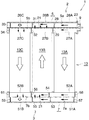
図1および図2において、エバポレータ(1)は、上下方向に間隔をおいて配置されたアルミニウム製上ヘッダタンク(2)およびアルミニウム製下ヘッダタンク(3)と、両ヘッダタンク(2)(3)の間に設けられた熱交換コア部(4)とを備えている。 1 and 2, the evaporator (1) includes an aluminum upper header tank (2) and an aluminum lower header tank (3) which are spaced apart in the vertical direction, and both header tanks (2) (3 ) And a heat exchange core section (4) provided between the two.
上ヘッダタンク(2)は、風下側(前側)に位置する風下側ヘッダ部(5)と、風上側(後側)に位置しかつ風下側ヘッダ部(5)に一体化された風上側ヘッダ部(6)とを備えている。ここでは、風下側ヘッダ部(5)と風上側ヘッダ部(6)とは、上ヘッダタンク(2)を垂直仕切部(2a)により前後に仕切ることによって設けられている。下ヘッダタンク(3)は、風下側(前側)に位置する風下側ヘッダ部(7)と、風上側(後側)に位置しかつ風下側ヘッダ部(7)に一体化された風上側ヘッダ部(8)とを備えている。ここでは、風下側ヘッダ部(7)と風上側ヘッダ部(8)とは、下ヘッダタンク(3)を垂直仕切部(3a)により前後に仕切ることによって設けられている。以下の説明において、上ヘッダタンク(2)の風下側ヘッダ部(5)を風下側上ヘッダ部、下ヘッダタンク(3)の風下側ヘッダ部(7)を風下側下ヘッダ部、上ヘッダタンク(2)の風上側ヘッダ部(6)を風上側上ヘッダ部、下ヘッダタンク(3)の風上側ヘッダ部(8)を風上側下ヘッダ部というものとする。風下側上ヘッダ部(5)の右端部に冷媒入口(9)が設けられ、風上側上ヘッダ部(6)の右端部に冷媒出口(11)が設けられている。 The upper header tank (2) has a leeward header part (5) located on the leeward side (front side) and an upwind header located on the leeward side (rear side) and integrated with the leeward header part (5). Part (6). Here, the leeward header section (5) and the leeward header section (6) are provided by partitioning the upper header tank (2) back and forth by the vertical partition section (2a). The lower header tank (3) has a leeward header section (7) located on the leeward side (front side) and an upwind header located on the leeward side (rear side) and integrated with the leeward header section (7). Part (8). Here, the leeward header section (7) and the leeward header section (8) are provided by partitioning the lower header tank (3) back and forth by the vertical partition section (3a). In the following description, the leeward header portion (5) of the upper header tank (2) is the leeward upper header portion, the leeward header portion (7) of the lower header tank (3) is the leeward lower header portion, and the upper header tank. The windward header section (6) of (2) is referred to as the windward upper header section, and the windward header section (8) of the lower header tank (3) is referred to as the windward lower header section. A refrigerant inlet (9) is provided at the right end of the leeward upper header (5), and a refrigerant outlet (11) is provided at the right end of the leeward upper header (6).
熱交換コア部(4)は、長手方向を上下方向に向けるとともに幅方向を通風方向に向けた状態で左右方向に間隔をおいて配置された複数のアルミニウム製扁平状熱交換チューブ(12)からなるチューブ列(13)(14)が、前後方向に並んで2列設けられ、各チューブ列(13)(14)の隣接する熱交換チューブ(12)どうしの間の通風間隙および左右両端の熱交換チューブ(12)の外側に、それぞれ前後両チューブ列(13)(14)の熱交換チューブ(12)に跨るようにアルミニウム製コルゲートフィン(15)が配置されて熱交換チューブ(12)にろう付され、左右両端のコルゲートフィン(15)の外側にそれぞれアルミニウム製サイドプレート(16)が配置されてコルゲートフィン(15)にろう付されることにより構成されている。風下側チューブ列(13)の熱交換チューブ(12)の上下両端部は、風下側上下両ヘッダ部(5)(7)内に突出するように挿入された状態で両ヘッダ部(5)(7)に連通状に接続され、風上側チューブ列(12)の熱交換チューブ(12)の上下両端部は、風上側上下両ヘッダ部(6)(8)内に突出するように挿入された状態で両ヘッダ部(6)(8)に連通状に接続されている。なお、風下側チューブ列(13)の熱交換チューブ(12)の数と風上側チューブ列(14)の熱交換チューブ(12)の数とは等しくなっている。 The heat exchange core section (4) is made up of a plurality of aluminum flat heat exchange tubes (12) arranged at intervals in the left-right direction with the longitudinal direction oriented in the vertical direction and the width direction directed in the ventilation direction. The tube rows (13) and (14) are arranged in two rows in the front-rear direction, and the ventilation gap between adjacent heat exchange tubes (12) in each tube row (13) and (14) and the heat at the left and right ends. Aluminum corrugated fins (15) are placed on the outside of the exchange tube (12) so as to straddle the heat exchange tubes (12) of both the front and rear tube rows (13) and (14). The aluminum side plates (16) are respectively arranged outside the corrugated fins (15) at both the left and right ends and brazed to the corrugated fins (15). The upper and lower ends of the heat exchange tubes (12) in the leeward side tube row (13) are inserted so as to protrude into both the upper and lower header portions (5) and (7) on the leeward side. 7) are connected in a continuous manner, and the upper and lower ends of the heat exchange tubes (12) of the windward tube row (12) are inserted so as to protrude into the windward upper and lower headers (6) and (8). In the state, it is connected to both header sections (6) and (8) in a continuous manner. The number of heat exchange tubes (12) in the leeward tube row (13) is equal to the number of heat exchange tubes (12) in the windward tube row (14).
図2〜図4に示すように、風下側チューブ列(13)には、左右方向に間隔をおいて配置された複数の熱交換チューブ(12)からなる3つのチューブ群(13A)(13B)(13C)が、右端から左端に向かって並んで設けられ、風上側チューブ列(14)には、左右方向に間隔をおいて配置された複数の熱交換チューブ(12)からなる2つ(風下側チューブ列(13)のチューブ群の数よりも1つ少ない数)のチューブ群(14A)(14B)が、左端から右端に向かって並んで設けられている。ここで、風下側チューブ列(13)の3つのチューブ群(13A)(13B)(13C)を冷媒入口(9)側端部(右端部)から他端部(左端部)に向かって第1〜第3チューブ群といい、風上側チューブ列(14)の2つのチューブ群(14A)(14B)を冷媒出口(11)とは反対側の端部(左端部)から冷媒出口(11)側端部(右端部)に向かって第4〜第5チューブ群というものとする。 As shown in FIGS. 2 to 4, the leeward side tube row (13) includes three tube groups (13 </ b> A) and (13 </ b> B) including a plurality of heat exchange tubes (12) arranged at intervals in the left-right direction. (13C) are arranged side by side from the right end to the left end, and the windward tube row (14) includes two (leeward) winds composed of a plurality of heat exchange tubes (12) spaced apart in the left-right direction. Tube groups (14A) and (14B), which are one less than the number of tube groups in the side tube row (13), are provided side by side from the left end to the right end. Here, the three tube groups (13A), (13B), and (13C) in the leeward side tube row (13) are moved from the refrigerant inlet (9) side end (right end) toward the other end (left end). ~ Third tube group, the two tube groups (14A) and (14B) in the windward tube row (14) are connected to the refrigerant outlet (11) side from the end (left end) opposite to the refrigerant outlet (11). It shall be called the 4th-5th tube group toward an end (right end).
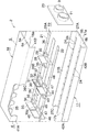
図5に詳細に示すように、上ヘッダタンク(2)は、風下側上ヘッダ部(5)および風上側上ヘッダ部(6)の下部を形成し、かつ両チューブ列(13)(14)の熱交換チューブ(12)が接続されたアルミニウム製第1部材(17)と、第1部材(17)にろう付されかつ第1部材(17)における熱交換チューブ(12)とは反対側(上側)を覆って風下側上ヘッダ部(5)および風上側上ヘッダ部(6)の上部を形成するアルミニウム製第2部材(18)と、第1部材(17)と第2部材(18)との間に配置され、かつ風下側上ヘッダ部(5)内および風上側上ヘッダ部(6)内をそれぞれ上下方向に2つの空間(5a)(5b)(6a)(6b)に仕切る前後両仕切部(21)(22)を有するアルミニウム製第3部材(19)と、冷媒入口(9)および冷媒出口(11)が設けられかつ第1〜第3部材(17)(18)(19)の右端部にろう付されたエンド部材(23)とを備えている。第1〜第3部材(17)(18)(19)およびエンド部材(23)は、たとえば両面にろう材層を有するアルミニウムブレージングシートによって形成されている。なお、第3部材(19)はアルミニウムベア材から形成されていてもよい。 As shown in detail in FIG. 5, the upper header tank (2) forms a lower part of the leeward upper header part (5) and the upper windward upper header part (6), and both the tube rows (13) (14). The aluminum first member (17) to which the heat exchange tube (12) is connected, and the first member (17) brazed to the opposite side of the first member (17) from the heat exchange tube (12) ( An aluminum second member (18) that covers the upper side and forms the upper part of the leeward upper header portion (5) and the windward upper header portion (6), and the first member (17) and the second member (18). Before and after dividing the inside of the leeward upper header (5) and the windward upper header (6) into two spaces (5a) (5b) (6a) (6b) An aluminum third member (19) having both partitions (21) and (22), a refrigerant inlet (9) and a refrigerant outlet (11) are provided, and the first to third members (17), (18) (19 ) And an end member (23) brazed to the right end. The first to third members (17), (18), (19) and the end member (23) are formed of, for example, an aluminum brazing sheet having a brazing material layer on both sides. The third member (19) may be formed from an aluminum bare material.
第1部材(17)は、風下側上ヘッダ部(5)の前側壁の下部および下壁、風上側上ヘッダ部(6)の後側壁の下部および下壁、ならびに仕切部(2a)の下部を構成する。第1部材(17)における風下側および風上側上ヘッダ部(5)(6)の下壁を構成する部分(17a)に、それぞれ前後方向に長いチューブ挿入穴(24)が左右方向に間隔をおいて形成されており、チューブ挿入穴(24)に熱交換チューブ(12)の上端部が挿入されて熱交換チューブ(12)が第1部材(17)にろう付されている。 The first member (17) includes a lower part and a lower wall of the front side wall of the leeward upper header part (5), a lower part and a lower wall of the rear side wall of the leeward upper header part (6), and a lower part of the partition part (2a). Configure. The tube insertion holes (24) that are long in the front-rear direction are spaced apart in the left-right direction in the part (17a) that forms the lower wall of the leeward side and the upwind header part (5), (6) in the first member (17). The upper end of the heat exchange tube (12) is inserted into the tube insertion hole (24), and the heat exchange tube (12) is brazed to the first member (17).
第2部材(18)は、風下側上ヘッダ部(5)の前側壁の上部および上壁、風上側上ヘッダ部(6)の後側壁の上部および上壁、ならびに仕切部(2a)の上部を構成する。第2部材(18)の仕切部(2a)の上部を構成する部分(18a)における第3チューブ群(13C)が設けられている位置に、その下端から複数の切り欠き(25)が左右方向に間隔をおいて形成されている。 The second member (18) includes an upper part and an upper wall of the front side wall of the leeward upper header part (5), an upper part and an upper wall of the rear side wall of the leeward upper header part (6), and an upper part of the partition part (2a). Configure. A plurality of notches (25) are provided in the left-right direction at the position where the third tube group (13C) is provided in the portion (18a) constituting the upper part of the partition part (2a) of the second member (18). Are formed at intervals.
第3部材(19)における風下側上ヘッダ部(5)内を上下方向に2つの空間(5a)(5b)に仕切る前側仕切部(21)と、同じく風上側上ヘッダ部(6)内を上下方向に2つの空間(6a)(6b)に仕切る後側仕切部(22)とは、第1部材(17)における仕切部(2a)の下部を構成する部分(17b)と、第2部材(18)における仕切部(2a)の上部を構成する部分(18a)との間に介在させられて両部分(17b)(18a)にろう付された連結部(19a)により一体に連結されている。そして、第2部材(18)の切り欠き(25)の下端が連結部(19a)により塞がれている。なお、前側仕切部(21)の前側縁部は第1部材(17)における風下側上ヘッダ部(5)の前側壁の下部を構成する部分と、第2部材(18)における風下側上ヘッダ部(5)の前側壁の上部を構成する部分との間に介在させられて両部分にろう付され、後側仕切部(22)の後側縁部は第1部材(17)における風上側上ヘッダ部(6)の後側壁の下部を構成する部分と、第2部材(18)における風上側上ヘッダ部(6)の後側壁の上部を構成する部分との間に介在させられて両部分にろう付されている。 In the third member (19) the leeward side upper header part (5) is divided into two spaces (5a) and (5b) in the vertical direction, and also in the leeward upper header part (6). The rear partitioning part (22) which divides into two spaces (6a) and (6b) in the vertical direction is a part (17b) constituting the lower part of the partitioning part (2a) in the first member (17) and the second member (18) are integrally connected by a connecting part (19a) that is interposed between the part (18a) constituting the upper part of the partition part (2a) and brazed to both parts (17b) (18a). Yes. And the lower end of the notch (25) of the 2nd member (18) is block | closed by the connection part (19a). In addition, the front side edge part of a front side partition part (21) is a part which comprises the lower part of the front side wall of the leeward side upper header part (5) in a 1st member (17), and the leeward side upper header in a 2nd member (18). Interposed between the parts constituting the upper part of the front side wall of the part (5) and brazed to both parts, the rear edge of the rear partition part (22) being the windward side of the first member (17) It is interposed between a part constituting the lower part of the rear side wall of the upper header part (6) and a part constituting the upper part of the rear side wall of the windward upper header part (6) in the second member (18). The part is brazed.
第3部材(19)の前側仕切部(21)における第1チューブ群(13A)と第2チューブ群(13B)との間の部分、および第2チューブ群(13B)と第3チューブ群(13C)との間の部分に、それぞれ前側仕切部(21)に切り曲げ加工を施すことによって、上下両空間(5a)(5b)内を上ヘッダタンク(2)の長さ方向に風下側チューブ列(13)のチューブ群(13A)(13B)(13C)と同数の区画(26A)(26B)(26C)および(27A)(27B)(27C)に分割する仕切壁(28)(29)および(31)(32)が、前側仕切部(21)と一体に形成されている。第1チューブ群(13A)と第2チューブ群(13B)との間および第2チューブ群(13B)と第3チューブ群(13C)との間に形成され、かつ上空間(5a)内を分割する仕切壁(28)および(31)と下空間(5b)内を分割する仕切壁(29)および(32)とは左右方向に若干ずれている。第3部材(19)の前側仕切部(21)における第3チューブ群(13C)よりも左側の部分に、前側仕切部(21)に切り曲げ加工を施すことによって、風下側上ヘッダ部(5)の上下両空間(5a)(5b)の左端部を閉鎖する閉鎖壁(33)(34)が、前側仕切部(21)と一体に形成されている。前側仕切部(21)の上下両閉鎖壁(33)(34)は左右方向に若干ずれている。したがって、風下側上ヘッダ部(5)の上下両空間(5a)(5b)内は、それぞれ仕切壁(28)(29)(31)(32)によって風下側チューブ列(13)のチューブ群(13A)(13B)(13C)と同数の区画(26A)(26B)(26C)および(27A)(27B)(27C)に分割されている。ここで、風下側上ヘッダ部(5)の上下両空間(5a)(5b)の3つの区画(26A)(26B)(26C)および(27A)(27B)(27C)を、冷媒入口(9)側端部(右端部)から他端部(左端部)に向かって第1〜第3区画というものとする。下空間(5b)の第1〜第3区画(27A)(27B)(27C)に、それぞれ第1〜第3チューブ群(13A)(13B)(13C)の熱交換チューブ(12)が通じている。さらに、上空間(5a)における冷媒入口(9)から最も遠い位置にある第3区画(26C)と、これに隣接する第2区画(26B)との間の仕切壁(31)に、両区画(26C)(26B)を通じさせる連通穴(39)が形成されている。 The portion between the first tube group (13A) and the second tube group (13B) in the front partitioning portion (21) of the third member (19), and the second tube group (13B) and the third tube group (13C ), The front partition (21) is cut and bent, so that the inside of the upper and lower spaces (5a) and (5b) in the length direction of the upper header tank (2) Partition walls (28) (29) and (13) divided into the same number of compartments (26A) (26B) (26C) and (27A) (27B) (27C) as the tube group (13A) (13B) (13C) in (13) (31) (32) are formed integrally with the front partition (21). It is formed between the first tube group (13A) and the second tube group (13B) and between the second tube group (13B) and the third tube group (13C), and the upper space (5a) is divided. The partition walls (28) and (31) and the partition walls (29) and (32) dividing the lower space (5b) are slightly shifted in the left-right direction. By cutting and bending the front partition (21) at the left side of the third tube group (13C) in the front partition (21) of the third member (19), the leeward upper header section (5 ) And the upper and lower spaces (5a) and (5b) are formed integrally with the front partitioning portion (21). The upper and lower closed walls (33), (34) of the front partition (21) are slightly shifted in the left-right direction. Therefore, inside the upper and lower spaces (5a) (5b) of the leeward upper header section (5), the tube groups (13) of the leeward tube row (13) are respectively separated by the partition walls (28) (29) (31) (32). It is divided into the same number of sections (26A) (26B) (26C) and (27A) (27B) (27C) as 13A) (13B) (13C). Here, the three sections (26A) (26B) (26C) and (27A) (27B) (27C) of the upper and lower spaces (5a) (5b) of the leeward upper header section (5) are connected to the refrigerant inlet (9 ) First to third sections from the side end (right end) toward the other end (left end). The heat exchange tubes (12) of the first to third tube groups (13A) (13B) (13C) are connected to the first to third sections (27A) (27B) (27C) of the lower space (5b), respectively. Yes. Furthermore, both partitions are formed in the partition wall (31) between the third partition (26C) located farthest from the refrigerant inlet (9) in the upper space (5a) and the second partition (26B) adjacent thereto. A communication hole (39) is formed through (26C) and (26B).
第3部材(19)における仕切壁(28)(29)(31)(32)および閉鎖壁(33)(34)が形成された前側仕切部(21)により仕切られた風下側上ヘッダ部(5)の上下両空間(5a)(5b)どうしは、前側仕切部(21)に切り曲げ加工を施すことにより形成された貫通穴(35)を介して通じさせられている。前側仕切部(21)における第1チューブ群(13A)と第2チューブ群(13B)との間の仕切壁(28)(29)よりも右側の部分に、その右端から下側の仕切壁(29)を形成することによりできた貫通穴(35)の近傍に至る左右方向に長い切り欠き(36)が形成されており、切り欠き(36)によって上下両空間(5a)(5b)が相互に通じさせられるとともに、冷媒入口(9)が上下両空間(5a)(5b)に通じさせられている。第3部材(19)の前側仕切部(21)における右側の下の仕切壁(29)および左側の上の仕切壁(31)を形成することによりできた2つの貫通穴(35)間に、左右方向に長い長穴(37)が貫通状に形成されており、この長穴(37)により上下両空間(5a)(5b)が通じさせられている。さらに、第3部材(19)の前側仕切部(21)における左側の下の仕切壁(32)および上の閉鎖壁(33)を形成することによりできた2つの貫通穴(35)間に、前後方向に長い複数の長穴(38)が左右方向に間隔をおいて貫通状に形成されており、この長穴(38)により上下両空間(5a)(5b)が通じさせられている。したがって、風下側上ヘッダ部(5)の下空間(5b)(上下方向内側空間)に、冷媒入口(9)から最も遠い位置にある最遠チューブ群である第3チューブ群(13C)の熱交換チューブ(12)が通じる第3区画(27C)(上下方向内側最遠区画)が設けられるとともに、同じく上空間(5a)(上下方向外側空間)に、下空間(5b)の第3区画(27C)に通じる第3区画(26C)(上下方向外側最遠区画)が設けられ、両第3区画(27C)(26C)どうしが通じさせられている。 The leeward upper header section partitioned by the front partition section (21) in which the partition walls (28) (29) (31) (32) and the closing walls (33) (34) in the third member (19) are formed. The upper and lower spaces (5a) and (5b) of 5) are communicated with each other through a through hole (35) formed by cutting and bending the front partition (21). On the right side of the partition wall (28) (29) between the first tube group (13A) and the second tube group (13B) in the front partition (21), the partition wall (from the right end to the lower partition wall ( 29), a long notch (36) is formed in the left-right direction to the vicinity of the through-hole (35) formed by forming the upper and lower spaces (5a) (5b) with each other by the notch (36). The refrigerant inlet (9) is communicated with both the upper and lower spaces (5a) and (5b). Between the two through holes (35) formed by forming the lower partition wall (29) on the right side and the upper partition wall (31) on the left side in the front partition (21) of the third member (19), A long hole (37) that is long in the left-right direction is formed in a penetrating manner, and the upper and lower spaces (5a) and (5b) are communicated with each other by the long hole (37). Further, between the two through holes (35) formed by forming the lower partition wall (32) on the left side and the upper closing wall (33) in the front partition (21) of the third member (19), A plurality of long holes (38) that are long in the front-rear direction are formed in a penetrating manner at intervals in the left-right direction, and the upper and lower spaces (5a) (5b) are communicated with each other by the long holes (38). Therefore, the heat of the third tube group (13C), which is the farthest tube group located farthest from the refrigerant inlet (9), in the lower space (5b) (vertical inner space) of the leeward upper header portion (5). A third section (27C) (upward / downward innermost section) through which the exchange tube (12) communicates is provided, and in the upper space (5a) (upper / lower outer space), the third section of the lower space (5b) ( 27C) is provided with a third section (26C) (the farthest outermost section in the vertical direction), and the third sections (27C) and (26C) are communicated with each other.
第3部材(19)の後側仕切部(22)における第4チューブ群(14A)と第5チューブ群(14B)との間の部分に、後側仕切部(22)に切り曲げ加工を施すことによって、上下両空間(6a)(6b)内を上ヘッダタンク(2)の長さ方向に風上側チューブ列(14)のチューブ群(14A)(14B)と同数の区画(41A)(41B)および(42A)(42B)に分割する仕切壁(43)(44)が、後側仕切部(22)と一体に形成されている。上下両仕切壁(43)(44)は左右方向に若干ずれている。第3部材(19)の後側仕切部(22)における第4チューブ群(14A)よりも左側の部分に、後側仕切部(22)に切り曲げ加工を施すことによって、風上側上ヘッダ部(6)の上下両空間(6a)(6b)の左端部を閉鎖する閉鎖壁(45)(46)が、後側仕切部(22)と一体に形成されている。後側仕切部(22)の上下両閉鎖壁(45)(46)は左右方向に若干ずれている。したがって、風上側上ヘッダ部(6)の上下両空間(6a)(6b)内は、それぞれ仕切壁(43)(44)によって風上側チューブ列(14)のチューブ群(14A)(14B)と同数の区画(41A)(41B)および(42A)(42B)に分割されている。ここで、風上側上ヘッダ部(6)の上下両空間(6a)(6b)の2つの区画(41A)(41B)および(42A)(42B)を、冷媒出口(11)とは反対側の端部(左端部)から冷媒出口(11)側端部(右端部)に向かって第4〜第5区画というものとする。下空間(6b)の第4〜第5区画(42A)(42B)に、それぞれ第4〜第5チューブ群(14A)(14B)の熱交換チューブ(12)が通じている。 The rear partition portion (22) is cut and bent at a portion between the fourth tube group (14A) and the fifth tube group (14B) in the rear partition portion (22) of the third member (19). Thus, in the upper and lower spaces (6a) (6b), the same number of compartments (41A) (41B) as the tube groups (14A) (14B) of the windward tube row (14) in the length direction of the upper header tank (2) ) And (42A) (42B), partition walls (43) and (44) are formed integrally with the rear partition (22). The upper and lower partition walls (43) and (44) are slightly shifted in the left-right direction. A windward upper header section is formed by cutting and bending the rear partition section (22) at the left side of the fourth tube group (14A) in the rear partition section (22) of the third member (19). Closed walls (45) and (46) for closing the left ends of the upper and lower spaces (6a) and (6b) of (6) are formed integrally with the rear partition (22). The upper and lower closing walls (45), (46) of the rear partition (22) are slightly shifted in the left-right direction. Accordingly, the upper and lower spaces (6a) and (6b) of the windward upper header section (6) are respectively connected to the tube groups (14A) and (14B) of the windward tube row (14) by the partition walls (43) and (44). It is divided into the same number of sections (41A) (41B) and (42A) (42B). Here, the two sections (41A) (41B) and (42A) (42B) of the upper and lower spaces (6a) (6b) of the windward upper header section (6) are placed on the side opposite to the refrigerant outlet (11). From the end (left end) to the refrigerant outlet (11) side end (right end), it is referred to as fourth to fifth sections. The heat exchange tubes (12) of the fourth to fifth tube groups (14A) and (14B) communicate with the fourth to fifth sections (42A) and (42B) of the lower space (6b), respectively.
第3部材(19)における仕切壁(43)(44)および閉鎖壁(45)(46)が形成された後側仕切部(22)により仕切られた風上側上ヘッダ部(6)の上下両空間(6a)(6b)どうしは、後側仕切部(22)に切り曲げ加工を施すことにより形成された貫通穴(47)を介して通じさせられている。後側仕切部(22)における仕切壁(43)(44)よりも右側の部分に、その右端から上側の仕切壁(43)を形成することによりできた貫通穴(47)の近傍に至る左右方向に長い切り欠き(48)が形成されており、切り欠き(48)によって上下両空間(6a)(6b)が相互に通じさせられるとともに、冷媒出口(11)が上下両空間(6a)(6b)に通じさせられている。第3部材(19)の後側仕切部(22)における下の仕切壁(44)および上の閉鎖壁(45)を形成することによりできた2つの貫通穴(47)間に、左右方向に長い長穴(49)が貫通状に形成されており、この長穴(49)により上下両空間(6a)(6b)が通じさせられている。 Upper and lower sides of the windward upper header section (6) partitioned by the rear partition section (22) in which the partition walls (43) (44) and the closing walls (45) (46) are formed in the third member (19) The spaces (6a) and (6b) are communicated with each other through a through hole (47) formed by cutting and bending the rear partition (22). The left and right sides from the right end of the rear partition (22) to the right side of the partition walls (43) and (44) and the vicinity of the through hole (47) formed by forming the upper partition wall (43) A long notch (48) is formed in the direction, the notch (48) allows the upper and lower spaces (6a) and (6b) to communicate with each other, and the refrigerant outlet (11) has both upper and lower spaces (6a) ( 6b). Between the two through holes (47) formed by forming the lower partition wall (44) and the upper closing wall (45) in the rear partition (22) of the third member (19), in the left-right direction A long elongated hole (49) is formed in a penetrating manner, and the upper and lower spaces (6a) and (6b) are communicated with each other by the elongated hole (49).
風下側上ヘッダ部(5)の上空間(5a)における冷媒入口(9)から最も遠い位置にある第3区画(26C)(上下方向外側最遠区画)と、風上側上ヘッダ部(6)の上空間(6a)における冷媒出口(11)から最も遠い位置にある第4区画(41A)(上下方向内側最遠区画)とは、第2部材(18)における仕切部(2a)の上部を構成する部分(18a)に形成され、かつ第3部材(19)の連結部(19a)により塞がれた切り欠き(25)を介して通じさせられている。 The third section (26C) (upward / downward outermost section) located farthest from the refrigerant inlet (9) in the upper space (5a) of the leeward upper header section (5), and the windward upper header section (6) In the upper space (6a), the fourth section (41A) (the farthest innermost section in the vertical direction) farthest from the refrigerant outlet (11) is the upper part of the partition (2a) in the second member (18). It is communicated via a notch (25) formed in the constituting part (18a) and closed by the connecting part (19a) of the third member (19).
なお、風下側上ヘッダ部(5)における第1区画(26A)(27A)と第2区画(26B)(27B)の左右方向の合計長さは、風上側上ヘッダ部(6)における第5区画(41B)(42B)の左右方向の長さと等しく、風下側上ヘッダ部(5)の第3区画(26C)(27C)の左右方向の長さは、風上側上ヘッダ部(6)の第4区画(41A)(42A)の左右方向の長さと等しくなっている。 The total length in the left-right direction of the first section (26A) (27A) and the second section (26B) (27B) in the leeward upper header section (5) is the fifth length in the leeward upper header section (6). The length in the left-right direction of the third section (26C) (27C) of the leeward upper header section (5) is equal to the length in the left-right direction of the sections (41B) (42B). It is equal to the length of the 4th division (41A) (42A) in the left-right direction.
図6に詳細に示すように、下ヘッダタンク(3)は上ヘッダタンク(2)とほぼ同様な構成であり、上ヘッダタンク(2)とは上下逆向きに配置されている。そして、第1部材(17)が風下側下ヘッダ部(7)および風上側下ヘッダ部(8)の上部を形成し、第2部材(18)が第1部材(17)における熱交換チューブ(12)とは反対側(下側)を覆って風下側下ヘッダ部(7)および風上側下ヘッダ部(8)の下部を形成する。また、第3部材(19)の前側仕切部(21)が風下側下ヘッダ部(7)内を上下方向に2つの空間(7b)(7a)に仕切り、後側仕切部(22)が風上側下ヘッダ部(8)内を上下方向に2つの空間(8b)(8a)に仕切る。下ヘッダタンク(3)の第1部材(17)および第2部材(18)は上ヘッダタンク(2)の第1部材(17)および第2部材(18)と同一の構成である。なお、下ヘッダタンク(3)には冷媒入口(9)および冷媒出口(11)は設けられておらず、したがってエンド部材も備えていない。 As shown in detail in FIG. 6, the lower header tank (3) has substantially the same configuration as the upper header tank (2), and is disposed upside down with respect to the upper header tank (2). And the 1st member (17) forms the upper part of the leeward lower header part (7) and the windward lower header part (8), and the 2nd member (18) is the heat exchange tube (1) in the 1st member (17). Cover the opposite side (lower side) to 12) and form the lower part of the leeward lower header part (7) and the lower part of the leeward lower header part (8). The front partition (21) of the third member (19) partitions the leeward lower header (7) vertically into two spaces (7b) (7a), and the rear partition (22) The upper lower header portion (8) is partitioned into two spaces (8b) and (8a) in the vertical direction. The first member (17) and the second member (18) of the lower header tank (3) have the same configuration as the first member (17) and the second member (18) of the upper header tank (2). The lower header tank (3) is not provided with the refrigerant inlet (9) and the refrigerant outlet (11), and therefore has no end member.
第3部材(19)の前側仕切部(21)における第2チューブ群(13B)と第3チューブ群(13C)との間の部分に、前側仕切部(21)に切り曲げ加工を施すことによって、上下両空間(7b)(7a)内を下ヘッダタンク(3)の長さ方向に風下側チューブ列(13)のチューブ群(13A)(13B)(13C)の数よりも1つ少ない区画(52A)(52B)および(51A)(51B)に分割する仕切壁(56)(55)が、前側仕切部(21)と一体に形成されている。上下の仕切壁(56)(55)は左右方向に若干ずれている。第3部材(19)の前側仕切部(21)における第1チューブ群(13A)よりも右側の部分に、前側仕切部(21)に切り曲げ加工を施すことによって、風下側下ヘッダ部(7)の上下両空間(7b)(7a)の右端部を閉鎖する閉鎖壁(58)(57)が、前側仕切部(21)と一体に形成されている。また、前側仕切部(21)における第3チューブ群(13C)よりも左側の部分に、前側仕切部(21)に切り曲げ加工を施すことによって、風下側下ヘッダ部(7)の上下両空間(7b)(7a)の左端部を閉鎖する閉鎖壁(61)(59)が、前側仕切部(21)と一体に形成されている。前側仕切部(21)の上下両閉鎖壁(58)(57)および(61)(59)は左右方向に若干ずれている。したがって、風下側下ヘッダ部(7)の上下両空間(7b)(7a)内は、それぞれ仕切壁(56)(55)によって風下側チューブ列(13)のチューブ群(13A)(13B)(13C)よりも1つ少ない数の区画(52A)(52B)および(51A)(51B)に分割されている。ここで、風下側下ヘッダ部(7)の上下両空間(7b)(7a)の2つの区画(52A)(52B)および(51A)(51B)を、冷媒入口(9)側端部(右端部)から他端部(左端部)に向かって第1〜第2区画というものとする。上空間(7b)の第1区画(52A)に第1〜第2チューブ群(13A)(13B)の熱交換チューブ(12)が通じるとともに、第2区画(52B)に第3チューブ群(13C)の熱交換チューブ(12)が通じている。また、第3部材(19)の前側仕切部(21)における第2チューブ群(13B)の左右方向の範囲内の部分に、前側仕切部(21)に切り曲げ加工を施すことによって、上下両空間(7b)(7a)の第1区画(52A)(51A)内を下ヘッダタンク(3)の長さ方向に分割しかつ第2チューブ群(13B)への冷媒の分流を制御する分流制御壁(54)(53)が、前側仕切部(21)と一体に形成されている。上下の分流制御壁(54)(53)は左右方向に若干ずれている。分流制御壁(54)(53)には、連通穴(65)(64)が形成されている。 By cutting and bending the front partition (21) at the portion between the second tube group (13B) and the third tube group (13C) in the front partition (21) of the third member (19) The space in the upper and lower spaces (7b) (7a) is one less than the number of tube groups (13A) (13B) (13C) in the leeward tube row (13) in the length direction of the lower header tank (3) Partition walls (56) and (55) that are divided into (52A), (52B), and (51A) and (51B) are formed integrally with the front partition (21). The upper and lower partition walls (56) (55) are slightly shifted in the left-right direction. By cutting and bending the front partition (21) at the right side of the first tube group (13A) in the front partition (21) of the third member (19), the leeward lower header section (7 Closed walls (58) and (57) for closing the right end portions of the upper and lower spaces (7b) and (7a) are formed integrally with the front partition (21). Also, by cutting and bending the front partition (21) at the left side of the third tube group (13C) in the front partition (21), the upper and lower spaces of the leeward lower header (7) (7b) A closed wall (61) (59) for closing the left end of (7a) is formed integrally with the front partition (21). The upper and lower closed walls (58) (57) and (61) (59) of the front partition (21) are slightly shifted in the left-right direction. Therefore, in the upper and lower spaces (7b) (7a) of the leeward lower header portion (7), the tube groups (13A) (13B) (13B) of the leeward tube row (13) are respectively separated by the partition walls (56) (55). It is divided into sections (52A) (52B) and (51A) (51B), which are one less than 13C). Here, the two compartments (52A) (52B) and (51A) (51B) of the upper and lower spaces (7b) (7a) of the leeward side lower header (7) are connected to the refrigerant inlet (9) side end (right end Part) toward the other end part (left end part). The heat exchange tubes (12) of the first to second tube groups (13A) and (13B) communicate with the first section (52A) of the upper space (7b), and the third tube group (13C) to the second section (52B). ) Through the heat exchange tube (12). In addition, by cutting and bending the front partition (21) in the left and right range of the second tube group (13B) in the front partition (21) of the third member (19), Dividing control that divides the inside of the first section (52A) (51A) of the space (7b) (7a) in the length direction of the lower header tank (3) and controls the dividing of the refrigerant to the second tube group (13B) Walls (54) and (53) are formed integrally with the front partition (21). The upper and lower shunt control walls (54) and (53) are slightly shifted in the left-right direction. Communication holes (65) and (64) are formed in the flow dividing control walls (54) and (53).
第3部材(19)における仕切壁(56)(55)、分流制御壁(54)(53)および閉鎖壁(58)(57)(61)(59)が形成された前側仕切部(21)により仕切られた風下側下ヘッダ部(7)の上下両空間(7b)(7a)どうしは、前側仕切部(21)に切り曲げ加工を施すことにより形成された貫通穴(62)を介して通じさせられている。前側仕切部(21)における上の分流制御壁(54)および下の仕切壁(55)を形成することによりできた2つの貫通穴(62)間、下の分流制御壁(53)および右側の下の閉鎖壁(57)を形成することによりできた2つの貫通穴(62)間、ならびに上の仕切壁(56)および左側の下の閉鎖壁(59)を形成することによりできた2つの貫通穴(62)間に、それぞれ左右方向に長い長穴(63)が貫通状に形成されており、この長穴(63)により上下両空間(7b)(7a)が通じさせられている。 Front partition (21) in which partition walls (56) (55), flow control walls (54) (53) and closed walls (58) (57) (61) (59) are formed in the third member (19) The upper and lower spaces (7b) and (7a) of the leeward lower header section (7) partitioned by the through holes (62) formed by cutting and bending the front partition section (21). It is made to communicate. Between the two through holes (62) formed by forming the upper flow control wall (54) and the lower partition wall (55) in the front partition (21), the lower flow control wall (53) and the right Between the two through-holes (62) made by forming the lower closing wall (57), and the two made by forming the upper partition wall (56) and the lower lower closing wall (59) A long hole (63) that is long in the left-right direction is formed between the through holes (62) in the left-right direction, and the upper and lower spaces (7b) (7a) are communicated with each other by the long holes (63).
第3部材(19)の後側仕切部(22)の左右両端部に、後側仕切部(22)に切り曲げ加工を施すことによって、風上側下ヘッダ部(8)の上下両空間(8b)(8a)の左右両端部を閉鎖する閉鎖壁(67)(66)および(69)(68)が、後側仕切部(22)と一体に形成されている。後側仕切部(22)の左右両端の閉鎖壁(67)(66)および(69)(68)はそれぞれ左右方向に若干ずれている。したがって、風上側下ヘッダ部(8)の上下両空間(8b)(8a)内の全体が、風上側チューブ列(14)のチューブ群(14A)(14B)よりも1つ少ない数の区画(74)(73)となっている。ここで、当該区画(74)(73)を第3区画というものとする。上空間(8b)の第3区画(74)に、第4〜第5チューブ群(14A)(14B)のすべての熱交換チューブ(12)が通じている。また、第3部材(19)の後側仕切部(22)における第5チューブ群(14B)の左右方向の範囲内の部分に、後側仕切部(22)に切り曲げ加工を施すことによって、上下両空間(8b)(8a)の第3区画(74)(73)内を下ヘッダタンク(3)の長さ方向に分割しかつ第5チューブ群(14B)への冷媒の分流を制御する分流制御壁(87)(86)が、後側仕切部(22)と一体に形成されている。上下の分流制御壁(87)(86)は、前側仕切部(21)の仕切壁(56)(55)と分流制御壁(54)(53)との間に位置している。上下の分流制御壁(87)(86)は左右方向に若干ずれている。下側の分流制御壁(86)には、連通穴(88)が形成されている。 By cutting and bending the rear partition (22) at the left and right ends of the rear partition (22) of the third member (19), the upper and lower spaces (8b) ) (8a), closed walls (67), (66), and (69), (68) are formed integrally with the rear partition (22). The closing walls (67), (66) and (69), (68) at the left and right ends of the rear partition (22) are slightly shifted in the left-right direction. Therefore, the whole of the upper and lower spaces (8b) (8a) of the windward lower header portion (8) is one section less than the number of the tube groups (14A) (14B) of the windward tube row (14) ( 74) (73). Here, the section (74) (73) is referred to as a third section. All the heat exchange tubes (12) of the fourth to fifth tube groups (14A) and (14B) communicate with the third section (74) of the upper space (8b). Further, by cutting and bending the rear partition (22) in the left and right range of the fifth tube group (14B) in the rear partition (22) of the third member (19), The inside of the third section (74) (73) of the upper and lower spaces (8b) (8a) is divided in the length direction of the lower header tank (3) and the flow of the refrigerant to the fifth tube group (14B) is controlled. The flow dividing control walls (87) and (86) are formed integrally with the rear partition (22). The upper and lower flow dividing control walls (87) and (86) are located between the partition walls (56) and (55) of the front partition (21) and the flow dividing control walls (54) and (53). The upper and lower shunt control walls (87) and (86) are slightly shifted in the left-right direction. A communication hole (88) is formed in the lower diversion control wall (86).
第3部材(19)における閉鎖壁(67)(66)(69)(68)および分流制御壁(87)(86)が形成された後側仕切部(22)により仕切られた風上側下ヘッダ部(8)の上下両空間(8b)(8a)どうしは、後側仕切部(22)に切り曲げ加工を施すことにより形成された貫通穴(71)を介して通じさせられている。後側仕切部(22)における左端の下の閉鎖壁(66)および上側の分流制御壁(87)を形成することによりできた2つの貫通穴(71)間、ならびに右端の下の閉鎖壁(68)および下側の分流制御壁(86)を形成することによりできた2つの貫通穴(71)間に、それぞれ左右方向に長い長穴(72)が貫通状に形成されており、この長穴(72)により上下両空間(8b)(8a)が通じさせられている。 Upwind lower header partitioned by the rear partition portion (22) formed with the closed walls (67) (66) (69) (68) and the flow dividing control walls (87) (86) in the third member (19) The upper and lower spaces (8b) and (8a) of the portion (8) are communicated with each other through a through hole (71) formed by cutting and bending the rear partition (22). Between the two through holes (71) formed by forming the closing wall (66) below the left end and the upper flow dividing control wall (87) in the rear partition (22), and the closing wall below the right end ( 68) and between the two through holes (71) formed by forming the lower flow dividing control wall (86), long elongated holes (72) are formed in the left and right directions, respectively. The upper and lower spaces (8b) and (8a) are communicated by the hole (72).
風下側下ヘッダ部(7)の下空間(7a)の第2区画(51B)と、風上側下ヘッダ部(8)の下空間(8a)の第3区画(73)は、第2部材(18)における仕切部(3a)の下部を構成する部分(18a)に形成され、かつ第3部材(19)の連結部(19a)により塞がれた切り欠き(25)を介して通じさせられている。 The second section (51B) of the lower space (7a) of the leeward lower header section (7) and the third section (73) of the lower space (8a) of the leeward lower header section (8) are second members ( 18) is formed in a part (18a) constituting the lower part of the partition part (3a) and is communicated through a notch (25) closed by the connecting part (19a) of the third member (19). ing.
なお、風下側下ヘッダ部(7)における第1〜第2区画(52A)(52B)(51A)(51B)の左右方向の合計長さは、風上側下ヘッダ部(8)の第3区画(74)(73)の左右方向の長さと等しくなっている。 The total length of the first and second sections (52A), (52B), (51A), and (51B) in the leeward lower header section (7) is the third section of the leeward lower header section (8). (74) It is equal to the length in the left-right direction of (73).
上述のようにして冷媒入口(9)、冷媒出口(11)、切り欠き(25)、区画(26A)(26B)(26C)(27A)(27B)(27C)、仕切壁(28)(29)(31)(32)、貫通穴(35)、切り欠き(36)、長穴(37)(38)、連通穴(39)、区画(41A)(41B)(42A)(42B)、仕切壁(43)(44)、貫通穴(47)、切り欠き(48)、長穴(49)、区画(51A)(51B)(52A)(52B)、分流制御壁(53)(54)、仕切壁(55)(56)、貫通穴(62)、長穴(63)、連通穴(64)(65)、分流制御壁(86)(87)、連通穴(88)、貫通穴(71)、長穴(72)および区画(73)(74)が設けられることによって、冷媒は、第1チューブ群(13A)、冷媒入口(9)から最も遠い位置にある第3チューブ群(13C)(風下側チューブ列(13)の最遠チューブ群)および冷媒出口(11)から最も遠い位置にある第4チューブ群(14A)(風上側チューブ列(14)の最遠チューブ群)の熱交換チューブ(12)内を上から下に流れることになり、これらのチューブ群(13A)(13C)(14A)が下降流チューブ群となっている。また、冷媒は、第2チューブ群(13B)および第5チューブ群(14B)の熱交換チューブ(12)内を下から上に流れることになり、これらのチューブ群(13B)(14B)が上昇流チューブ群となっている。風下側チューブ列(13)における冷媒入口(9)から最も遠い位置にある第3チューブ群(13C)(最遠チューブ群)、および風上側チューブ列(14)における冷媒出口(11)から最も遠い位置にある第4チューブ群(14A)(最遠チューブ群)の熱交換チューブ(12)における冷媒の流れ方向は同一方向である。 Refrigerant inlet (9), refrigerant outlet (11), notch (25), compartments (26A) (26B) (26C) (27A) (27B) (27C), partition walls (28) (29) as described above ) (31) (32), Through hole (35), Notch (36), Slotted hole (37) (38), Communication hole (39), Partition (41A) (41B) (42A) (42B), Partition Wall (43) (44), Through hole (47), Notch (48), Slotted hole (49), Partition (51A) (51B) (52A) (52B), Shunt flow control wall (53) (54), Partition wall (55) (56), Through hole (62), Long hole (63), Communication hole (64) (65), Flow control wall (86) (87), Communication hole (88), Through hole (71 ), The long hole (72) and the compartments (73) and (74), the refrigerant flows through the first tube group (13A) and the third tube group (13C) located farthest from the refrigerant inlet (9). Heat exchange of (the farthest tube group in the leeward tube row (13)) and the fourth tube group (14A) (the farthest tube group in the windward tube row (14)) farthest from the refrigerant outlet (11) The tube (12) will flow from top to bottom, and these tube groups (13A) (13C) (14A) It has become a downward flow tube group. In addition, the refrigerant flows from the bottom to the top in the heat exchange tubes (12) of the second tube group (13B) and the fifth tube group (14B), and these tube groups (13B) (14B) rise. It is a flow tube group. The third tube group (13C) (the farthest tube group) located farthest from the refrigerant inlet (9) in the leeward tube row (13) and the farthest from the refrigerant outlet (11) in the windward tube row (14) The flow direction of the refrigerant in the heat exchange tubes (12) of the fourth tube group (14A) (farthest tube group) at the same position is the same direction.
したがって、冷媒入口(9)から流入した冷媒は、次のように2つの経路を流れて冷媒出口(11)から流出するようになされている。第1の経路は、第1区画(26A)(27A)、第1チューブ群(13A)、第1区画(52A)(51A)、第2チューブ群(13B)、第2区画(27B)(26B)、第3区画(26C)(27C)、第4区画(41A)(42A)、第4チューブ群(14A)、第3区画(74)(73)、第5チューブ群(14B)および第5区画(42B)(41B)であり、第2の経路は、第1区画(26A)(27A)、第1チューブ群(13A)、第1区画(52A)(51A)、第2チューブ群(13B)、第2区画(27B)(26B)、第3区画(26C)(27C)、第3チューブ群(13C)、第2区画(52B)(51B)、第3区画(73)(74)、第5チューブ群(14B)および第5区画(42B)(41B)である。上記第1の経路において、冷媒は、風下側上ヘッダ部(5)の上空間(5a)の第3区画(26C)から切り欠き(25)を通って風上側上ヘッダ部(6)の上空間(6a)の第4区画(41A)内に流入する。また、上記第2の経路において、冷媒は、風下側下ヘッダ部(7)の下空間(7a)の第2区画(51B)から切り欠き(25)を通って風上側下ヘッダ部(8)の下空間(8a)の第3区画(73)内に流入する。 Therefore, the refrigerant flowing in from the refrigerant inlet (9) flows through the two paths as follows and flows out from the refrigerant outlet (11). The first path consists of the first section (26A) (27A), the first tube group (13A), the first section (52A) (51A), the second tube group (13B), and the second section (27B) (26B). ), Third section (26C) (27C), fourth section (41A) (42A), fourth tube group (14A), third section (74) (73), fifth tube group (14B) and fifth The second path is the first section (26A) (27A), the first tube group (13A), the first section (52A) (51A), and the second tube group (13B). ), Second section (27B) (26B), third section (26C) (27C), third tube group (13C), second section (52B) (51B), third section (73) (74), The fifth tube group (14B) and the fifth section (42B) (41B). In the first path, the refrigerant passes through the notch (25) from the third section (26C) of the upper space (5a) of the leeward upper header portion (5) and passes over the upper windward header portion (6). It flows into the fourth section (41A) of the space (6a). In the second path, the refrigerant passes through the notch (25) from the second section (51B) of the lower space (7a) of the leeward lower header portion (7), and passes through the notch (25). Flows into the third section (73) of the lower space (8a).
上述したエバポレータ(1)は、圧縮機、冷媒冷却器としてのコンデンサおよび減圧器としての膨張弁とともに冷凍サイクルを構成し、カーエアコンとして車両、たとえば自動車に搭載される。カーエアコンの稼働時には、圧縮機、コンデンサおよび膨張弁を通過した冷媒が、上述した2つの経路を通って、冷媒入口(9)から流入するとともに冷媒出口(11)から流出し、冷媒が風下側チューブ列(13)の熱交換チューブ(12)内、および風上側チューブ列(14)の熱交換チューブ(12)内を流れる間に、熱交換コア部(4)の通風間隙を通過する空気(図1および図2矢印X参照)と熱交換をし、空気は冷却され、冷媒は気相となって流出する。 The evaporator (1) described above constitutes a refrigeration cycle together with a compressor, a condenser as a refrigerant cooler, and an expansion valve as a decompressor, and is mounted on a vehicle, for example, an automobile, as a car air conditioner. During the operation of the car air conditioner, the refrigerant that has passed through the compressor, the condenser, and the expansion valve flows in from the refrigerant inlet (9) and out of the refrigerant outlet (11) through the above-described two paths, and the refrigerant is on the leeward side. While passing through the heat exchange tube (12) of the tube row (13) and the heat exchange tube (12) of the windward tube row (14), the air passing through the ventilation gap of the heat exchange core portion (4) ( 1 and FIG. 2 (see arrow X), heat is exchanged, air is cooled, and refrigerant flows out as a gas phase.
この発明による熱交換器は、カーエアコンを構成する冷凍サイクルのエバポレータに好適に用いられる。 The heat exchanger according to the present invention is suitably used for an evaporator of a refrigeration cycle constituting a car air conditioner.
(1):エバポレータ(熱交換器)
(2):上ヘッダタンク
(2a):仕切部
(3):下ヘッダタンク
(3a):仕切部
(5):上ヘッダタンクの風下側ヘッダ部(風下側上ヘッダ部)
(5a):上空間
(5b):下空間
(6):上ヘッダタンクの風上側ヘッダ部(風上側上ヘッダ部)
(6a):上空間
(6b):下空間
(7):下ヘッダタンクの風下側ヘッダ部(風下側下ヘッダ部)
(7b):上空間
(7a):下空間
(8):下ヘッダタンクの風上側ヘッダ部(風上側下ヘッダ部)
(8b):上空間
(8a):下空間
(9):冷媒入口
(11):冷媒出口
(12):熱交換チューブ
(13):風下側チューブ列
(13A)(13B)(13C):第1〜第3チューブ群
(14):風上側チューブ列
(14A)(14B):第4〜第5チューブ群
(17):第1部材
(18):第2部材
(19):第3部材
(21):前側仕切部
(22):後側仕切部
(26A)(26B)(26C)(27A)(27B)(27C):風下側上ヘッダ部の第1〜第3区画
(28)(29)(31)(32)(43)(44)(55)(56):仕切壁
(33)(34)(45)(46)(57)(58)(59)(61)(66)(67):閉鎖壁
(35)(47)(63)(72):貫通穴
(39):連通穴
(41A)(41B)(42A)(42B):風上側上ヘッダ部の第4〜第5区画
(51A)(51B)(52A)(52B):風下側下ヘッダ部の第1〜第2区画
(73)(74):風上側下ヘッダ部の第3区画
(1): Evaporator (heat exchanger)
(2): Upper header tank
(2a): Partition
(3): Lower header tank
(3a): Partition
(5): Upper header tank leeward header (leeward upper header)
(5a): Upper space
(5b): Lower space
(6): Upward header section of the upper header tank (upstream upper header section)
(6a): Upper space
(6b): Lower space
(7): Lower header tank leeward header (leeward lower header)
(7b): Upper space
(7a): Lower space
(8): Windward header section of the lower header tank (windward lower header section)
(8b): Upper space
(8a): Lower space
(9): Refrigerant inlet
(11): Refrigerant outlet
(12): Heat exchange tube
(13): Downward tube row
(13A) (13B) (13C): First to third tube groups
(14): Windward tube row
(14A) (14B): Fourth to fifth tube groups
(17): First member
(18): Second member
(19): Third member
(21): Front partition
(22): Rear partition
(26A) (26B) (26C) (27A) (27B) (27C): First to third sections of the leeward upper header section
(28) (29) (31) (32) (43) (44) (55) (56): Partition wall
(33) (34) (45) (46) (57) (58) (59) (61) (66) (67): Closed wall
(35) (47) (63) (72): Through hole
(39): Communication hole
(41A) (41B) (42A) (42B): Fourth to fifth sections of the upwind header section
(51A) (51B) (52A) (52B): First to second sections of the leeward lower header section
(73) (74): Third section of the upwind header section
Claims (3)
各ヘッダタンクが、熱交換チューブが接続された第1部材、第1部材に接合されかつ第1部材における熱交換チューブとは反対側を覆う第2部材、ならびに第1部材と第2部材との間に配置され、かつ両ヘッダタンクの風下側および風上側ヘッダ部内をそれぞれ上下方向に2つの空間に仕切る仕切部を有する第3部材を備えており、両ヘッダタンクの風下側および風上側ヘッダ部に設けられた全ての上下両空間のうち少なくとも1つの空間内が、第3部材の仕切部に切り曲げ加工を施すことにより形成された仕切壁によってヘッダタンクの長さ方向に複数の区画に分割され、仕切壁が形成された仕切部により仕切られた上下両側の空間どうしが、仕切部に切り曲げ加工を施すことにより形成された貫通穴を介して通じさせられており、
冷媒入口および冷媒出口を有する前記一方のヘッダタンクの風下側および風上側ヘッダ部の他端部、ならびに他方のヘッダタンクの風下側および風上側ヘッダ部の両端部が、それぞれ第3部材の仕切部に切り曲げ加工を施すことにより形成された閉鎖壁によって閉鎖されている熱交換器。 Between a pair of header tanks arranged at intervals in the vertical direction, the header tanks are arranged at intervals in the length direction of the header tank with the longitudinal direction facing the vertical direction. A plurality of rows of tube tubes made of a plurality of heat exchange tubes connected to each other are provided at intervals in the ventilation direction, and each header tank is provided in a row in the ventilation direction. And at least one tube row is arranged between the leeward side and the leeward header portion of both header tanks, and both ends of the heat exchange tube are connected to the leeward side and the leeward header portion of both header tanks A refrigerant inlet is provided at one end of the leeward header portion of one header tank, and a refrigerant outlet is provided at the same end as the refrigerant inlet in the leeward header portion. The tube row connected to the leeward header portion of both header tanks and the tube row connected to the windward header portion are each composed of a plurality of heat exchange tubes, and the refrigerant flows down from the top through the heat exchange tubes. A flow tube group and a plurality of heat exchange tubes and an upflow tube group in which the refrigerant flows from the bottom to the top are alternately provided, and the refrigerant flowing from the refrigerant inlet passes through the heat exchange tubes of all the tube groups. In the heat exchanger designed to flow out of the refrigerant outlet,
Each header tank includes a first member to which a heat exchange tube is connected, a second member joined to the first member and covering the opposite side of the first member from the heat exchange tube, and the first member and the second member. And a third member having a partition portion that is disposed between and separates the leeward side and the leeward header portion of both header tanks into two spaces in the vertical direction, and the leeward side and the windward side header portions of both header tanks At least one of all the upper and lower spaces provided in is divided into a plurality of sections in the length direction of the header tank by a partition wall formed by cutting and bending the partition portion of the third member The spaces on both the upper and lower sides partitioned by the partition part in which the partition wall is formed are communicated through through holes formed by cutting and bending the partition part ,
The other end portion of the leeward side and the windward side header portion of the one header tank having the refrigerant inlet and the refrigerant outlet, and both end portions of the leeward side and the windward side header portion of the other header tank are the partition portions of the third member, respectively. A heat exchanger that is closed by a closed wall formed by cutting and bending .
Priority Applications (1)
| Application Number | Priority Date | Filing Date | Title |
|---|---|---|---|
| JP2011184546A JP5852811B2 (en) | 2011-08-26 | 2011-08-26 | Heat exchanger |
Applications Claiming Priority (1)
| Application Number | Priority Date | Filing Date | Title |
|---|---|---|---|
| JP2011184546A JP5852811B2 (en) | 2011-08-26 | 2011-08-26 | Heat exchanger |
Publications (3)
| Publication Number | Publication Date |
|---|---|
| JP2013044504A JP2013044504A (en) | 2013-03-04 |
| JP2013044504A5 JP2013044504A5 (en) | 2014-10-02 |
| JP5852811B2 true JP5852811B2 (en) | 2016-02-03 |
Family
ID=48008548
Family Applications (1)
| Application Number | Title | Priority Date | Filing Date |
|---|---|---|---|
| JP2011184546A Expired - Fee Related JP5852811B2 (en) | 2011-08-26 | 2011-08-26 | Heat exchanger |
Country Status (1)
| Country | Link |
|---|---|
| JP (1) | JP5852811B2 (en) |
Families Citing this family (7)
| Publication number | Priority date | Publication date | Assignee | Title |
|---|---|---|---|---|
| JP6075956B2 (en) * | 2012-01-31 | 2017-02-08 | 株式会社ケーヒン・サーマル・テクノロジー | Evaporator |
| JP6140514B2 (en) * | 2013-04-23 | 2017-05-31 | 株式会社ケーヒン・サーマル・テクノロジー | Evaporator and vehicle air conditioner using the same |
| JP6069080B2 (en) * | 2013-04-23 | 2017-01-25 | 株式会社ケーヒン・サーマル・テクノロジー | Evaporator and vehicle air conditioner using the same |
| KR101978266B1 (en) * | 2013-08-02 | 2019-05-14 | 한온시스템 주식회사 | External heat exchanger of heat pump system for vehicle |
| KR102365551B1 (en) * | 2014-04-30 | 2022-02-23 | 엘지전자 주식회사 | A heat exchanger |
| JP6415204B2 (en) * | 2014-09-19 | 2018-10-31 | 株式会社ケーヒン・サーマル・テクノロジー | Evaporator and vehicle air conditioner using the same |
| JP6343541B2 (en) * | 2014-10-09 | 2018-06-13 | 株式会社ケーヒン・サーマル・テクノロジー | Evaporator and vehicle air conditioner using the same |
Family Cites Families (8)
| Publication number | Priority date | Publication date | Assignee | Title |
|---|---|---|---|---|
| JPH0626780A (en) * | 1992-07-13 | 1994-02-04 | Nippondenso Co Ltd | Heat exchanger |
| JPH07305990A (en) * | 1994-05-16 | 1995-11-21 | Sanden Corp | Multitubular type heat exchanger |
| JP3627382B2 (en) * | 1996-06-24 | 2005-03-09 | 株式会社デンソー | Refrigerant condensing device and refrigerant condenser |
| JP3391339B2 (en) * | 1999-07-02 | 2003-03-31 | 株式会社デンソー | Refrigerant evaporator |
| JP4228967B2 (en) * | 2004-03-31 | 2009-02-25 | 株式会社トヨトミ | Structure of heat exchanger for hot water |
| US20080023185A1 (en) * | 2006-07-25 | 2008-01-31 | Henry Earl Beamer | Heat exchanger assembly |
| JP5136050B2 (en) * | 2007-12-27 | 2013-02-06 | 株式会社デンソー | Heat exchanger |
| JP5486782B2 (en) * | 2008-08-05 | 2014-05-07 | 株式会社ケーヒン・サーマル・テクノロジー | Evaporator |
-
2011
- 2011-08-26 JP JP2011184546A patent/JP5852811B2/en not_active Expired - Fee Related
Also Published As
| Publication number | Publication date |
|---|---|
| JP2013044504A (en) | 2013-03-04 |
Similar Documents
| Publication | Publication Date | Title |
|---|---|---|
| JP5852811B2 (en) | Heat exchanger | |
| JP6075956B2 (en) | Evaporator | |
| JP5486782B2 (en) | Evaporator | |
| JP6069080B2 (en) | Evaporator and vehicle air conditioner using the same | |
| JP6140514B2 (en) | Evaporator and vehicle air conditioner using the same | |
| JP2013044504A5 (en) | ||
| JP5693346B2 (en) | Evaporator | |
| JP5764345B2 (en) | Evaporator | |
| JP6050978B2 (en) | Evaporator | |
| JP5759762B2 (en) | Evaporator | |
| WO2014041771A1 (en) | Heat exchanger | |
| US10408510B2 (en) | Evaporator | |
| JP2012197974A5 (en) | ||
| JP5998854B2 (en) | Refrigerant evaporator | |
| JP5990402B2 (en) | Heat exchanger | |
| JP2010197019A (en) | Evaporator | |
| JP2013024517A (en) | Laminated heat exchanger | |
| JP6785137B2 (en) | Evaporator | |
| JP5574737B2 (en) | Heat exchanger | |
| JP2009115378A (en) | Heat exchanger | |
| JP2016057036A (en) | Heat exchanger | |
| JP5525805B2 (en) | Heat exchanger | |
| JP5238421B2 (en) | Heat exchanger | |
| JP2013002652A (en) | Heat exchanger | |
| JP5514611B2 (en) | Heat exchanger and manufacturing method thereof |
Legal Events
| Date | Code | Title | Description |
|---|---|---|---|
| A521 | Written amendment |
Free format text: JAPANESE INTERMEDIATE CODE: A523 Effective date: 20140819 |
|
| A621 | Written request for application examination |
Free format text: JAPANESE INTERMEDIATE CODE: A621 Effective date: 20140819 |
|
| A977 | Report on retrieval |
Free format text: JAPANESE INTERMEDIATE CODE: A971007 Effective date: 20150409 |
|
| A131 | Notification of reasons for refusal |
Free format text: JAPANESE INTERMEDIATE CODE: A131 Effective date: 20150414 |
|
| A521 | Written amendment |
Free format text: JAPANESE INTERMEDIATE CODE: A523 Effective date: 20150609 |
|
| TRDD | Decision of grant or rejection written | ||
| A01 | Written decision to grant a patent or to grant a registration (utility model) |
Free format text: JAPANESE INTERMEDIATE CODE: A01 Effective date: 20151110 |
|
| A61 | First payment of annual fees (during grant procedure) |
Free format text: JAPANESE INTERMEDIATE CODE: A61 Effective date: 20151207 |
|
| R150 | Certificate of patent or registration of utility model |
Ref document number: 5852811 Country of ref document: JP Free format text: JAPANESE INTERMEDIATE CODE: R150 |
|
| R250 | Receipt of annual fees |
Free format text: JAPANESE INTERMEDIATE CODE: R250 |
|
| R250 | Receipt of annual fees |
Free format text: JAPANESE INTERMEDIATE CODE: R250 |
|
| LAPS | Cancellation because of no payment of annual fees |