WO2022215345A1 - 台車昇降装置 - Google Patents
台車昇降装置 Download PDFInfo
- Publication number
- WO2022215345A1 WO2022215345A1 PCT/JP2022/005178 JP2022005178W WO2022215345A1 WO 2022215345 A1 WO2022215345 A1 WO 2022215345A1 JP 2022005178 W JP2022005178 W JP 2022005178W WO 2022215345 A1 WO2022215345 A1 WO 2022215345A1
- Authority
- WO
- WIPO (PCT)
- Prior art keywords
- elevating
- rail
- maintenance step
- lifting
- lifting device
- Prior art date
- Legal status (The legal status is an assumption and is not a legal conclusion. Google has not performed a legal analysis and makes no representation as to the accuracy of the status listed.)
- Ceased
Links
Images




Classifications
-
- B—PERFORMING OPERATIONS; TRANSPORTING
- B66—HOISTING; LIFTING; HAULING
- B66B—ELEVATORS; ESCALATORS OR MOVING WALKWAYS
- B66B9/00—Kinds or types of lifts in, or associated with, buildings or other structures
-
- B—PERFORMING OPERATIONS; TRANSPORTING
- B61—RAILWAYS
- B61B—RAILWAY SYSTEMS; EQUIPMENT THEREFOR NOT OTHERWISE PROVIDED FOR
- B61B3/00—Elevated railway systems with suspended vehicles
-
- B—PERFORMING OPERATIONS; TRANSPORTING
- B65—CONVEYING; PACKING; STORING; HANDLING THIN OR FILAMENTARY MATERIAL
- B65G—TRANSPORT OR STORAGE DEVICES, e.g. CONVEYORS FOR LOADING OR TIPPING, SHOP CONVEYOR SYSTEMS OR PNEUMATIC TUBE CONVEYORS
- B65G1/00—Storing articles, individually or in orderly arrangement, in warehouses or magazines
-
- B—PERFORMING OPERATIONS; TRANSPORTING
- B65—CONVEYING; PACKING; STORING; HANDLING THIN OR FILAMENTARY MATERIAL
- B65G—TRANSPORT OR STORAGE DEVICES, e.g. CONVEYORS FOR LOADING OR TIPPING, SHOP CONVEYOR SYSTEMS OR PNEUMATIC TUBE CONVEYORS
- B65G1/00—Storing articles, individually or in orderly arrangement, in warehouses or magazines
- B65G1/02—Storage devices
- B65G1/04—Storage devices mechanical
-
- B—PERFORMING OPERATIONS; TRANSPORTING
- B66—HOISTING; LIFTING; HAULING
- B66B—ELEVATORS; ESCALATORS OR MOVING WALKWAYS
- B66B5/00—Applications of checking, fault-correcting, or safety devices in elevators
- B66B5/0087—Devices facilitating maintenance, repair or inspection tasks
-
- E—FIXED CONSTRUCTIONS
- E04—BUILDING
- E04G—SCAFFOLDING; FORMS; SHUTTERING; BUILDING IMPLEMENTS OR AIDS, OR THEIR USE; HANDLING BUILDING MATERIALS ON THE SITE; REPAIRING, BREAKING-UP OR OTHER WORK ON EXISTING BUILDINGS
- E04G1/00—Scaffolds primarily resting on the ground
- E04G1/15—Scaffolds primarily resting on the ground essentially comprising special means for supporting or forming platforms; Platforms
-
- H—ELECTRICITY
- H10—SEMICONDUCTOR DEVICES; ELECTRIC SOLID-STATE DEVICES NOT OTHERWISE PROVIDED FOR
- H10P—GENERIC PROCESSES OR APPARATUS FOR THE MANUFACTURE OR TREATMENT OF DEVICES COVERED BY CLASS H10
- H10P72/00—Handling or holding of wafers, substrates or devices during manufacture or treatment thereof
- H10P72/30—Handling or holding of wafers, substrates or devices during manufacture or treatment thereof for conveying, e.g. between different workstations
- H10P72/32—Handling or holding of wafers, substrates or devices during manufacture or treatment thereof for conveying, e.g. between different workstations between different workstations
- H10P72/3206—Handling or holding of wafers, substrates or devices during manufacture or treatment thereof for conveying, e.g. between different workstations between different workstations the substrate being handled substantially vertically
-
- H—ELECTRICITY
- H10—SEMICONDUCTOR DEVICES; ELECTRIC SOLID-STATE DEVICES NOT OTHERWISE PROVIDED FOR
- H10P—GENERIC PROCESSES OR APPARATUS FOR THE MANUFACTURE OR TREATMENT OF DEVICES COVERED BY CLASS H10
- H10P72/00—Handling or holding of wafers, substrates or devices during manufacture or treatment thereof
- H10P72/30—Handling or holding of wafers, substrates or devices during manufacture or treatment thereof for conveying, e.g. between different workstations
- H10P72/32—Handling or holding of wafers, substrates or devices during manufacture or treatment thereof for conveying, e.g. between different workstations between different workstations
- H10P72/3218—Conveying cassettes, containers or carriers
Definitions
- One aspect of the present invention relates to a truck lifting device.
- Patent Literature 1 discloses a traveling facility (carriage lifting device) that relays the movement of a carrier between a first rail and a second rail that are laid at positions with different heights. Regular maintenance is performed on such traveling equipment. Since the traveling equipment is located at a high place, the worker arranges an aerial work vehicle and mounts the lift of the aerial work vehicle to carry out the maintenance.
- an object of one aspect of the present invention is to provide a carriage lifting device capable of improving workability and reducing the size of the entire carriage system.
- a trolley lifting device is a first lifting rail that is provided so as to be able to move up and down corresponding to each of two laying rails that are laid in parallel in the same plane while being suspended from the ceiling. and a second elevating rail, a first elevating drive section for elevating the first elevating rail, a second elevating drive section for elevating the second elevating rail, and a first surface orthogonal to the arrangement direction of the two laying rails.
- first body portion supporting the first elevating rail along the first surface so as to be movable in the elevating direction; and a second surface facing the first surface in the arrangement direction;
- a second main body part that supports the second elevating rail movably along the elevating direction, and a maintenance step that spans the first main body part and the second main body part and has a boarding surface on which a worker can board.
- a pair of support frames that are bridged so as to sandwich the elevating space in which the first elevating rail and the second elevating rail extend in the extending direction of the first elevating rail and the second elevating rail. are placed.
- the carriage lifting device with this configuration is provided with a support frame on which a maintenance step that a worker can get on when performing maintenance is suspended. Further, since the support frames are arranged so as to sandwich the elevating space, they do not interfere with elevating of the first elevating rail and the second elevating rail. As a result, maintenance work can be performed simply by placing the maintenance step on the support frame. In addition, if the operator gets on the above maintenance steps, the maintenance work can be performed without getting on the lift of the aerial work vehicle. Thereby, workability can be improved. Furthermore, in the carriage lifting device of this configuration, it is not necessary to secure an entrance space for the lift of the high lift work vehicle around the carriage lifting device. As a result, it is possible to reduce the overall size of the carriage system including the carriage lifting device.
- the boarding surface is in an upright position perpendicular to the arrangement direction, so that the boarding surface is retracted from the lifting space, and the boarding surface is perpendicular to the vertical direction.
- a maintenance step may be provided movably provided between an advance state in which the robot is advanced into the lifting space by being placed on the substrate.
- the maintenance step is supported by the support frame at its upper end in the retracted state, and is slidable in the vertical direction with respect to the support frame in the standing posture, It may be provided so as to be rotatable so as to be in the advanced state when the lower end thereof is slid to the support frame.
- the maintenance step in the advanced state, includes a first maintenance step provided to advance into the lifting space of the first lifting rail and a maintenance step provided to advance into the lifting space of the second lifting rail. and a second maintenance step provided as follows, wherein the first maintenance step and the second maintenance step may be arranged in a central portion between the first body portion and the second body portion in the retracted state. .
- the maintenance step arranged in a standing posture between the first main body portion and the second main body portion is a wall that separates the elevating space of the first elevating rail and the elevating space of the second elevating rail. Become. As a result, even if one of the elevating space of the first elevating rail and the elevating space of the second elevating rail operates while the other of the first elevating rail and the second elevating rail operates, the safety of the operator is ensured. can be ensured.
- a truck lifting device includes a control unit that controls a first lifting drive unit and a second lifting drive unit, a stopper attached to a support frame for maintaining a maintenance step in a retracted state, and a support frame. and a detection unit that detects whether or not the stopper is attached to the may be restricted to drive.
- the support frame may be provided with a locking portion that locks the boarding surface of the maintenance step in the advanced state.
- FIG. 1 is a plan view showing a part of a carriage system in which a carriage lifting device according to one embodiment is arranged.
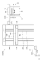
- FIG. 2 is a front view of the first lifting section of the carriage lifting device.
- FIG. 3 is a front view of the second lifting section of the carriage lifting device.
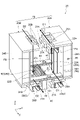
- FIG. 4 is a perspective view of the carriage lifting device in which the maintenance step is in a retracted state.
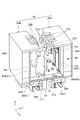
- FIG. 5 is a perspective view of the carriage lifting device in which the maintenance step is advanced.
- FIG. 6 is a block diagram showing the functional configuration of the truck lifting device.
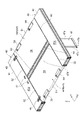
- FIG. 7 is a perspective view showing the maintenance step in the retracted state.
- FIG. 8A is a perspective view when the maintenance step in the retracted state is pulled up.
- FIG. 8(B) is an enlarged perspective view showing the vicinity of the lower end of the side surface of the maintenance step shown in FIG. 8(A).
- FIG. 9A is a perspective view when the maintenance step in the retracted state is pulled up and then rotated.
- FIG. 9(B) is an enlarged perspective view showing the vicinity of the lower end of the side surface of the maintenance step shown in FIG. 9(A).
- FIG. 10A is a perspective view showing one maintenance step in the advanced state.
- FIG. 10B is a perspective view showing an enlarged side portion of the support frame.
- FIG. 11 is a perspective view showing the maintenance step in the advanced state.
- a carriage system 1 shown in FIG. 1 using a carriage lifting device 20 of one embodiment is a system that conveys an article 90 using a carriage 10 that moves along a running rail 5 suspended from a ceiling or the like.
- Examples of the article 90 include containers such as a FOUP (Front Opening Unified Pod) that stores a plurality of semiconductor wafers, a reticle pod that stores glass substrates, and general parts.
- the carriage system 1 includes traveling rails (laying rails) 5A that form a plurality of intrabays 3A in which equipment for processing articles 90, etc. are arranged, and traveling rails that form an interbay 3B that connects the plurality of intrabays 3A. 5B and.
- the travel rail 5A that constitutes the intrabay 3A of this embodiment is laid at a position higher than the travel rail 5B that constitutes the interbay 3B.
- the carriage lifting device 20 of this embodiment is provided at the end of the travel rail 5A that constitutes the intrabay 3A, and moves the carriage 10 between the travel rail 5A and the travel rail 5B. It is relayed by the second elevating rail 21B (see FIGS. 2 to 4).
- the X direction, Y direction and Z direction that are orthogonal to each other are set in the drawings other than FIG.
- the X direction is the extending direction of the running rail 5A, the running rail 5B, the first elevating rail 21A and the second elevating rail 21B
- the Y direction is the arrangement direction of the running rail 5A (conveyance carriage).
- the Z direction is the lifting direction of the first lifting rail 21A and the second lifting rail 21B
- the Z direction is also the vertical direction.
- the carriage 10 that is lifted and lowered by such a carriage lifting device 20 will be described.
- the carriage 10 has a travel drive section 13, a horizontal drive section 14, a rotation drive section 15, an elevation drive section 17, an elevation device 18, and a holding device 19. ing.
- the travel drive unit 13 moves the carriage 10 along the travel rails 5 .
- the travel drive unit 13 is arranged in the space formed by the travel rails 5 .
- the travel drive unit 13 drives rollers (not shown) that travel on the travel rail 5 .
- a horizontal drive section 14 is connected to the lower portion of the travel drive section 13 via a shaft 13A.
- the horizontal driving unit 14 moves the rotation driving unit 15, the lifting driving unit 17, and the lifting device 18 in a direction (Y direction) perpendicular to the extending direction (X direction) of the running rail 5 within a horizontal plane.
- the rotation drive section 15 rotates the elevation drive section 17 and the elevation device 18 in a horizontal plane.
- the elevation drive unit 17 raises and lowers the elevation device 18 by winding up and extending the four belts.
- the lifting device 18 is provided so as to be able to be lifted and lowered by the lifting drive unit 17 and functions as a lifting platform for the carriage 10 .
- a holding device 19 holds an article 90 .
- the carriage lifting device 20 of the carriage 10 is arranged at the end of two running rails 5A, 5A which are arranged in parallel with each other in the same plane and are laid in a state of being suspended from the ceiling.
- the carriage is raised and lowered by raising and lowering 21A and the second raising and lowering rails 21B.
- the carriage lifting device 20 includes a first lifting device 20A, a second lifting device 20B, a pair of support frames 40, 40, and two maintenance steps 50, 50 (second A first maintenance step 50A and a second maintenance step 50B), a stopper 60 (see FIG. 7), and a controller (control section) 80 are provided.
- the first lifting device 20A includes a first lifting rail 21A, a first lifting portion 22A, a first body portion 24A, a first lifting drive portion 25A, and a first stopper unit 27A. ,have.
- the first elevating rail 21A is one rail provided corresponding to each of the two running rails 5A, 5A.
- the first elevating rail 21A moves vertically between the end of the running rail 5A and the end of the running rail 5B spaced vertically and horizontally from the running rail 5A.
- the first elevating rail 21A has a position where the first elevating rail 21A is connected to the traveling rail 5A (that is, a position where the carriage 10 can travel between the traveling rail 5A and the first elevating rail 21A), and a first elevation rail 21A.
- the rail 21A is provided movably between a position where the rail 21A is connected to the travel rail 5B (that is, a position where the carriage 10 can move between the travel rail 5B and the first elevating rail 21A).
- the first elevating rail 21A is fixed to the first elevating section 22A.
- the first elevating section 22A is attached to the first body section 24A extending in the vertical direction via a linear guide 23A. 22 A of 1st raising/lowering parts are provided so that the movement to a perpendicular direction is possible with respect to 24 A of 1st main-body parts.
- the first body portion 24A supports the first lifting portion 22A and the first lifting drive portion 25A.
- the first body portion 24A has a first surface FA perpendicular to the arrangement direction (Y direction) of the two running rails 5A, 5A, and moves the first elevating rail 21A in the elevating direction along the first surface FA. Support possible.
- the first body portion 24A houses a controller 80, which will be described in detail later, and also has an emergency stop button 85 and the like.
- the first elevation drive section 25A is supported by the first body section 24A.
- the first elevation driving section 25A vertically moves the first elevation rail 21A by moving the first elevation section 22A along the first body section 24A (hereinafter simply referred to as "first elevation driving section 25A"). raises and lowers the first elevating rail 21A.”).
- An example of the first elevation drive unit 25A is a servomotor.
- the driving force of the first elevation driving section 25A is transmitted to the first elevation section 22A via the timing belt 26A.
- the encoder is provided in 25 A of 1st raising/lowering drive parts. The encoder can detect states such as the amount of rotation, rotation speed, and rotation direction of the servomotor, for example.
- the driving of the first elevation drive unit 25A is controlled by the controller 80 .
- the first stopper unit 27A is provided at the end of the running rail 5A, the end of the running rail 5B, and the both ends of the first elevating rail 21A.
- the first stopper unit 27A includes a stopper, a stopper drive section, a housing, and the like.
- the first stopper unit 27A is connected when the end of the travel rail 5A and one end of the first elevating rail 21A are not in a connected state (the state in which the carriage 10 can move), and when the end of the travel rail 5B and the first elevating rail 21A are not connected.
- the other end of the rail 21A is not in a connected state, the travel of the carriage 10 is restricted. This prevents the carriage 10 from falling from the end of the travel rail 5A, the end of the travel rail 5B, and the both instead of the first elevating rail 21A.
- the second lifting device 20B includes a second lifting rail 21B, a second lifting portion 22B, a second body portion 24B, a second lifting driving portion 25B, and a second stopper unit 27B.
- the second elevating rail 21B is the other rail provided corresponding to each of the two running rails 5A, 5A.
- the controller 80 and the emergency stop button 85 provided on the first body portion 24A of the first lifting device 20A are not provided on the second body portion 24B of the second lifting device 20B. Except for this, the configuration of the second lifting device 20B matches the configuration of the first lifting device 20A.
- each of the functional configurations of the second lifting rail 21B, the second lifting section 22B, the linear guide 23B, the second body section 24B, the second surface FB, the second lifting drive section 25B, the timing belt 26B, and the second stopper unit 27B. is common to the functional configuration of the first elevating rail 21A, the first elevating section 22A, the linear guide 23A, the first body section 24A, the first surface FA, the first elevating drive section 25A, the timing belt 26A, and the first stopper unit 27A. Therefore, detailed description of the configuration of the second lifting device 20B is omitted.
- the first lifting device 20A moves the carriage 10 traveling in one direction (D1 direction) on the traveling rail 5B to the first lifting rail 21A as shown in FIG.
- This is a lifting device exclusively for going up that moves upward to the connection position with the rail 5A.
- the second lifting device 20B moves the carriage 10 traveling in one direction (D2 direction) on the traveling rail 5A to the second lifting rail 21B as shown in FIG. , to the connecting position with the running rail 5B.
- the pair of support frames 40, 40 span the first body portion 24A and the second body portion 24B.
- the pair of support frames 40, 40 are placed on the overhanging portion 28A provided on the first main body portion 24A and the overhanging portion 28B provided on the second main body portion 24B, thereby forming the first main body portion 24A and the second main body portion 24B. It is spanned over the two main body portions 24B.
- a maintenance step 50 having a boarding surface 54 on which a worker can board is mounted on the pair of support frames 40 , 40 .
- a pair of support frames 40, 40 are provided in an elevating space S1 in which the first elevating rail 21A elevates and the second elevating rail 21B elevates in the extending direction (X direction) of the first elevating rail 21A and the second elevating rail 21B. They are arranged so as to sandwich the elevating space S2. In other words, the pair of support frames 40, 40 do not hinder the elevation of the carriage 10 by the first elevating rails 21A and the elevation of the carriage 10 by the second elevating rails 21B.
- the support frame 40 includes a flat plate portion 41, a mounting portion 43, a locking portion 45, an accommodating portion 47, a stopper 60, and switches (detecting portions) 70 and 70. and have
- the flat plate portion 41 is a flat plate-like member having a placement surface 41a on which an operator can ride.
- the mounting portion 43 is a portion on which the maintenance step 50 is mounted, and a plurality of (eg, four) mounting portions 43 are formed on the side portion 41 b of the flat plate portion 41 .
- the mounting portion 43 is formed with a mounting surface 43a (see FIG. 10B) for supporting the maintenance step 50. As shown in FIG.
- the maintenance step 50 is stretched over the support frame 40 by being placed on the placement portion 43 .
- the locking part 45 is provided so as to be able to advance in the X direction so as to come into contact with the boarding surface 54 of the maintenance step 50 when the maintenance step 50 is placed on the support frame 40 (see FIG. 11). That is, the locking portion 45 locks the maintenance step 50 from above. The locking portion 45 prevents the maintenance step 50 from being lifted upward in the lifting direction of the first lifting rail 21A and the second lifting rail 21B.
- the storage unit 47 stores two maintenance steps 50, 50 (first maintenance step 50A and second maintenance step 50B) in the retracted state.
- the retracted state in the maintenance step 50 will be detailed later.
- the housing portion 47 has a side portion 47a, a bottom portion 47b, a guide portion 47c, and a partition portion 47d.
- the side portion 47a is formed so as to face the side end portion 52 of the maintenance step 50 in the retracted state.
- the bottom surface portion 47b is formed to face the lower end portion 53 of the maintenance step 50 in the retracted state.
- the bottom portion 47b supports the lower end portion 53 of the maintenance step 50 in the retracted state.
- the guide portion 47c is formed to face the bottom surface 55 of the maintenance step 50 in the retracted state.
- the guide portion 47c guides the bottom surface 55 of the maintenance step 50 movable from the advanced state to the retracted state and the bottom surface 55 of the maintenance step 50 movable from the retracted state to the advanced state.
- the partition portion 47d is spanned between the pair of support frames 40,40.
- the partition part 47d is arranged at a position sandwiched between the two maintenance steps 50, 50 (the first maintenance step 50A and the second maintenance step 50B) in the retracted state.
- the stopper 60 is detachably provided with respect to the support frame 40 .
- a stopper 60 is attached to the support frame 40 to maintain the maintenance step 50 in the retracted state.
- the stopper 60 has a flat plate portion 61 , a restricting portion 63 and a projecting portion 65 .
- the flat plate portion 61 is formed in a rectangular shape when viewed from above. When attached to the support frame 40, the flat plate portion 61 covers the flat plate portion 41 of the support frame 40 and part of the upper end portion 51 of the maintenance step 50 in the retracted state.
- the stopper 60 is fixed to the support frame 40 by screws 67 inserted into screw holes provided in the flat plate portion 61 .
- the protruding portion 65 is formed on the rear surface of the flat plate portion 61, and contacts the switches 70, 70 so that the switches 70, 70 are turned on in the above-described mounting state.
- the switches 70, 70 detect whether or not the stopper 60 is attached to the support frame 40.
- the switches 70 , 70 are contact switches, for example, and are provided so as to be contactable by the projecting portion 65 of the stopper 60 as described above.
- a controller 80 acquires the detection result of the stopper 60 by the switches 70 , 70 .
- the maintenance step 50 includes a retracted state (see FIG. 4) in which the boarding surface 54 is evacuated from the elevation spaces S1 and S2 by setting the boarding surface 54 to a standing posture perpendicular to the Y direction (arrangement direction), ) in which it is placed on the support frame 40 so as to intersect perpendicularly with ), and an advanced state (see FIG. 5) in which it advances into the elevating spaces S1 and S2.
- the maintenance step 50 includes a first maintenance step 50A provided to advance into the lifting space S1 of the first lifting rail 21A and a second maintenance step 50A provided to advance to the lifting space S2 of the second lifting rail 21B. and a maintenance step 50B.
- the first maintenance step 50A and the second maintenance step 50B are arranged in the central portion between the first main body portion 24A and the second main body portion 24B in the retracted state.
- the first maintenance step 50A and the second maintenance step 50B are collectively referred to as the maintenance step 50.
- FIG. 1 the first maintenance step 50A and the second maintenance step 50B are collectively referred to as the maintenance step 50.
- the maintenance step 50 includes an upper end portion 51 that becomes an upper end portion, side end portions 52 and 52 that become side end portions, and a lower end portion that becomes a lower end portion in the retracted state. It has a portion 53 , a boarding surface 54 on which a worker rides in the advanced state, a bottom surface 55 opposite to the boarding surface 54 , and a handle 59 .
- a reinforcement portion 55A is arranged on the bottom surface 55 at a portion that contacts when the maintenance step 50 is placed on the support frame 40 .
- the reinforcing portion 55A is a plate-like member extending along the side end portion 52.
- the handle 59 is provided on the upper end portion 51, and the attachment portion to the upper end portion 51 is provided so as to be rotatable. This makes it easier for the operator to hold the maintenance step 50 in any rotational state.
- the side ends 52, 52 are formed with grooves 52a.
- the groove portion 52a is provided so as to be engaged with pins 49A and 49B provided on the side surface portion 41b of the support frame 40 via a flat plate 49.
- the maintenance step 50 is supported at its upper end 51 by the pins 49A and 49B provided on the support frame 40 in the retracted state, and is slidable in the Z direction with respect to the support frame 40 in the upright posture. is provided.
- the maintenance step 50 is rotatably provided so that when the lower end portion 53 is slid to the position of the support frame 40, the maintenance step 50 is in the advanced state (see FIG. 4).
- the controller 80 shown in FIGS. 2 and 6 controls each part of the carriage lifting device 20 .
- the controller 80 is provided in the first main body portion 24A of the carriage lifting device 20 .
- the controller 80 has a CPU (Central Processing Unit), RAM (Random Access Memory), ROM (Read Only Memory), and the like.
- hardware such as a CPU, RAM, and ROM cooperate with software such as programs to perform various controls.
- the controller 80 restricts the driving of the first elevation drive section 25A and the second elevation drive section 25B when the switches 70, 70 detect that the stopper 60 is not attached. More specifically, when the stopper 60 is removed from the support frame 40 and the projecting portion 65 of the stopper 60 is not in contact with the switches 70, 70, the first elevation drive section 25A and the second elevation drive section 25B are driven. prohibited.
- the operator mounts the support frame 40 of the truck lift 20 using, for example, a ladder or a passage accessible to the truck lift 20 .
- a worker removes the stopper 60 fixed to the support frame 40 by the screw 67 . This makes it possible to move the maintenance step 50 upward.
- the operator grasps the handle 59 of the maintenance step 50 in the retracted state shown in FIG. 7, and lifts the maintenance step 50 upward as shown in FIG. 8(A).
- the operator slides the maintenance step 50 upward until the lower end of the groove 52a is locked by the pin 49A.
- the operator rotates the maintenance step 50 to contact and support the mounting surface 43a of the mounting section 43 shown in FIG. 10(B).
- the maintenance step 50 can be set to the advance state.
- the operator holds the handle 59 of the maintenance step 50 shown in FIG.
- the maintenance step 50 is rotated so that the As shown in FIG. 8A, the operator puts the maintenance step 50 in an upright state, moves the maintenance step 50 downward along the storage portion 47, and stores it in the storage portion 47 as shown in FIG.
- a cushioning material (not shown) serving as a cushion is provided at a portion of the accommodation portion 47 that is in contact with the maintenance step 50 .
- the carriage lifting device 20 of the above-described embodiment is provided with a pair of support frames 40, 40 over which a maintenance step 50 on which an operator can ride is suspended. Further, since the pair of support frames 40, 40 are arranged so as to sandwich the elevating spaces S1, S2, they do not hinder the elevation of the first elevating rail 21A and the second elevating rail 21B. As a result, maintenance work can be performed simply by placing the maintenance step 50 on the support frame 40 . In addition, the operator can perform maintenance work by getting on the maintenance step 50 without getting on the lift of the vehicle for work at height. Thereby, workability can be improved. Furthermore, in the carriage lifting device 20 having this configuration, there is no need to secure an entry space for the lift of the high lift work vehicle in the carriage lifting device 20 . As a result, the overall size of the carriage system including the carriage lifting device 20 can be made compact.
- the maintenance step 50 of the above-described embodiment consists of a retracted state in which the boarding surface 54 is in a standing posture perpendicular to the Y direction (arrangement direction) and is retracted from the elevation spaces S1 and S2, and a state in which the boarding surface 54 is perpendicular to the ascending/descending direction. , and an advanced state in which it advances into the elevating spaces S1 and S2 by being placed on the support frame 40, and is provided so as to be movable between the advanced state.
- an advanced state in which it advances into the elevating spaces S1 and S2 by being placed on the support frame 40, and is provided so as to be movable between the advanced state.
- the maintenance step 50 of the above-described embodiment is supported by the support frame 40 at its upper end 51, and is vertically slidable with respect to the support frame 40 in an upright posture. It is rotatably provided so that when its lower end portion 53 is slid to the support frame 40, it will be in the advanced state as shown in FIG.
- the maintenance step 50 having such a configuration, the operator can shift from the retracted state to the advanced state by a simple operation of pulling the maintenance step 50 upward and then tilting it toward the support frame 40 .
- the first maintenance step 50A and the second maintenance step 50B of the above embodiment are arranged in the central portion between the first main body portion 24A and the second main body portion 24B in the retracted state.
- the maintenance step 50 which is arranged in a standing posture between the first body portion 24A and the second body portion 24B, moves up and down the first lifting rail 21A as shown in FIGS. It becomes a wall that partitions the space S1 and the elevating space S2 of the second elevating rail 21B.
- the carriage lifting device 20 of the above embodiment includes a stopper 60 attached to the support frame 40 to maintain the maintenance step 50 in the retracted state, and a stopper for the support frame 40. and switches 70, 70 for detecting whether or not 60 is attached.
- the controller 80 restricts the driving of the first elevation driving section 25A and the second elevation driving section 25B when the switches 70, 70 detect that the stopper 60 is not attached.
- the stopper 60 is removed by the operator, that is, when there is a high possibility that the operator is performing maintenance work on the carriage lifting device 20, the first lifting drive section 25A is moved to the first lifting rail. 21A and the second lifting drive section 25B are prohibited from lifting the second lifting rail 21B, the safety of the operator can be ensured.
- a locking portion 45 for locking the maintenance step 50 on the boarding surface 54 side is provided. This prevents the maintenance step 50 from rising from the support frame 40 even if some force acts on the maintenance step 50 from below, thereby ensuring the safety of the operator.
- the carriages 10, 10 traveling on the two traveling rails 5A, 5A and the traveling rails 5B, 5B arranged in the same plane travel in opposite directions.
- the first lifting section 22A is used exclusively for going up
- the second lifting section 22B is used as a lifting device exclusively for going down
- the present invention is not limited to this.
- the carriages 10, 10 running on the two running rails 5A, 5A and the running rails 5B, 5B arranged in the same plane run in the same direction, and the first lifting part 22A and the second lifting part 22A
- the section 22B may be used exclusively for uplink or downlink.
- the controller 80 is provided in the first main body portion 24A. You may make it connect so that communication may be carried out by a cable or radio
- the first maintenance step 50A and the second maintenance step 50B in the retracted state are arranged in a standing posture between the first main body portion 24A and the second main body portion 24B.
- the present invention is not limited to this.
- the first maintenance step 50A may be retracted along the first main body portion 24A
- the second maintenance step 50B may be retracted along the second main body portion 24B.
Landscapes
- Engineering & Computer Science (AREA)
- Mechanical Engineering (AREA)
- Structural Engineering (AREA)
- Automation & Control Theory (AREA)
- Architecture (AREA)
- Civil Engineering (AREA)
- Transportation (AREA)
- Warehouses Or Storage Devices (AREA)
- Forklifts And Lifting Vehicles (AREA)
- Handcart (AREA)
Abstract
Description
Claims (6)
- 天井に吊り下げられた状態で同一平面内において平行に敷設される二本の敷設レールのそれぞれに対応して昇降可能に設けられる、第一昇降レール及び第二昇降レールと、
前記第一昇降レールを昇降させる第一昇降駆動部と、
前記第二昇降レールを昇降させる第二昇降駆動部と、
前記二本の敷設レールの配列方向に直交する第一面を有し、前記第一面に沿って前記第一昇降レールを昇降方向に移動可能に支持する第一本体部と、
前記第一面に対して前記配列方向に対向する第二面を有し、前記第二面に沿って前記第二昇降レールを昇降方向に移動可能に支持する第二本体部と、
前記第一本体部及び前記第二本体部に掛け渡されると共に、作業者が搭乗可能な搭乗面を有するメンテナンスステップが掛け渡される一対の支持フレームと、を備え、
一対の前記支持フレームは、前記第一昇降レール及び前記第二昇降レールの延在方向において、前記第一昇降レール及び前記第二昇降レールが昇降する昇降空間を挟むように配置されている、台車昇降装置。 - 前記搭乗面を前記配列方向に直交する起立姿勢にすることで前記昇降空間から退避させる退避状態と、前記搭乗面が前記昇降方向と直交するように前記支持フレームに前記搭乗面を載置することで前記昇降空間に進出させる進出状態と、の間で可動可能に設けられている、前記メンテナンスステップを更に備える、請求項1記載の台車昇降装置。
- 前記メンテナンスステップは、前記退避状態においてその上端部が前記支持フレームに支持されると共に、前記起立姿勢で前記支持フレームに対して前記昇降方向にスライド可能に設けられており、その下端部を前記支持フレームにまでスライドさせたときに、前記進出状態となるように回動可能に設けられている、請求項2記載の台車昇降装置。
- 前記メンテナンスステップは、前記進出状態において、
前記第一昇降レールの昇降空間に進出するように設けられる第一メンテナンスステップと、
前記第二昇降レールの昇降空間に進出するように設けられる第二メンテナンスステップと、を有し、
前記第一メンテナンスステップ及び前記第二メンテナンスステップは、前記退避状態において、前記第一本体部と前記第二本体部との間の中央部に配置されている、請求項3記載の台車昇降装置。 - 前記第一昇降駆動部及び前記第二昇降駆動部を制御する制御部と、
前記メンテナンスステップを前記退避状態に維持するために前記支持フレームに取り付けられるストッパと、
前記支持フレームに対する前記ストッパの取り付けの有無を検知する検知部と、を更に備え、
前記制御部は、前記検知部によって前記ストッパが取り付けられていないことを検知しているときに、前記第一昇降駆動部及び前記第二昇降駆動部が駆動することを規制する、請求項2~4の何れか一項記載の台車昇降装置。 - 前記支持フレームには、前記進出状態にある前記メンテナンスステップの前記搭乗面を係止する係止部が設けられている、請求項2~5の何れか一項記載の台車昇降装置。
Priority Applications (3)
| Application Number | Priority Date | Filing Date | Title |
|---|---|---|---|
| US18/285,322 US20240182265A1 (en) | 2021-04-07 | 2022-02-09 | Carriage lifting/lowering device |
| CN202280019849.6A CN116963974A (zh) | 2021-04-07 | 2022-02-09 | 台车升降装置 |
| JP2023512838A JP7485208B2 (ja) | 2021-04-07 | 2022-02-09 | 台車昇降装置 |
Applications Claiming Priority (2)
| Application Number | Priority Date | Filing Date | Title |
|---|---|---|---|
| JP2021-065363 | 2021-04-07 | ||
| JP2021065363 | 2021-04-07 |
Publications (1)
| Publication Number | Publication Date |
|---|---|
| WO2022215345A1 true WO2022215345A1 (ja) | 2022-10-13 |
Family
ID=83546301
Family Applications (1)
| Application Number | Title | Priority Date | Filing Date |
|---|---|---|---|
| PCT/JP2022/005178 Ceased WO2022215345A1 (ja) | 2021-04-07 | 2022-02-09 | 台車昇降装置 |
Country Status (5)
| Country | Link |
|---|---|
| US (1) | US20240182265A1 (ja) |
| JP (1) | JP7485208B2 (ja) |
| CN (1) | CN116963974A (ja) |
| TW (1) | TWI868440B (ja) |
| WO (1) | WO2022215345A1 (ja) |
Cited By (1)
| Publication number | Priority date | Publication date | Assignee | Title |
|---|---|---|---|---|
| KR20240156946A (ko) | 2023-04-24 | 2024-10-31 | 가부시키가이샤 다이후쿠 | 승강 장치 |
Citations (4)
| Publication number | Priority date | Publication date | Assignee | Title |
|---|---|---|---|---|
| JPH1018578A (ja) * | 1996-07-05 | 1998-01-20 | Kawada Kogyo Kk | 部分作業足場とこれを用いたジョイント足場の架設方法 |
| JP2002370807A (ja) * | 2001-06-11 | 2002-12-24 | Shinko Electric Co Ltd | 高層収納棚 |
| JP2009073624A (ja) * | 2007-09-20 | 2009-04-09 | Daifuku Co Ltd | 物品収納設備 |
| JP2019214438A (ja) * | 2018-06-11 | 2019-12-19 | 村田機械株式会社 | 搬送車の走行設備 |
Family Cites Families (6)
| Publication number | Priority date | Publication date | Assignee | Title |
|---|---|---|---|---|
| JP2913618B2 (ja) * | 1996-08-01 | 1999-06-28 | 川崎重工業株式会社 | 補助レール付台車装置 |
| JP2006066723A (ja) * | 2004-08-27 | 2006-03-09 | Murata Mach Ltd | 搬送車システム |
| JP5429559B2 (ja) * | 2010-02-01 | 2014-02-26 | 株式会社ダイフク | 倉庫設備 |
| TWI447058B (zh) * | 2011-11-30 | 2014-08-01 | 華亞科技股份有限公司 | 天車輸送系統及其運轉方法 |
| JP5713203B2 (ja) * | 2012-03-27 | 2015-05-07 | 株式会社ダイフク | 物品収納設備 |
| JP6443264B2 (ja) * | 2015-08-12 | 2018-12-26 | 株式会社ダイフク | 物品収納設備 |
-
2022
- 2022-02-09 US US18/285,322 patent/US20240182265A1/en active Pending
- 2022-02-09 CN CN202280019849.6A patent/CN116963974A/zh active Pending
- 2022-02-09 JP JP2023512838A patent/JP7485208B2/ja active Active
- 2022-02-09 WO PCT/JP2022/005178 patent/WO2022215345A1/ja not_active Ceased
- 2022-04-01 TW TW111112720A patent/TWI868440B/zh active
Patent Citations (4)
| Publication number | Priority date | Publication date | Assignee | Title |
|---|---|---|---|---|
| JPH1018578A (ja) * | 1996-07-05 | 1998-01-20 | Kawada Kogyo Kk | 部分作業足場とこれを用いたジョイント足場の架設方法 |
| JP2002370807A (ja) * | 2001-06-11 | 2002-12-24 | Shinko Electric Co Ltd | 高層収納棚 |
| JP2009073624A (ja) * | 2007-09-20 | 2009-04-09 | Daifuku Co Ltd | 物品収納設備 |
| JP2019214438A (ja) * | 2018-06-11 | 2019-12-19 | 村田機械株式会社 | 搬送車の走行設備 |
Cited By (1)
| Publication number | Priority date | Publication date | Assignee | Title |
|---|---|---|---|---|
| KR20240156946A (ko) | 2023-04-24 | 2024-10-31 | 가부시키가이샤 다이후쿠 | 승강 장치 |
Also Published As
| Publication number | Publication date |
|---|---|
| TWI868440B (zh) | 2025-01-01 |
| JPWO2022215345A1 (ja) | 2022-10-13 |
| TW202246148A (zh) | 2022-12-01 |
| CN116963974A (zh) | 2023-10-27 |
| US20240182265A1 (en) | 2024-06-06 |
| JP7485208B2 (ja) | 2024-05-16 |
Similar Documents
| Publication | Publication Date | Title |
|---|---|---|
| KR102276842B1 (ko) | 층간 반송 설비 | |
| KR102073777B1 (ko) | 물품 수납 설비 | |
| EP3159922B1 (en) | Carrier transport system and transport method | |
| KR102397716B1 (ko) | 물품 반송 장치 | |
| KR102700083B1 (ko) | 그리퍼 장치, 반송차, 및 반송 방법 | |
| KR20120055493A (ko) | 기판 컨테이너 보관 시스템 | |
| WO2019061773A1 (zh) | 回流线体及具有该回流线体的锁螺丝平台 | |
| KR102700084B1 (ko) | 그리퍼 장치, 반송차, 및 반송 방법 | |
| KR20120050931A (ko) | 기판 컨테이너 보관 시스템과 연결하기 위한 일체형 시스템 | |
| CN105584768A (zh) | 物品搬送车 | |
| JP2016003069A (ja) | コンテナ昇降搬送装置 | |
| WO2022215345A1 (ja) | 台車昇降装置 | |
| TWI836071B (zh) | 貯藏庫系統 | |
| CN116605602A (zh) | 保管架及搬送车系统 | |
| JP2023097422A (ja) | 移送装置及び移送方法 | |
| JP4929535B2 (ja) | 高層収納棚 | |
| KR102801572B1 (ko) | 물품 반송 설비 | |
| TW202442571A (zh) | 保管系統 | |
| JP7070522B2 (ja) | ストッカ | |
| KR102761419B1 (ko) | 물품 반송 설비 | |
| CN211847001U (zh) | 一种双电机升降机械伸展装置 | |
| KR102624073B1 (ko) | 반도체 웨이퍼 캐리어 운송용 oht의 카트 적재 시스템 | |
| KR20260021191A (ko) | 물류 이송 설비 및 천정형 보관 장치 | |
| JP2025140604A (ja) | 搬送車 | |
| KR102844484B1 (ko) | 여러 타입의 웨이퍼카세트 혼용이 가능한 로드포트모듈 |
Legal Events
| Date | Code | Title | Description |
|---|---|---|---|
| 121 | Ep: the epo has been informed by wipo that ep was designated in this application |
Ref document number: 22784330 Country of ref document: EP Kind code of ref document: A1 |
|
| WWE | Wipo information: entry into national phase |
Ref document number: 2023512838 Country of ref document: JP |
|
| WWE | Wipo information: entry into national phase |
Ref document number: 202280019849.6 Country of ref document: CN |
|
| WWE | Wipo information: entry into national phase |
Ref document number: 18285322 Country of ref document: US |
|
| WWE | Wipo information: entry into national phase |
Ref document number: 11202306651Q Country of ref document: SG |
|
| NENP | Non-entry into the national phase |
Ref country code: DE |
|
| 122 | Ep: pct application non-entry in european phase |
Ref document number: 22784330 Country of ref document: EP Kind code of ref document: A1 |
|
| WWG | Wipo information: grant in national office |
Ref document number: 11202306651Q Country of ref document: SG |
|
| WWP | Wipo information: published in national office |
Ref document number: 11202306651Q Country of ref document: SG |