WO2022215212A1 - 荷電粒子線装置および試料の解析方法 - Google Patents
荷電粒子線装置および試料の解析方法 Download PDFInfo
- Publication number
- WO2022215212A1 WO2022215212A1 PCT/JP2021/014821 JP2021014821W WO2022215212A1 WO 2022215212 A1 WO2022215212 A1 WO 2022215212A1 JP 2021014821 W JP2021014821 W JP 2021014821W WO 2022215212 A1 WO2022215212 A1 WO 2022215212A1
- Authority
- WO
- WIPO (PCT)
- Prior art keywords
- charged particle
- sample
- valve
- particle beam
- pretreatment chamber
- Prior art date
- Legal status (The legal status is an assumption and is not a legal conclusion. Google has not performed a legal analysis and makes no representation as to the accuracy of the status listed.)
- Ceased
Links
Images


Classifications
-
- H—ELECTRICITY
- H01—ELECTRIC ELEMENTS
- H01J—ELECTRIC DISCHARGE TUBES OR DISCHARGE LAMPS
- H01J37/00—Discharge tubes with provision for introducing objects or material to be exposed to the discharge, e.g. for the purpose of examination or processing thereof
- H01J37/02—Details
- H01J37/18—Vacuum locks ; Means for obtaining or maintaining the desired pressure within the vessel
- H01J37/185—Means for transferring objects between different enclosures of different pressure or atmosphere
-
- H—ELECTRICITY
- H01—ELECTRIC ELEMENTS
- H01J—ELECTRIC DISCHARGE TUBES OR DISCHARGE LAMPS
- H01J37/00—Discharge tubes with provision for introducing objects or material to be exposed to the discharge, e.g. for the purpose of examination or processing thereof
- H01J37/02—Details
- H01J37/18—Vacuum locks ; Means for obtaining or maintaining the desired pressure within the vessel
-
- H—ELECTRICITY
- H01—ELECTRIC ELEMENTS
- H01J—ELECTRIC DISCHARGE TUBES OR DISCHARGE LAMPS
- H01J37/00—Discharge tubes with provision for introducing objects or material to be exposed to the discharge, e.g. for the purpose of examination or processing thereof
- H01J37/30—Electron-beam or ion-beam tubes for localised treatment of objects
- H01J37/31—Electron-beam or ion-beam tubes for localised treatment of objects for cutting or drilling
-
- H—ELECTRICITY
- H01—ELECTRIC ELEMENTS
- H01J—ELECTRIC DISCHARGE TUBES OR DISCHARGE LAMPS
- H01J37/00—Discharge tubes with provision for introducing objects or material to be exposed to the discharge, e.g. for the purpose of examination or processing thereof
- H01J37/02—Details
- H01J37/16—Vessels; Containers
-
- H—ELECTRICITY
- H01—ELECTRIC ELEMENTS
- H01J—ELECTRIC DISCHARGE TUBES OR DISCHARGE LAMPS
- H01J37/00—Discharge tubes with provision for introducing objects or material to be exposed to the discharge, e.g. for the purpose of examination or processing thereof
- H01J37/26—Electron or ion microscopes; Electron or ion diffraction tubes
- H01J37/261—Details
-
- H—ELECTRICITY
- H01—ELECTRIC ELEMENTS
- H01J—ELECTRIC DISCHARGE TUBES OR DISCHARGE LAMPS
- H01J37/00—Discharge tubes with provision for introducing objects or material to be exposed to the discharge, e.g. for the purpose of examination or processing thereof
- H01J37/26—Electron or ion microscopes; Electron or ion diffraction tubes
- H01J37/28—Electron or ion microscopes; Electron or ion diffraction tubes with scanning beams
-
- H—ELECTRICITY
- H01—ELECTRIC ELEMENTS
- H01J—ELECTRIC DISCHARGE TUBES OR DISCHARGE LAMPS
- H01J37/00—Discharge tubes with provision for introducing objects or material to be exposed to the discharge, e.g. for the purpose of examination or processing thereof
- H01J37/30—Electron-beam or ion-beam tubes for localised treatment of objects
- H01J37/305—Electron-beam or ion-beam tubes for localised treatment of objects for casting, melting, evaporating, or etching
-
- H—ELECTRICITY
- H01—ELECTRIC ELEMENTS
- H01J—ELECTRIC DISCHARGE TUBES OR DISCHARGE LAMPS
- H01J2237/00—Discharge tubes exposing object to beam, e.g. for analysis treatment, etching, imaging
- H01J2237/18—Vacuum control means
- H01J2237/182—Obtaining or maintaining desired pressure
-
- H—ELECTRICITY
- H01—ELECTRIC ELEMENTS
- H01J—ELECTRIC DISCHARGE TUBES OR DISCHARGE LAMPS
- H01J2237/00—Discharge tubes exposing object to beam, e.g. for analysis treatment, etching, imaging
- H01J2237/18—Vacuum control means
- H01J2237/184—Vacuum locks
-
- H—ELECTRICITY
- H01—ELECTRIC ELEMENTS
- H01J—ELECTRIC DISCHARGE TUBES OR DISCHARGE LAMPS
- H01J2237/00—Discharge tubes exposing object to beam, e.g. for analysis treatment, etching, imaging
- H01J2237/26—Electron or ion microscopes
- H01J2237/28—Scanning microscopes
-
- H—ELECTRICITY
- H01—ELECTRIC ELEMENTS
- H01J—ELECTRIC DISCHARGE TUBES OR DISCHARGE LAMPS
- H01J2237/00—Discharge tubes exposing object to beam, e.g. for analysis treatment, etching, imaging
- H01J2237/30—Electron or ion beam tubes for processing objects
- H01J2237/317—Processing objects on a microscale
-
- H—ELECTRICITY
- H01—ELECTRIC ELEMENTS
- H01J—ELECTRIC DISCHARGE TUBES OR DISCHARGE LAMPS
- H01J2237/00—Discharge tubes exposing object to beam, e.g. for analysis treatment, etching, imaging
- H01J2237/30—Electron or ion beam tubes for processing objects
- H01J2237/317—Processing objects on a microscale
- H01J2237/31749—Focused ion beam
Definitions
- the present invention relates to a charged particle beam device and a sample analysis method, and more particularly to a charged particle beam device provided with an observation chamber and a pretreatment chamber, and a sample analysis method using the charged particle beam device.
- planar sample preparation method ion rimming
- the planar milling method is a method of processing a wide range by, for example, obliquely irradiating an argon ion beam to the surface of a sample and eccentrically moving the center of the argon ion beam and the center of rotation of the sample.
- the irradiation angle of the ion beam is made parallel to the processed surface of the sample, it is possible to form a processed surface in which the formation of irregularities due to differences in crystal orientation or compositional etching rate is reduced.
- the irradiation angle of the ion beam is set to be nearly perpendicular to the processing surface of the sample, it is possible to perform processing emphasizing unevenness by utilizing the etching rate difference.
- a pretreatment chamber for ion milling is connected via a valve to an observation chamber of a charged particle beam device.
- a technique is disclosed in which, with the valve closed, the pretreatment chamber is evacuated to a predetermined degree of vacuum by a vacuum pump, and ion milling is performed on the sample.
- Patent Document 2 discloses a charged particle beam apparatus that includes an observation room for SEM observation and a pretreatment room for ion milling connected to the observation room via a valve.
- a vacuum pump equivalent to a rotary pump and a vacuum pump equivalent to a turbomolecular pump are connected in a tandem structure, and two intake ports of the turbomolecular pump are connected to the observation chamber and the pretreatment chamber.
- the process chamber is being evacuated.
- the inventors of the present application when performing pretreatment that requires a high-vacuum environment such as ion milling inside a charged particle beam device, the degree of vacuum required for pretreatment can only be achieved by vacuum evacuation by a roughing pump. was found to be unsatisfactory. Furthermore, in the recent semiconductor market, there is a demand for an improvement in throughput. Therefore, it is necessary to shorten the time required to reach the degree of vacuum required for pretreatment. Therefore, the inventors of the present application separated an observation room for SEM observation and a pretreatment room for ion milling, respectively, and studied a charged particle beam apparatus in which the observation room and the pretreatment room were connected.
- the pretreatment chamber requires a vacuum pump different from the observation chamber for SEM observation. Therefore, it is necessary to install a new vacuum pump, which poses problems such as an increase in installation location, an increase in installation cost, and vibration generated during evacuation.
- Patent Document 2 does not specify a specific sequence for evacuating the observation chamber and the pretreatment chamber, and it may take a long time to evacuate the pretreatment chamber.
- the main purpose of this application is to provide a charged particle beam device that simplifies the connection relationship between the observation chamber, pretreatment chamber, and vacuum pump.
- Another object of the present invention is to provide an analytical method (analytical means) capable of evacuating the pretreatment chamber in a short period of time using such a charged particle beam device.
- a charged particle beam device includes an observation room having a first exhaust port, a first lens barrel attached to the observation room, a first charging chamber provided inside the first lens barrel, and a first charging a first charged particle source that can irradiate a particle beam; a first stage that is provided below the first charged particle source inside the observation chamber and on which a sample holder that holds a sample can be installed; and a gate valve.
- a pretreatment chamber connected to the observation chamber via and having a second exhaust port; a second lens barrel attached to the pretreatment chamber; a second lens barrel provided inside the second lens barrel; a second charged particle source capable of irradiating a second charged particle beam; and a second charged particle source provided below the second charged particle source inside the pretreatment chamber and capable of installing the sample holder holding the sample.
- a first vacuum pump having two stages, a first intake port and a second intake port, a first exhaust pipe connected to the first intake port and the first exhaust port, a second intake port and the first vacuum pump; a second exhaust pipe connected to two exhaust ports; a first valve provided in the middle of the first exhaust pipe; a second valve provided in the middle of the second exhaust pipe; source, the first stage, the second charged particle source, and the second stage, controls the driving of the first vacuum pump, and controls the gate valve, the first valve, and the second stage.
- a controller that controls the opening/closing state of each of the two valves, and analysis means that is executed by the controller when the sample holder holding the sample is placed on the second stage.
- each diameter of the first intake port and the first exhaust port is larger than each diameter of the second intake port and the second exhaust port.
- the analyzing means (a) opens the gate valve, opens the first valve, closes the second valve, and drives the first vacuum pump, thereby (b) closing the gate valve and opening the second valve after step (a); c) after the step (b), irradiating the sample with the second charged particle beam from the second charged particle source while evacuating the pretreatment chamber with the first vacuum pump; and a step of processing the sample.
- a charged particle beam device includes an observation room, a first lens barrel attached to the observation room, and a a first charged particle source, a first stage provided below the first charged particle source inside the observation chamber and on which a sample holder holding a sample can be installed, and the observation chamber via a gate valve and a sample exchange rod provided inside the pretreatment chamber for moving the sample holder between the observation chamber and the pretreatment chamber.
- the pretreatment chamber is composed of a second unit and a third unit which are detachable from each other, the second unit is provided with the gate valve, and the third unit is provided with the sample exchange rod. is provided.
- a sample analysis method includes an observation chamber having a first exhaust port, a first lens barrel attached to the observation chamber, a a first charged particle source that can irradiate a particle beam; a first stage that is provided below the first charged particle source inside the observation chamber and on which a sample holder that holds a sample can be installed; and a gate valve.
- a pretreatment chamber connected to the observation chamber via and having a second exhaust port and a third exhaust port; a second lens barrel attached to the pretreatment chamber; a second charged particle source provided and capable of irradiating a second charged particle beam; and the sample holder provided below the second charged particle source inside the pretreatment chamber and holding the sample.
- a sample exchange rod provided inside the pretreatment chamber for moving the sample holder between the observation chamber and the pretreatment chamber; and a first intake port. and a first vacuum pump having a second inlet, a second vacuum pump having a third inlet and having a lower achievable degree of vacuum than the first vacuum pump, the first inlet and the first
- the sample analysis method comprises (a) placing the sample holder holding the sample on the second stage, (b) closing the gate valve after step (a), By opening the first valve, closing the second valve, opening the third valve, and driving the second vacuum pump, each of the observation chamber and the pretreatment chamber is (c) after step (b), by opening the gate valve, closing the third valve, and driving the first vacuum pump, (d) closing the gate valve after step (c), and closing the second valve; (e) after said step (d), while evacuating said pretreatment chamber by means of said first vacuum pump, said second charged particles are transferred from said second charged particle source to said sample; (f) opening the gate valve after step (e); and (g) exchanging the sample after step (f).
- each diameter of the first intake port and the first exhaust port is larger than each diameter of the second intake port and the second exhaust port.
- a charged particle beam apparatus in which the connection relationship between the observation chamber, the pretreatment chamber, and the vacuum pump is simplified. Moreover, using such a charged particle beam device, it is possible to provide an analysis method (analysis means) capable of evacuating the pretreatment chamber in a short time.
- FIG. 1 is a schematic diagram showing a charged particle beam device according to Embodiment 1.
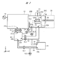
- FIG. FIG. 2 is a schematic diagram of a main part in which a part of the charged particle beam device according to Embodiment 1 is enlarged; 4 is a side view showing the first unit of the pretreatment chamber in Embodiment 1.
- FIG. 1 is a schematic diagram showing a system configuration of a charged particle beam device according to Embodiment 1;
- FIG. 4 is a flow chart showing a sample analysis method (analysis means) in Embodiment 1.
- the X-direction, Y-direction and Z-direction described in this application intersect each other and are orthogonal to each other.
- the Z direction is described as the vertical direction, height direction, or thickness direction of a certain structure.
- Embodiment 1 ⁇ Configuration of charged particle beam device 1> A charged particle beam device 1 according to Embodiment 1 will be described below with reference to FIGS. 1 to 3.
- SEM scanning electron microscope
- the charged particle beam device 1 includes an observation room 10, a lens barrel 11 attached to the observation room 10, a pretreatment chamber 20, and a lens barrel 21 attached to the pretreatment chamber 20. Prepare.
- the charged particle beam device 1 also includes a vacuum gauge 14 for measuring the degree of vacuum inside the observation chamber 10 and a vacuum gauge 24 for measuring the degree of vacuum inside the pretreatment chamber 20 .
- an electron source (charged particle source) 12 capable of emitting an electron beam (charged particle beam) EB, a condenser lens 15 for focusing the electron beam EB, an objective lens 16, and the like are provided inside the lens barrel 11.
- a stage 13 on which a sample holder HL holding the sample SAM can be installed is provided below the electron source 12 inside the observation chamber 10 .
- the lens barrel 11 includes an electron optical system such as a condenser lens 15, an objective lens 16, a polarizing lens and a scanning lens, and a vacuum system for making the inside of the lens barrel 11 high vacuum.
- a pump (equivalent to an ion pump) is provided.
- the observation room 10 is provided with a detector for detecting secondary electrons and the like, and an image processing section for converting a signal of the secondary electrons into image data.
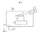
- An ion source (charged particle source) 22 capable of emitting an ion beam (charged particle beam) IB and the like are provided inside the lens barrel 21 .
- a stage 23 is provided below the ion source 22 inside the pretreatment chamber 20 for setting a sample holder HL that holds the sample SAM.
- a sample exchange rod 25 for moving the sample holder HL between the observation chamber 10 and the pretreatment chamber 20 is provided inside the pretreatment chamber 20 .
- the pretreatment chamber 20 is provided with a transfer port 26, and by opening the transfer port 26, the sample SAM is held from the outside to the inside of the pretreatment chamber 20 or from the inside to the outside of the pretreatment chamber 20.
- the sample holder HL can be transported.
- pretreatment by ion milling is performed.
- the sample SAM on the stage 23 is irradiated with an ion beam IB from the ion source 22, and the sample SAM is processed to obtain a milling surface.
- the lens barrel 21 is attached to the pretreatment chamber 20 in a tilted state so that the ion beam IB is tilted with respect to the rotation axis of the sample SAM.
- the stage 23 has at least a rotating mechanism. By irradiating the sample SAM with the ion beam IB while rotating the stage 23, a uniform plane is formed on the sample SAM by ion milling.
- the center of rotation of the sample SAM and the center of the ion beam can be eccentric.
- the processing range is widened, and the degree of freedom in processing can be increased.
- the stage 23 has a movement axis in the Y direction.
- the sample holder HL deviates from the movement axis of the sample exchange rod 25. Therefore, when the sample holder HL is moved from the pretreatment chamber 20 to the observation chamber 10, the eccentric mechanism is initialized. It is necessary to install a safety mechanism that restores the state.
- the observation chamber 10 for SEM observation and the pretreatment chamber 20 for ion milling are separated by the gate valve VL5 for the purpose of improving the throughput for processing and observing the sample SAM. connected through
- FIG. 2 shows the peripheral structure of the observation chamber 10, the pretreatment chamber 20, and each vacuum pump in the charged particle beam device 1 of FIG.
- the charged particle beam device 1 includes a high vacuum pump (vacuum pump) 40 and a roughing pump (vacuum pump) 41 .
- the high-vacuum pump 40 is, for example, a turbo-molecular pump, and has main inlets 31a and 32a.
- the roughing pump 41 is, for example, a dry pump.
- the high vacuum pump 40 can achieve a degree of vacuum of 10 -2 to 10 -5 Pa, for example.
- the degree of vacuum that can be achieved by the roughing pump 41 is lower than that of the high vacuum pump 40, for example several Pa to 100 Pa.
- the exhaust pipe 31 is connected to the intake port 31 a of the high vacuum pump 40 and the exhaust port 31 b of the observation room 10 .
- the exhaust pipe 32 is connected to an intake port 32 a of the high vacuum pump 40 and an exhaust port 32 b of the pretreatment chamber 20 .
- each of the intake port 31a and the exhaust port 31b is larger than the diameter of each of the intake port 32a and the exhaust port 32b. Therefore, the exhaust speed of the exhaust pipe 31 is faster than the exhaust speed of the exhaust pipe 32 . Therefore, when the high vacuum pump 40 is driven, the degree of vacuum in the pretreatment chamber 20 temporarily becomes lower than the degree of vacuum in the observation chamber 10 . In other words, in the high vacuum pump 40, the suction port 31a has a relatively high degree of vacuum, and the suction port 32a has a lower degree of vacuum than the suction port 31a.
- the exhaust pipe 33 is connected to the intake port 33 a of the roughing pump 41 and the exhaust port 33 b of the pretreatment chamber 20 .
- the exhaust pipe 34 is connected to an intake port 34 a of the roughing pump 41 and an exhaust port 34 b of the high vacuum pump 40 .
- a valve VL1 is provided in the middle of the exhaust pipe 31.
- a valve VL ⁇ b>2 is provided in the middle of the exhaust pipe 32 .
- a valve VL3 is provided in the middle of the exhaust pipe 33 .
- a valve VL4 is provided in the middle of the exhaust pipe .
- a leak valve VL6 is provided in the middle of the exhaust pipe 34 and between the roughing pump 41 and the valve VL4.
- a leak valve VL7 is provided in the middle of the exhaust pipe 33 and between the pretreatment chamber 20 and the valve VL3.
- FIG. 4 is a schematic diagram showing the system configuration of the charged particle beam device 1. As shown in FIG. 4, the charged particle beam device 1 includes a controller C0 and control units C1 to C7.
- the control units C1 to C4 control the operation of each component included in the lens barrel 11, the observation chamber 10, the lens barrel 21, and the pretreatment chamber 20, respectively. That is, the controller C1 controls the operations of the electron source 12, the condenser lens 15, the objective lens 16, and the like, and the controller C2 controls the operations of the stage 13, the vacuum gauge 14, and the like.
- the controller C3 controls the operations of the ion source 22 and the like, and the controller C4 controls the operations of the stage 23, the vacuum gauge 24 and the like.
- the moving operation of the sample exchange rod 25 and the opening/closing operation of the transfer port 26 are operated by the user.
- the control unit C5 controls the opening/closing state of each of the valves VL1 to VL4, the gate valve VL5, the leak valve VL6 and the leak valve VL7.
- the controller C6 controls driving of the high vacuum pump 40, and the controller C7 controls driving of the roughing pump 41.
- the controller C0 can communicate with each of the control units C1 to C7, and controls the entire charged particle beam apparatus 1 according to instructions from the user through the input device 50 or preset conditions.
- the controller C0 also includes a storage unit (not shown) for storing information and the like obtained from the control units C1 to C7.
- the controller C0 controls the control units C1 to C7. Therefore, in Embodiment 1, the controller C0 and the control units C1 to C7 can be regarded as one unit, and the control performed by the control units C1 to C7 can be regarded as being controlled by the controller C0.
- the input device 50 is a device for the user to input various instructions such as input of information to be analyzed, change of the irradiation conditions of the electron beam EB and the ion beam IB, and change of the stage position. be.
- the user can also use the input device 50 to control the opening/closing state of the gate valve VL5.
- the input device 50 is, for example, a keyboard or mouse.
- a GUI screen 52 and the like are displayed on the monitor 51 . The user can input the above instruction to the GUI screen 52 by the input device 50, and the above instruction is transmitted to the controller C0.
- the input device 50 and the monitor 51 may be provided inside the charged particle beam device 1 or may be provided outside the charged particle beam device 1 as external equipment.
- the pretreatment chamber 20 is divided into a plurality of units, which are composed of a first unit 20A, a second unit 20B and a third unit 20C which are detachable from each other.
- the first unit 20A has an ion milling function and includes a column 21, an ion source 22, a stage 23, and an exhaust port 32b connected to a high vacuum pump 40.
- the second unit 20B includes a gate valve VL5 and an exhaust port 33b connected to the roughing pump 41 .
- the third unit 20C includes a sample exchange rod 25 and a transfer port 26.
- the exhaust port 33b is provided in the second unit 20B in FIG. 2, the exhaust port 33b may be provided in the first unit 20A or the third unit 20C.
- the first unit 20A to the third unit 20C are detachable from each other, the functions required for the pretreatment chamber 20 can be changed.
- the first unit 20A has an ion milling function, but instead of the first unit 20A, for example, another unit with a focused ion beam (FIB: Focused Ion Beam) function is prepared, and this other unit , the second unit 20B and the third unit 20C.
- FIB Focused Ion Beam
- the pretreatment chamber 20 can be configured by only the second unit 20B and the third unit 20C without applying the first unit 20A, and the pretreatment chamber 20 can be simply used as a sample exchange chamber.
- a plurality of units can be rearranged according to the work to be performed in the pretreatment chamber 20.
- step S2 when the sample holder HL holding the sample SAM is placed on the stage 23, steps S3 to S13 below are executed by the controller C0, except for the operation of the sample exchange rod 25 by the user. . Therefore, it can be said that the charged particle beam device 1 includes analysis means (steps S3 to S13 below) that are generally executed by the controller C0, although a part thereof includes operations by the user.
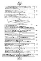
- FIG. 5 is a flowchart showing a sample SAM analysis method according to Embodiment 1.
- FIG. 5 is a flowchart showing a sample SAM analysis method according to Embodiment 1.
- a sample holder HL for holding the sample SAM is prepared.
- the sample SAM is prepared and mounted on the sample holder HL. After that, the subsequent steps S1 to S13 are performed.
- a sample SAM is a thin piece obtained in advance by processing a portion of a wafer, for example, with an FIB device.
- the semiconductor wafer includes a semiconductor substrate in which p-type or n-type impurity regions are formed, semiconductor elements such as transistors formed on the semiconductor substrate, wiring layers formed on the semiconductor elements, and the like. ing. Therefore, the sample SAM includes all or part of the semiconductor substrate, the semiconductor element, and the wiring layer. Note that the sample SAM is not limited to a portion of a semiconductor wafer, and may be a structure that is used outside of semiconductor technology.
- step S1 the control unit C5 closes the gate valve VL5, the valve VL2, the valve VL3, and the leak valve VL6, and opens the valve VL1, the valve VL4, and the leak valve VL7. Then, the high vacuum pump 40 is driven by the controller C6. Thereby, the observation chamber 10 is maintained at a high degree of vacuum, and the pretreatment chamber 20 is open to the atmosphere.
- step S2 the sample holder HL that holds the sample SAM is installed on the stage 23 of the pretreatment chamber 20.
- the transfer port 26 of the third unit 20C is opened, and the sample holder HL holding the sample SAM can be replaced through the transfer port 26 .
- step S3 the control unit C5 closes the valve VL4 and the leak valve VL7 and opens the valve VL3. Then, the roughing pump 41 is driven by the controller C7 to start roughing evacuation of the pretreatment chamber 20, and the degree of vacuum in the pretreatment chamber 20 is increased. At this time, since the valve VL4 is in the closed state, deterioration of the back pressure of the high vacuum pump 40 can be prevented.
- step S4 the vacuum gauge 24 and the controller C4 determine whether the pressure in the pretreatment chamber 20 is 20 Pa or less. If the pressure is 20 Pa or less (YES), the next step is step S5. When the pressure is higher than 20 Pa (NO), roughing evacuation from the roughing pump 41 is continued until the pressure in the pretreatment chamber 20 becomes 20 Pa or less.
- the judgment value of the pressure after rough evacuation is set to 20 Pa, but the judgment value of the pressure is not limited to 20 Pa. should be low.
- the roughing pump 41 is higher in that it evacuates to a pressure of several Pa to 100 Pa from the atmospheric pressure. It is more suitable than the vacuum pump 40. Therefore, when changing the pressure from the atmospheric pressure to about several Pa to 100 Pa, the roughing pump 41 is used to change the pressure from about several Pa to 100 Pa to about 10 ⁇ 2 to 10 ⁇ 5 Pa. , a high vacuum pump 40 is used. As a result, the overall exhaust time can be shortened.
- step S5 the control unit C5 closes the valve VL3 and opens the valve VL4 and the gate valve VL5.
- both the observation chamber 10 and the pretreatment chamber 20 are evacuated from the intake port 31a of the high vacuum pump 40 via the exhaust pipe 31 and the exhaust port 31b. Start. As a result, the degree of vacuum in the pretreatment chamber 20 is made higher than the degree of vacuum in step S3 (step S4).
- step S5 the observation chamber 10 and the pretreatment chamber 20 are evacuated by the air intake port 31a having a relatively large diameter. Therefore, it is possible to shorten the evacuation time compared to the case where the vacuum evacuation is performed by the air intake port 32a having a relatively small diameter.
- step S6 the control unit C5 closes the gate valve VL5 and opens the valve VL2.
- the pretreatment chamber 20 is evacuated from the intake port 32 a of the high vacuum pump 40 .
- step S4 the gate valve VL5 may be kept closed, the valve VL2 may be opened, and the pretreatment chamber 20 may be evacuated through the intake port 32a. be done.
- step S5 the pretreatment chamber 20 is evacuated through the air inlet 32a in a state in which the degree of vacuum in the pretreatment chamber 20 is increased using the air inlet 31a having a high exhaust speed, as in step S6. This can reduce the total time required to reach the vacuum required to start ion milling.
- step S7 the sample SAM is subjected to ion milling in the pretreatment chamber 20. That is, while the pretreatment chamber 20 is evacuated by the high vacuum pump 40, the sample SAM is processed by irradiating the sample SAM with the ion beam IB from the ion source 22 by the controller C3.
- the gate valve VL5 is closed. Therefore, it is possible to solve the problem that the observation chamber 10 is contaminated by the sputtered particles generated by the ion milling, and the problem that the Ar gas generated from the ion source 22 causes deterioration of the SEM function.
- step S8 after the ion milling is completed, the gate valve VL5 is opened by the controller C5.
- step S9 the user inserts the sample exchange rod 25 into the sample holder HL holding the sample SAM, and moves the sample holder HL from the stage 23 of the pretreatment chamber 20 to the stage 13 of the observation chamber 10.
- step S10 after the movement of the sample holder HL is completed, the control unit C4 returns the sample exchange rod 25 to the initial position, and the control unit C5 closes the gate valve VL5. Thereafter, while the observation chamber 10 is evacuated by the high vacuum pump 40, the sample SAM is observed by irradiating the sample SAM with the electron beam EB from the electron source 12 by the controller C1.
- step S11 after the observation of the sample SAM is finished, the control unit C5 opens the gate valve VL5.
- step S12 the user inserts the sample exchange rod 25 into the sample holder HL holding the sample SAM, and moves the sample holder HL from the stage 13 of the observation chamber 10 to the stage 23 of the pretreatment chamber 20.
- step S10 if the desired observation has been performed, the observation work ends. If the desired observation cannot be performed and, for example, the ion milling is insufficient, the process returns to step S6, and after the pretreatment chamber 20 is evacuated, ion milling of the sample SAM is redone.
- step S13 after the user returns the sample exchange rod 25 to the initial position, the control unit C5 closes the gate valve VL5 and the valve VL2. Then, the control unit C5 opens the leak valve VL7 to open the pretreatment chamber 20 to the atmosphere. After that, the sample holder HL holding the sample SAM is removed from the pretreatment chamber 20 via the transfer port 26 .
Landscapes
- Chemical & Material Sciences (AREA)
- Analytical Chemistry (AREA)
- Physics & Mathematics (AREA)
- Engineering & Computer Science (AREA)
- Plasma & Fusion (AREA)
- Analysing Materials By The Use Of Radiation (AREA)
- Sampling And Sample Adjustment (AREA)
Abstract
Description
<荷電粒子線装置1の構成>
以下に図1~図3を用いて、実施の形態1における荷電粒子線装置1について説明する。実施の形態1では、荷電粒子線装置1として走査型電子顕微鏡(SEM)を例示する。
上述のように、試料SAMをイオンミリングするためには、イオンビームIBが効率よく試料SAMの表面上に照射される必要がある。そのため、イオンビームIBの平均自由工程が十分に長くなるように、イオンミリングが行われる前処理室20の真空度を、高い真空度へ調整し、且つ、短時間で調整することが望ましい。
10 観察室
11 鏡筒
12 電子源
13 ステージ
14 真空計
15 コンデンサレンズ
16 対物レンズ
20 前処理室
20A~20C 第1~第3ユニット
21 鏡筒
22 イオン源
23 ステージ
24 真空計
25 試料交換棒
26 搬送口
31~34 排気管
31a~34a 吸気口
31b~34b 排気口
40 高真空ポンプ(真空ポンプ、ターボ分子ポンプ)
41 粗引ポンプ(真空ポンプ、ドライポンプ)
50 入力デバイス
51 モニタ
52 GUI画面
C0 コントローラ
C1~C7 制御部
EB 電子ビーム
HL ホルダ
IB イオンビーム
SAM 試料
VL1~VL4 バルブ
VL5 ゲートバルブ
VL6、VL7 リークバルブ
Claims (13)
- 第1排気口を有する観察室と、
前記観察室に取り付けられた第1鏡筒と、
前記第1鏡筒の内部に設けられ、且つ、第1荷電粒子ビームを照射可能な第1荷電粒子源と、
前記観察室の内部において前記第1荷電粒子源の下方に設けられ、且つ、試料を保持した試料ホルダを設置可能な第1ステージと、
ゲートバルブを介して前記観察室に接続され、且つ、第2排気口を有する前処理室と、
前記前処理室に取り付けられた第2鏡筒と、
前記第2鏡筒の内部に設けられ、且つ、第2荷電粒子ビームを照射可能な第2荷電粒子源と、
前記前処理室の内部において前記第2荷電粒子源の下方に設けられ、且つ、前記試料を保持した前記試料ホルダを設置可能な第2ステージと、
第1吸気口および第2吸気口を有する第1真空ポンプと、
前記第1吸気口および前記第1排気口に接続された第1排気管と、
前記第2吸気口および前記第2排気口に接続された第2排気管と、
前記第1排気管の途中に設けられた第1バルブと、
前記第2排気管の途中に設けられた第2バルブと、
前記第1荷電粒子源、前記第1ステージ、前記第2荷電粒子源および前記第2ステージの各々の動作を制御し、前記第1真空ポンプの駆動を制御し、且つ、前記ゲートバルブ、前記第1バルブおよび前記第2バルブの各々の開閉状態を制御するコントローラと、
前記試料を保持した前記試料ホルダが前記第2ステージ上に設置された際に、前記コントローラによって実行される解析手段と、
を備え、
前記第1吸気口および前記第1排気口の各々の口径は、前記第2吸気口および前記第2排気口の各々の口径よりも大きく、
前記解析手段は、
(a)前記ゲートバルブを開状態にし、前記第1バルブを開状態にし、前記第2バルブを閉状態にし、且つ、前記第1真空ポンプを駆動することで、前記観察室および前記前処理室の各々の真空度を高くするステップ、
(b)前記ステップ(a)の後、前記ゲートバルブを閉状態にし、且つ、前記第2バルブを開状態にするステップ、
(c)前記ステップ(b)の後、前記第1真空ポンプによって前記前処理室の真空排気を行いながら、前記第2荷電粒子源から前記試料へ前記第2荷電粒子ビームを照射することで、前記試料の加工を行うステップ、
を有する、荷電粒子線装置。 - 請求項1に記載の荷電粒子線装置において、
前記前処理室に設けられた第3排気口と、
第3吸気口を有し、且つ、達成できる真空度が前記第1真空ポンプよりも低い第2真空ポンプと、
前記第3吸気口および前記第3排気口に接続された第3排気管と、
前記第3排気管の途中に設けられた第3バルブと、
を更に備え、
前記コントローラは、前記第2真空ポンプの駆動を制御し、且つ、前記第3バルブの開閉状態を制御し、
前記解析手段は、
(d)前記ステップ(a)の前に、前記ゲートバルブを閉状態にし、前記第1バルブを開状態にし、前記第2バルブを閉状態にし、前記第3バルブを開状態にし、且つ、前記第2真空ポンプを駆動することで、前記前処理室の真空度を高くするステップ、
を更に有し、
前記ステップ(a)は、前記第3バルブを閉状態にして行われ、
前記ステップ(a)では、前記観察室および前記前処理室の各々の真空度は、前記ステップ(d)の真空度よりも高くなる、荷電粒子線装置。 - 請求項2に記載の荷電粒子線装置において、
前記前処理室の内部に設けられ、且つ、前記観察室と前記前処理室との間で前記試料ホルダを移動するための試料交換棒と、
を更に備え、
前記解析手段は、
(e)前記ステップ(c)の後、前記ゲートバルブを開状態にするステップ、
(f)前記ステップ(e)の後、ユーザによる前記試料交換棒の操作によって、前記試料を保持した前記試料ホルダを前記第2ステージから前記第1ステージへ移動するステップ、
(g)前記ステップ(f)の後、前記ゲートバルブを閉状態にするステップ、
(h)前記ステップ(g)の後、前記第1真空ポンプによって前記観察室の真空排気を行いながら、前記第1荷電粒子源から前記試料へ前記第1荷電粒子ビームを照射することで、前記試料の観察を行うステップ、
を更に有する、荷電粒子線装置。 - 請求項3に記載の荷電粒子線装置において、
前記前処理室は、互いに着脱可能な第1ユニット、第2ユニットおよび第3ユニットによって構成され、
前記第1ユニットには、前記第2鏡筒、前記第2荷電粒子源、前記第2ステージおよび第2排気口が設けられ、
前記第2ユニットには、前記ゲートバルブおよび第3排気口が設けられ、
前記第3ユニットには、前記試料交換棒が設けられている、荷電粒子線装置。 - 請求項3に記載の荷電粒子線装置において、
前記第1真空ポンプに設けられた第4排気口と、
前記第2真空ポンプに設けられた第4吸気口と、
前記第4吸気口および前記第4排気口に接続された第4排気管と、
前記第4排気管の途中に設けられた第4バルブと、
を更に備え、
前記コントローラは、前記第4バルブの開閉状態を制御し、
前記第4バルブは、前記ステップ(d)では閉状態であり、前記ステップ(a)~前記ステップ(h)では開状態である、荷電粒子線装置。 - 請求項1に記載の荷電粒子線装置において、
前記第1荷電粒子源は、電子源であり、
前記第1荷電粒子ビームは、電子ビームであり、
前記第2荷電粒子源は、イオン源であり、
前記第2荷電粒子ビームは、イオンビームである、荷電粒子線装置。 - 観察室と、
前記観察室に取り付けられた第1鏡筒と、
前記第1鏡筒の内部に設けられ、且つ、第1荷電粒子ビームを照射可能な第1荷電粒子源と、
前記観察室の内部において前記第1荷電粒子源の下方に設けられ、且つ、試料を保持した試料ホルダを設置可能な第1ステージと、
ゲートバルブを介して前記観察室に接続された前処理室と、
前記前処理室の内部に設けられ、且つ、前記観察室と前記前処理室との間で前記試料ホルダを移動するための試料交換棒と、
を備え、
前記前処理室は、互いに着脱可能な第2ユニットおよび第3ユニットによって構成され、
前記第2ユニットには、前記ゲートバルブが設けられ、
前記第3ユニットには、前記試料交換棒が設けられている、荷電粒子線装置。 - 請求項7に記載の荷電粒子線装置において、
前記前処理室に取り付けられた第2鏡筒と、
前記第2鏡筒の内部に設けられ、且つ、第2荷電粒子ビームを照射可能な第2荷電粒子源と、
前記前処理室の内部において前記第2荷電粒子源の下方に設けられ、且つ、前記試料を保持した前記試料ホルダを設置可能な第2ステージと、
を更に備え、
前記前処理室は、互いに着脱可能な第1ユニット、前記第2ユニットおよび前記第3ユニットによって構成され、
前記第1ユニットには、前記第2鏡筒、前記第2荷電粒子源および前記第2ステージが設けられている、荷電粒子線装置。 - 請求項8に記載の荷電粒子線装置において、
前記観察室に設けられた第1排気口と、
前記第1ユニットに設けられた第2排気口と、
第1吸気口および第2吸気口を有する第1真空ポンプと、
前記第1吸気口および前記第1排気口に接続された第1排気管と、
前記第2吸気口および前記第2排気口に接続された第2排気管と、
前記第1排気管の途中に設けられた第1バルブと、
前記第2排気管の途中に設けられた第2バルブと、
を更に備え、
前記第1吸気口および前記第1排気口の各々の口径は、前記第2吸気口および前記第2排気口の各々の口径よりも大きい、荷電粒子線装置。 - 請求項9に記載の荷電粒子線装置において、
前記第2ユニットに設けられた第3排気口と、
第3吸気口を有し、且つ、達成できる真空度が前記第1真空ポンプよりも低い第2真空ポンプと、
前記第3吸気口および前記第3排気口に接続された第3排気管と、
前記第3排気管の途中に設けられた第3バルブと、
を更に備えた、荷電粒子線装置。 - 請求項8に記載の荷電粒子線装置において、
前記第1荷電粒子源は、電子源であり、
前記第1荷電粒子ビームは、電子ビームであり、
前記第2荷電粒子源は、イオン源であり、
前記第2荷電粒子ビームは、イオンビームである、荷電粒子線装置。 - 第1排気口を有する観察室と、
前記観察室に取り付けられた第1鏡筒と、
前記第1鏡筒の内部に設けられ、且つ、第1荷電粒子ビームを照射可能な第1荷電粒子源と、
前記観察室の内部において前記第1荷電粒子源の下方に設けられ、且つ、試料を保持した試料ホルダを設置可能な第1ステージと、
ゲートバルブを介して前記観察室に接続され、且つ、第2排気口および第3排気口を有する前処理室と、
前記前処理室に取り付けられた第2鏡筒と、
前記第2鏡筒の内部に設けられ、且つ、第2荷電粒子ビームを照射可能な第2荷電粒子源と、
前記前処理室の内部において前記第2荷電粒子源の下方に設けられ、且つ、前記試料を保持した前記試料ホルダを設置可能な第2ステージと、
前記前処理室の内部に設けられ、且つ、前記観察室と前記前処理室との間で前記試料ホルダを移動するための試料交換棒と、
第1吸気口および第2吸気口を有する第1真空ポンプと、
第3吸気口を有し、且つ、達成できる真空度が前記第1真空ポンプよりも低い第2真空ポンプと、
前記第1吸気口および前記第1排気口に接続された第1排気管と、
前記第2吸気口および前記第2排気口に接続された第2排気管と、
前記第3吸気口および前記第3排気口に接続された第3排気管と、
前記第1排気管の途中に設けられた第1バルブと、
前記第2排気管の途中に設けられた第2バルブと、
前記第3排気管の途中に設けられた第3バルブと、
を備えた荷電粒子線装置を用いて行われる試料の解析方法であって、
(a)前記試料を保持した前記試料ホルダを、前記第2ステージ上に設置するステップ、
(b)前記ステップ(a)の後、前記ゲートバルブを閉状態にし、前記第1バルブを開状態にし、前記第2バルブを閉状態にし、前記第3バルブを開状態にし、且つ、前記第2真空ポンプを駆動することで、前記観察室および前記前処理室の各々の真空度を高くするステップ、
(c)前記ステップ(b)の後、前記ゲートバルブを開状態にし、前記第3バルブを閉状態にし、且つ、前記第1真空ポンプを駆動することで、前記前処理室の真空度を、前記ステップ(b)の真空度よりも高い真空度にするステップ、
(d)前記ステップ(c)の後、前記ゲートバルブを閉状態にし、且つ、前記第2バルブを開状態にするステップ、
(e)前記ステップ(d)の後、前記第1真空ポンプによって前記前処理室の真空排気を行いながら、前記第2荷電粒子源から前記試料へ前記第2荷電粒子ビームを照射することで、前記試料の加工を行うステップ、
(f)前記ステップ(e)の後、前記ゲートバルブを開状態にするステップ、
(g)前記ステップ(f)の後、前記試料交換棒を用いて、前記試料を保持した前記試料ホルダを前記第2ステージから前記第1ステージへ移動するステップ、
(h)前記ステップ(g)の後、前記ゲートバルブを閉状態にするステップ、
(i)前記ステップ(h)の後、前記第1真空ポンプによって前記観察室の真空排気を行いながら、前記第1荷電粒子源から前記試料へ前記第1荷電粒子ビームを照射することで、前記試料の観察を行うステップ、
を有し、
前記第1吸気口および前記第1排気口の各々の口径は、前記第2吸気口および前記第2排気口の各々の口径よりも大きい、試料の解析方法。 - 請求項12に記載の試料の解析方法において、
前記第1荷電粒子源は、電子源であり、
前記第1荷電粒子ビームは、電子ビームであり、
前記第2荷電粒子源は、イオン源であり、
前記第2荷電粒子ビームは、イオンビームである、試料の解析方法。
Priority Applications (4)
| Application Number | Priority Date | Filing Date | Title |
|---|---|---|---|
| PCT/JP2021/014821 WO2022215212A1 (ja) | 2021-04-07 | 2021-04-07 | 荷電粒子線装置および試料の解析方法 |
| JP2023512590A JP7531051B2 (ja) | 2021-04-07 | 2021-04-07 | 荷電粒子線装置および試料の解析方法 |
| KR1020237032856A KR102874837B1 (ko) | 2021-04-07 | 2021-04-07 | 하전 입자선 장치 및 시료의 해석 방법 |
| US18/284,425 US12651723B2 (en) | 2021-04-07 | 2021-04-07 | Charged particle beam device and sample analysis method |
Applications Claiming Priority (1)
| Application Number | Priority Date | Filing Date | Title |
|---|---|---|---|
| PCT/JP2021/014821 WO2022215212A1 (ja) | 2021-04-07 | 2021-04-07 | 荷電粒子線装置および試料の解析方法 |
Publications (1)
| Publication Number | Publication Date |
|---|---|
| WO2022215212A1 true WO2022215212A1 (ja) | 2022-10-13 |
Family
ID=83545268
Family Applications (1)
| Application Number | Title | Priority Date | Filing Date |
|---|---|---|---|
| PCT/JP2021/014821 Ceased WO2022215212A1 (ja) | 2021-04-07 | 2021-04-07 | 荷電粒子線装置および試料の解析方法 |
Country Status (4)
| Country | Link |
|---|---|
| US (1) | US12651723B2 (ja) |
| JP (1) | JP7531051B2 (ja) |
| KR (1) | KR102874837B1 (ja) |
| WO (1) | WO2022215212A1 (ja) |
Cited By (1)
| Publication number | Priority date | Publication date | Assignee | Title |
|---|---|---|---|---|
| EP4621825A3 (en) * | 2024-03-21 | 2025-10-15 | Jeol Ltd. | Charged particle beam system and method of controlling charged particle beam system |
Citations (2)
| Publication number | Priority date | Publication date | Assignee | Title |
|---|---|---|---|---|
| WO2016166825A1 (ja) * | 2015-04-15 | 2016-10-20 | 株式会社日立ハイテクノロジーズ | 荷電粒子線装置、およびその真空排気方法 |
| WO2018020649A1 (ja) * | 2016-07-29 | 2018-02-01 | 株式会社日立ハイテクノロジーズ | 荷電粒子線装置 |
Family Cites Families (2)
| Publication number | Priority date | Publication date | Assignee | Title |
|---|---|---|---|---|
| JP2000195460A (ja) | 1998-12-28 | 2000-07-14 | Canon Inc | 走査電子顕微鏡による分析方法 |
| KR102181455B1 (ko) * | 2018-12-28 | 2020-11-23 | 참엔지니어링(주) | 시료 관찰 장치 및 방법 |
-
2021
- 2021-04-07 US US18/284,425 patent/US12651723B2/en active Active
- 2021-04-07 WO PCT/JP2021/014821 patent/WO2022215212A1/ja not_active Ceased
- 2021-04-07 JP JP2023512590A patent/JP7531051B2/ja active Active
- 2021-04-07 KR KR1020237032856A patent/KR102874837B1/ko active Active
Patent Citations (2)
| Publication number | Priority date | Publication date | Assignee | Title |
|---|---|---|---|---|
| WO2016166825A1 (ja) * | 2015-04-15 | 2016-10-20 | 株式会社日立ハイテクノロジーズ | 荷電粒子線装置、およびその真空排気方法 |
| WO2018020649A1 (ja) * | 2016-07-29 | 2018-02-01 | 株式会社日立ハイテクノロジーズ | 荷電粒子線装置 |
Cited By (1)
| Publication number | Priority date | Publication date | Assignee | Title |
|---|---|---|---|---|
| EP4621825A3 (en) * | 2024-03-21 | 2025-10-15 | Jeol Ltd. | Charged particle beam system and method of controlling charged particle beam system |
Also Published As
| Publication number | Publication date |
|---|---|
| KR102874837B1 (ko) | 2025-10-23 |
| US12651723B2 (en) | 2026-06-09 |
| JPWO2022215212A1 (ja) | 2022-10-13 |
| US20240170250A1 (en) | 2024-05-23 |
| JP7531051B2 (ja) | 2024-08-08 |
| KR20230150849A (ko) | 2023-10-31 |
Similar Documents
| Publication | Publication Date | Title |
|---|---|---|
| JP5090255B2 (ja) | 原位置でのstemサンプル作製方法 | |
| KR100885940B1 (ko) | 하전입자선에 의한 검사장치 및 그 검사장치를 사용한장치제조방법 | |
| US9378925B2 (en) | TEM sample preparation | |
| US10157722B2 (en) | Inspection device | |
| CN106783493B (zh) | 一种真空气氛处理装置、样品观测系统及方法 | |
| JPWO2002013227A1 (ja) | シートビーム式検査装置 | |
| JP7531051B2 (ja) | 荷電粒子線装置および試料の解析方法 | |
| JP6807393B2 (ja) | 荷電粒子線装置 | |
| US20240404780A1 (en) | Semiconductor processing apparatus | |
| JP2017526152A (ja) | サンプルの準備及びコーティングのためのイオンビーム装置及び方法 | |
| CN107430972A (zh) | 带电粒子束装置及其真空排气方法 | |
| KR101922004B1 (ko) | 이온 비임 생성을 위한 혁신적인 소스 조립체 | |
| US20250174428A1 (en) | Segmented endpointing for sample preparation | |
| CN112166486A (zh) | 用于制作和放置薄片的装置 | |
| TWI850851B (zh) | 用於排氣及流動調節操作之系統及方法 | |
| WO2013179808A1 (ja) | 荷電粒子装置 | |
| JP2008193119A (ja) | 荷電粒子線による検査装置及びその検査装置を用いたデバイス製造方法 | |
| WO2013129196A1 (ja) | 荷電粒子線装置及び荷電粒子線照射方法 | |
| JP2007292507A (ja) | 透過型電子顕微鏡の試料作製方法および集束イオンビーム装置 | |
| JP4221428B2 (ja) | 荷電粒子線による検査装置及びその検査装置を用いたデバイス製造方法 | |
| JP6879663B2 (ja) | 荷電粒子ビーム装置 | |
| US20250308840A1 (en) | Sample preparation with non-uniform dose | |
| WO2023157226A1 (ja) | 真空処理装置 | |
| JP2002252261A (ja) | 半導体検査装置及び半導体露光装置 | |
| JP2008511957A (ja) | マイクロカラムを利用したポータブル電子顕微鏡 |
Legal Events
| Date | Code | Title | Description |
|---|---|---|---|
| 121 | Ep: the epo has been informed by wipo that ep was designated in this application |
Ref document number: 21936016 Country of ref document: EP Kind code of ref document: A1 |
|
| WWE | Wipo information: entry into national phase |
Ref document number: 2023512590 Country of ref document: JP |
|
| ENP | Entry into the national phase |
Ref document number: 20237032856 Country of ref document: KR Kind code of ref document: A |
|
| WWE | Wipo information: entry into national phase |
Ref document number: 18284425 Country of ref document: US |
|
| NENP | Non-entry into the national phase |
Ref country code: DE |
|
| 122 | Ep: pct application non-entry in european phase |
Ref document number: 21936016 Country of ref document: EP Kind code of ref document: A1 |
|
| WWG | Wipo information: grant in national office |
Ref document number: 18284425 Country of ref document: US |