WO2022210918A1 - 可撓性ステンレス箔および可撓性発光デバイス - Google Patents
可撓性ステンレス箔および可撓性発光デバイス Download PDFInfo
- Publication number
- WO2022210918A1 WO2022210918A1 PCT/JP2022/016116 JP2022016116W WO2022210918A1 WO 2022210918 A1 WO2022210918 A1 WO 2022210918A1 JP 2022016116 W JP2022016116 W JP 2022016116W WO 2022210918 A1 WO2022210918 A1 WO 2022210918A1
- Authority
- WO
- WIPO (PCT)
- Prior art keywords
- stainless steel
- steel foil
- less
- bending
- flexible
- Prior art date
- Legal status (The legal status is an assumption and is not a legal conclusion. Google has not performed a legal analysis and makes no representation as to the accuracy of the status listed.)
- Ceased
Links
Images

Classifications
-
- C—CHEMISTRY; METALLURGY
- C22—METALLURGY; FERROUS OR NON-FERROUS ALLOYS; TREATMENT OF ALLOYS OR NON-FERROUS METALS
- C22C—ALLOYS
- C22C38/00—Ferrous alloys, e.g. steel alloys
- C22C38/18—Ferrous alloys, e.g. steel alloys containing chromium
- C22C38/40—Ferrous alloys, e.g. steel alloys containing chromium with nickel
- C22C38/58—Ferrous alloys, e.g. steel alloys containing chromium with nickel with more than 1.5% by weight of manganese
-
- B—PERFORMING OPERATIONS; TRANSPORTING
- B21—MECHANICAL METAL-WORKING WITHOUT ESSENTIALLY REMOVING MATERIAL; PUNCHING METAL
- B21B—ROLLING OF METAL
- B21B1/00—Metal-rolling methods or mills for making semi-finished products of solid or profiled cross-section; Sequence of operations in milling trains; Layout of rolling-mill plant, e.g. grouping of stands; Succession of passes or of sectional pass alternations
- B21B1/40—Metal-rolling methods or mills for making semi-finished products of solid or profiled cross-section; Sequence of operations in milling trains; Layout of rolling-mill plant, e.g. grouping of stands; Succession of passes or of sectional pass alternations for rolling foils which present special problems, e.g. because of thinness
-
- B—PERFORMING OPERATIONS; TRANSPORTING
- B32—LAYERED PRODUCTS
- B32B—LAYERED PRODUCTS, i.e. PRODUCTS BUILT-UP OF STRATA OF FLAT OR NON-FLAT, e.g. CELLULAR OR HONEYCOMB, FORM
- B32B15/00—Layered products comprising a layer of metal
- B32B15/04—Layered products comprising a layer of metal comprising metal as the main or only constituent of a layer, which is next to another layer of the same or of a different material
-
- B—PERFORMING OPERATIONS; TRANSPORTING
- B32—LAYERED PRODUCTS
- B32B—LAYERED PRODUCTS, i.e. PRODUCTS BUILT-UP OF STRATA OF FLAT OR NON-FLAT, e.g. CELLULAR OR HONEYCOMB, FORM
- B32B15/00—Layered products comprising a layer of metal
- B32B15/18—Layered products comprising a layer of metal comprising iron or steel
-
- C—CHEMISTRY; METALLURGY
- C21—METALLURGY OF IRON
- C21D—MODIFYING THE PHYSICAL STRUCTURE OF FERROUS METALS; GENERAL DEVICES FOR HEAT TREATMENT OF FERROUS OR NON-FERROUS METALS OR ALLOYS; MAKING METAL MALLEABLE, e.g. BY DECARBURISATION OR TEMPERING
- C21D9/00—Heat treatment, e.g. annealing, hardening, quenching or tempering, adapted for particular articles; Furnaces therefor
- C21D9/46—Heat treatment, e.g. annealing, hardening, quenching or tempering, adapted for particular articles; Furnaces therefor for sheet metals
-
- C—CHEMISTRY; METALLURGY
- C22—METALLURGY; FERROUS OR NON-FERROUS ALLOYS; TREATMENT OF ALLOYS OR NON-FERROUS METALS
- C22C—ALLOYS
- C22C38/00—Ferrous alloys, e.g. steel alloys
-
- C—CHEMISTRY; METALLURGY
- C22—METALLURGY; FERROUS OR NON-FERROUS ALLOYS; TREATMENT OF ALLOYS OR NON-FERROUS METALS
- C22C—ALLOYS
- C22C38/00—Ferrous alloys, e.g. steel alloys
- C22C38/001—Ferrous alloys, e.g. steel alloys containing N
-
- C—CHEMISTRY; METALLURGY
- C22—METALLURGY; FERROUS OR NON-FERROUS ALLOYS; TREATMENT OF ALLOYS OR NON-FERROUS METALS
- C22C—ALLOYS
- C22C38/00—Ferrous alloys, e.g. steel alloys
- C22C38/002—Ferrous alloys, e.g. steel alloys containing In, Mg, or other elements not provided for in one single group C22C38/001 - C22C38/60
-
- C—CHEMISTRY; METALLURGY
- C22—METALLURGY; FERROUS OR NON-FERROUS ALLOYS; TREATMENT OF ALLOYS OR NON-FERROUS METALS
- C22C—ALLOYS
- C22C38/00—Ferrous alloys, e.g. steel alloys
- C22C38/02—Ferrous alloys, e.g. steel alloys containing silicon
-
- C—CHEMISTRY; METALLURGY
- C22—METALLURGY; FERROUS OR NON-FERROUS ALLOYS; TREATMENT OF ALLOYS OR NON-FERROUS METALS
- C22C—ALLOYS
- C22C38/00—Ferrous alloys, e.g. steel alloys
- C22C38/04—Ferrous alloys, e.g. steel alloys containing manganese
-
- C—CHEMISTRY; METALLURGY
- C22—METALLURGY; FERROUS OR NON-FERROUS ALLOYS; TREATMENT OF ALLOYS OR NON-FERROUS METALS
- C22C—ALLOYS
- C22C38/00—Ferrous alloys, e.g. steel alloys
- C22C38/06—Ferrous alloys, e.g. steel alloys containing aluminium
-
- C—CHEMISTRY; METALLURGY
- C22—METALLURGY; FERROUS OR NON-FERROUS ALLOYS; TREATMENT OF ALLOYS OR NON-FERROUS METALS
- C22C—ALLOYS
- C22C38/00—Ferrous alloys, e.g. steel alloys
- C22C38/18—Ferrous alloys, e.g. steel alloys containing chromium
- C22C38/38—Ferrous alloys, e.g. steel alloys containing chromium with more than 1.5% by weight of manganese
-
- C—CHEMISTRY; METALLURGY
- C22—METALLURGY; FERROUS OR NON-FERROUS ALLOYS; TREATMENT OF ALLOYS OR NON-FERROUS METALS
- C22C—ALLOYS
- C22C38/00—Ferrous alloys, e.g. steel alloys
- C22C38/18—Ferrous alloys, e.g. steel alloys containing chromium
- C22C38/40—Ferrous alloys, e.g. steel alloys containing chromium with nickel
- C22C38/42—Ferrous alloys, e.g. steel alloys containing chromium with nickel with copper
-
- C—CHEMISTRY; METALLURGY
- C22—METALLURGY; FERROUS OR NON-FERROUS ALLOYS; TREATMENT OF ALLOYS OR NON-FERROUS METALS
- C22C—ALLOYS
- C22C38/00—Ferrous alloys, e.g. steel alloys
- C22C38/18—Ferrous alloys, e.g. steel alloys containing chromium
- C22C38/40—Ferrous alloys, e.g. steel alloys containing chromium with nickel
- C22C38/44—Ferrous alloys, e.g. steel alloys containing chromium with nickel with molybdenum or tungsten
-
- C—CHEMISTRY; METALLURGY
- C22—METALLURGY; FERROUS OR NON-FERROUS ALLOYS; TREATMENT OF ALLOYS OR NON-FERROUS METALS
- C22C—ALLOYS
- C22C38/00—Ferrous alloys, e.g. steel alloys
- C22C38/18—Ferrous alloys, e.g. steel alloys containing chromium
- C22C38/40—Ferrous alloys, e.g. steel alloys containing chromium with nickel
- C22C38/48—Ferrous alloys, e.g. steel alloys containing chromium with nickel with niobium or tantalum
-
- C—CHEMISTRY; METALLURGY
- C22—METALLURGY; FERROUS OR NON-FERROUS ALLOYS; TREATMENT OF ALLOYS OR NON-FERROUS METALS
- C22C—ALLOYS
- C22C38/00—Ferrous alloys, e.g. steel alloys
- C22C38/60—Ferrous alloys, e.g. steel alloys containing lead, selenium, tellurium, or antimony, or more than 0.04% by weight of sulfur
-
- F—MECHANICAL ENGINEERING; LIGHTING; HEATING; WEAPONS; BLASTING
- F21—LIGHTING
- F21V—FUNCTIONAL FEATURES OR DETAILS OF LIGHTING DEVICES OR SYSTEMS THEREOF; STRUCTURAL COMBINATIONS OF LIGHTING DEVICES WITH OTHER ARTICLES, NOT OTHERWISE PROVIDED FOR
- F21V21/00—Supporting, suspending, or attaching arrangements for lighting devices; Hand grips
- F21V21/14—Adjustable mountings
-
- H—ELECTRICITY
- H05—ELECTRIC TECHNIQUES NOT OTHERWISE PROVIDED FOR
- H05B—ELECTRIC HEATING; ELECTRIC LIGHT SOURCES NOT OTHERWISE PROVIDED FOR; CIRCUIT ARRANGEMENTS FOR ELECTRIC LIGHT SOURCES, IN GENERAL
- H05B33/00—Electroluminescent light sources
- H05B33/12—Light sources with substantially two-dimensional [2D] radiating surfaces
- H05B33/22—Light sources with substantially two-dimensional [2D] radiating surfaces characterised by the chemical or physical composition or the arrangement of auxiliary dielectric or reflective layers
-
- B—PERFORMING OPERATIONS; TRANSPORTING
- B32—LAYERED PRODUCTS
- B32B—LAYERED PRODUCTS, i.e. PRODUCTS BUILT-UP OF STRATA OF FLAT OR NON-FLAT, e.g. CELLULAR OR HONEYCOMB, FORM
- B32B2307/00—Properties of the layers or laminate
- B32B2307/50—Properties of the layers or laminate having particular mechanical properties
- B32B2307/538—Roughness
-
- B—PERFORMING OPERATIONS; TRANSPORTING
- B32—LAYERED PRODUCTS
- B32B—LAYERED PRODUCTS, i.e. PRODUCTS BUILT-UP OF STRATA OF FLAT OR NON-FLAT, e.g. CELLULAR OR HONEYCOMB, FORM
- B32B2307/00—Properties of the layers or laminate
- B32B2307/50—Properties of the layers or laminate having particular mechanical properties
- B32B2307/54—Yield strength; Tensile strength
-
- B—PERFORMING OPERATIONS; TRANSPORTING
- B32—LAYERED PRODUCTS
- B32B—LAYERED PRODUCTS, i.e. PRODUCTS BUILT-UP OF STRATA OF FLAT OR NON-FLAT, e.g. CELLULAR OR HONEYCOMB, FORM
- B32B2307/00—Properties of the layers or laminate
- B32B2307/50—Properties of the layers or laminate having particular mechanical properties
- B32B2307/546—Flexural strength; Flexion stiffness
-
- B—PERFORMING OPERATIONS; TRANSPORTING
- B32—LAYERED PRODUCTS
- B32B—LAYERED PRODUCTS, i.e. PRODUCTS BUILT-UP OF STRATA OF FLAT OR NON-FLAT, e.g. CELLULAR OR HONEYCOMB, FORM
- B32B2311/00—Metals, their alloys or their compounds
- B32B2311/30—Iron, e.g. steel
-
- B—PERFORMING OPERATIONS; TRANSPORTING
- B32—LAYERED PRODUCTS
- B32B—LAYERED PRODUCTS, i.e. PRODUCTS BUILT-UP OF STRATA OF FLAT OR NON-FLAT, e.g. CELLULAR OR HONEYCOMB, FORM
- B32B2457/00—Electrical equipment
- B32B2457/20—Displays, e.g. liquid crystal displays, plasma displays
Definitions
- the present invention relates to a stainless steel foil having high durability against repeated bending with a small curvature and a movable light emitting device including the same.
- Patent Document 1 measures to reduce inclusions in stainless steel foil
- Patent Document 2 measures to reduce the average peak interval of the surface cross-sectional curve in the direction perpendicular to the rolling direction of stainless steel foil.
- Patent Document 2 measures to reduce the average peak interval of the surface cross-sectional curve in the direction perpendicular to the rolling direction of stainless steel foil.
- a stainless steel foil used for flexible display substrates a stainless steel foil having an average arithmetic mean roughness (Ra) of 50 nm or less in the rolling direction of the stainless steel foil and in the direction perpendicular to the rolling direction has been devised (Patent Document 3).
- the curvature of this stainless steel foil for flexible displays is assumed to be relatively large from the description of the claims.
- a substrate made of stainless steel foil with a thin insulating film on which a circuit is formed is required to have smoothness so as not to impair the resolution of the display.
- Patent Document 4 proposes an organic light-emitting device that includes a flexible conductive substrate made of stainless steel or titanium and a thin film transistor formed on the conductive substrate. This light-emitting device relates to a system for applying a bias to a conductive substrate, and the required property of the flexible substrate is conductivity, and repeated bending is not assumed.
- Patent Document 5 describes the use of stainless steel as a reinforcing material for light emitting panels such as organic EL, but it is described in the same manner as plastic, aluminum, and silicone rubber, which generally have low strength, and is in demand in recent years. Applications for severe repeated bending are not envisioned.
- the object of the present invention is to clarify the requirements for achieving the necessary durability in order to increase the durability against repeated bending under severe bending conditions required for foldable displays and rollable displays, which has not been required so far.
- Another object of the present invention is to provide a stainless steel foil that satisfies the conflicting conditions of the maximum height roughness (Rz) in the bending direction and the strength of the stainless steel foil.
- the present invention includes the following aspects.
- the thickness is 0.05 mm or less, the ratio of the maximum valley depth Rv to the Rz (Rv/Rz) is 0.6 or less, and the elongation at break when the tensile strength is measured is 1 % or more and 2% or less, the flexible stainless steel foil according to (1).
- the Rz is 0.30 ⁇ m or less
- the number of times of repeated bending until a crack with a length of 5 mm or more occurs on the surface of the stainless steel foil is 100000 times or more
- the components of the stainless steel foil, in % by mass, are C: 0.15% or less, Si: 1.00% or less, Mn: 2.00% or less, P: 0.045% or less, S: 0.04% or less.
- the present invention provides a stainless steel foil that simultaneously satisfies contradictory conditions of maximum height roughness in the bending direction and strength in order to increase durability against repeated bending under severe bending conditions required for foldable displays and rollable displays. do.
- the thickness is 0.1 mm or less
- the tensile strength is 1800 MPa or more
- the maximum height roughness Rz obtained from the roughness curve of the surface of the stainless steel foil measured in the same direction as the tensile direction is 0.
- the thickness is 0.35 ⁇ m or less, and it is possible to provide a reinforcing material for use in organic EL displays, etc., which are exposed to particularly severe repeated bending.
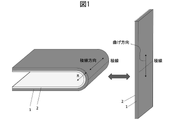
- FIGS. 1 to 3 Examples of usage forms of the stainless steel foil of the invention are shown in FIGS. 1 to 3.
- FIG. FIG. 1 is an example of a display panel for foldable electronic equipment
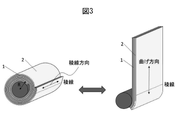
- FIGS. 2 and 3 are examples of display panels for rollable electronic equipment. All of these figures are simplified to explain how the stainless steel foil of the present invention is used.
- the stainless steel foil 1 of the present invention is used by bonding light emitting elements 2, such as organic EL display elements, with an adhesive or the like.
- FIG. 1 shows an example in which the light emitting element 2 is attached inside the stainless steel foil 1
- the light emitting element may be attached outside the stainless steel foil 1 .
- the stainless steel foil is subjected to repeated bending in a completely closed state and a 180° open state.
- the angle of repeated bending of the stainless steel foil is called the expansion angle
- the closed state is the reference (0°)
- this is the "closed angle”
- the most open state is the "open angle”.
- the minimum closing angle is 0° and the maximum opening angle is 360°. Therefore, the range of expansion angles is 0° or more and less than 360°.
- the closing angle is 0°
- the opening angle is 180°
- the deployment angle is 180°.
- the closing angle, opening angle, and expansion angle of the stainless steel foil are not necessarily limited, but the stainless steel foil of the present invention repeats the expansion angle of 180°. It is a foil that is resistant to bending. In applications such as foldable terminals typified by mobile phones, it is often used in a flat state like a smartphone by completely unfolding from a completely folded position as shown in Fig. 1.
- the degrees are a closed angle of 0°, an open angle of 180°, and an expanded angle of 180°.
- the opening angle does not need to be 180°, and it is preferable that the opening angle can be expanded to about 135° from the visibility of the display, and the flexible stainless steel foil of the present invention can be applied. .
- the cross section of the stainless steel foil 1 is bent into an arc defined by the bending radius R at the bent location.
- the bending radius R defined in the present invention is the outer circumference when the bending is approximated to a circular arc when bent as shown in FIG.
- R be the radius of the surface. If R is made smaller, the thickness of the electronic device in the folded state can be reduced, and the stainless steel foil of the present invention is useful.
- the line forming the crease is called a ridgeline
- the direction of the ridgeline is called a ridgeline direction.
- the bending direction the direction perpendicular to the ridgeline in the plane.
- the bent part receives bending strain locally near the ridge line, but in the rollable display shown in Figs. It covers an area close to the entire area and changes.
- the stainless steel foil used in the rollable display as shown in FIGS. 2 and 3 has a closed angle of 0°, an open angle of 180°, and an expanded angle of 180°. As shown in Fig.
- the maximum radius is constant when the display is used with a wide width. R (mm). If the bending radius R can be reduced, the slide type rollable display as shown in FIG. 2 can be thinned as a whole, and the roll type rollable display as shown in FIG. 3 can be reduced in storage space. can be done.
- the highly durable stainless steel foil of the present invention is very useful for rollable displays.
- the present invention provides a rolled stainless steel foil having a thickness t of 0.1 mm or less, a tensile strength of 1800 MPa or more in at least one of the rolling direction and the direction perpendicular to the rolling direction, and
- the flexible stainless steel foil has a maximum height roughness Rz of 0.35 ⁇ m or less obtained from the measured surface roughness curve of the stainless steel foil.
- the thickness is 0.05 mm or less
- the ratio of the maximum valley depth Rv to the Rz (Rv/Rz) is 0.6 or less
- the elongation at break when the tensile strength is measured is 1% or more and 2% or less.
- R / t 100 (R is the bending radius (mm), t (mm) is the thickness) in the same direction as the tensile direction, and then to 0 °
- the flexible stainless steel has a bending habit of 100000 times or more until a crack having a length of 5 mm or more occurs on the surface of the stainless steel foil when it is repeatedly returned, and has a bending habit of 170° or more in terms of opening angle.
- Foil. R/t which is defined as the preferred stainless steel foil of the present invention, is an index representing the severity of bending in consideration of the stress and strain received by the material.
- R/t 100, which is used as an index for the stainless steel foil of the present invention, has rarely been seen in applications of metal foils that require repeated bending durability at a deployment angle of 180°.
- the component of the stainless steel foil is not limited, but since the stainless steel foil mainly used for electronic equipment is the object, iron (Fe) with good corrosion resistance is the main component, specifically 50 10.5% by mass or more of chromium (Cr). Henceforth, in the present invention, unless otherwise specified, the component values of the stainless steel foil are represented by % by mass.
- the stainless steel foil of the present invention must achieve extremely high strength, so there are not many varieties of it among the materials currently in commercial use. For example, C: 0.15% or less, Si: 1.00% or less, Mn: 2.00% or less, P: 0.045% or less, S: 0.030% or less, Ni: 6.00-8. 00%, Cr: 16.00 to 18.00%, N: 0.20% or less, and a stainless steel foil containing C: 0.07 to 0.10%, Si: 0.75% Below, P: 0.030% or less, S: 0.030% or less, N: 0.25-0.40%, Ni: 5.50-7.00-%, Cr: 17.50-20.00 ⁇ %, and Mn: 9.0 to 12.0%.
- the former stainless steel foil is called SUS301 and SUS301L in JIS standards, and is sometimes used as a spring material. It turned out that it is possible to manufacture it by devising wholeheartedly.
- the latter stainless steel foil is a product called NSSC130S manufactured by Nippon Steel Stainless Co., Ltd. This is also manufactured by devising a manufacturing method to meet the strength and roughness requirements of the stainless steel foil of the present invention. It turns out that it can be done. This material is non-magnetic and useful in applications where magnetism is averse.
- the structure of the stainless steel foil of the present invention is not particularly limited, austenitic stainless steel with a developed martensite structure is suitable. Some austenitic stainless steels form a stress- or strain-induced martensitic phase upon working.
- the stainless steel foil of the present invention desirably has a structure structure in which a martensite structure with high strength induced by this working is developed. Further, the martensite structure preferably accounts for 50% or more, more preferably 60% or more in terms of area ratio, and forms a mixed phase structure with the austenite phase, so that the stainless steel foil of the present invention has durability against bending within the range specified. You can get sex.
- the area ratio of the martensitic structure is measured by EBSD (electron backscattering diffraction method) installed in an FE-SEM (field emission electron microscope) and evaluated on the polished surface of the foil surface perpendicular to the thickness direction of the foil. and In the case of SUS301 foil, which undergoes martensitic transformation by working, the surface is smoothed by chemical polishing in order to prevent martensitic transformation due to mechanical polishing.
- the measurement conditions are a magnification of 1500 times, a measurement area of 60 ⁇ 120 ⁇ m, and a measurement interval of 0.08 ⁇ m.
- the crystal structure and its orientation at each measurement point can be determined from the diffraction line from each measurement point.
- the area ratio of the martensite phase is obtained from the ratio of the measurement points of the phase determined to be the martensite phase.
- the phase having a body-centered cubic (bcc) can be regarded as the martensite phase, and the ratio of points to the entire crystal structure is the area ratio of the martensite phase.
- the coexisting structure of the austenite phase and the martensite phase can be obtained, for example, by hard rolling a metastable austenitic stainless steel such as SUS304 or SUS301 to transform the austenite into work-induced martensite.
- a metastable austenitic stainless steel such as SUS304 or SUS301
- the stainless steel foil manufactured in this manner is preferable as the stainless steel foil of the present invention because it is composed of a martensite phase with high strength and an austenite phase in which strain is accumulated.
- SUS301 and SUS301L are materials that have the above components and the balance is iron and inevitable impurities.
- SUS301L is a material in which nitrogen is intentionally added in the range of 0.2% or less instead of reducing the carbon component value to 0.03%.
- the strength of SUS301L is easier to increase, and it is a more desirable material if it can be manufactured so that the roughness falls within the specified range of the present invention.
- Materials derived from these JIS standard steel grades to which Nb is added have high fatigue strength, and are particularly desirable if they can be manufactured so that the strength and maximum height roughness Rz are within the specified ranges of the present invention.
- the phase structure of the stainless steel foil of the present invention is formed using deformation-induced transformation and the area ratio of the martensite phase is 50% or more, preferably 60% or more, the crystal grains are long in the rolling direction and in the foil thickness direction.
- the austenite phase is distributed in an island-like structure, and the formation of such a multiphase structure inhibits crack propagation. This improves bending durability.
- the stainless steel foil of the present invention has a bending radius R of 1 mm or more and 10 mm or less, and can be repeatedly bent for use.
- the thickness t (mm) of the foil used under these conditions is 0.1 mm or less, R / t is 30 or more and 120 or less, and the deployment angle is 135 ° or more. expected to be used. If it is used in applications where R/t is less than 30, it will tend to bend and it will be difficult to meet the required rupture life.
- conventional stainless steel foils that do not meet the requirements for tensile strength and maximum height roughness (Rz) of the foil of the present invention satisfy bending habit and rupture life. be able to.
- a foldable device when there is no need to distinguish between a foldable device and a rollable device, both are collectively referred to as a foldable device.
- the thickness t of the stainless steel foil used for the foldable device it is generally 0.02 mm or more for the purpose of reinforcing the light emitting element.
- the number of bends required for a foldable device depends on the application of the device, but at least 100,000 times is necessary. , that the crack introduced into the surface of the stainless steel foil is 5 mm or less, which is a criterion required for the preferred stainless steel foil of the present invention.
- the flexible stainless steel foil of the present invention can be used integrally by bonding with a flexible light-emitting display element represented by an organic EL display element used in a foldable device. If there is a crack on the surface of the curved portion of the stainless steel foil, a large amount of deformation is locally generated, resulting in an abnormal display of the light-emitting display device and, in some cases, breakage. Therefore, it is desirable that no cracks occur, but cracks of up to 5 mm are permissible due to the cushioning action of the adhesive layer between the light-emitting display element and the stainless steel foil.
- Foldable devices are expected to become smaller, thinner, and lighter in the future.
- the allowable range of bending habit required for the stainless steel foil of the present invention is 100,000 times in the bending direction of the stainless foil after performing a repeated bending test at a deployment angle of 180 ° or more.
- the opening angle caused by plastic deformation along the bent ridgeline of the stainless steel foil is measured without applying a force such as gravity, and the free opening angle is preferably 170° or more.
- 175° or more is desirable, and 180° with no bending tendency is more desirable.
- To measure the bending tendency place the stainless steel foil on a flat desk so that the ridgeline of the bending is perpendicular to the plane of the desk top, and take a picture with a digital camera focusing on the upper edge from directly above. This is done by measuring the angle attached to the stainless steel foil using the image.
- the repeated bending test of the stainless steel foil is a test under the conditions of a closed angle of 0° and an open angle of 180° using a clamshell type repeated bending tester.
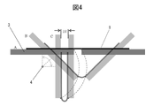
- FIG. 4 schematically shows the bending motion in the repeated bending test.
- the clamshell type cyclic bending tester is equipped with a set of two holding plates 3, to which the stainless steel foil 1 is attached and the holding plate is tilted to give forced bending displacement to the stainless steel foil 1. .
- FIG. 4 shows state A with an opening angle of 180° and state C with a closing angle of about 90° and 0°.
- One of the two holding plates tilts while rotating around the drive shaft 4, and the other holding plate maintains the same angle. Keep parallel and follow so that the distance does not change.
- the stainless steel foil can be repeatedly bent without applying any load other than bending.
- Yuasa System Equipment Co., Ltd., no-load clamshell bending tester, type DR11MR can be mentioned.
- the stainless steel foil When the distance between the two holding plates when they are closed is 2R, the stainless steel foil is subjected to bending displacement forming an arc with a bending radius R. Depending on the thickness and mechanical properties of the stainless steel foil, the bent portion may not form a complete arc. It is the radius of the outer peripheral surface of the stainless steel foil when regarded as an arc.
- the stainless steel foil is cut into a size of 40 mm wide x 150 mm long, and the center of the long side and the width direction are measured so that the bending ridgeline direction.
- the width and length of the stainless steel foil shall be measured by reading down to 1/10 of the minimum scale on a scale with a minimum scale of 1 mm, and shall be cut out so as to have a tolerance range of ⁇ 0.5 mm.
- the thickness is measured at 10 different locations in the sample using a single-sphere micrometer with a minimum reading accuracy of micrometers or less, one side of which is flat and one side of which is spherical, and the average value is taken as 0.0. It shall be taken up to 1 ⁇ m.
- the gap length shall be set with an accuracy of 0.1 mm or less so that the default R/t is within ⁇ 3%.
- Both ends of the bending ridge are polished with #1500 or more emery paper before attaching the stainless steel foil to the holding plate so that cracks do not occur from the ends of the stainless steel foil.
- the frequency of repeated bending that determines the bending speed is 1 Hz.
- the stainless steel foil of the present invention must have a bending strength of 1800 MPa or more. This is a necessary condition for both bending habit and destruction against repeated bending, and is especially essential for suppressing bending habit. If the Young's modulus of the stainless steel foil is almost the same, it is straightforward to define the presence or absence of the bending habit by the strength of the yield strength. There are many, and it is specified by the maximum strength.
- the strength of the stainless steel foil is 1800 MPa or more, preferably 2000 MPa or more. If the strength is less than 1800 MPa, the stainless steel foil of the present invention develops a large bending tendency under the specified conditions, which is not preferable.
- a sample cut into a shape complying with JIS No. 13B and having a length of 150 mm is used.
- the test shall be carried out at a crosshead speed of 50 mm / min while reading the load applied to the load cell, and the maximum load until breakage of the test piece.
- the value obtained by dividing by the area is the intensity.
- the elongation value it shall be measured using an extensometer. If there is a difference in tensile strength in the cutting direction in the plane of the stainless steel foil, the maximum value should be 1800 MPa or more.
- the direction in which the tensile strength satisfies 1800 MPa or more is used as the bending direction.
- the flexible stainless steel foil of the present invention is used as a reinforcing material for light-emitting devices such as lighting and displays, which can be folded (bent) in two or rolled into a roll by adhering light-emitting electronic elements on the foil surface. be. These devices do not simply form curved surfaces, but are subjected to repeated bending with small curvatures.
- an organic EL display element which is one of light-emitting electronic elements, is an element capable of high color rendering and high-definition display, and is used for displays of high-end televisions and mobile phones. Bending habits and breaking cracks in the reinforcing material and peeling of the reinforcing material and the adhesive degrade the quality of the display at that part, so particularly high durability is required.
- the stainless steel foil of the present invention is not a substrate on which a light-emitting electronic device is directly formed, it does not need to have a smooth surface.
- roughness measured in the bending direction has a large effect on bending durability.
- an important requirement in the present invention is compatibility between strength and roughness, and the direction of roughness measurement must match the direction of strength measurement in the tensile test.
- Strength and roughness in the same direction of measurement are paired requirements. It is normal for the roughness in the plane of a rolled stainless steel foil to be different in the measurement direction, and the stainless steel foil of the present invention must satisfy the prescribed strength and roughness in any direction in the plane.
- the direction satisfying the prescribed values of the present invention is used as the bending direction.
- the prescribed value of roughness in the bending direction will be described below.
- the maximum height roughness Rz of the stainless steel foil surface measured in the bending direction must be 0.35 ⁇ m or less, preferably 0.30 ⁇ m or less, and further Desirably, it is 0.25 ⁇ m or less, ideally 0.20 ⁇ m or less.
- the maximum height roughness Rz of the stainless steel foil surface measured in the bending direction must be 0.35 ⁇ m or less, preferably 0.30 ⁇ m or less, and further Desirably, it is 0.25 ⁇ m or less, ideally 0.20 ⁇ m or less.
- the maximum stress (bending principal stress) occurs in the bending direction of the surface of the stainless steel foil forming the bending radius R, and the roughness when measured in the same direction as the bending principal stress direction of the surface of the stainless steel foil This is because if there is a trough in the curve, stress concentration occurs at this location.
- a fine crack once introduced propagates in the direction perpendicular to the principal stress direction in the process of repeated bending, if there are valleys in that direction, the crack propagates along the valleys.
- Typical indices of roughness include maximum height roughness Rz defined in JIS B0601 (2001) and arithmetic mean roughness Ra. Although there is some correlation between the maximum height roughness Rz and Ra, the durability of the stainless steel foil of the present invention under repeated bending conditions strongly correlates with the maximum height roughness Rz. Further, the repeated bending durability is strongly dependent on Rz in the bending direction, and the correlation between Rz in other directions is small. If the adhesion strength between the light-emitting electronic element and the adhesive decreases, peeling will occur in the bent area, causing display defects or destruction from the light-emitting electronic element.
- the two-dimensional unevenness in the direction perpendicular to the bending direction has little effect on the propagation of cracks that progress in the direction of the ridgeline forming the folds in the foil, and the effect on the bending durability of the stainless steel foil itself is small. Also, the contact area with the adhesive is increased, and the peeling of the adhesive has a good effect on the durability of the light emitting panel itself.
- the roughness in one direction is important from the viewpoint of bending durability.
- Rz is desirably 0.05 ⁇ m or more from the viewpoint of industrial feasibility and adhesion strength to the adhesive. This is because if the Rz in the bending direction is reduced to this level, the Rz in the other directions also becomes smaller, making it difficult to ensure the strength of adhesion to the adhesive due to the anchor effect. That is, the stainless steel foil of the present invention is not necessarily required to have strength and smoothness in all directions of the stainless steel foil. , the direction in which the tensile strength is 1800 MPa or more exists within the plane of the stainless steel foil. Based on such an idea, the stainless steel foil of the present invention can be practically produced as an industrial material.
- the value measured by the stylus method is adopted according to JISB0601 (2001).
- the measurement conditions are a measurement length of 1.25 mm, a cutoff ( ⁇ c) of 0.25 mm, a cutoff ( ⁇ s) of 0.0025 mm, a stylus scanning speed of 0.3 mm/sec, and a measurement load of 0.7 mN.
- values using a cone with a radius of 2 ⁇ mR and a tip opening angle of 60° are adopted. Measurements are taken at five or more different points on each surface of the stainless steel foil, and the average value is adopted.
- the roughness measured on the worse side shall be adopted.
- the thickness is 0.05 mm or less, and the ratio of the maximum valley depth Rv to the Rz (Rv/Rz) is 0.6 or less, and when the tensile strength is measured
- the stainless steel foil has a breaking elongation of 1% or more and 2% or less.
- the stainless steel foil of the present invention is particularly suitable for applications where the bending curvature R is 5 mm or less and subjected to repeated bending, and is particularly effective when it is necessary to reduce the foil thickness to 0.05 mm or less. Considering the yield of the material, it is preferable to use the sheet by cutting it with the rolling direction as the bending direction. The smaller the thickness of the foil, the greater the effect of Rz.
- the elongation at break is high. It is desirable to be in the range of 2% or less.
- a stainless steel foil having a high breaking elongation generally has a low strength, but even a high-strength stainless steel foil that satisfies the prescribed strength of the present invention may have a breaking elongation exceeding 2%.
- Such a stainless steel foil has a clear yield point, and when strain beyond that point is applied, large plastic deformation occurs and the bending tendency increases.
- the display of a foldable device is generally composed of a reinforcing metal foil, an organic EL element, and an adhesive that bonds them together. Metal foil is used as a supplement for rigidity.
- the bent portion of the display can be bent in free space, it is assumed that a large amount of strain is applied momentarily due to vibration or the like, exceeding the static design strain.
- a large amount of strain is applied momentarily due to vibration or the like, exceeding the static design strain.
- the stainless steel foil of the present invention it is preferable to use a material that has a clear yield point and a large breaking elongation even if the strength is the same, and a material that greatly increases stress with respect to strain even if it exceeds the yield point. It was found that a material with an elongation of 2% or less is good. However, poorly ductile materials of less than 1% are less preferred.
- One way to increase the tensile strength of the foil against bending is to increase the total rolling reduction.
- the carbon and nitrogen in the stainless steel foil are rearranged in defects such as dislocations formed by working strain, improving the yield strength and tensile strength. It is possible to suppress peculiarities and increase the number of times of bending until the crack length reaches 5 mm.
- the rolling direction When the rolling direction is set to the bending direction, a process that focuses on reducing oil marks may be adopted. Further, when the direction perpendicular to the rolling direction is desired to be the bending direction, measures may be taken to reduce the transfer of grinding marks. In order to suppress oil marks, the oil film thickness of the roll bite should be reduced by lowering the rolling speed or increasing the rolling rate per pass. In order to suppress the unevenness in the direction perpendicular to the rolling direction, it is sufficient to increase the grinding number of the work roll to make a roll with a small work roll roughness (arithmetic mean roughness Ra), and add a polishing process to further reduce the roughness. It can also be used as a work roll. In addition, a work roll that has been blasted to eliminate grinding marks and has a dimple-structured surface can also be used.
- the flexible stainless steel foil of the present invention should be improved in roughness in the bending direction (maximum height roughness Rz).
- the main purpose of countermeasures is to reduce streak-like irregularities that are caused by oil marks and are continuous in the direction perpendicular to the rolling direction. Concavities and convexities in a direction other than the bending direction caused by the multiphase structure of the martensite phase and the austenite phase are convenient because they can be used to increase the adhesion strength with the adhesive.
- the method for manufacturing the flexible stainless steel foil of the present invention will be described below based on the above manufacturing guidelines.
- Foil rolling is generally carried out using a multistage rolling mill to control thickness and roughness and to stabilize mechanical properties including strength.
- a cold rolling mill with 12 or more stages is particularly desirable for rolling.
- the total rolling reduction means the reduction rate (%) of the thickness of the steel material before and after the final cold rolling process.
- the total rolling reduction is defined by the following formula (A).
- Total rolling reduction (%) 100 - (thickness of steel material after final cold rolling process) / (thickness of steel material before final cold rolling process) x 100 (A)
- the total rolling reduction is more preferably 50% or more, still more preferably 55% or more. If the total rolling reduction is less than 45%, it becomes difficult to obtain a tensile strength of 1800 MPa or more.
- the upper limit of the total rolling reduction is not particularly set, the total rolling reduction is preferably 80% or less because the number of passes generally increases and the oil mark becomes deeper when the total rolling reduction is increased. Moreover, the number of passes in the final cold rolling step is preferably 4 to 10 times.
- the oil marks are also controlled by the average rolling speed in the final cold rolling process, and the average rolling speed for all passes is preferably 210 mpm or less in order to obtain a smooth surface. It is more preferably 150 mpm or less, still more preferably 100 mpm or less. If the average rolling speed is too high, the amount of rolling oil entrained increases, which promotes the formation of oil marks and may increase the surface roughness measured in the rolling direction.
- the surface roughness of the steel material in the final cold rolling process is also controlled by the roughness perpendicular to the work roll rolling rotation direction.
- the work roll roughness Ra perpendicular to the rolling rotation direction of the work rolls is preferably 0.40 ⁇ m or less, more preferably 0.30 ⁇ m or less, further preferably 0.30 ⁇ m or less. 10 ⁇ m, ideally 0.08 ⁇ m or less. If the work roll roughness is too large, the surface roughness Rz of the steel material also increases, and sufficient bending durability may not be obtained.
- the lower limit is preferably a work roll roughness Ra of 0.01 ⁇ m or more in order to shorten the time required for grinding or polishing the work roll.
- the heat treatment process refers to a bright annealing process or a low temperature heat treatment process.
- bright annealing is performed, and after the final cold rolling process, low temperature heat treatment is performed.
- the purpose of the bright annealing process is to soften the material. Characteristically, by annealing in a reducing atmosphere containing hydrogen such as ammonia decomposition gas, it is possible to suppress the formation of an oxide film and suppress surface defects in the subsequent cold rolling process.
- the heat treatment temperature in the bright annealing step is preferably 900 to 1200°C. If the heat treatment temperature is too low, the softening of the steel material will not proceed sufficiently, resulting in an increase in the number of cold rolling passes.
- the purpose of the low-temperature heat treatment step is to strengthen the structure by rearrangement of carbon and nitrogen into lattice defects as described above.
- the heat treatment temperature in this step is preferably 300 to 800.degree.
- Heat treatment after cold working is not essential, but if the heat treatment temperature is too low, diffusion of carbon and nitrogen becomes difficult, and structural strengthening does not proceed sufficiently.
- the elongation value may be larger than the preferred breaking elongation value of the present invention.
- the heat treatment temperature is too high, the martensite phase, which is a factor of high strength, disappears and working strain is released, so that the necessary tensile strength cannot be obtained.
- the flexible stainless steel foil of the present invention is a foldable device in which a flexible light-emitting electronic element represented by a planar organic EL display element is attached to the surface, and the screen is folded or rolled into a roll for storage. It is used as a reinforcing material to increase the mechanical strength and durability of light-emitting electronic devices. At present, there is no use for the reinforcing material that requires durability against repeated bending specified in the present invention other than flexible light emitting devices including organic EL display elements, but if there is a similar use for severe repeated bending in one direction , the flexible stainless steel foil of the present invention is applicable.
- the flexible stainless steel foil of the present invention will be described in more detail below with reference to examples.
- the examples shown below are merely examples of the flexible stainless steel foil of the present invention, and the flexible stainless steel foil of the present invention is not limited to the examples shown below.
- Example 1 A stainless steel foil sample having a thickness of 30 ⁇ m to 100 ⁇ m was produced and tested for durability by a repeated bending test.
- the manufactured stainless steel foil is ferritic SUS430 (steel type name 430: Fe-17.0% Cr-0.07% C-0.4% Si-0.6% Mn-0.02% P-0.001% S).
- Austenitic stainless steel SUS301 (steel type name 301: Fe-17.0%Cr-6.5%Ni-0.12%C-0.06%N-0.5%Si-0.6%Mn-0.03 % P-0.0008% S).
- Austenitic NSSC130S (steel grade name 130S: Fe-17.7% Cr-6.5% Ni-11.6% Mn-0.09% C-0.31% N-0.48% Si-0.022% P).
- a stainless steel foil sample was produced as follows. Ferritic and austenitic stainless steel foils with a plate thickness of 300 to 400 ⁇ m were purchased, and the austenitic stainless steel foils were subjected to a cold rolling process and a bright annealing process once or twice.
- the bright annealing process is intended to soften the material, and is annealed at a temperature of 900° C. to 1200° C. in a reducing atmosphere containing hydrogen such as ammonia decomposition gas.
- the thickness was set to 30 ⁇ m to 100 ⁇ m.
- a sample for evaluation was manufactured through a washing process and a low-temperature heat treatment (TA) process.
- TA low-temperature heat treatment
- a 12-high reverse cold rolling mill was used for rolling.
- the total rolling reduction in the cold rolling process was 50% to 87%, and the number of passes was 5 to 15 times.
- the average rolling speed for all passes was 50-300 mpm.
- the work rolls used were prepared in three stages, with the work roll roughness Ra perpendicular to the rolling rotation direction being controlled from 0.08 or less to 0.2 ⁇ m or more and less than 0.3 ⁇ m.
- a low temperature heat treatment was performed after the final cold rolling. This step is abbreviated as TA because the stainless steel foil is continuously annealed by applying tension in the length direction.
- the heat treatment temperature in the TA process was set at 350 to 900° C., and evaluation was also carried out on some finished samples without low-temperature heat treatment.
- a tensile test, a surface roughness measurement, and a repeated bending test were performed on the stainless steel foil produced as described above in various directions.
- the SUS301 foil was subjected to structural evaluation by EBSD (electron beam backscatter diffraction method). In the structural evaluation of the SUS301 foil by EBSD, the ratio of the martensite phase in the stainless steel foil was determined.
- the crystal phase in the sample was identified with an EBSD analysis device installed in an FE-SEM (Field Emission Electron Microscope) on the stainless steel foil surface from which surface distortion was removed by chemical polishing.
- the measurement conditions were a magnification of 1500 times, a measurement area of 60 ⁇ 120 ⁇ m, and a measurement interval of 0.08 ⁇ m. The measurement was performed for three fields of view at different locations.
- SU70 manufactured by Hitachi High-Technologies Corporation was used as the FE-SEM, and OIM manufactured by TSL Solutions was used as the EBSD apparatus.
- a 150 mm-long test piece having a shape conforming to JIS No. 13B test piece was cut out from the stainless steel foil produced as described above, and a contact-type strain gauge with a gauge length of 50 mm was attached, and the crosshead speed was 50 mm/. min. was carried out at the speed of
- the test direction was either the rolling (RD) direction or its perpendicular (TD) direction, which was the same direction as the test direction of the repeated bending test.
- the load until breakage was monitored with a load cell, and the value obtained by dividing the maximum load by the cross-sectional area of the sample before the test was taken as the strength.
- the breaking elongation was defined as the ratio of the elongation value measured by the contact strain gauge when the sample broke to the initial measured length (gauge length) expressed as a percentage.
- the strength and elongation at break were averages of values obtained by measuring 5 test pieces.
- the surface of the stainless steel foil manufactured as described above was measured in the same direction as the tensile direction in the tensile test using a stylus-type surface roughness measuring instrument.
- a stylus-type surface roughness measuring instrument As a measuring device, Tokyo Seimitsu's stylus-type surface roughness measuring instrument (with tabletop anti-vibration table), model: SURFCOM130A was used, and evaluation was made according to JISB0601 (2001).
- the measurement conditions were a measurement length of 1.25 mm, a cutoff ( ⁇ c) of 0.25 mm, a cutoff ( ⁇ s) of 0.0025 mm, a stylus scanning speed of 0.3 mm/sec, and a measurement load of 0.7 mN.
- the probe used was a cone with a tip radius of 2 ⁇ m and an opening angle of 60°.
- the roughness curve is obtained from the contour curve, which is the displacement profile corresponding to the unevenness of the foil surface of the probe measured in one direction, and the maximum height roughness, which is the roughness index of the stainless steel foil of the present invention.
- Rz maximum height roughness
- Rv maximum valley depth
- the sample for the repeated bending test was cut out from the stainless steel foil produced as described above into a sample measuring 40 mm in width and 100 mm in length, with the length direction aligned with either the RD or TD direction.
- a no-load clamshell bending tester type DR11MR, manufactured by Yuasa System Co., Ltd. was used.
- the operation of bending 180° at the center and opening it back 180° was repeated.
- the gap at the time of bending and closing the bending curvature can be changed. As shown in FIG. 4, by setting the gap to 2R, the bent portion with the bending radius R is formed.
- the cycle of repeated bending was set to 1 Hz. The test was performed until the number of times of repeated bending reached 100,000 times.
- the crack evaluation was A for a sample that had no cracks at all, and the crack evaluation for a sample with a crack of 5 mm or more was D, and the maximum crack length was 3 mm.
- Crack evaluation C was given when the crack was more than 5 mm
- crack evaluation B was given when the crack was observed but the maximum crack was less than 3 mm.
- most of the samples evaluated as B were less than 1 mm, and the crack propagated relatively quickly when the crack length exceeded 1 mm.
- the free opening angle remaining on the stainless steel foil was measured by removing the test piece from the test jig so as not to apply a large force to the test piece.
- the opening angle changes due to its own weight.
- the image was taken with a digital camera, and the angle attached to the stainless steel foil was measured using the image.
- the measurement was performed by placing plates against both sides of the stainless steel foil so that the stainless steel foil did not change its bending habit.
- Table 1 shows a summary of the manufacturing method of the stainless steel foil and the evaluation results.
- Total rolling rate (%) arithmetic mean roughness Ra ( ⁇ m) representing work roll roughness, number of passes (times) in final rolling process, rolling speed (m/min.), low-temperature heat treatment, which are important parameters of the manufacturing method.
- Annealing temperature (TA temperature: (°C)) after the process is shown.
- RD indicates that the measurement direction was the rolling direction
- TD indicates that the measurement direction was perpendicular to the thickness direction.
- EBSD measurement is performed on the premise that it consists of two phases, an austenite phase with a face-centered cubic structure and a martensite phase with a body-centered cubic structure, and is determined as martensite for all measurement points.
- the score obtained, that is, the area ratio of the martensite phase was presented as the M phase ratio (%).
- the M phase ratio is a value obtained by rounding off the average value at three different locations.
- the stainless steel foil of the present invention requires both characteristics of microcracks and bending habit as durability, those with a D rating in either the crack evaluation or the bending habit evaluation are rejected.
- Sample numbers 1 to 11 are stainless steel foils with a thickness of 40 ⁇ m.
- the steel material 430 of sample number 1 is a ferritic stainless steel, which is relatively inexpensive, and the surface of which can be easily smoothed.
- Steel material 130S and steel material 301 are austenitic stainless steel.
- Steel material 130S is a stainless steel foil mainly composed of an austenite phase, but steel material 301 is found to have a composite structure with an austenite phase containing a large amount of martensite phase by X-ray diffraction and electron beam backscattering diffraction methods. rice field. This is because the austenite phase was transformed into martensite by strong cold working. A repeated bending test was performed on these stainless steel foils at a bending radius of 4.0 mm.
- the stainless steel foils of Sample No. 2, Sample No. 3, and Sample Nos. 6 to 11, whose tensile strength and maximum roughness Rz satisfy the material conditions of the present invention, are excellent in durability as a foil double device of the present invention. It is stainless steel foil.
- the sample of sample number 1, whose Rz was smaller and superior than sample numbers 2 and 3, had elongated cracks, had a large bending habit, and was inferior in terms of bending durability, and could not satisfy the criteria of the present invention.
- rice field This is because the steel material 430 mainly composed of a ferrite phase is easy to finish a smooth surface, but cannot obtain sufficient strength.
- Sample No. 2 is austenitic stainless steel and is characterized by being non-magnetic. Therefore, it is useful as a reinforcing stainless steel foil for foldable devices that require non-magnetism. Almost no permanent deformation (bending habit) was observed at the ridge line.
- sample No. 4 cracked when the number of bends was smaller than that of sample No. 2, although the strength was high. This is because the roughness in the bending direction was rough. Although the roughness of the work rolls used for the final rolling was the same, the rolling speed was high, and as a result, oil traces became large, resulting in a particularly large Rz in the rolling direction and a large maximum valley depth Rv.
- the 301 steel material which is a different steel type, has the same effect on the repeated bending durability of Rz and Rv/Rz. Furthermore, the 301 steel foil is affected by the structure due to the difference in manufacturing conditions. Among the steel materials 301, sample number 5 did not develop any cracks at all, but had a significantly increased bending habit. This is because the TA temperature was too high, softening occurred, and the strength decreased, so that the bending strain under the bending conditions in this test exceeded the yield point and large plastic deformation occurred.
- Sample No. 5 and Sample No. 6 have high ductility like Sample No. 1, and in the region of low cycle fatigue such as this test condition, it is believed that the larger the elongation at break, the better the durability, but this time it was carried out. Through tests, it was found that the breaking elongation of the stainless steel foil of the present invention is preferably 2% or less.
- Sample No. 5 and Sample No. 6 materials also have a small percentage of martensitic phase (M phase) within the sample. This is because these materials were transformed into an austenite phase, which is an equilibrium phase, by raising the TA temperature after rolling.
- M phase martensitic phase
- the ratio of the martensite phase in the 301 steel foil, which has excellent durability, is 60% or more.
- Island-like austenite phases appear to be distributed.
- the size of the austenite phase was 20 ⁇ m or less in the TD direction, but it had an elongated shape in the RD direction.
- Such a structure increases the strength and yield strength, and further prevents the propagation of microscopic fatigue cracks generated by repeated bending.
- sample No. 7 and Sample No. 8 have the same cold rolling conditions. It is finished by heat treatment at °C. Although no significant difference was observed in strength and roughness, sample No. 7 had a lower ratio of martensite phase. This is probably because the total rolling reduction was small, but the TA at 350°C increased the ratio of the martensite phase. As a result, although the difference in strength is not large, the stress-strain obtained in the tensile test is significantly different. The elongation at break became small.
- sample number 9 is SUS301 finished without performing low temperature heat treatment (TA) after cold rolling.
- TA low temperature heat treatment
- Sample No. 10 and Sample No. 11 are the results showing that the difference in cold rolling pass schedule caused a difference in durability. Samples 10 and 11 differ in the number of passes during the final cold working. In sample No. 10, since the number of passes was increased, the oil marks became large, and Rz, especially Rv, became large. increased. On the other hand, Sample No. 11 reduced the number of passes, resulting in a stainless steel foil with high strength and a smooth surface. An attempt was made to further reduce the number of passes, but breakage during rolling also increased.
- Sample Nos. 12, 13, and 14 are steel 301 foils with a thickness of about 100 ⁇ m.
- X-ray diffraction and EBSD electron beam backscatter diffraction method
- Sample No. 12 does not meet the strength standards in directions other than the TD direction, including the RD direction, but it satisfies the strength and roughness conditions in the TD direction and has durability against 100,000 repeated bendings in the TD direction.
- a stainless steel foil of the present invention On the other hand, the foil of Sample 13, which had a larger roll count, had a larger surface roughness in the TD direction and did not meet the requirements of the present invention, resulting in a particularly short rupture life.
- Sample No. 14 is a foil whose strength in the RD direction satisfies the present invention as a result of increasing the total rolling reduction.
- the rolling (RD) direction and the in-plane perpendicular (TD) direction tend to increase the strength in the latter direction, and a material with a large breaking elongation can be obtained.
- Intensities in the RD direction equivalent to the intensities in the TD direction of sample Nos. 12 and 13 were obtained. It was found that if the strength and surface properties are equivalent, the bending durability when bent in the RD direction is better. Therefore, it was found that when used in a foldable device, it is preferable to bend in the RD direction. At this time, it is important to control unevenness caused by oil marks, and it is necessary to devise special measures for the total rolling rate and the number of passes so as to satisfy the strength.
- Sample No. 15 and Sample No. 16 are foils of steel material 301 with a thickness of about 50 ⁇ m.
- X-ray diffraction and EBSD electron beam backscatter diffraction
- the control of the surface irregularities by the roughness of the rolls and the number of passes is effective for controlling the irregularities in the rolling (RD) direction and the TD direction, which is the direction perpendicular to the rolling (RD) direction.
- the influence on unevenness in directions other than these is relatively small.
- the stainless steel foil of the present invention is intended to be used as a reinforcing material in a foldable device by attaching a planar light-emitting electronic element with an adhesive, if the surface roughness is small, the adhesion to the adhesive can be ensured. it gets harder. From the viewpoint of reducing the roughness in the bending direction and ensuring the roughness in other directions to ensure adhesion, it is effective to control the surface unevenness in one direction by the roughness of the rolls and the number of passes.
- Sample Nos. 17 to 19 are examples of manufacturing and evaluating materials suitable for the scope of the present invention with a thickness of 30 ⁇ m.
- Work rolls with a work roll roughness Ra of 0.1 ⁇ m or less are used, and the total rolling rate is reduced to 50%, while the rolling speed is set to 80 mpm or less, thereby suppressing heat generated during cold working.
- the tensile strength was 1900 MPa or more, the Rz in that direction was 0.30 ⁇ m or less, and a stainless steel foil having both strength and roughness could be produced.
- the bending tendency was small and the durability of 100,000 cycles could be ensured.
- the number of final rolling passes is set to 5 times, and the work roll roughness is reduced to 0.1 ⁇ m or less, further to 0.08 ⁇ m or less. 25 ⁇ m, further 0.20 ⁇ m or less, and durability of 100,000 times under severe conditions of R/t of 75, 67, or 50 and a deployment angle of 180° could be ensured.
- Sample Nos. 17-19 are stainless steel foils consisting of an austenite phase and a martensite phase containing a particularly large amount of martensite phase.
- the crystal grains are elongated in the rolling direction and have a lamellar structure with small grain sizes in the foil pressing direction. It looks like a structure in which island-like austenite phases are dispersed.
- the test was stopped when a crack began to occur, and the surface of the stainless steel foil was polished and observed.
- the crack generally propagated in the direction of the ridge line of the bend, but in the middle An austenite phase was observed at the tip of the location where the propagation of the crack was hindered, such as by changing the direction of propagation or bifurcating.
- both sides through which the crack passed were martensite phases. It was found that the crack progresses while transforming the austenite phase into the martensite phase, and the austenite phase has the effect of hindering the propagation of the crack.
- the high-strength martensitic phase formed as a result of strong cold working plays an important role in suppressing the bending habit under severe repeated bending conditions, but it also suppresses the propagation of cracks perpendicular to the direction of crack propagation. In addition to reducing the roughness in the bending direction, the existence of the austenite phase coexisting with the martensite phase is considered to be more effective.
- the stainless steel foil of the present invention could be obtained by making it into the final product as a final product, or by refining and finishing under the condition that the TA temperature is 700° C. or less.
- the total rolling rate is 65% or more and 80% or less
- the number of passes is 5 times or more and 8 times or less
- average rolling It was found that the speed should be 205 mpm or less and the TA temperature should be 350° C. or more and 700° C. or less.
Landscapes
- Chemical & Material Sciences (AREA)
- Engineering & Computer Science (AREA)
- Mechanical Engineering (AREA)
- Materials Engineering (AREA)
- Metallurgy (AREA)
- Organic Chemistry (AREA)
- Physics & Mathematics (AREA)
- Thermal Sciences (AREA)
- Crystallography & Structural Chemistry (AREA)
- General Engineering & Computer Science (AREA)
- Metal Rolling (AREA)
Priority Applications (4)
| Application Number | Priority Date | Filing Date | Title |
|---|---|---|---|
| KR1020237028076A KR102957428B1 (ko) | 2021-03-31 | 2022-03-30 | 가요성 스테인리스박 및 가요성 발광 디바이스 |
| US18/284,260 US12460284B2 (en) | 2021-03-31 | 2022-03-30 | Flexible stainless steel foil and flexible light emitting device |
| CN202280026431.8A CN117157422A (zh) | 2021-03-31 | 2022-03-30 | 可挠性不锈钢箔及可挠性发光设备 |
| JP2023511498A JPWO2022210918A1 (https=) | 2021-03-31 | 2022-03-30 |
Applications Claiming Priority (2)
| Application Number | Priority Date | Filing Date | Title |
|---|---|---|---|
| JP2021-060087 | 2021-03-31 | ||
| JP2021060087 | 2021-03-31 |
Publications (1)
| Publication Number | Publication Date |
|---|---|
| WO2022210918A1 true WO2022210918A1 (ja) | 2022-10-06 |
Family
ID=83459580
Family Applications (1)
| Application Number | Title | Priority Date | Filing Date |
|---|---|---|---|
| PCT/JP2022/016116 Ceased WO2022210918A1 (ja) | 2021-03-31 | 2022-03-30 | 可撓性ステンレス箔および可撓性発光デバイス |
Country Status (4)
| Country | Link |
|---|---|
| US (1) | US12460284B2 (https=) |
| JP (1) | JPWO2022210918A1 (https=) |
| CN (1) | CN117157422A (https=) |
| WO (1) | WO2022210918A1 (https=) |
Cited By (2)
| Publication number | Priority date | Publication date | Assignee | Title |
|---|---|---|---|---|
| JP7513827B1 (ja) | 2023-11-01 | 2024-07-09 | 日鉄ステンレス株式会社 | オーステナイト系ステンレス鋼板及び携帯電子機器用部品 |
| WO2024181462A1 (ja) * | 2023-02-28 | 2024-09-06 | 日鉄ケミカル&マテリアル株式会社 | 曲げ部材及びオーステナイト系ステンレス鋼箔 |
Families Citing this family (1)
| Publication number | Priority date | Publication date | Assignee | Title |
|---|---|---|---|---|
| KR102854963B1 (ko) * | 2020-10-13 | 2025-09-04 | 닛테츠 케미컬 앤드 머티리얼 가부시키가이샤 | 오스테나이트계 스테인리스 강박 |
Citations (2)
| Publication number | Priority date | Publication date | Assignee | Title |
|---|---|---|---|---|
| WO2017030148A1 (ja) * | 2015-08-19 | 2017-02-23 | 新日鉄住金マテリアルズ株式会社 | ステンレス鋼箔 |
| WO2017154981A1 (ja) * | 2016-03-09 | 2017-09-14 | 日立金属株式会社 | マルテンサイト系ステンレス鋼箔およびその製造方法 |
Family Cites Families (8)
| Publication number | Priority date | Publication date | Assignee | Title |
|---|---|---|---|---|
| JPH0678566B2 (ja) | 1988-06-08 | 1994-10-05 | 新日本製鐵株式会社 | 疲労特性に優れたステンレス鋼箔の製造方法 |
| JP4401816B2 (ja) | 2004-02-27 | 2010-01-20 | 日鉱金属株式会社 | 疲労特性に優れたメタルドーム用準安定オーステナイトステンレス鋼帯およびメタルドーム |
| JP4409346B2 (ja) | 2004-04-22 | 2010-02-03 | 新日鉄マテリアルズ株式会社 | 耐久性に優れたばね用オーステナイト系ステンレス鋼箔およびその製造方法 |
| JP2006212686A (ja) * | 2005-02-07 | 2006-08-17 | Toyo Seihaku Kk | スイッチのバネ材用ステンレス鋼箔 |
| JP4316558B2 (ja) * | 2005-06-28 | 2009-08-19 | 三星モバイルディスプレイ株式會社 | 有機発光表示装置 |
| JP4824960B2 (ja) | 2005-07-21 | 2011-11-30 | 日本精線株式会社 | ステンレス鋼高強度極細平線の製造方法 |
| CN102026743B (zh) * | 2008-05-16 | 2015-02-11 | 新日铁住金高新材料株式会社 | 柔性显示器用不锈钢箔 |
| US9588549B2 (en) | 2014-02-28 | 2017-03-07 | Semiconductor Energy Laboratory Co., Ltd. | Electronic device |
-
2022
- 2022-03-30 JP JP2023511498A patent/JPWO2022210918A1/ja active Pending
- 2022-03-30 WO PCT/JP2022/016116 patent/WO2022210918A1/ja not_active Ceased
- 2022-03-30 CN CN202280026431.8A patent/CN117157422A/zh active Pending
- 2022-03-30 US US18/284,260 patent/US12460284B2/en active Active
Patent Citations (2)
| Publication number | Priority date | Publication date | Assignee | Title |
|---|---|---|---|---|
| WO2017030148A1 (ja) * | 2015-08-19 | 2017-02-23 | 新日鉄住金マテリアルズ株式会社 | ステンレス鋼箔 |
| WO2017154981A1 (ja) * | 2016-03-09 | 2017-09-14 | 日立金属株式会社 | マルテンサイト系ステンレス鋼箔およびその製造方法 |
Cited By (4)
| Publication number | Priority date | Publication date | Assignee | Title |
|---|---|---|---|---|
| WO2024181462A1 (ja) * | 2023-02-28 | 2024-09-06 | 日鉄ケミカル&マテリアル株式会社 | 曲げ部材及びオーステナイト系ステンレス鋼箔 |
| JP7513827B1 (ja) | 2023-11-01 | 2024-07-09 | 日鉄ステンレス株式会社 | オーステナイト系ステンレス鋼板及び携帯電子機器用部品 |
| WO2025094450A1 (ja) * | 2023-11-01 | 2025-05-08 | 日鉄ステンレス株式会社 | オーステナイト系ステンレス鋼板及び携帯電子機器用部品 |
| JP2025076180A (ja) * | 2023-11-01 | 2025-05-15 | 日鉄ステンレス株式会社 | オーステナイト系ステンレス鋼板及び携帯電子機器用部品 |
Also Published As
| Publication number | Publication date |
|---|---|
| CN117157422A (zh) | 2023-12-01 |
| JPWO2022210918A1 (https=) | 2022-10-06 |
| KR20230132832A (ko) | 2023-09-18 |
| US20240150880A1 (en) | 2024-05-09 |
| US12460284B2 (en) | 2025-11-04 |
Similar Documents
| Publication | Publication Date | Title |
|---|---|---|
| WO2022210918A1 (ja) | 可撓性ステンレス箔および可撓性発光デバイス | |
| US8961713B2 (en) | Stainless steel foil for flexible display use | |
| US10144985B2 (en) | Steel sheet for can and method for manufacturing the same | |
| JP5958038B2 (ja) | 外圧に対する缶胴部の座屈強度が高く、成形性および成形後の表面性状に優れた缶用鋼板およびその製造方法 | |
| WO2014038510A1 (ja) | ステンレス鋼板およびその製造方法 | |
| JP6165369B1 (ja) | ステンレス鋼箔 | |
| JPWO2018194135A1 (ja) | 絞り缶用冷延鋼板、及びその製造方法 | |
| JP5930144B1 (ja) | 絞り缶用鋼板及びその製造方法 | |
| KR20170002551A (ko) | 마르텐사이트계 스테인리스 강판 및 메탈 가스켓 | |
| JPWO2016035235A1 (ja) | ステンレス冷延鋼板用素材 | |
| JP2017190469A (ja) | 絞り缶用冷延鋼板及びその製造方法 | |
| KR102957428B1 (ko) | 가요성 스테인리스박 및 가요성 발광 디바이스 | |
| JP2014238447A (ja) | 定着部材用の金属基材及びその製造方法、定着部材および定着装置 | |
| JP7400707B2 (ja) | 鋼板及びその製造方法 | |
| KR101967748B1 (ko) | 압연동박 | |
| KR101460931B1 (ko) | 압연 동박 | |
| TWI788625B (zh) | 鈦銅箔及鈦銅箔之製造方法 | |
| JP7447362B2 (ja) | チタン合金箔及びディスプレーパネル、並びにディスプレーパネルの製造方法 | |
| JP2021188081A (ja) | オーステナイト系ステンレス鋼板及びその製造方法 | |
| US12305247B2 (en) | Stainless steel sheet and methods for manufacturing the same | |
| WO2022163160A1 (ja) | ステンレス鋼板およびその製造方法 | |
| JP6439666B2 (ja) | ロールフォーム加工性および溶接後の真円度に優れた3ピース缶用鋼板およびその製造方法、ならびに3ピース缶の製造方法 |
Legal Events
| Date | Code | Title | Description |
|---|---|---|---|
| 121 | Ep: the epo has been informed by wipo that ep was designated in this application |
Ref document number: 22781128 Country of ref document: EP Kind code of ref document: A1 |
|
| ENP | Entry into the national phase |
Ref document number: 2023511498 Country of ref document: JP Kind code of ref document: A |
|
| ENP | Entry into the national phase |
Ref document number: 20237028076 Country of ref document: KR Kind code of ref document: A |
|
| WWE | Wipo information: entry into national phase |
Ref document number: 1020237028076 Country of ref document: KR |
|
| WWE | Wipo information: entry into national phase |
Ref document number: 202317063427 Country of ref document: IN |
|
| WWE | Wipo information: entry into national phase |
Ref document number: 18284260 Country of ref document: US |
|
| NENP | Non-entry into the national phase |
Ref country code: DE |
|
| 122 | Ep: pct application non-entry in european phase |
Ref document number: 22781128 Country of ref document: EP Kind code of ref document: A1 |
|
| WWG | Wipo information: grant in national office |
Ref document number: 18284260 Country of ref document: US |
|
| WWR | Wipo information: refused in national office |
Ref document number: 1020237028076 Country of ref document: KR |
|
| WWC | Wipo information: continuation of processing after refusal or withdrawal |
Ref document number: 1020237028076 Country of ref document: KR |