WO2022210699A1 - 車載用アンテナ装置 - Google Patents
車載用アンテナ装置 Download PDFInfo
- Publication number
- WO2022210699A1 WO2022210699A1 PCT/JP2022/015403 JP2022015403W WO2022210699A1 WO 2022210699 A1 WO2022210699 A1 WO 2022210699A1 JP 2022015403 W JP2022015403 W JP 2022015403W WO 2022210699 A1 WO2022210699 A1 WO 2022210699A1
- Authority
- WO
- WIPO (PCT)
- Prior art keywords
- antenna
- vehicle
- antenna device
- case
- antennas
- Prior art date
Links
- 230000004308 accommodation Effects 0.000 claims abstract description 12
- 239000000758 substrate Substances 0.000 claims description 92
- 239000002184 metal Substances 0.000 description 92
- 229910052751 metal Inorganic materials 0.000 description 92
- 230000003071 parasitic effect Effects 0.000 description 68
- 238000010586 diagram Methods 0.000 description 43
- 239000004020 conductor Substances 0.000 description 14
- 230000005404 monopole Effects 0.000 description 12
- 238000000926 separation method Methods 0.000 description 12
- 230000007423 decrease Effects 0.000 description 10
- 238000004891 communication Methods 0.000 description 8
- 238000009434 installation Methods 0.000 description 8
- 229920005989 resin Polymers 0.000 description 7
- 239000011347 resin Substances 0.000 description 7
- 238000013461 design Methods 0.000 description 6
- 241000251730 Chondrichthyes Species 0.000 description 5
- 238000004364 calculation method Methods 0.000 description 4
- 238000010295 mobile communication Methods 0.000 description 4
- 230000010287 polarization Effects 0.000 description 4
- 230000005855 radiation Effects 0.000 description 4
- 238000004381 surface treatment Methods 0.000 description 4
- 239000000463 material Substances 0.000 description 3
- 238000012545 processing Methods 0.000 description 3
- 238000004088 simulation Methods 0.000 description 3
- 238000005452 bending Methods 0.000 description 2
- 239000002131 composite material Substances 0.000 description 2
- 150000001875 compounds Chemical class 0.000 description 2
- PCHJSUWPFVWCPO-UHFFFAOYSA-N gold Chemical compound [Au] PCHJSUWPFVWCPO-UHFFFAOYSA-N 0.000 description 2
- 239000010931 gold Substances 0.000 description 2
- 229910052737 gold Inorganic materials 0.000 description 2
- 230000014759 maintenance of location Effects 0.000 description 2
- 238000000034 method Methods 0.000 description 2
- 238000007747 plating Methods 0.000 description 2
- 229910000679 solder Inorganic materials 0.000 description 2
- 229920003002 synthetic resin Polymers 0.000 description 2
- 239000000057 synthetic resin Substances 0.000 description 2
- 238000012795 verification Methods 0.000 description 2
- 229920000122 acrylonitrile butadiene styrene Polymers 0.000 description 1
- 230000001154 acute effect Effects 0.000 description 1
- 239000000853 adhesive Substances 0.000 description 1
- 230000001070 adhesive effect Effects 0.000 description 1
- 230000005540 biological transmission Effects 0.000 description 1
- 239000000919 ceramic Substances 0.000 description 1
- 239000000470 constituent Substances 0.000 description 1
- 238000010276 construction Methods 0.000 description 1
- 239000003989 dielectric material Substances 0.000 description 1
- 230000000694 effects Effects 0.000 description 1
- 230000007774 longterm Effects 0.000 description 1
- 230000035699 permeability Effects 0.000 description 1
- 239000000523 sample Substances 0.000 description 1
Images


Classifications
-
- H—ELECTRICITY
- H01—ELECTRIC ELEMENTS
- H01Q—ANTENNAS, i.e. RADIO AERIALS
- H01Q1/00—Details of, or arrangements associated with, antennas
- H01Q1/27—Adaptation for use in or on movable bodies
- H01Q1/32—Adaptation for use in or on road or rail vehicles
- H01Q1/325—Adaptation for use in or on road or rail vehicles characterised by the location of the antenna on the vehicle
- H01Q1/3275—Adaptation for use in or on road or rail vehicles characterised by the location of the antenna on the vehicle mounted on a horizontal surface of the vehicle, e.g. on roof, hood, trunk
-
- H—ELECTRICITY
- H01—ELECTRIC ELEMENTS
- H01Q—ANTENNAS, i.e. RADIO AERIALS
- H01Q1/00—Details of, or arrangements associated with, antennas
- H01Q1/42—Housings not intimately mechanically associated with radiating elements, e.g. radome
-
- H—ELECTRICITY
- H01—ELECTRIC ELEMENTS
- H01Q—ANTENNAS, i.e. RADIO AERIALS
- H01Q21/00—Antenna arrays or systems
- H01Q21/28—Combinations of substantially independent non-interacting antenna units or systems
-
- H—ELECTRICITY
- H01—ELECTRIC ELEMENTS
- H01Q—ANTENNAS, i.e. RADIO AERIALS
- H01Q9/00—Electrically-short antennas having dimensions not more than twice the operating wavelength and consisting of conductive active radiating elements
- H01Q9/04—Resonant antennas
- H01Q9/0407—Substantially flat resonant element parallel to ground plane, e.g. patch antenna
-
- H—ELECTRICITY
- H01—ELECTRIC ELEMENTS
- H01Q—ANTENNAS, i.e. RADIO AERIALS
- H01Q9/00—Electrically-short antennas having dimensions not more than twice the operating wavelength and consisting of conductive active radiating elements
- H01Q9/04—Resonant antennas
- H01Q9/30—Resonant antennas with feed to end of elongated active element, e.g. unipole
- H01Q9/32—Vertical arrangement of element
Definitions
- the present invention relates to an in-vehicle antenna device.
- the V2X antenna is arranged at a predetermined rear position in the antenna device.
- the forward gain of the antenna for V2X may drop more than the backward gain. Therefore, the directivity of the antenna of Patent Document 1 deteriorates, and the antenna device cannot appropriately respond to radio waves in a desired frequency band.
- An example of the object of the present invention is to provide an in-vehicle antenna device that can appropriately respond to radio waves in a desired frequency band.
- One aspect of the present invention includes a base, a case forming an accommodation space together with the base, and a first antenna accommodated in the accommodation space and corresponding to radio waves in a desired frequency band, and the first antenna At least part of it is an on-vehicle antenna device arranged at a position close to the case.
- an in-vehicle antenna device that can appropriately respond to radio waves in a desired frequency band.
- FIG. 1 is a perspective view of an in-vehicle antenna device 10;
- FIG. FIG. 2A is a diagram showing an example of the case 300 and the base plate 320.
- FIG. 5 is a diagram showing the relationship between distance Da and gain deviation;
- FIG. 6A is a diagram showing an example of the case 400 and the base plate 420.
- FIG. FIG. 6B is a diagram for explaining the position of antenna 410 in case 400. As shown in FIG. FIG.
- FIG. 5 is a diagram showing the relationship between distance Db and gain deviation; 3 is a diagram for explaining the position of an antenna 30; FIG. 3 is a diagram for explaining the position of an antenna 31; FIG. 3 is a diagram showing horizontal directivity of antennas 30 and 31.
- FIG. 1 is a perspective view of an in-vehicle antenna device 11; FIG. 3 is a diagram for explaining the position of an antenna 34; FIG. 3 is a diagram showing horizontal directivity of antennas 31 and 34.
- FIG. 3 is a diagram showing the horizontal directivity of an antenna 34 in the in-vehicle antenna device 11,X.
- FIG. 3 is a diagram showing horizontal directivity of an antenna 31 in the in-vehicle antenna device 11,X.
- FIG. 1 is a perspective view of an in-vehicle antenna device 11
- FIG. 3 is a diagram for explaining the position of an antenna 34
- FIG. 3 is a diagram showing horizontal directivity of antennas 31 and 34.
- FIG. 3 is a diagram showing the horizontal direct
- FIG. 1 is a perspective view of an in-vehicle antenna device 12; FIG. 3 is a diagram for explaining the position of an antenna 37; FIG. 1 is a perspective view of an in-vehicle antenna device 13. FIG. It is a figure for demonstrating the position of the antenna 512a. 1 is a perspective view of an in-vehicle antenna device 14; FIG. 3 is a diagram showing horizontal directivity of the antenna 30.
- FIG. 4 is a perspective view showing the periphery of a substrate 41 of the in-vehicle antenna device 10.
- FIG. 4 is a plan view showing the periphery of a substrate 41 of the in-vehicle antenna device 10.
- FIG. 4A and 4B are diagrams for explaining another example of the antenna 31 and the case 22; FIG.
- FIG. 4 is a diagram for explaining another example of the antenna 34;
- FIG. 4 is a perspective view showing the periphery of a substrate 40 of the in-vehicle antenna device 11.
- FIG. 2 is a plan view showing the periphery of a substrate 40 of the in-vehicle antenna device 11.
- FIG. 1 is a perspective view of an in-vehicle antenna device 15.
- FIG. 4 is an explanatory diagram of a separation distance Dgv between an antenna 31 and an antenna 32; 7 is a graph showing an example of the maximum axial ratio at an elevation angle of 90° when the separation distance Dgv is changed. 7 is a graph showing an example of the maximum axial ratio at an elevation angle of 10° when the separation distance Dgv is changed.
- 2 is a perspective view of in-vehicle antenna devices 16 and 17.
- FIG. 2 is a perspective view of vehicle-mounted antenna devices 18 and 19.
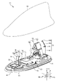
- FIG. 1 is a diagram showing the configuration of a vehicle-mounted antenna device 10 according to a first embodiment of the present invention. 1 is a perspective view of the vehicle-mounted antenna device 10 with the case 22 removed in the zenith direction (upward direction).
- the in-vehicle antenna device 10 is mounted on the roof of a vehicle (not shown), and includes an antenna base 20, a case 22, antennas 30-33, and substrates 40-42.
- the front-rear direction of the vehicle to which the in-vehicle antenna device 10 is mounted is the x-direction
- the left-right direction perpendicular to the x-direction is the y-direction
- the vertical direction perpendicular to the x-direction and the y-direction is the z-direction.
- the front side from the driver's seat of the vehicle is the +x direction
- the left side is the +y direction
- the zenith direction (upward direction) is the +z direction.
- the front-rear, left-right, and up-down directions of the in-vehicle antenna device 10 are the same as the front-rear, left-right, and up-down directions of the vehicle.
- the antenna base 20 is a plate-like member that serves as the bottom surface of the in-vehicle antenna device 10 .
- the antenna base 20 includes, for example, an insulating base made of resin and a metal base 21.
- the metal base 21 is attached to the insulating base with a plurality of screws (not shown).
- the metal base 21 is a plate-shaped member that functions as a ground for the vehicle-mounted antenna device 10 when the vehicle-mounted antenna device 10 is attached to the roof (not shown) of the vehicle.
- the antenna base 20 is configured such that the metal base 21 is directly attached to the insulating base, the present invention is not limited to this.
- the antenna base 20 may be composed only of a metal base or metal plate, or may be attached with another member such as an insulating base or metal plate.
- the antenna base 20 may include an insulating base and a metal plate, or may include an insulating base, a metal base, and a metal plate.
- a structure using a waterproof pad surrounding a metal base without using an insulating base may be used.
- the metal base 21 is formed as an integral metal base to which the substrates 40 to 42 are attached, as shown in FIG.
- the metal base to which the substrates 40-42 are attached may not be an integral metal base.
- the substrates 40 to 42 may be attached to separate metal bases, or the metal base to which the substrates 40 and 42 are attached and the metal base to which the substrate 41 is attached may be separated.
- the separate (divided) metal base may be electrically connected by another metal base or another metal plate, and may be held by an insulating resin base.
- a metal plate may be used instead of the metal base, or a combination of a metal base and a metal plate may be used.
- the case 22 is a member (so-called radome) that covers the antenna base 20 and forms an accommodation space in which the antennas 30 to 33 are accommodated together with the antenna base 20 .
- the case 22 is a case made of a synthetic resin (for example, ABS resin) having electromagnetic wave permeability, and has a shark fin shape that is low in the front and increases in height toward the rear.
- the case 22 is attached to the antenna base 20 so that the opening on the lower side of the case 22 is closed by the antenna base 20 .
- the outer dimensions of the case 23 of this embodiment are, for example, approximately 190 mm to 200 mm in the front-rear direction, approximately 60 mm to 65 mm in the vertical direction, and approximately 70 mm to 75 mm in the horizontal direction.
- a pad which is an elastic member, may be provided between the antenna base 20 and the case 22 .
- Each of the antennas 30 and 31 is an antenna corresponding to radio waves in the V2X frequency band (vertically polarized waves that are linearly polarized waves). Specifically, the antennas 30 and 31 are used when the in-vehicle antenna device 10 transmits radio waves for V2X (for example, 5.9 GHz band) and receives radio waves for V2X by the space diversity method. be done.
- V2X for example, 5.9 GHz band
- the antenna 30 is installed on a board 40 attached to the front portion of the metal base 21 . Although the details will be described later, the antenna 30 is mainly located in front of the in-vehicle antenna device 10 and communicates with another V2X antenna (not shown).
- the antenna 31 is installed on a substrate 41 attached to the rear portion of the metal base 21 .
- the antenna 31 is mainly located behind the in-vehicle antenna device 10 and communicates with another V2X antenna (not shown).
- Antenna 30 is a vertically polarized monopole antenna used for V2X communication.
- the antenna 30 is a rod-shaped metal member that operates as a grounded monopole antenna, and has a feeding point (not shown) at one end on the substrate 40 side. Therefore, the antenna 30 can exchange signals with a signal processing circuit (not shown) via the feeding point and the substrate 40 .
- the length from one end of the antenna 30 of the present embodiment to the other end is a quarter of one wavelength of the V2X frequency band. Since one wavelength of the V2X frequency band is ⁇ (approximately 50 mm), the length of the antenna 30 is ⁇ /4 (approximately 12.5 mm). Further, since the antenna 30 is mounted substantially perpendicular to the front surface of the substrate 40, the height of the antenna 30 from the front surface of the substrate 40 is also ⁇ /4 (approximately 12.5 mm). Become.
- the length (physical length) and distance of the antenna may be described in terms of so-called electrical length using one wavelength ⁇ of the V2X frequency band, such as ⁇ /4.
- the electrical length includes not only a single value but also values that deviate by a predetermined value (for example, a value of 1/32 of ⁇ ). This is because the wavelength is not necessarily represented by a divisible integer, and the electrical length varies depending on various factors such as the material of the object and the environment. Therefore, in this embodiment, for example, ⁇ /4 means approximately ⁇ /4.
- a predetermined electrical length for example, ⁇ /4 may be described as ⁇ /4 or approximately ⁇ /4, but when it is described as simply ⁇ /4 without “substantially” However, approximately ⁇ /4 is included.
- Antenna 31 is a vertically polarized collinear antenna array used for V2X communication.
- the antenna 31 is a metal rod-shaped member attached to the substrate 41 and has a linear portion 60, an annular portion 61, a linear portion 62a, and a bent portion 62b.
- the straight portion 60 has a length of ⁇ /2, and a feeding point (not shown) is provided at one end on the substrate 41 side.
- a linear portion 62 a is provided on the other end side of the linear portion 60 with an annular portion 61 interposed therebetween.
- a linear portion 62 a extends from the annular portion 61 so that the antenna 31 does not come into contact with the case 22 .
- the linear portion 62a extends from the annular portion 61 so as to be inclined by a predetermined angle in the +x direction from the vertical direction.
- a bent portion 62b is provided at the tip of the straight portion 62a in order to reliably prevent contact between the antenna 31 and the case 22.
- the straight portion 62a may extend vertically from the annular portion 61, for example, if the height of the case 22 is sufficiently high, and the bent portion 62b may need to be provided so that the antenna 31 does not contact the case 22. no.
- the length of the tip from the end of the linear portion 62a on the annular portion 61 side to the bent portion 62b in this embodiment is ⁇ /2. Therefore, in the antenna 31, the linear portion 60 having a length of ⁇ /2 and the linear portion 62a and the bent portion 62b having a length of ⁇ /2 are provided on both sides of the annular portion 61. Become. By the way, for example, when the phase of the vertically polarized wave in the linear portion 60 and the phase of the vertically polarized wave in the linear portion 62a and the bent portion 62b are reversed, the gain of the antenna 31 decreases.
- the phase of the vertically polarized wave in the linear portion 60 and the phase of the vertically polarized wave in the linear portion 62a and the bent portion 62b are adjusted so that the gain of the desired frequency band in the antenna 31 is increased.
- An annular portion 61 is provided which is spirally wound for one turn. Therefore, the antenna 31 having such a configuration can increase the gain of radio waves in the frequency band for V2X, for example.
- the antenna 30 is a rod-shaped monopole antenna and the antenna 31 is a collinear antenna array, but they are not limited to this.
- the antennas 30 and 31 may be antennas (including grounded and non-grounded) that support vertical polarization of a desired frequency band, such as dipole antennas and patch antennas. Also good.
- the antennas 30 and 31 are V2X compatible antennas, they may be of other communication standards (for example, Wi-Fi (registered trademark) or Bluetooth (registered trademark)).
- the antenna 32 is, for example, a patch antenna for receiving radio waves in the 1.5 GHz band for the Global Navigation Satellite System (GNSS).
- the antenna 32 of this embodiment is installed on the substrate 42 attached to the metal base 21 and includes a dielectric member 70 and a radiation element 71 .
- the substrate 42 is provided on the substrate 40 side between the substrate 40 provided furthest forward and the substrate 41 provided furthest rearward in the metal base 21 . Therefore, the antenna 32 is provided on the antenna 30 side between the antennas 30 and 31 .
- the dielectric member 70 is made of a dielectric material such as ceramic, and is a substantially square plate-like or box-like member in plan view of the xy plane viewed from the +z direction.
- a conductor functioning as a ground conductor film (or ground conductor plate) is formed on the back surface of the dielectric member 70 . Then, the back surface of the dielectric member 70 is attached to the substrate 42 by, for example, an adhesive (not shown).
- a substantially square conductive radiating element 71 with equal vertical and horizontal lengths is formed on the front surface of the dielectric member 70.
- the "substantially square” also includes a shape in which at least some corners are notched diagonally with respect to the sides, and a shape in which a part of the sides is provided with a notch (concave portion) or protrusion (convex portion).
- the shape of the dielectric member 70 is not limited to a substantially square shape, and may be a quadrilateral shape such as a substantially rectangular shape, a substantially circular shape, a substantially elliptical shape, or the like.
- the radiating element 71 is provided with two feeding points (not shown). Also, although illustration is omitted here for convenience, two feeder lines are connected to each of the two feeder points via two through holes (not shown) passing through the substrate 42 and the dielectric member 70. ing. By distributing power with a phase difference between these feeders, it operates as a circularly polarized antenna.
- the antenna 32 is an antenna for GNSS, it may be an antenna for receiving radio waves of other standards such as satellite digital radio broadcasting service (SDARS: Satellite Digital Audio Radio Service).
- the antenna 33 is, for example, an antenna for receiving radio waves in the DAB (Digital Audio Broadcast) waveband. Specifically, the antenna 33 receives, for example, Band-III (174 MHz to 240 MHz) radio waves.
- the antenna 33 includes a holder 80 , a helical element (hereinafter simply referred to as “coil”) 81 and a capacitive loading element 82 .
- the antenna 33 receives Band-III (174 MHz to 240 MHz) radio waves, but for example, other bands in the DAB (Digital Audio Broadcast) wave band, such as L-Band (1452 MHz to 1492 MHz). It's okay.
- the holder 80 is a resin member that holds the coil 81 and the capacitive loading element 82 and is attached to the metal base 21 .
- a coil 81 is attached to the cylindrical portion of the holder 80 .
- One end of the coil 81 is electrically connected to a circuit board (not shown) provided on the metal base 21 , and the other end of the coil 81 is electrically connected to the capacitive loading element 82 .
- the capacitive loading element 82 is an element that resonates in a desired frequency band together with the coil 81, and is a metal body in which two quadrilaterals attached to the left and right side surfaces of the upper portion of the holder 80 are connected at the bottom. be. In FIG. 1, only the metal body on the right side of the upper portion of the holder 80 is shown for convenience, but a metal body similar to the metal body on the right side is also attached to the holder 80 on the left side. Capacitive loading element 82 also includes a lower metal body (not shown) that connects the left and right metal bodies.
- the “metal body” is formed by processing a metal member.
- a metal member in addition to plate-shaped metal members such as metal plates, three-dimensional metal members other than plate-shaped including.
- the metal body on the right side and the metal body on the left side are connected at the top or formed integrally, and when viewed from the front or rear, an inverted V shape, an inverted U shape, a mountain shape, A three-dimensional shape such as a shape excluding the base of a trapezoid may be used.
- the distance between the rear end of the capacitive loading element 82 and, for example, the tip of the bent portion 62b of the antenna 31 is shorter than ⁇ , which is one wavelength of the V2X frequency band.
- a holder 80 is installed.
- the length of the side on the rear side of the capacitive loading element 82 is, for example, ⁇ /2, but it may be designed to be slightly longer than ⁇ /2. In such a case, the capacitive loading element 82 operates as a reflector for the antenna 31, so the gain of the antenna 31 can be improved.
- the antenna 33 is used as a reflector, the antenna 33 is provided on the antenna 31 side between the antennas 30 and 31 .
- the antennas 30 and 31 for V2X, the antenna 32 for GNSS, and the antenna 33 for DAB are provided.
- the V2X antennas 30 and 31 have the highest operating frequency band of 5 GHz and a short wavelength ⁇ of approximately 50 mm. Therefore, case 22 may affect the directivity of antennas 30 and 31 .
- a model simulating the in-vehicle antenna device 10 is used to verify the influence of the case on the directivity of the antenna. First, referring to the model of FIG. 2, the relationship between the position of the antenna of the vehicle-mounted antenna device and the case is verified.
- FIG. 2A is a diagram showing an example of the case 300 and the base plate 320.
- FIG. FIG. 2B is a diagram for explaining the position of the antenna 310.
- FIG. In FIG. 2B the case 300 is cut along line AA in FIG. 2A so that the antenna 310 inside the case 300 can be seen.
- the longitudinal axis (the axis on the major axis) passing through the geometric center of the elliptical bottom surface of the case 300 is illustrated by a dotted line.
- the case 300 includes an elliptical top surface 300a in a plan view of the xy plane viewed from the +z direction, and a cylindrical member 300b extending in the ⁇ z direction (downward) from the outer circumference of the top surface 300a. .
- the base plate 320 and the top surface 300a are parallel, and the angle formed by the base plate and the cylindrical member 300b is 90°.
- the top surface 300a has a major axis of 220 mm and a minor axis of 110 mm.
- the height of the cylindrical member 300b (the distance from the base plate 320 to the top surface 300a) is 55 mm.
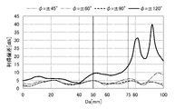
- Antenna 310 is a monopole antenna that can handle vertically polarized waves in the V2X frequency band. Since the antenna 310 is grounded to the ground plane 320, the length of the antenna 310 is ⁇ /4 (approximately 12.5 mm). Further, in the present embodiment, the antenna 310 is mounted on the inside of the cylindrical member 300b on the +x side in the longitudinal axis (the axis on the major axis) passing through the center (geometric center) of the top surface 300a indicated by the dotted line in FIG. 2B. Let the distance to be the distance Da.
- FIGS. 3 and 4 are calculation results showing how the gain (dBi) in the horizontal plane of vertical variation of the antenna 310 varies in all directions.
- an azimuth angle of 0° corresponds to the +x direction (forward direction)
- an azimuth angle of 90° corresponds to the +y direction (leftward direction).
- the "gain deviation” is the difference between the maximum gain and the minimum gain within a predetermined angular range.
- the gain deviation gradually increases from the vicinity of the distance Da of 75 mm, and reaches approximately 31 dBi when the distance Da is 82 mm.
- the distance Da exceeds 82 mm, it fluctuates greatly within a range of approximately 20 dBi to 40 dBi.
- the antennas 30 and 31 receive vertically polarized waves by a so-called diversity method.
- the shape of the +x side end portion of the case 300 shown in FIG. 2 is similar to the shape of the rear side ( ⁇ x side) of the shark fin type case 22 of FIG. 1, for example. Therefore, next, a case similar in shape to the front side (+x side) of the shark fin type case 22 is used, and the same verification as in FIG. 2 is performed.
- FIG. 6A is a diagram showing an example of the case 400 and the main plate 420.
- FIG. FIG. 6B is a diagram for explaining the position of antenna 410.
- the case 400 is cut along line AA in FIG. 6A so that the antenna 410 inside the case 400 can be seen.
- the longitudinal axis (the axis on the major axis) passing through the geometric center of the elliptical bottom surface of the case 400 is illustrated by a dotted line.
- the case 400 includes an elliptical top surface 400a in plan view on the xy plane viewed from the +z direction, and a cylindrical member 400b extending in the ⁇ z direction (downward) from the outer circumference of the top surface 400a.
- the case 400 when the case 400 is placed on the base plate 420 placed on the xy plane, the height of the housing space in the front portion of the case 400 gradually increases, and the base plate 420 A tubular member 400b is formed so as to be parallel to the surface 400a.
- the angle formed by the straight line extending from the farthest portion of the case 400 on the main plate 420 (the portion closest to the +x direction) to the top surface 400a and the main plate 420 is an angle ⁇ (for example, 40°).
- the cylindrical member 400b is formed such that Furthermore, the cylindrical member 400b is arranged so that the angle between the bottom plate 420 and the straight line extending from the rearmost portion (the most ⁇ x direction portion) of the case 400 on the bottom plate 420 to the top surface 400a and the bottom plate 420 is 90°. is formed.
- the top surface 400a has a major axis of 161 mm and a minor axis of 20 mm. Further, the height of the cylindrical member 400b (the distance from the base plate 420 to the top surface 400a) is 55 mm. Further, the major axis and minor axis of the elliptical bottom surface of the case 400 are 220 mm and 45 mm, respectively.
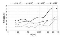
- Antenna 410 is a monopole antenna capable of supporting vertically polarized waves in the V2X frequency band, similar to antenna 310 shown in FIG. Therefore, detailed description is omitted here. Also, here, the distance from the inner tip portion of the cylindrical member 400b on the +x side to the antenna 410 in the longitudinal axis passing through the geometric center of the elliptical bottom surface of the case 400 is defined as the distance Db.
- FIG. 7 is a diagram showing the relationship between the distance Db and the gain deviation.
- the position where the part of the antenna in contact with the case is separated in the horizontal direction by, for example, a distance of 3/2 wavelength (3 ⁇ /2) or less of V2X is defined as the “desired position”.
- a portion of the antenna that contacts the case refers to a portion that virtually contacts the case when the antenna is horizontally moved from its actual installation position.
- FIG. 8 is a diagram for explaining the position of the front antenna 30 in the in-vehicle antenna device 10. As shown in FIG. In order to facilitate understanding, FIG. 8 shows a cross section of the case 22 along a line passing through the center point of the case 22 in the left-right direction and along the x-axis direction.
- the position of the antenna 30 is determined so that part of the antenna 30 is at the desired position described above.
- the antenna 30 (tip P1) is provided at a position spaced rearward by a distance D1 from the position where the tip P1 of the antenna 30 contacts the case 22 .
- the distance D1 is a distance (for example, 5 mm) shorter than approximately 75 mm, which is three-half wavelength (3 ⁇ /2) of V2X.
- the antenna 30 should be placed close to the case 22. However, if the antenna 30 is brought into contact with the case 22, a load is applied to the antenna 30 due to the vibration of the vehicle.
- the state in which the tip portion P1 of the antenna 30 is in contact with the case 22 is indicated by a dotted line for the sake of convenience, but this is an imaginary state.
- FIG. 9 is a diagram for explaining the position of the rear antenna 31 in the in-vehicle antenna device 10. As shown in FIG. Note that FIG. 9 also shows a cross section of the case 22 in the same manner as in FIG.
- the position of the antenna 31 is determined so that part of the antenna 31 is at the desired position described above.
- the antenna 31 An end P2
- the distance D2 is a distance (for example, 5 mm) shorter than approximately 75 mm, which is three-half wavelength (3 ⁇ /2) of V2X.
- the antenna 31 should be placed close to the case 22. However, if the antenna 31 is brought into contact with the case 22, a load is applied to the antenna 31 due to the vibration of the vehicle.
- the dotted line indicates a virtual state in which the end P2 of the straight portion 60 is in contact with the case 22. As shown in FIG.
- FIG. 10 is a diagram showing horizontal directivity of the antennas 30 and 31 installed in the in-vehicle antenna device 10. As shown in FIG. 10 , the solid line indicates the directivity of the antenna 30 and the dotted line indicates the directivity of the antenna 31 . Also, as described above, an azimuth angle of 0° corresponds to the +x direction (forward direction), and an azimuth angle of 90° corresponds to the +y direction (leftward direction).
- FIG. 10 is a simulation result showing horizontal directivity of the antennas 30 and 31 when using an infinite ground plane.
- the gain of slightly less than 10 dBi is obtained for the vertical polarization of the V2X frequency band over the front, rear, left, and right directions of the vehicle-mounted antenna device 10 on the infinite ground plane. can be obtained.
- good directivity can be obtained in the horizontal plane.
- the vehicle-mounted antenna device 10 shown in FIG. 1 is a so-called compound antenna device, and in addition to the V2X antennas 30 and 31, a GNSS antenna 32 and a DAB antenna 33 are provided. there is In such a composite antenna device, individual antennas must be arranged so that unnecessary electrical interference does not occur between the antennas.
- the GNSS antenna 32 and the DAB antenna 33 can be arranged between the antennas 30 and 31 with a long interval.
- the antennas 30 and 31 perform at least one of receiving and transmitting signals in the same frequency band. Between the antennas 30 and 31, antennas (here, antennas 32 and 33) of frequency bands lower than the frequency bands corresponding to the antennas 30 and 31 are arranged. Antennas corresponding to higher frequency bands are more likely to be affected by the case 22 , and conversely, antennas corresponding to lower frequency bands are less likely to be affected by the case 22 . Therefore, in the present embodiment, the antennas 30 and 31 are arranged on the outer side of the vehicle-mounted antenna device 10 , and the antennas 32 and 33 are arranged on the inside of the vehicle-mounted antenna device 10 . By arranging the antennas in this manner, the performance of each antenna can be improved.
- the height of the antenna 30 is lower than the height of the antenna 31. Therefore, by setting the antenna system of the antennas 30 and 31 according to the positions before and after the antennas are arranged in the in-vehicle antenna device 10 and the space inside the case 22, the directivity and gain of the antennas 30 and 31 can be adjusted. can be secured, and the in-vehicle antenna device 10 can be miniaturized.
- the antennas 30 and 31 corresponding to the same frequency band have different antenna systems.
- the antennas 30 and 31 are not limited to different antenna systems, and may be of the same antenna system depending on design requirements. In this manner, when a plurality of antennas are arranged in the vehicle-mounted antenna device 10, a combination of antennas of the same antenna system may be included, or antennas of different antenna systems may be used.
- the antennas 30 and 31 are arranged substantially in the center of the vehicle-mounted antenna device 10 in the width direction (Y direction). Therefore, the directivity of the antennas 30 and 31 can be symmetrical with respect to the X-axis, and adjustment and control to provide directivity in the front-rear direction (X direction) is facilitated.
- the antenna 32 is arranged so that the height of the top surface is lower than the top end of the antenna 30 . In this case, the electrical properties of the antenna 30 are improved. However, the antenna 32 may be arranged so that the top surface is higher than the top end of the antenna 30 . In this case, the electrical properties of the antenna 32 are improved. That is, in this embodiment, the height of the antennas arranged in the vehicle-mounted antenna device 10 can be selected depending on the application of design. As a result, the characteristics of the antenna arranged in the vehicle-mounted antenna device 10 can be ensured without impairing the design of the vehicle-mounted antenna device 10, and miniaturization is also possible.
- the antennas 30, 31 and 32 are installed on different substrates. However, at least two of the antennas 30, 31 and 32 are They may be installed on the same substrate. As a result, it is possible to improve the assemblability of the antenna.
- the antenna 30 corresponds to the "first antenna” and the antenna 31 corresponds to the "second antenna”. Also, for example, the antenna 32 corresponds to a "third antenna”.
- the tip portion P1 of the antenna 30 corresponds to "at least part of the first antenna", and the distance D1 corresponds to "a predetermined distance".
- the +x direction corresponds to the "first direction”
- the -x direction corresponds to the "second direction opposite to the first direction”.
- the end P2 of the linear portion 60 of the antenna 31 corresponds to "at least a part of the second antenna", and the distance D2 corresponds to "a predetermined distance”.
- a position separated by a distance D1 from the position where the tip P1 of the antenna 30 contacts the case 22 corresponds to the "first position”.
- a position separated by a distance D2 from the position where the end P2 of the antenna 31 contacts the case 22 corresponds to the "second position”.
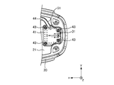
- FIG. 11 is a diagram for explaining the configuration of the vehicle-mounted antenna device 11 of the second embodiment.
- FIG. 11 depicts a state in which the case 22 is removed in the zenith direction (upward direction).
- the vehicle-mounted antenna device 11 includes an antenna 34 and parasitic elements 35, 36a to 36c instead of the antenna 30 of the vehicle-mounted antenna device 10 of FIG. Therefore, the antenna 34 and the parasitic elements 35, 36a to 36c will be described here.
- the three parasitic elements 36a to 36c may be collectively referred to as a parasitic element 36 hereinafter.
- Antenna 34 is a vertically polarized monopole antenna used for V2X communication, similar to antenna 30 .
- the antenna 34 is a rod-shaped metal member that operates as a grounded monopole antenna, and has a feeding point (not shown) at one end on the substrate 40 side. Therefore, the antenna 30 can exchange signals with a signal processing circuit (not shown) via the feeding point and the substrate 40 .
- the length from one end of the antenna 34 of this embodiment to the other end is half of one wavelength of the V2X frequency band. Therefore, the length of the antenna 34 is ⁇ /2 (approximately 25 mm). Further, since the antenna 34 is mounted substantially perpendicular to the front surface of the substrate 40, the height of the antenna 34 from the front surface of the substrate 40 is also ⁇ /2 (approximately 25 mm).
- the position of the antenna 34 is determined so that part of the antenna 34 is at the desired position described above.
- the antenna 34 (tip P3) is provided at a position spaced backward by a distance D3 from the position where the tip P3 of the antenna 34 contacts the case 22 .
- the distance D3 is a distance (for example, 5 mm) shorter than approximately 75 mm, which is three-half wavelength (3 ⁇ /2) of V2X.
- the parasitic elements 35 and 36 are elements for improving directivity while increasing the gain in front of the antenna 34 (+x direction).
- the parasitic element 35 is a bar-shaped metal body that functions as a so-called director with respect to the antenna 34 and is installed in front of the antenna 34 .
- the parasitic element 35 is installed on the substrate 40 in a non-grounded state.
- the length of the parasitic element 35 is less than or equal to the length of the antenna 34 ( ⁇ /2).
- Each of the parasitic elements 36a to 36c is a bar-shaped metal body that functions as a so-called reflector with respect to the antenna 34, and is installed behind the antenna 34. Therefore, parasitic elements 36 a - 36 c are provided between antenna 30 and antenna 32 . In addition, the parasitic elements 36a to 36c are installed on the metal base 21 in a non-grounded state. The length of each of the parasitic elements 36a to 36c is equal to or longer than the length of the antenna 34 (approximately ⁇ /2).
- the tips of the parasitic elements 36a to 36c of the present embodiment are bent in order to prevent the parasitic elements 36a to 36c from coming into contact with the case 22.
- FIG. therefore, for example, when the housing space of the case 22 is sufficiently high, the parasitic elements 36a to 36c may be linear members.
- the manner in which the parasitic elements 36a to 36c are bent may be other than the case shown in FIG.
- the tips of the parasitic elements 36a and 36c are bent in the -x direction (backward), and the tip of the parasitic element 36b is bent in the +x direction (forward). is bent.
- the parasitic elements 36 that are bent in different directions are mixed.
- all of the parasitic elements 36a to 36c may be bent in the same direction.
- each of the parasitic elements 36a to 36c is bent at one point (upper end). However, for example, it may be bent below each of the parasitic elements 36a to 36c, or may be bent at a plurality of positions. Furthermore, the angle at which each of the parasitic elements 36a to 36c is bent may not be the 90° direction shown in FIG. This can further prevent the parasitic elements 36a to 36c from coming into contact with the case 22, and the in-vehicle antenna device 11 can be further miniaturized.
- the parasitic elements 35 and 36 of this embodiment are arranged in an imaginary circle (hereinafter referred to as “circle C ) is preferably installed in the inner range of the Specifically, the parasitic element 35 is installed in the half range on the +x side within the circle C, and the parasitic element 36 is installed in the half range on the ⁇ x side within the circle C. preferably.
- the horizontal directivity of the antenna 30 can be improved.
- both the parasitic elements 35 and 36 are provided in the in-vehicle antenna device 11, only one of them may be provided. Also, although three parasitic elements 36 operating as reflectors are provided, at least one parasitic element 36 may be provided.
- the length of the parasitic element 35 is ⁇ /4 or less, and when the parasitic element 36 is grounded, the length of the parasitic element 36 is ⁇ /4 or more. becomes.
- the length of each of the parasitic elements 35 and 36 should be set so that they can appropriately operate as a director and a reflector with respect to the antenna 34 .
- FIG. 13 is a diagram showing a simulation result of the directivity of the horizontal plane of the antennas 31 and 34 installed in the in-vehicle antenna device 11 of the infinite ground plane.
- the solid line indicates the directivity of the antenna 34 and the dotted line indicates the directivity of the antenna 31 .
- an azimuth angle of 0° corresponds to the +x direction (forward direction)
- an azimuth angle of 90° corresponds to the +y direction (leftward direction).
- the vehicle-mounted antenna device 11 includes the parasitic element 35 that operates as a director and the parasitic element 36 that operates as a reflector. Therefore, in the in-vehicle antenna device 11, the gain in front of the antenna 34 (+x direction) is particularly increased, and the directivity is also improved.
- FIG. 14 is a diagram showing the horizontal plane gain of the antenna 34 in each of the vehicle-mounted antenna device 11 and the vehicle-mounted antenna device X (described later).
- FIG. 15 is a diagram showing the horizontal plane gain of the antenna 31 in each of the vehicle-mounted antenna device 11 and the vehicle-mounted antenna device X.
- the “vehicle-mounted antenna device X” is a comparison target device in which the GNSS antenna 32 and the DAB antenna 33 are not provided in the configuration of the vehicle-mounted antenna device 11 of FIG. 11 . .
- the difference between the vehicle-mounted antenna device 11 and the vehicle-mounted antenna device X is only the antenna 32 for GNSS and the antenna 33 for DAB. I don't.
- the antenna 31 is an antenna that mainly supports vertical polarized waves in the direction of the -x side (within a range of ⁇ 120° around an azimuth angle of 180°). Therefore, even if the gain in the azimuth angle range of 30° to 330° among the gains of the antenna 31 is reduced, the characteristics of the antenna 31 are not affected.
- each of the antennas 31 and 34 is arranged at a position close to the case 22, thereby preventing the antennas 31 and 34 from being affected by other antennas. , good directivity can be obtained.
- the antennas 34 and 31 perform at least one of receiving and transmitting signals in the same frequency band. Between the antenna 34 and the antenna 31, an antenna (here, the antenna 32 and the antenna 33) of a frequency band lower than the frequency band to which the antennas 34 and 31 correspond is arranged. Antennas corresponding to higher frequency bands are more likely to be affected by the case 22 , and conversely, antennas corresponding to lower frequency bands are less likely to be affected by the case 22 . Therefore, in this embodiment, the antennas 34 and 31 are arranged on the outer side of the vehicle-mounted antenna device 11 , and the antennas 32 and 33 are arranged on the inside of the vehicle-mounted antenna device 11 . By arranging the antennas in this manner, the performance of each antenna can be improved.
- the height of the antenna 34 is lower than the height of the antenna 31. Therefore, by setting the antenna system of the antennas 34 and 31 according to the positions before and after the antennas are arranged in the in-vehicle antenna device 11 and the space inside the case 22, the directivity and gain of the antennas 34 and 31 can be adjusted. can be ensured, and the in-vehicle antenna device 11 can be miniaturized.
- the antennas 34 and 31 corresponding to the same frequency band have different antenna systems.
- the antennas 34 and 31 are not limited to different antenna systems, and may be of the same antenna system depending on design requirements. In this manner, when a plurality of antennas are arranged in the vehicle-mounted antenna device 11, a combination of antennas of the same antenna system may be included, or antennas of different antenna systems may be used.
- the antennas 34 and 31 are arranged substantially in the center of the vehicle-mounted antenna device 11 in the width direction (Y direction). Therefore, the directivity of the antennas 34 and 31 can be symmetrical with respect to the X-axis, and adjustment and control to provide directivity in the front-rear direction (X-direction) is facilitated.
- the antenna 32 is arranged so that the height of the top surface is lower than the top end of the antenna 34 . In this case, the electrical properties of the antenna 34 are improved. However, the antenna 32 may be arranged so that the top surface is higher than the top end of the antenna 34 . In this case, the electrical properties of the antenna 32 are improved. That is, in the present embodiment, the height of the antennas arranged in the vehicle-mounted antenna device 11 can be selected depending on the purpose of design. As a result, the characteristics of the antenna arranged in the vehicle-mounted antenna device 11 can be ensured without impairing the design of the vehicle-mounted antenna device 11, and miniaturization is also possible.
- the antennas 34, 31 and 32 are installed on different substrates. However, at least two of the antennas 34, 31 and 32 are They may be installed on the same substrate. As a result, it is possible to improve the assemblability of the antenna.
- the antenna 34 corresponds to the "first antenna”. Further, for example, the corner P3 of the antenna 34 corresponds to "at least part of the first antenna”, and the distance D3 corresponds to "predetermined distance”.
- a position separated by a distance D3 from the position where the corner P3 of the antenna 34 contacts the case 22 corresponds to the "first position".
- FIG. 16 is a diagram for explaining the configuration of the vehicle-mounted antenna device 12 of the third embodiment.
- the in-vehicle antenna device 12 is provided with an antenna 37 instead of the antenna 30 in the in-vehicle antenna device 10 of FIG.
- the configuration other than the antenna 37 is the same as that of the vehicle-mounted antenna device 10, so the antenna 37 will be described here.
- the antenna 37 is a patch antenna that supports vertically polarized waves in the V2X frequency band, and includes a patch element 37a and a ground conductor plate 37b.
- the patch element 37a is a member formed by bending a metal plate so as to have a convex shape in the +x direction.
- the patch element 37a has a +x-side top portion 38 having a predetermined width (length in the y-axis direction), and two slopes bent in the ⁇ x direction side from the left and right sides of the top portion 38, respectively. a portion 39;
- the ground conductor plate 37b is a member formed by bending a metal plate so as to be convex in the +x direction. Further, the ground conductor plate 37b of this embodiment is electrically connected to the metal base 21 so as to function as a ground.
- a synthetic resin dielectric (not shown), for example, is sandwiched between the patch element 37a and the ground conductor plate 37b so as to fill the gap between them. Also, the dielectric is adhered to each of the patch element 37a and the ground conductor plate 37b with an insulating tape (not shown). Therefore, the patch element 37a is fixed to the ground conductor plate 37b via the dielectric. Even when such an antenna 37 is used, it is possible to receive vertically polarized waves in the V2X frequency band.
- FIG. 17 is a diagram for explaining the position of the front antenna 37 in the in-vehicle antenna device 12. As shown in FIG. 17 also shows a cross section of the case 22 in the same manner as in FIG. 8 described above.
- the position of the antenna 37 is determined so that part of the antenna 37 is at the desired position described above.
- the antenna 37 (corner P4 ) is provided.
- the distance D4 is a distance (for example, 5 mm) shorter than approximately 75 mm, which is three-half wavelength (3 ⁇ /2) of V2X.
- FIG. 17 shows a virtual state in which the corner P3 of the ground conductor plate 37b of the antenna 37 is in contact with the case 22 by dotted lines.
- the in-vehicle antenna device 12 can obtain good directivity (in particular, forward directivity) in the V2X frequency band.
- the antenna 37 corresponds to the "first antenna”. Further, for example, the corner P4 of the antenna 37 corresponds to "at least part of the first antenna”, and the distance D4 corresponds to "predetermined distance”.
- a position separated by a distance D4 from the position where the corner P4 of the antenna 37 contacts the case 22 corresponds to the "first position".
- FIG. 18 is a diagram for explaining the configuration of the vehicle-mounted antenna device 13 of the fourth embodiment.
- the in-vehicle antenna device 13 is housed, for example, in a cavity between a roof panel (not shown) of the vehicle and a roof lining on the ceiling surface of the vehicle interior.
- the vehicle-mounted antenna device 13 is a compound antenna device including a plurality of antennas operating in different frequency bands, and includes a metal base 500, a case 501, and antennas 510-514.
- the antenna 512 is a generic term for the antennas 512a to 512d
- the antenna 513 is a generic term for the antennas 513a and 513b
- the antenna 514 is a general term for the antennas 514a and 514b.
- the metal base 500 is a substantially rectangular metal plate used as a common ground for the antennas 510 to 514, and is installed on the roof lining of the vehicle. Also, the metal base 500 is a thin plate extending in the front, rear, left, and right directions.
- the case 501 is a box-shaped member, and one of its six faces is open on the lower side. Further, since the case 501 is made of an insulating resin, radio waves can pass through the case 501 . Then, the case 501 is attached to the metal base 500 so that the lower opening of the case 501 is closed by the metal base 500 . Therefore, the antennas 510 to 514 are accommodated in the space (accommodation space) inside the case 501 .
- Antenna 510 is, for example, a patch antenna compatible with the SDARS system, and receives left-hand circularly polarized waves in the 2.3 GHz band. Antenna 510 is installed near the center of metal base 500 .
- Antenna 511 is, for example, a planar antenna compatible with GNSS, and receives radio waves in the 1.5 GHz band from artificial satellites. Antenna 511 is installed behind antenna 510 ( ⁇ x direction).
- Antenna 512 is an antenna that supports vertically polarized waves in the V2X frequency band, and is the same as antenna 30 of vehicle-mounted antenna device 10 in FIG.
- Each of antennas 512 a - 512 d are arranged around antenna 510 .
- antennas 512a and 512b are arranged on the front and rear sides of antenna 510, respectively.
- antennas 512c and 512d are arranged on the left and right sides of antenna 510, respectively.
- the antenna 512a mainly corresponds to vertical polarization from the front (+x direction), and the antenna 512b mainly corresponds to vertical polarization from the rear (-x direction).
- the antenna 512c mainly corresponds to vertically polarized waves from the left side (+y direction), and the antenna 512d mainly corresponds to vertically polarized waves from the right side ( ⁇ y direction). Since the vehicle-mounted antenna device 13 has a plurality of antennas 512a to 512d with different directivities, it can receive desired radio waves in a diversity manner. Details of the installation positions of the antennas 510a to 510d will be described later.
- Antennas 513a and 513b are, for example, telematics antennas compatible with the fifth generation mobile communication system. Antennas 513a and 513b transmit and receive radio waves in the Sub-6 band defined by the standards of the fifth generation mobile communication system.
- Antennas 514a and 514b are, for example, telematics antennas compatible with LTE (Long Term Evolution) and 5th generation mobile communication systems.
- Antenna 514 transmits and receives radio waves in the 700 MHz to 2.7 GHz band defined by the LTE standard. Further, the antenna 514 also transmits and receives radio waves in the Sub-6 band defined by the fifth generation mobile communication system standards, that is, frequency bands from 3.6 GHz to less than 6 GHz.
- the applicable communication standards and frequency bands for the antennas 510 to 514 are not limited to those described above, and other communication standards and frequency bands may be used.
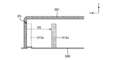
- FIG. 19 is a diagram for explaining the installation position of the antenna 512a. Specifically, FIG. 19 is an enlarged view of the vicinity of the installation position of the antenna 512a in the cross section of the in-vehicle antenna device 13 taken along line AA in FIG.
- the position of the antenna 512a is determined so that part of the antenna 512a is at the desired position described above.
- the antenna 512a (tip P5) is provided at a position spaced backward by a distance D5 from the position where the tip P5 of the rod-shaped antenna 512a contacts the case 501.
- the distance D5 is a distance (for example, 5 mm) shorter than approximately 75 mm, which is three-half wavelength (3 ⁇ /2) of V2X.
- a virtual state in which the tip portion P5 of the antenna 512a is in contact with the case 501 is indicated by dotted lines.
- the in-vehicle antenna device 13 can improve the directivity in the four directions of front, rear, left, and right in the V2X frequency band.
- the in-vehicle antenna device 13 of FIG. 18 is provided with four V2X antennas 512a to 512d, the present invention is not limited to this.
- antennas for V2X only two front-rear antennas 512a and 512b may be provided, or only two left-right antennas 512c and 512d may be provided. Even in such a case, the directivity of the provided antenna can be improved.
- the antenna 512a corresponds to the "first antenna” and the antenna 512b corresponds to the "second antenna”. Also, for example, the antenna 510 corresponds to a "third antenna”.
- the tip portion P4 of the antenna 512a corresponds to "at least part of the first antenna”, and the distance D4 corresponds to "predetermined distance”.
- the +x direction corresponds to the "first direction”
- the -x direction corresponds to the "second direction opposite to the first direction”.
- a position separated by a distance D4 from the position where the tip P4 of the antenna 512a contacts the case 501 corresponds to the "first position”.
- the position corresponding to the tip of the antenna 512b corresponds to the "second position”.
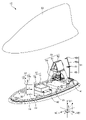
- FIG. 20 is a diagram showing the configuration of a vehicle-mounted antenna device 14 according to a fifth embodiment of the present invention.
- the vehicle-mounted antenna apparatus 14 includes only an antenna 30 as an antenna corresponding to radio waves in the V2X frequency band.
- the in-vehicle antenna device 14 does not have the antenna 31 and the substrate 41 of the in-vehicle antenna device 10 of the first embodiment.
- the vehicle-mounted antenna device 14 has the same configuration as the vehicle-mounted antenna device 10 except that the antenna 31 and the substrate 41 are not provided.
- 20 is also a perspective view of the vehicle-mounted antenna device 14 with the case 22 removed in the zenith direction (upward direction), as in FIG.
- FIG. 21 is a diagram showing horizontal directivity of the antenna 30 installed in the vehicle-mounted antenna device 14 . Also, as described above, an azimuth angle of 0° corresponds to the +x direction (forward direction), and an azimuth angle of 90° corresponds to the +y direction (leftward direction).
- FIG. 21 is a simulation result showing horizontal directivity of the antenna 30 when using an infinite ground plane. As shown in FIG. 21 , in this embodiment, although there are some exceptions, the gain of slightly less than 10 dBi is obtained for the vertically polarized wave of the V2X frequency band across the front, back, left, and right directions of the in-vehicle antenna device 10 on the infinite ground plane. can be obtained. Thus, when the antenna 30 is used, good directivity can be obtained in the horizontal plane.
- the vehicle-mounted antenna device 14 of the fifth embodiment described above includes only the front antenna 30 with respect to antennas corresponding to radio waves in the V2X frequency band.
- the in-vehicle antenna device may include only the rear antenna 31 as an antenna corresponding to radio waves in the V2X frequency band. Even in this case, by setting the position of the antenna 31 at a desired position, it is possible to reduce the gain deviation in a wide angle range and improve the directivity.
- FIG. 22 is a perspective view showing the periphery of the substrate 41 of the in-vehicle antenna device 10.
- FIG. 22A shows a perspective view in which the substrate 41 and the like are attached to the metal base 21, and
- FIG. 22B shows an exploded perspective view in which the substrate 41 and the like are removed from the metal base 21.
- FIG. 23 is a plan view showing the periphery of the substrate 41 of the in-vehicle antenna device 10. As shown in FIG.
- the antenna 31 of the vehicle-mounted antenna device 10 described above is installed on a substrate 41 attached to the rear portion of the metal base 21 .
- the antenna 31 is electrically connected to the substrate 41 at a feeder (not shown).
- the antenna 31 is connected to the coaxial cable 44 shown in FIG. 22B through a matching circuit (not shown) mounted on the substrate 41.
- Circuit elements and electronic parts other than the matching circuit may be mounted on the substrate 41 .
- the outer periphery of the substrate 41 on the matching circuit side (lower side) is electrically connected to the ground on the antenna 31 side through through holes, via holes, or the like.
- the outer periphery of the substrate 41 on the side of the matching circuit is subjected to conductive surface treatment such as solder liber or gold plating.
- the metal base 21 is formed with a receiving portion 49 and a cable accommodating portion 51, as shown in FIGS. 22A to 23.
- FIG. 22A to 23 the metal base 21 is formed with a receiving portion 49 and a cable accommodating portion 51, as shown in FIGS. 22A to 23.
- the receiving portion 49 is a receiving structure (recess) for the substrate 41 formed so as to come into contact with the outer periphery of the substrate 41 on the matching circuit side (lower side).
- the substrate 41 is held under pressure by assembling the substrate 41 to the metal base 21 using screws 43 .
- the receiving portion 49 of the metal base 21 and the outer circumference of the substrate 41 on the matching circuit side come into contact with each other.
- the ground on the antenna 31 side and the metal base 21 can be electrically connected over the entire circumference of the substrate 41 on the matching circuit side.
- the receiving portion 49 is formed so that the height of the substrate 41 and the height of the metal base 21 are the same when the substrate 41 is assembled to the metal base 21 . As a result, it is possible to suppress the generation of radiation wave sources generated at the edge of the substrate 41 and reduce the influence of the shape of the substrate 41 on the electrical characteristics of the antenna 31 .
- the contact portion and the metal base 21 can be electrically connected.
- the interval between the screws 43 is preferably less than half the wavelength of the frequency used by the antenna 31 .
- the cable accommodating portion 51 is a concave portion in which the coaxial cable 44 connected to the substrate 41 is accommodated, as shown in FIGS. 22B and 23 .
- the coaxial cable 44 is held by the metal base 21 by being housed in the cable housing portion 51 . This improves the retention of the coaxial cable 44 .
- the coaxial cable 44 is positioned below the substrate 41 .
- the coaxial cable 44 can be may be located below the top surface of the As a result, it is possible to suppress the decrease in the gain of the antenna 31 and the influence on the directivity due to the leakage current of the coaxial cable 44 .
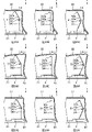
- FIG. 24 is a diagram for explaining another example of the antenna 31 and the case 22.
- FIG. 24A to 24C show examples in which the case 22 having the first case shape is combined with the antennas 31 having the first to third antenna shapes.
- 24D to 24F show examples in which the case 22 of the second case shape is combined with the antennas 31 of the first to third antenna shapes.
- 24G to 24I show examples in which the case 22 having the third case shape is combined with the antennas 31 having the first to third antenna shapes.
- the antenna 31 shown in FIG. 9 has a shape (hereinafter referred to as “first antenna shape”) having a linear portion 62a that inclines in the +x direction as it goes upward (+z direction) from the annular portion 61 .
- first antenna shape a shape having a linear portion 62a that inclines in the +x direction as it goes upward (+z direction) from the annular portion 61 .
- second antenna shape a linear shape along the z-direction
- the antenna 31 has a linear portion 60 that inclines in the +x direction as it goes downward (-z direction) and a linear portion 62a that inclines in the +x direction as it goes upward (+z direction) with the annular portion 61 as a boundary. It may have a shape (hereinafter referred to as “third antenna shape”).
- the linear portion 62 a connected to one end of the annular portion 61 is inclined in the +x direction as it goes upward (+z direction) from the connection point with the annular portion 61 .
- the straight portion 60 connected to the other end of the annular portion 61 is inclined in the +x direction as it goes downward (-z direction) from the connection point with the annular portion 61 .
- one end and the other end of the annular portion 61 are closest to the case 22 .
- the case 22 shown in FIG. 9 has a shape having an inner wall along the z direction (hereinafter referred to as "first case shape”).
- first case shape a shape having an inner wall along the z direction
- second case shape a shape having an inner wall that inclines in the ⁇ x direction as it goes upward (+z direction).
- the case 22 shown in FIG. 9 has a shape in which the wall on the side of the antenna base 20 has a bulge that protrudes inward (to the side of the antenna 31).
- the shape of the walls of case 22 may be more straight than the first case shape, as shown in FIGS. 24G-24I.
- the antenna 31 may have a shape having a linear portion 62a inclined in the ⁇ x direction as it goes upward (+z direction) from the annular portion 61. .
- the antenna 31 has a linear portion 62a inclined in the -x direction side upward (+z direction) with the annular portion 61 as a boundary, and a linear portion 60 inclined in the -x direction side downward (-z direction). It may be a shape having and.
- FIG. 25 is a diagram for explaining another example of the antenna 34.
- FIG. 25A shows an example of an antenna 34 having a first antenna shape
- FIG. 25B shows an example of an antenna 34 having a second antenna shape
- FIG. 25C shows an example of an antenna 34 having a third antenna shape.
- the antenna 34 shown in FIGS. 11 and 12 was attached so as to be substantially vertical on the front surface of the substrate 40 .
- the shape of the antenna 34 may be other than those shown in FIGS.
- the tip of the antenna 34 may be bent along the case 22 as shown in FIGS. 25A and 25B. Note that the tip of the first antenna-shaped antenna 34 shown in FIG. 25A is bent in the +x direction, and the tip of the second antenna-shaped antenna 34 shown in FIG. 25B is bent in the -x direction. ing.
- the angle at which the antenna 34 is bent does not have to be the angle along the case 22 as shown in FIGS. 25A and 25B.
- the angle at which the antenna 34 is bent may be an acute angle, a right angle, or an obtuse angle as long as the antenna 34 does not come into contact with the case 22 or other antennas.
- FIG. 26 is a perspective view showing the periphery of the substrate 40 of the in-vehicle antenna device 11. As shown in FIG. 26A shows a perspective view in which the substrate 40 and the like are attached to the metal base 21, and FIG. 26B shows an exploded perspective view in which the substrate 40 and the like are removed from the metal base 21.
- FIG. FIG. 27 is a plan view showing the periphery of the substrate 40 of the in-vehicle antenna device 11. As shown in FIG.
- the antenna 34 of the vehicle-mounted antenna device 11 described above is installed on a substrate 40 attached to the front portion of the metal base 21 .
- the antenna 34 is electrically connected to the substrate 40 at a feeder (not shown).
- the antenna 34 is connected to the coaxial cable 46 shown in FIG. 26B via a matching circuit (not shown) mounted on the substrate 40 .
- Circuit elements and electronic components other than the matching circuit may be mounted on the substrate 40 .
- the outer circumference of the substrate 40 on the matching circuit side (lower side) is electrically connected to the ground on the antenna 34 side through through holes, via holes, or the like.
- the outer periphery of the substrate 40 on the side of the matching circuit is subjected to a conductive surface treatment such as solder liber or gold plating.
- the metal base 21 is formed with a receiving portion 50 and a cable accommodating portion 52, as shown in FIGS. 26B and 27.
- FIG. 26B the metal base 21 is formed with a receiving portion 50 and a cable accommodating portion 52, as shown in FIGS. 26B and 27.
- FIG. 26B the metal base 21 is formed with a receiving portion 50 and a cable accommodating portion 52, as shown in FIGS. 26B and 27.
- FIG. 26B the metal base 21 is formed with a receiving portion 50 and a cable accommodating portion 52, as shown in FIGS. 26B and 27.
- the receiving portion 50 is a receiving structure (recess) of the substrate 40 formed so as to come into contact with the outer periphery of the substrate 40 on the matching circuit side (lower side), as shown in FIG. 26B.
- the substrate 40 is held under pressure by assembling the substrate 40 to the metal base 21 using screws 45 .
- the receiving portion 50 of the metal base 21 and the outer circumference of the substrate 40 on the matching circuit side come into contact with each other.
- the ground on the antenna 34 side and the metal base 21 can be electrically connected over the entire circumference of the substrate 40 on the matching circuit side.
- the receiving portion 50 is formed so that the height of the substrate 40 and the height of the metal base 21 are the same when the substrate 40 is attached to the metal base 21 . As a result, it is possible to suppress the generation of the radiation wave source generated at the edge of the substrate 40 and reduce the influence of the shape of the substrate 40 on the electrical characteristics of the antenna 34 .
- the contact portion and the metal base 21 can be electrically connected.
- the interval between the screws 45 is preferably less than half the wavelength of the frequency used by the antenna 34 .
- the cable accommodating portion 52 is a concave portion in which the coaxial cable 46 connected to the substrate 40 is accommodated, as shown in FIGS. 26B and 27 .
- the coaxial cable 46 is held by the metal base 21 by being housed in the cable housing portion 52 . This improves the retention of the coaxial cable 46 .
- the coaxial cable 46 is positioned below the substrate 40 .
- the coaxial cable 46 can be may be located below the top surface of the As a result, it is possible to suppress the decrease in the gain of the antenna 34 and the influence on the directivity due to the leakage current of the coaxial cable 46 .
- the parasitic elements 35 and 36 may be held by a holder 47 as shown in FIGS. 26A and 26B.
- a holder 47 holding the parasitic elements 35 and 36 is made of resin, for example, and assembled to the metal base 21 with screws 48 . Thereby, the parasitic elements 35 and 36 can be arranged in the air.
- the integrally formed holder 47 holds both the parasitic element 35 and the parasitic element 36 . As a result, it is possible to improve the assemblability of the in-vehicle antenna device 11 .
- the holder holding the parasitic element 35 and the holder holding the parasitic element 36 may be formed separately.
- the holder 47 does not cover all of the parasitic elements 35 and 36, as shown in FIGS. 26A and 26B, so as to cover at least a portion of them. As a result, it is possible to reduce the contact area between the conductor portions of the parasitic elements 35 and 36 and the resin of the holder 47, thereby suppressing a decrease in the gain of the antenna 34 and a change in directivity. Furthermore, by not covering all the parasitic elements 35 and 36, the resin material used for the holder 47 can be reduced, and the cost can be suppressed.
- the parasitic elements 35 and 36 are held by the holder 47 so that the lower ends of the parasitic elements 35 and 36 abut against the holder 47 . Thereby, the parasitic elements 35 and 36 can be arranged in the air. That is, it is possible to avoid the parasitic elements 35 and 36 from contacting the metal base 21 and the substrate 40 .
- the parasitic elements 35 and 36 can be configured to be inserted into the holder 47 from above, so that the ease of assembly of the in-vehicle antenna device 11 can be improved.
- At least part of the holder 47 is arranged between the antenna 34 and the case 22 .
- the dielectric constants of the holder 47 and the case 22 may be the same or different.
- the holder 47 is made of a material having a low dielectric constant with respect to the case 22, it is possible to suppress the decrease in the gain of the antenna 34 and the influence on the directivity.
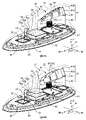
- FIG. 28 is a perspective view of the in-vehicle antenna device 15.
- FIG. 28A is a perspective view showing the appearance of the vehicle-mounted antenna device 15 to which the case 22 is attached
- FIG. 28B is a cross-sectional perspective view showing the inside of the vehicle-mounted antenna device 15 with a part of the case 22 removed. be.
- the above-described vehicle-mounted antenna device 14 shown in FIG. 20 has only an antenna 30 in front of the vehicle-mounted antenna device 14 with respect to antennas corresponding to radio waves in the V2X frequency band.
- the vehicle-mounted antenna device 15 shown in FIGS. 28A and 28B may include only the antenna 31 at the rear of the vehicle-mounted antenna device 15 with respect to antennas corresponding to radio waves in the V2X frequency band.
- features of the in-vehicle antenna device 15 that are different from those of the in-vehicle antenna device 14 will be described.
- the vehicle-mounted antenna device 14 shown in FIG. 20 described above includes, in addition to the antenna 30, an antenna 32 compatible with radio waves in the GNSS band and an antenna 33 compatible with radio waves in the DAB wave band.
- two antennas 32 are arranged vertically.
- a configuration in which two antennas 32 are arranged vertically is sometimes called a multistage patch antenna, a multilayer patch antenna, or a laminated patch antenna.
- the frequency band to which the first patch antenna corresponds can be made different from the frequency band to which the second patch antenna corresponds.
- one patch antenna can support a plurality of frequency bands.
- the antenna 32 can also handle radio waves in a frequency band different from the 1.5 GHz band in the GNSS band.
- the antenna 32 may have a parasitic element.
- the antenna 32 of this embodiment as shown in FIG. 28B, two parasitic elements 72 are arranged above the radiating element 71 of the upper antenna 32 .
- the parasitic element 72 may be held by a holding member (not shown) surrounding the radiating element 71 .
- the antenna 32 can improve the axial ratio especially at low elevation angles.
- the case 22 can be designed to be close to the antenna 31, as shown in FIGS. 28A and 28B.
- the case 22 in the in-vehicle antenna device 15 , the case 22 can be designed along the shape of the antenna 31 . As a result, the influence of the case 22 on the antenna 31 can be further reduced.
- the antenna 31 has a circuit 63 that suppresses signals in the frequency band to which the antenna 32 corresponds, as shown in FIG. 29, which will be described later.
- the circuit 63 is a filter that suppresses signals in the GNSS band to which the antenna 32 corresponds. In other words, the circuit 63 suppresses signals in an undesired frequency band among the frequency bands of radio waves to which the antenna 31 corresponds.
- the circuit 63 is not limited to a filter, and may be a substrate pattern or the like having frequency characteristics that suppress signals in the GNSS band.
- the circuit 63 may be a lumped constant circuit, a distributed constant circuit, or a composite circuit of a lumped constant and a distributed constant.
- the antenna 31 may not have the circuit 63 .
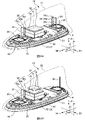
- FIG. 29 is an explanatory diagram of the separation distance Dgv between the antennas 31 and 32.
- the separation distance Dgv is the horizontal separation distance between the antennas 31 and 32 in the side view of the model as shown in FIG.
- the maximum axial ratio of the antenna 32 is calculated for both the model in which the antenna 31 does not have the circuit 63 and the model in which the antenna 31 has the circuit 63 when the separation distance Dgv is varied.
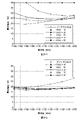
- FIG. 30 is a graph showing an example of the maximum axial ratio at an elevation angle of 90° when the separation distance Dgv is changed.
- 30A is a graph when the antenna 31 does not have the circuit 63
- FIG. 30B is a graph when the antenna 31 has the circuit 63.
- FIG. 31 is a graph showing an example of the maximum axial ratio at an elevation angle of 10° when the separation distance Dgv is changed.
- 31A is a graph when the antenna 31 does not have the circuit 63
- FIG. 31B is a graph when the antenna 31 has the circuit 63.
- the calculation results of the maximum axial ratio of the antenna 32 when the separation distance Dgv between the antenna 31 and the antenna 32 is changed to 10 mm, 30 mm, 50 mm, 70 mm, and 90 mm are indicated by ⁇ marks and ⁇ on the line. indicated by a mark.
- the ⁇ and ⁇ marks on these lines indicate the positions of the numerical values on the vertical axis with respect to the numerical values on the horizontal axis, and are indicated by ⁇ and ⁇ marks for convenience of distinguishing them.
- 30 and 31 also show the calculation results of the model with only the antenna 32 (the model without the antenna 31) as reference values.
- the antenna 31 when the antenna 31 does not have the circuit 63, the axial ratio of the antenna 32 deteriorates as the separation distance Dgv decreases.
- the antenna 31 since the antenna 31 has the circuit 63, the axial ratio of the antenna 32 is improved even when the separation distance Dgv is small. That is, since the antenna 31 has the circuit 63 , the influence of the axial ratio of the antenna 32 on the performance can be mitigated, and the antenna 31 can be arranged close to the antenna 32 .
- the antenna 31 corresponds to the "first antenna” and the antenna 32 corresponds to the "second antenna".
- FIG. 32 is a perspective view of the in-vehicle antenna devices 16 and 17.
- FIG. 32A is a perspective view of the vehicle-mounted antenna device 16
- FIG. 32B is a perspective view of the vehicle-mounted antenna device 17.
- the vehicle-mounted antenna device 11 shown in FIG. 11 described above includes an antenna 33 compatible with radio waves in the DAB waveband.
- the vehicle-mounted antenna device 16 shown in FIG. 32A may include an antenna 90 corresponding to AM/FM radio waves instead of the antenna 33 .
- features of the in-vehicle antenna device 16 that are different from those of the in-vehicle antenna device 11 will be described.
- Antenna 90 has a helical element 91 and a capacitive loading element 92 .
- the helical element 91 is an element that resonates in the frequency band for AM/FM radio together with the capacitive loading element 92 .
- the capacitive loading element 92 is an element that resonates together with the helical element 91 in the AM/FM radio frequency band.
- a slit 93 is formed in the capacitive loading element 92 .
- the antenna 94 has a helical element 91 similar to the antenna 90 and a capacitive loading element 92 composed of a plurality of metal bodies 95 .
- the plurality of metal bodies 95 have a structure in which the left and right sides are electrically connected at the bottom, and the front-rear direction is connected by a structure such as a filter that electrically cuts off the frequency band used by the antenna 32 .
- Each partial piece constituting the metal body 95 has a flat or curved plate shape, but may be changed to an appropriate shape, or may include a meandering shape. Also, each sub-element may be connected at the top or bottom, or therebetween.
- a parasitic element 35a is installed near the antenna 31 as shown in FIGS. 32A and 32B. This makes it possible to improve the directivity of the antenna 31 positioned behind.
- the two antennas 32 are arranged vertically.
- Two parasitic elements 72 are arranged above the radiating element 71 of the upper antenna 32 .
- one antenna 32 may be arranged and one parasitic element 72 may be arranged above the radiating element 71 as in the in-vehicle antenna device 16 shown in FIG. 32A.
- one antenna 32 may be arranged and two parasitic elements 72 may be arranged above the radiating element 71, as in an in-vehicle antenna device 17 shown in FIG. 32B.
- FIG. 33 is a perspective view of the in-vehicle antenna devices 18 and 19.
- FIG. 33A is a perspective view of the vehicle-mounted antenna device 18, and
- FIG. 33B is a perspective view of the vehicle-mounted antenna device 19.
- the antenna 30, which is a monopole antenna is arranged at the front, and the antenna 31, which is a collinear antenna array, is arranged at the rear.
- the antenna 34, which is a monopole antenna, and the parasitic elements 35 and 36 are arranged in front, and the antenna 31, which is a collinear antenna array, is arranged in the rear.
- An antenna 34 which is a monopole antenna, and parasitic elements 35 and 36 may be arranged on both the front and rear sides, like the vehicle-mounted antenna device 18 shown in FIG. 33A. Further, like the vehicle-mounted antenna device 19 shown in FIG. 33B, the antenna 34, which is a monopole antenna, and the parasitic elements 35 and 36 are arranged in front, and the antenna 30, which is a monopole antenna, is arranged in the rear.
- the antenna 34 which is a monopole antenna
- the parasitic elements 35 and 36 are arranged in front
- the antenna 30, which is a monopole antenna is arranged in the rear.
- patch antennas may be arranged both in the front and in the rear.
- the two antennas 32 are arranged vertically.
- Two parasitic elements 72 are arranged above the radiating element 71 of the upper antenna 32 .
- two antennas 32 may be arranged vertically and one parasitic element 72 may be arranged above the radiating element 71 as in the vehicle-mounted antenna device 18 shown in FIG. 33A.
- the vehicle-mounted antenna devices 10 to 19 of the present embodiment have been described above.
- the antenna 30 corresponding to radio waves in the V2X frequency band is provided at a position close to the case 22 . Therefore, the in-vehicle antenna device 14 can appropriately respond to radio waves in a desired frequency band (for example, V2X radio waves).
- the distance from the position where the antenna 30 contacts the case 22 is approximately 75 mm or less, which is 3/2 of one wavelength ⁇ of the V2X frequency band (for example, 5 mm).
- Antenna 30 is installed at a position spaced apart by .
- the directivity can be improved by setting the position of the antenna 30 at a distance of 3/2 or less of one wavelength ⁇ of the V2X frequency band from the case 22. can be done.
- the position of Db 90 mm in FIG.
- the position where the antenna 30 contacts the case 22 is separated by a distance of approximately 50 mm or less (for example, 5 mm), which is one wavelength ⁇ of the V2X frequency band.
- An antenna 30 is installed.
- directivity can be further improved by positioning the antenna 30 at a distance of one wavelength ⁇ or less in the V2X frequency band from the case 22 .
- the position of Db 64 mm in FIG.
- each of the antennas 30 and 31 corresponding to radio waves in the V2X frequency band is provided at a position close to the case 22 . Therefore, the in-vehicle antenna device 10 can appropriately respond to radio waves in a desired frequency band (for example, V2X radio waves).
- the antennas 30 and 31 with good directivity can be accommodated in the vehicle-mounted antenna device 10 with a simple configuration.
- each of the antennas 30 and 31 is separated from the position where each of the antennas 30 and 31 is in contact with the case 22 by a distance of approximately 75 mm or less (for example, 5 mm), which is 3/2 of one wavelength ⁇ of the V2X frequency band.
- Antennas 30 and 31 are installed at positions. For example, as shown in FIGS. 5 and 7, the antennas 30 and 31 are positioned at a distance of 3/2 or less of one wavelength ⁇ of the V2X frequency band from the case 22, thereby improving directivity. can do.
- the position of Db 90 mm in FIG.
- the antennas 30 and 31 are located at a distance of approximately 50 mm or less (for example, 5 mm), which is one wavelength ⁇ of the V2X frequency band, from the position where each of the antennas 30 and 31 contacts the case 22. 31 is installed.
- the directivity can be further improved by positioning the antennas 30 and 31 at a distance of one wavelength ⁇ or less in the V2X frequency band from the case 22. .
- the position of Db 64 mm in FIG.
- the antennas 30 and 31 differ in the direction in which each gain increases, for example, as shown in FIG.
- the in-vehicle antenna device 10 can receive radio waves in a wider range in a desired frequency band.
- the antenna 30 is installed on the substrate 40 in front of the metal base 21, and the antenna 31 is installed on the substrate 41 behind it. In this way, by arranging the antennas 30 and 31 apart, it is possible to install the other antennas 32 and 33 between the antennas 30 and 31, so that interference between the antennas can be suppressed. .
- antennas 32 and 33 that correspond to radio waves in a frequency band different from the V2X frequency band.
- the antenna 30 is arranged at a position where the tip portion P1 of the front antenna 30 is separated rearward by a distance D1. Furthermore, as shown in FIG. 9, the antenna 31 is arranged at a position where the end P2 of the straight portion 60 of the rear antenna 31 is separated forward by a distance D2.
- the antenna 30 has a larger gain in the front (+x direction) and the antenna 31 has a larger gain in the rear ( ⁇ x direction), so the directions in which the gains of the two increase are different.
- the in-vehicle antenna device 10 can obtain near-ideal directivity (omnidirectionality) in a desired frequency band.
- the front height is lower than the rear height.
- the height of the front antenna 30 is made lower than the height of the rear antenna 31. FIG. In this way, by combining antennas with different heights and shapes, it is possible to improve the directivity of radio waves in the V2X frequency band.
- the antenna 31 corresponding to radio waves in the V2X frequency band is housed in the housing space formed by the antenna base 20 and the case 22. At least part of the antenna 31 is arranged at a position close to the case 22 .
- the in-vehicle antenna device 15 further includes an antenna 32 that is housed in a housing space formed by the antenna base 20 and the case 22 and that supports radio waves in the GNSS band. 29, the antenna 31 has a circuit 63 that suppresses signals in the GNSS band to which the antenna 32 corresponds. As a result, the influence of the axial ratio of the antenna 32 corresponding to radio waves in the GNSS band on the performance is alleviated, and the antenna 31 can be arranged close to the antenna 32 .
- One aspect of the present invention includes a base, a case forming an accommodation space together with the base, a first antenna and a second antenna accommodated in the accommodation space and corresponding to radio waves in the same desired frequency band, and the first antenna. a third antenna positioned between an antenna and a second antenna, wherein at least a portion of the first antenna and at least a portion of the second antenna are positioned in proximity to the case; It is an antenna device.
- “In-vehicle” in this embodiment means that it can be mounted on a vehicle, so it is not limited to those attached to the vehicle, but also includes those that are brought into the vehicle and used inside the vehicle.
- the antenna device of the present embodiment is used in a "vehicle” which is a vehicle with wheels, it is not limited to this, and can be used for flying objects such as drones, probes, and construction machines without wheels. , agricultural machinery, ships, and other moving bodies.
- Vehicle-mounted antenna device 20 Antenna base 21, 500 Metal base 22, 300, 400, 501 Case 30-34, 37, 310, 410, 510-513, 90, 94 Antenna 35, 35a, 36, 72 Non-feeding Element 37a Patch element 37b Ground conductor plate 38 Top portion 39 Inclined portions 40 to 42 Substrates 43, 45, 48 Screws 44, 46 Coaxial cable 47 Holders 49, 50 Receiving portions 51, 52 Cable accommodating portions 60, 62a Straight portion 61 Annular portion 62b bent portion 63 circuit 70 dielectric member 71 radiation element 80 holders 81, 91 helical element (coil) 82, 92 Capacitive loading element 93 Slit 95 Metal body 320, 420 Base plate 300a, 400a Top surface 300b, 400b Cylindrical member P1, P3, P5 Tip part P2 End part P4 Corner part
Landscapes
- Engineering & Computer Science (AREA)
- Remote Sensing (AREA)
- Details Of Aerials (AREA)
Abstract
Description
<<<車載用アンテナ装置10(第1実施形態)の概要>>>
図1は、本発明の第1実施形態である車載用アンテナ装置10の構成を示す図である。なお、図1は、ケース22を天頂方向(上方向)に取り外した車載用アンテナ装置10の斜視図である。車載用アンテナ装置10は、車両(不図示)上面のルーフに取り付けられる装置であり、アンテナベース20、ケース22、アンテナ30~33、及び基板40~42を含んで構成される。
アンテナ30,31の各々は、V2Xの周波数帯の電波(直線偏波である垂直偏波)に対応するアンテナである。具体的には、アンテナ30,31は、車載用アンテナ装置10が、V2X用の電波(例えば、5.9GHz帯)を送信するとともに、空間ダイバーシティ方式により、V2X用の電波を受信する際に用いられる。
アンテナ30は、V2X通信に用いられる、垂直偏波用のモノポールアンテナである。アンテナ30は、接地型のモノポールアンテナとして動作する金属製の棒状部材であり、基板40側の一端には、給電点(不図示)が設けられている。このため、アンテナ30は、給電点及び基板40を介して、信号処理回路(不図示)と信号のやり取りをすることができる。
アンテナ31は、V2X通信に用いられる、垂直偏波用のコーリニアアンテナアレイ(collinear antenna array)である。アンテナ31は、基板41に取り付けられた金属の棒状部材であり、直線部60、環状部61、直線部62a、及び折曲げ部62bを有する。
アンテナ32は、例えば、全球測位衛星システム(GNSS:Global Navigation Satellite System)用の1.5GHz帯の電波を受信するためのパッチアンテナである。本実施形態のアンテナ32は、金属ベース21に取り付けられた基板42に設置されており、誘電体部材70、及び放射素子71を含んで構成される。
アンテナ33は、例えばDAB(Digital Audio Broadcast)波帯の電波を受信するためのアンテナである。具体的には、アンテナ33は、例えばBand-III(174MHz~240MHz)の電波を受信する。アンテナ33は、ホルダ80、ヘリカル素子(以下、単に「コイル」と称する。)81、及び容量装荷素子82を含んで構成される。本実施形態において、アンテナ33は、Band-III(174MHz~240MHz)の電波を受信するが、例えば、DAB(Digital Audio Broadcast)波帯の他の帯域、例えば、L-Band(1452MHz~1492MHz)等でもよい。
車載用アンテナ装置10においては、上述のように、V2X用のアンテナ30,31、GNSS用のアンテナ32、DAB用のアンテナ33が設けられている。これらのアンテナのうち、V2X用のアンテナ30,31は、動作周波数帯が5GHz帯と最も高く、一波長λが略50mmと短い。このため、ケース22がアンテナ30,31の指向性に影響を与えることがある。
図2Aは、ケース300及び地板320の一例を示す図である。図2Bは、アンテナ310の位置を説明するための図である。なお、図2Bでは、ケース300内のアンテナ310が分かるよう、ケース300を図2AのA-A線で切断し、図示している。また、図2Bでは、ケース300の楕円形状の底面の幾何中心を通る長手方向の軸(長径上の軸)を点線で図示している。
図2で示したケース300の+x側の端部の形状は、例えば、図1のシャークフィン型のケース22の後方側(-x側)の形状に類似する。そこで、つぎに、シャークフィン型のケース22の前方側(+x側)の形状に類似するケースを用い、図2と同様の検証を行う。
ところで、距離Dbを、90mm以下、または64mm以下とすることは、アンテナがケースに接触する基準位置から、距離を76mm以下、または50mm以下とすることと同じである。これらの距離は、図2の場合の距離Daに対する好ましい距離(75mm、または50mm)と略同じである。したがって、図2、図6の何れの場合であっても、ケース内にV2X用のアンテナを配置する場合、ケースにアンテナが接触する位置から、略75mm(2分の3波長:(3×λ)/2)以内の距離、より好ましくは略50mm(一波長:λ)以内の距離に接触する部分を設置すれば、指向性を改善できる。
図8は、車載用アンテナ装置10における前方のアンテナ30の位置を説明するための図である。なお、図8では、理解を容易にするため、ケース22の左右方向の中心点を通りx軸方向に沿った線でのケース22の断面を描いている。
図9は、車載用アンテナ装置10における後方のアンテナ31の位置を説明するための図である。なお、図9でも、図8と同様にケース22の断面を描いている。
図10は、車載用アンテナ装置10に設置されたアンテナ30,31の水平面の指向性を示す図である。図10において、実線は、アンテナ30の指向性を示し、点線は、アンテナ31の指向性を示す。また、上述のように、方位角0°は、+x方向(前方向)に相当し、方位角90°は、+y方向(左方向)に相当する。
同一の基板に設置されても良い。これにより、アンテナの組立性を向上することが可能となる。
なお、図1の車載用アンテナ装置10においては、アンテナ30は、「第1アンテナ」に相当し、アンテナ31は、「第2アンテナ」に相当する。また、例えば、アンテナ32は、「第3アンテナ」に相当する。
図11は、第2実施形態の車載用アンテナ装置11の構成を説明するための図である。図11では、ケース22を天頂方向(上方向)に取り外した状態が描かれている。車載用アンテナ装置11は、図1の車載用アンテナ装置10のアンテナ30の代わりに、アンテナ34、及び無給電素子35,36a~36cを含んで構成される。このため、ここでは、アンテナ34、及び無給電素子35,36a~36cについて説明する。なお、以下、3つの無給電素子36a~36cを総称して、無給電素子36と称することがある。
図13は、無限地板の車載用アンテナ装置11に設置されたアンテナ31,34の水平面の指向性のシミュレーション結果を示す図である。図13において、実線は、アンテナ34の指向性を示し、点線は、アンテナ31の指向性を示す。また、上述のように、方位角0°は、+x方向(前方向)に相当し、方位角90°は、+y方向(左方向)に相当する。
図14は、車載用アンテナ装置11及び車載用アンテナ装置X(後述)の各々におけるアンテナ34の水平面の利得を示す図である。図15は、車載用アンテナ装置11及び車載用アンテナ装置Xの各々におけるアンテナ31の水平面の利得を示す図である。ここで、「車載用アンテナ装置X」とは、図11の車載用アンテナ装置11の構成のうち、GNSS用のアンテナ32、及びDAB用のアンテナ33が設けられていない、比較対象の装置である。なお、車載用アンテナ装置11と、車載用アンテナ装置Xとの相違点は、GNSS用のアンテナ32、及びDAB用のアンテナ33のみであるため、便宜上、ここでは、車載用アンテナ装置Xは特に図示はしない。
同一の基板に設置されても良い。これにより、アンテナの組立性を向上することが可能となる。
なお、図11の車載用アンテナ装置11においては、アンテナ34は、「第1アンテナ」に相当する。さらに、例えば、アンテナ34の角部P3は、「第1アンテナの少なくとも一部」に相当し、距離D3は、「所定距離」に相当する。
図16は、第3実施形態の車載用アンテナ装置12の構成を説明するための図である。車載用アンテナ装置12では、図1の車載用アンテナ装置10におけるアンテナ30の代わりに、アンテナ37が設けられている。車載用アンテナ装置12において、アンテナ37以外の構成は、車載用アンテナ装置10と同じであるため、ここでは、アンテナ37について説明する。
アンテナ37は、V2Xの周波数帯の垂直偏波に対応するパッチアンテナであり、パッチ素子37a、及び地導体板37bを含んで構成される。パッチ素子37aは、+x方向に対して凸形状となるよう、金属板を屈曲させた部材である。具体的には、パッチ素子37aは、所定の幅(y軸方向の長さ)を有する+x側の頂部38と、頂部38の左右の辺の各々から-x方向側に折り曲げられた2つの傾斜部39と、を有する。
図17は、車載用アンテナ装置12における前方のアンテナ37の位置を説明するための図である。なお、図17でも、上述した図8と同様にケース22の断面を描いている。
なお、図16の車載用アンテナ装置12においては、アンテナ37は、「第1アンテナ」に相当する。さらに、例えば、アンテナ37の角部P4は、「第1アンテナの少なくとも一部」に相当し、距離D4は、「所定距離」に相当する。
図18は、第4実施形態の車載用アンテナ装置13の構成を説明するための図である。車載用アンテナ装置13は、例えば、図示しない車両のルーフパネルと、車室内の天井面のルーフライニングとの間の空洞に収納される。また、車載用アンテナ装置13は、動作する周波数帯が異なる複数のアンテナを含む複合アンテナ装置であり、金属ベース500、ケース501、及びアンテナ510~514を備える。
図19は、アンテナ512aの設置位置を説明するための図である。具体的には、図19は、図18のA-A線の車載用アンテナ装置13の断面において、アンテナ512aの設置位置付近を拡大した図である。
図18の車載用アンテナ装置13においては、例えば、アンテナ512aは、「第1アンテナ」に相当し、アンテナ512bは、「第2アンテナ」に相当する。また、例えば、アンテナ510は、「第3アンテナ」に相当する。
図20は、本発明の第5実施形態である車載用アンテナ装置14の構成を示す図である。車載用アンテナ装置14は、上述した第1実施形態である車載用アンテナ装置10(図1)と比較すると、V2Xの周波数帯域の電波に対応するアンテナに関し、アンテナ30のみを備えている。言い換えると、車載用アンテナ装置14は、第1実施形態である車載用アンテナ装置10に対して、アンテナ31及び基板41を備えていない。なお、車載用アンテナ装置14は、アンテナ31及び基板41を備えていないほかは、車載用アンテナ装置10と同じ構成である。また、図20に示される車載用アンテナ装置14において、車載用アンテナ装置10と同じ構成は、車載用アンテナ装置10と同じ符号を付している。また、図20も、図1と同様に、ケース22を天頂方向(上方向)に取り外した車載用アンテナ装置14の斜視図である。
以下では、上述した実施形態の車載用アンテナ装置に関するその他の特徴や、上述した実施形態以外の実施形態の車載用アンテナ装置について説明する。
図22は、車載用アンテナ装置10の基板41周辺を示す斜視図である。なお、図22Aは、金属ベース21に基板41等が取り付けられた斜視図を示し、図22Bは、金属ベース21から基板41等が取り外された分解斜視図を示す。図23は、車載用アンテナ装置10の基板41周辺を示す平面図である。
図24は、アンテナ31及びケース22の他の例を説明するための図である。なお、図24A~図24Cは、第1ケース形状のケース22に、第1アンテナ形状~第3アンテナ形状のアンテナ31を組み合わせた例を示す。また、図24D~図24Fは、第2ケース形状のケース22に、第1アンテナ形状~第3アンテナ形状のアンテナ31を組み合わせた例を示す。また、図24G~図24Iは、第3ケース形状のケース22に、第1アンテナ形状~第3アンテナ形状のアンテナ31を組み合わせた例を示す。
図25は、アンテナ34の他の例を説明するための図である。なお、図25Aは、第1アンテナ形状のアンテナ34の例を示し、図25Bは、第2アンテナ形状のアンテナ34の例を示し、図25Cは、第3アンテナ形状のアンテナ34の例を示す。
図26は、車載用アンテナ装置11の基板40周辺を示す斜視図である。なお、図26Aは、金属ベース21に基板40等が取り付けられた斜視図を示し、図26Bは、金属ベース21から基板40等が取り外された分解斜視図を示す。図27は、車載用アンテナ装置11の基板40周辺を示す平面図である。
上述した車載用アンテナ装置11では、図26A及び図26Bに示されるように、無給電素子35,36がホルダ47で保持されても良い。無給電素子35,36を保持するホルダ47は、例えば、樹脂により形成され、ネジ48により金属ベース21に組付けられている。これにより、無給電素子35,36を中空に配置することができる。なお、本実施形態の車載用アンテナ装置11では、一体的に形成されたホルダ47が、無給電素子35と無給電素子36との両方を保持している。これにより、車載用アンテナ装置11の組立性を向上することが可能となる。但し、無給電素子35を保持するホルダと、無給電素子36を保持するホルダとが、別々に形成されても良い。
図28は、車載用アンテナ装置15の斜視図である。なお、図28Aは、ケース22を取り付けた車載用アンテナ装置15の外観を示す斜視図であり、図28Bは、ケース22の一部を取り除き、車載用アンテナ装置15の内部を示す断面斜視図である。
<<対応関係>>
なお、図28の車載用アンテナ装置15においては、アンテナ31は、「第1アンテナ」に相当し、アンテナ32は、「第2アンテナ」に相当する。
図32は、車載用アンテナ装置16,17の斜視図である。なお、図32Aは、車載用アンテナ装置16の斜視図であり、図32Bは、車載用アンテナ装置17の斜視図である。
図33は、車載用アンテナ装置18,19の斜視図である。なお、図33Aは、車載用アンテナ装置18の斜視図であり、図33Bは、車載用アンテナ装置19の斜視図である。
以上、本実施形態の車載用アンテナ装置10~19について説明した。例えば、車載用アンテナ装置14では、V2Xの周波数帯域の電波に対応するアンテナ30は、ケース22に近接した位置に設けられている。このため、車載用アンテナ装置14は、所望の周波数帯の電波(例えば、V2Xの電波)に適切に対応できる。
20 アンテナベース
21,500 金属ベース
22,300,400,501 ケース
30~34,37,310,410,510~513,90,94 アンテナ
35,35a,36,72 無給電素子
37a パッチ素子
37b 地導体板
38 頂部
39 傾斜部
40~42 基板
43,45,48 ネジ
44,46 同軸ケーブル
47 ホルダ
49,50 受け部
51,52 ケーブル収容部
60,62a 直線部
61 環状部
62b 折曲げ部
63 回路
70 誘電体部材
71 放射素子
80 ホルダ
81,91 ヘリカル素子(コイル)
82,92 容量装荷素子
93 スリット
95 金属体
320,420 地板
300a,400a 天面
300b,400b 筒状部材
P1,P3,P5 先端部
P2 端部
P4 角部
Claims (13)
- ベースと、
前記ベースとともに収容空間を形成するケースと、
前記収容空間に収容され、所望の周波数帯の電波に対応する第1アンテナと、
を備え、
前記第1アンテナの少なくとも一部は、前記ケースに近接した位置に配置される、
車載用アンテナ装置。 - 請求項1に記載のアンテナ装置であって、
前記近接した位置は、前記第1アンテナの少なくとも一部が前記ケースに接触する位置から、前記第1アンテナの少なくとも一部が水平方向に所定距離離間した位置であり、
前記所定距離は、前記所望の周波数帯の波長の2分の3以下の距離である、
車載用アンテナ装置。 - 請求項2に記載のアンテナ装置であって、
前記所定距離は、前記所望の周波数帯の一波長以下の距離である、
車載用アンテナ装置。 - 請求項1~3の何れか一項に記載のアンテナ装置であって、
前記収容空間に収容され、前記所望の周波数帯と同一の周波数帯の電波に対応する第2アンテナと、
前記第1アンテナ及び前記第2アンテナの間に位置する第3アンテナと、
を備え、
前記第2アンテナの少なくとも一部は、前記ケースに近接した位置に配置される、
車載用アンテナ装置。 - 請求項4に記載のアンテナ装置であって、
前記近接した位置は、前記第1アンテナの少なくとも一部及び前記第2アンテナの少なくとも一部が前記ケースに接触する位置から、前記第1アンテナの少なくとも一部及び前記第2アンテナの少なくとも一部が水平方向に所定距離離間した位置であり、
前記所定距離は、前記所望の周波数帯の波長の2分の3以下の距離である、
車載用アンテナ装置。 - 請求項5に記載のアンテナ装置であって、
前記所定距離は、前記所望の周波数帯の一波長以下の距離である、
車載用アンテナ装置。 - 請求項4~6の何れか一項に記載のアンテナ装置であって、
前記第1アンテナ及び前記第2アンテナは、各々の利得が大きくなる方向が異なるよう配置される、
車載用アンテナ装置。 - 請求項4~7の何れか一項に記載のアンテナ装置であって、
前記ベースに配置され、前記第1アンテナ及び前記第2アンテナの各々が配置される複数の基板をさらに備える、
車載用アンテナ装置。 - 請求項4~8の何れか一項に記載のアンテナ装置であって、
前記第3アンテナは、前記所望の周波数帯とは異なる周波数帯の電波に対応する、
車載用アンテナ装置。 - 請求項5または請求項6に記載のアンテナ装置であって、
前記第1アンテナの少なくとも一部が近接した位置は、前記水平方向の所定の軸の第1方向側の前記ケースと、前記第1アンテナの少なくとも一部とが接触する位置から、前記第1方向とは反対側の第2方向側に前記所定距離離間した第1の位置であり、
前記第2アンテナの少なくとも一部が近接した位置は、第2方向側の前記ケースと、前記第2アンテナの少なくとも一部とが接触する位置から、前記第1方向側に前記所定距離離間した第2の位置である、
車載用アンテナ装置。 - 請求項10に記載のアンテナ装置であって、
前記第1アンテナは、前記第1及び第2方向の利得のうち、前記第1方向の利得が大きく、
前記第2アンテナは、前記第1及び第2方向の利得のうち、前記第2方向の利得が大きい、
車載用アンテナ装置。 - 請求項10または請求項11に記載のアンテナ装置であって、
前記第1アンテナの前記ベースからの高さは、前記第2アンテナの前記ベースからの高さより低く、
前記ケースの前記第1の位置における前記ベースからの高さは、前記ケースの前記第2の位置における前記ベースからの高さより低い、
車載用アンテナ装置。 - 請求項1~3の何れか一項に記載のアンテナ装置であって、
前記収容空間に収容され、前記所望の周波数帯と異なる周波数帯の電波に対応する第2アンテナをさらに備え、
前記第1アンテナは、前記第2アンテナの対応する周波数帯の信号を抑制する回路を有する、
車載用アンテナ装置。
Priority Applications (3)
| Application Number | Priority Date | Filing Date | Title |
|---|---|---|---|
| CN202280025230.6A CN117178430A (zh) | 2021-03-29 | 2022-03-29 | 车载用天线装置 |
| EP22780910.0A EP4318799A1 (en) | 2021-03-29 | 2022-03-29 | On-vehicle antenna device |
| JP2023511371A JPWO2022210699A1 (ja) | 2021-03-29 | 2022-03-29 |
Applications Claiming Priority (6)
| Application Number | Priority Date | Filing Date | Title |
|---|---|---|---|
| JP2021055543 | 2021-03-29 | ||
| JP2021-055543 | 2021-03-29 | ||
| US202163170043P | 2021-04-02 | 2021-04-02 | |
| US63/170,043 | 2021-04-02 | ||
| JP2021-126567 | 2021-08-02 | ||
| JP2021126567 | 2021-08-02 |
Publications (1)
| Publication Number | Publication Date |
|---|---|
| WO2022210699A1 true WO2022210699A1 (ja) | 2022-10-06 |
Family
ID=83456260
Family Applications (1)
| Application Number | Title | Priority Date | Filing Date |
|---|---|---|---|
| PCT/JP2022/015403 WO2022210699A1 (ja) | 2021-03-29 | 2022-03-29 | 車載用アンテナ装置 |
Country Status (3)
| Country | Link |
|---|---|
| EP (1) | EP4318799A1 (ja) |
| JP (1) | JPWO2022210699A1 (ja) |
| WO (1) | WO2022210699A1 (ja) |
Citations (6)
| Publication number | Priority date | Publication date | Assignee | Title |
|---|---|---|---|---|
| JPS60189144U (ja) * | 1984-05-24 | 1985-12-14 | 旭硝子株式会社 | 受信用アンテナ装置 |
| JP2018186360A (ja) * | 2017-04-25 | 2018-11-22 | 株式会社ヨコオ | アンテナ装置 |
| JP2019068279A (ja) * | 2017-10-02 | 2019-04-25 | 株式会社Subaru | アンテナ装置 |
| JP2020065249A (ja) * | 2018-10-05 | 2020-04-23 | エル エス エムトロン リミテッドLS Mtron Ltd. | 車両用アンテナモジュール{Antenna module for a vehicle} |
| JP2020198593A (ja) | 2019-06-05 | 2020-12-10 | ミツミ電機株式会社 | アンテナ装置 |
| JP2021136531A (ja) * | 2020-02-26 | 2021-09-13 | 株式会社ヨコオ | 車載用アンテナ装置 |
-
2022
- 2022-03-29 WO PCT/JP2022/015403 patent/WO2022210699A1/ja active Application Filing
- 2022-03-29 JP JP2023511371A patent/JPWO2022210699A1/ja active Pending
- 2022-03-29 EP EP22780910.0A patent/EP4318799A1/en active Pending
Patent Citations (6)
| Publication number | Priority date | Publication date | Assignee | Title |
|---|---|---|---|---|
| JPS60189144U (ja) * | 1984-05-24 | 1985-12-14 | 旭硝子株式会社 | 受信用アンテナ装置 |
| JP2018186360A (ja) * | 2017-04-25 | 2018-11-22 | 株式会社ヨコオ | アンテナ装置 |
| JP2019068279A (ja) * | 2017-10-02 | 2019-04-25 | 株式会社Subaru | アンテナ装置 |
| JP2020065249A (ja) * | 2018-10-05 | 2020-04-23 | エル エス エムトロン リミテッドLS Mtron Ltd. | 車両用アンテナモジュール{Antenna module for a vehicle} |
| JP2020198593A (ja) | 2019-06-05 | 2020-12-10 | ミツミ電機株式会社 | アンテナ装置 |
| JP2021136531A (ja) * | 2020-02-26 | 2021-09-13 | 株式会社ヨコオ | 車載用アンテナ装置 |
Also Published As
| Publication number | Publication date |
|---|---|
| JPWO2022210699A1 (ja) | 2022-10-06 |
| EP4318799A1 (en) | 2024-02-07 |
Similar Documents
| Publication | Publication Date | Title |
|---|---|---|
| JP6964601B2 (ja) | アンテナ装置 | |
| WO2012077389A1 (ja) | アンテナ装置 | |
| US11177578B2 (en) | Antenna device for vehicle | |
| US11616292B2 (en) | Antenna, antenna device, and antenna device for vehicle | |
| JP6923490B2 (ja) | アンテナ装置 | |
| CN109565109B (zh) | 车载用天线装置 | |
| JP6422547B1 (ja) | パッチアンテナ及びアンテナ装置 | |
| WO2022138785A1 (ja) | アンテナ装置 | |
| WO2022210699A1 (ja) | 車載用アンテナ装置 | |
| US20240178554A1 (en) | Vehicular antenna device | |
| WO2022181576A1 (ja) | パッチアンテナ | |
| WO2023127835A1 (ja) | パッチアンテナ及びアンテナ装置 | |
| WO2023145455A1 (ja) | アンテナ装置 | |
| WO2022138856A1 (ja) | パッチアンテナ及び車載用アンテナ装置 | |
| CN117178430A (zh) | 车载用天线装置 | |
| WO2024034680A1 (ja) | パッチアンテナ | |
| WO2022138582A1 (ja) | パッチアンテナ | |
| WO2023047954A1 (ja) | パッチアンテナ及びアンテナ装置 | |
| US20240136717A1 (en) | Patch antenna | |
| WO2024029098A1 (ja) | アンテナ装置 | |
| WO2022181295A1 (ja) | アンテナ装置 | |
| JP2022156979A (ja) | 複合アンテナ装置 |
Legal Events
| Date | Code | Title | Description |
|---|---|---|---|
| 121 | Ep: the epo has been informed by wipo that ep was designated in this application |
Ref document number: 22780910 Country of ref document: EP Kind code of ref document: A1 |
|
| WWE | Wipo information: entry into national phase |
Ref document number: 2023511371 Country of ref document: JP |
|
| WWE | Wipo information: entry into national phase |
Ref document number: 18284564 Country of ref document: US |
|
| WWE | Wipo information: entry into national phase |
Ref document number: 2022780910 Country of ref document: EP |
|
| NENP | Non-entry into the national phase |
Ref country code: DE |
|
| ENP | Entry into the national phase |
Ref document number: 2022780910 Country of ref document: EP Effective date: 20231030 |