WO2022210470A1 - Method for producing assembly - Google Patents
Method for producing assembly Download PDFInfo
- Publication number
- WO2022210470A1 WO2022210470A1 PCT/JP2022/014812 JP2022014812W WO2022210470A1 WO 2022210470 A1 WO2022210470 A1 WO 2022210470A1 JP 2022014812 W JP2022014812 W JP 2022014812W WO 2022210470 A1 WO2022210470 A1 WO 2022210470A1
- Authority
- WO
- WIPO (PCT)
- Prior art keywords
- interior
- contact surface
- silicon
- outer layer
- silicon carbide
- Prior art date
Links
- 238000004519 manufacturing process Methods 0.000 title claims abstract description 20
- 229910052710 silicon Inorganic materials 0.000 claims abstract description 52
- 239000010703 silicon Substances 0.000 claims abstract description 52
- HBMJWWWQQXIZIP-UHFFFAOYSA-N silicon carbide Chemical compound [Si+]#[C-] HBMJWWWQQXIZIP-UHFFFAOYSA-N 0.000 claims abstract description 46
- 229910010271 silicon carbide Inorganic materials 0.000 claims abstract description 45
- 238000000034 method Methods 0.000 claims abstract description 35
- VYPSYNLAJGMNEJ-UHFFFAOYSA-N Silicium dioxide Chemical compound O=[Si]=O VYPSYNLAJGMNEJ-UHFFFAOYSA-N 0.000 claims abstract description 21
- 229910052814 silicon oxide Inorganic materials 0.000 claims abstract description 21
- 238000005498 polishing Methods 0.000 claims abstract description 14
- 238000010438 heat treatment Methods 0.000 claims abstract description 13
- 238000000227 grinding Methods 0.000 claims abstract description 8
- 239000011261 inert gas Substances 0.000 claims abstract description 7
- XUIMIQQOPSSXEZ-UHFFFAOYSA-N Silicon Chemical compound [Si] XUIMIQQOPSSXEZ-UHFFFAOYSA-N 0.000 claims description 56
- 239000002131 composite material Substances 0.000 claims description 38
- 230000005484 gravity Effects 0.000 claims description 9
- 239000002245 particle Substances 0.000 description 13
- 239000012530 fluid Substances 0.000 description 9
- 238000005219 brazing Methods 0.000 description 8
- 238000000465 moulding Methods 0.000 description 7
- 229910010293 ceramic material Inorganic materials 0.000 description 6
- 238000009792 diffusion process Methods 0.000 description 6
- 239000011148 porous material Substances 0.000 description 6
- 239000008187 granular material Substances 0.000 description 5
- 238000005304 joining Methods 0.000 description 5
- XKRFYHLGVUSROY-UHFFFAOYSA-N Argon Chemical compound [Ar] XKRFYHLGVUSROY-UHFFFAOYSA-N 0.000 description 4
- 239000000463 material Substances 0.000 description 4
- 238000002844 melting Methods 0.000 description 4
- 230000008018 melting Effects 0.000 description 4
- 230000001590 oxidative effect Effects 0.000 description 4
- 239000011347 resin Substances 0.000 description 4
- 229920005989 resin Polymers 0.000 description 4
- 239000011863 silicon-based powder Substances 0.000 description 4
- 238000003991 Rietveld refinement Methods 0.000 description 3
- 238000004458 analytical method Methods 0.000 description 3
- 238000010586 diagram Methods 0.000 description 3
- 238000009826 distribution Methods 0.000 description 3
- 239000000945 filler Substances 0.000 description 3
- 239000002184 metal Substances 0.000 description 3
- 238000013001 point bending Methods 0.000 description 3
- 229920001187 thermosetting polymer Polymers 0.000 description 3
- PAYRUJLWNCNPSJ-UHFFFAOYSA-N Aniline Chemical compound NC1=CC=CC=C1 PAYRUJLWNCNPSJ-UHFFFAOYSA-N 0.000 description 2
- OKTJSMMVPCPJKN-UHFFFAOYSA-N Carbon Chemical compound [C] OKTJSMMVPCPJKN-UHFFFAOYSA-N 0.000 description 2
- 239000006061 abrasive grain Substances 0.000 description 2
- 229910052786 argon Inorganic materials 0.000 description 2
- 229910052799 carbon Inorganic materials 0.000 description 2
- 238000005238 degreasing Methods 0.000 description 2
- 229910003460 diamond Inorganic materials 0.000 description 2
- 239000010432 diamond Substances 0.000 description 2
- 239000001307 helium Substances 0.000 description 2
- 229910052734 helium Inorganic materials 0.000 description 2
- SWQJXJOGLNCZEY-UHFFFAOYSA-N helium atom Chemical compound [He] SWQJXJOGLNCZEY-UHFFFAOYSA-N 0.000 description 2
- 238000005259 measurement Methods 0.000 description 2
- 229910052754 neon Inorganic materials 0.000 description 2
- GKAOGPIIYCISHV-UHFFFAOYSA-N neon atom Chemical compound [Ne] GKAOGPIIYCISHV-UHFFFAOYSA-N 0.000 description 2
- 239000000843 powder Substances 0.000 description 2
- 239000004640 Melamine resin Substances 0.000 description 1
- 229920000877 Melamine resin Polymers 0.000 description 1
- 229920001807 Urea-formaldehyde Polymers 0.000 description 1
- 239000000853 adhesive Substances 0.000 description 1
- 230000001070 adhesive effect Effects 0.000 description 1
- 238000009694 cold isostatic pressing Methods 0.000 description 1
- 238000007906 compression Methods 0.000 description 1
- 230000006835 compression Effects 0.000 description 1
- 239000013078 crystal Substances 0.000 description 1
- 238000005520 cutting process Methods 0.000 description 1
- 238000002050 diffraction method Methods 0.000 description 1
- 239000006185 dispersion Substances 0.000 description 1
- 230000000694 effects Effects 0.000 description 1
- 239000003822 epoxy resin Substances 0.000 description 1
- 238000001125 extrusion Methods 0.000 description 1
- 239000007849 furan resin Substances 0.000 description 1
- 239000007789 gas Substances 0.000 description 1
- 238000005469 granulation Methods 0.000 description 1
- 230000003179 granulation Effects 0.000 description 1
- 230000001788 irregular Effects 0.000 description 1
- 239000007791 liquid phase Substances 0.000 description 1
- 239000000113 methacrylic resin Substances 0.000 description 1
- 239000011812 mixed powder Substances 0.000 description 1
- 239000010680 novolac-type phenolic resin Substances 0.000 description 1
- 230000003647 oxidation Effects 0.000 description 1
- 238000007254 oxidation reaction Methods 0.000 description 1
- 239000012071 phase Substances 0.000 description 1
- 239000005011 phenolic resin Substances 0.000 description 1
- 229920006287 phenoxy resin Polymers 0.000 description 1
- 239000013034 phenoxy resin Substances 0.000 description 1
- 229920000647 polyepoxide Polymers 0.000 description 1
- 239000002994 raw material Substances 0.000 description 1
- 239000011134 resol-type phenolic resin Substances 0.000 description 1
- 238000004062 sedimentation Methods 0.000 description 1
- 239000007921 spray Substances 0.000 description 1
- 238000010186 staining Methods 0.000 description 1
- 229920002803 thermoplastic polyurethane Polymers 0.000 description 1
- 229920006337 unsaturated polyester resin Polymers 0.000 description 1
- 239000011800 void material Substances 0.000 description 1
- XLYOFNOQVPJJNP-UHFFFAOYSA-N water Substances O XLYOFNOQVPJJNP-UHFFFAOYSA-N 0.000 description 1
Images


Classifications
-
- C—CHEMISTRY; METALLURGY
- C04—CEMENTS; CONCRETE; ARTIFICIAL STONE; CERAMICS; REFRACTORIES
- C04B—LIME, MAGNESIA; SLAG; CEMENTS; COMPOSITIONS THEREOF, e.g. MORTARS, CONCRETE OR LIKE BUILDING MATERIALS; ARTIFICIAL STONE; CERAMICS; REFRACTORIES; TREATMENT OF NATURAL STONE
- C04B35/00—Shaped ceramic products characterised by their composition; Ceramics compositions; Processing powders of inorganic compounds preparatory to the manufacturing of ceramic products
- C04B35/515—Shaped ceramic products characterised by their composition; Ceramics compositions; Processing powders of inorganic compounds preparatory to the manufacturing of ceramic products based on non-oxide ceramics
- C04B35/56—Shaped ceramic products characterised by their composition; Ceramics compositions; Processing powders of inorganic compounds preparatory to the manufacturing of ceramic products based on non-oxide ceramics based on carbides or oxycarbides
- C04B35/565—Shaped ceramic products characterised by their composition; Ceramics compositions; Processing powders of inorganic compounds preparatory to the manufacturing of ceramic products based on non-oxide ceramics based on carbides or oxycarbides based on silicon carbide
- C04B35/575—Shaped ceramic products characterised by their composition; Ceramics compositions; Processing powders of inorganic compounds preparatory to the manufacturing of ceramic products based on non-oxide ceramics based on carbides or oxycarbides based on silicon carbide obtained by pressure sintering
-
- C—CHEMISTRY; METALLURGY
- C04—CEMENTS; CONCRETE; ARTIFICIAL STONE; CERAMICS; REFRACTORIES
- C04B—LIME, MAGNESIA; SLAG; CEMENTS; COMPOSITIONS THEREOF, e.g. MORTARS, CONCRETE OR LIKE BUILDING MATERIALS; ARTIFICIAL STONE; CERAMICS; REFRACTORIES; TREATMENT OF NATURAL STONE
- C04B35/00—Shaped ceramic products characterised by their composition; Ceramics compositions; Processing powders of inorganic compounds preparatory to the manufacturing of ceramic products
- C04B35/515—Shaped ceramic products characterised by their composition; Ceramics compositions; Processing powders of inorganic compounds preparatory to the manufacturing of ceramic products based on non-oxide ceramics
- C04B35/56—Shaped ceramic products characterised by their composition; Ceramics compositions; Processing powders of inorganic compounds preparatory to the manufacturing of ceramic products based on non-oxide ceramics based on carbides or oxycarbides
- C04B35/565—Shaped ceramic products characterised by their composition; Ceramics compositions; Processing powders of inorganic compounds preparatory to the manufacturing of ceramic products based on non-oxide ceramics based on carbides or oxycarbides based on silicon carbide
- C04B35/573—Shaped ceramic products characterised by their composition; Ceramics compositions; Processing powders of inorganic compounds preparatory to the manufacturing of ceramic products based on non-oxide ceramics based on carbides or oxycarbides based on silicon carbide obtained by reaction sintering or recrystallisation
-
- C—CHEMISTRY; METALLURGY
- C04—CEMENTS; CONCRETE; ARTIFICIAL STONE; CERAMICS; REFRACTORIES
- C04B—LIME, MAGNESIA; SLAG; CEMENTS; COMPOSITIONS THEREOF, e.g. MORTARS, CONCRETE OR LIKE BUILDING MATERIALS; ARTIFICIAL STONE; CERAMICS; REFRACTORIES; TREATMENT OF NATURAL STONE
- C04B35/00—Shaped ceramic products characterised by their composition; Ceramics compositions; Processing powders of inorganic compounds preparatory to the manufacturing of ceramic products
- C04B35/622—Forming processes; Processing powders of inorganic compounds preparatory to the manufacturing of ceramic products
- C04B35/626—Preparing or treating the powders individually or as batches ; preparing or treating macroscopic reinforcing agents for ceramic products, e.g. fibres; mechanical aspects section B
- C04B35/62605—Treating the starting powders individually or as mixtures
- C04B35/62695—Granulation or pelletising
-
- C—CHEMISTRY; METALLURGY
- C04—CEMENTS; CONCRETE; ARTIFICIAL STONE; CERAMICS; REFRACTORIES
- C04B—LIME, MAGNESIA; SLAG; CEMENTS; COMPOSITIONS THEREOF, e.g. MORTARS, CONCRETE OR LIKE BUILDING MATERIALS; ARTIFICIAL STONE; CERAMICS; REFRACTORIES; TREATMENT OF NATURAL STONE
- C04B35/00—Shaped ceramic products characterised by their composition; Ceramics compositions; Processing powders of inorganic compounds preparatory to the manufacturing of ceramic products
- C04B35/622—Forming processes; Processing powders of inorganic compounds preparatory to the manufacturing of ceramic products
- C04B35/626—Preparing or treating the powders individually or as batches ; preparing or treating macroscopic reinforcing agents for ceramic products, e.g. fibres; mechanical aspects section B
- C04B35/63—Preparing or treating the powders individually or as batches ; preparing or treating macroscopic reinforcing agents for ceramic products, e.g. fibres; mechanical aspects section B using additives specially adapted for forming the products, e.g.. binder binders
- C04B35/6303—Inorganic additives
- C04B35/6316—Binders based on silicon compounds
-
- C—CHEMISTRY; METALLURGY
- C04—CEMENTS; CONCRETE; ARTIFICIAL STONE; CERAMICS; REFRACTORIES
- C04B—LIME, MAGNESIA; SLAG; CEMENTS; COMPOSITIONS THEREOF, e.g. MORTARS, CONCRETE OR LIKE BUILDING MATERIALS; ARTIFICIAL STONE; CERAMICS; REFRACTORIES; TREATMENT OF NATURAL STONE
- C04B35/00—Shaped ceramic products characterised by their composition; Ceramics compositions; Processing powders of inorganic compounds preparatory to the manufacturing of ceramic products
- C04B35/622—Forming processes; Processing powders of inorganic compounds preparatory to the manufacturing of ceramic products
- C04B35/64—Burning or sintering processes
- C04B35/645—Pressure sintering
-
- C—CHEMISTRY; METALLURGY
- C04—CEMENTS; CONCRETE; ARTIFICIAL STONE; CERAMICS; REFRACTORIES
- C04B—LIME, MAGNESIA; SLAG; CEMENTS; COMPOSITIONS THEREOF, e.g. MORTARS, CONCRETE OR LIKE BUILDING MATERIALS; ARTIFICIAL STONE; CERAMICS; REFRACTORIES; TREATMENT OF NATURAL STONE
- C04B37/00—Joining burned ceramic articles with other burned ceramic articles or other articles by heating
- C04B37/001—Joining burned ceramic articles with other burned ceramic articles or other articles by heating directly with other burned ceramic articles
-
- C—CHEMISTRY; METALLURGY
- C04—CEMENTS; CONCRETE; ARTIFICIAL STONE; CERAMICS; REFRACTORIES
- C04B—LIME, MAGNESIA; SLAG; CEMENTS; COMPOSITIONS THEREOF, e.g. MORTARS, CONCRETE OR LIKE BUILDING MATERIALS; ARTIFICIAL STONE; CERAMICS; REFRACTORIES; TREATMENT OF NATURAL STONE
- C04B2235/00—Aspects relating to ceramic starting mixtures or sintered ceramic products
- C04B2235/02—Composition of constituents of the starting material or of secondary phases of the final product
- C04B2235/30—Constituents and secondary phases not being of a fibrous nature
- C04B2235/34—Non-metal oxides, non-metal mixed oxides, or salts thereof that form the non-metal oxides upon heating, e.g. carbonates, nitrates, (oxy)hydroxides, chlorides
- C04B2235/3418—Silicon oxide, silicic acids, or oxide forming salts thereof, e.g. silica sol, fused silica, silica fume, cristobalite, quartz or flint
-
- C—CHEMISTRY; METALLURGY
- C04—CEMENTS; CONCRETE; ARTIFICIAL STONE; CERAMICS; REFRACTORIES
- C04B—LIME, MAGNESIA; SLAG; CEMENTS; COMPOSITIONS THEREOF, e.g. MORTARS, CONCRETE OR LIKE BUILDING MATERIALS; ARTIFICIAL STONE; CERAMICS; REFRACTORIES; TREATMENT OF NATURAL STONE
- C04B2235/00—Aspects relating to ceramic starting mixtures or sintered ceramic products
- C04B2235/02—Composition of constituents of the starting material or of secondary phases of the final product
- C04B2235/30—Constituents and secondary phases not being of a fibrous nature
- C04B2235/38—Non-oxide ceramic constituents or additives
- C04B2235/3817—Carbides
- C04B2235/3826—Silicon carbides
-
- C—CHEMISTRY; METALLURGY
- C04—CEMENTS; CONCRETE; ARTIFICIAL STONE; CERAMICS; REFRACTORIES
- C04B—LIME, MAGNESIA; SLAG; CEMENTS; COMPOSITIONS THEREOF, e.g. MORTARS, CONCRETE OR LIKE BUILDING MATERIALS; ARTIFICIAL STONE; CERAMICS; REFRACTORIES; TREATMENT OF NATURAL STONE
- C04B2235/00—Aspects relating to ceramic starting mixtures or sintered ceramic products
- C04B2235/02—Composition of constituents of the starting material or of secondary phases of the final product
- C04B2235/30—Constituents and secondary phases not being of a fibrous nature
- C04B2235/48—Organic compounds becoming part of a ceramic after heat treatment, e.g. carbonising phenol resins
-
- C—CHEMISTRY; METALLURGY
- C04—CEMENTS; CONCRETE; ARTIFICIAL STONE; CERAMICS; REFRACTORIES
- C04B—LIME, MAGNESIA; SLAG; CEMENTS; COMPOSITIONS THEREOF, e.g. MORTARS, CONCRETE OR LIKE BUILDING MATERIALS; ARTIFICIAL STONE; CERAMICS; REFRACTORIES; TREATMENT OF NATURAL STONE
- C04B2235/00—Aspects relating to ceramic starting mixtures or sintered ceramic products
- C04B2235/02—Composition of constituents of the starting material or of secondary phases of the final product
- C04B2235/50—Constituents or additives of the starting mixture chosen for their shape or used because of their shape or their physical appearance
- C04B2235/54—Particle size related information
- C04B2235/5418—Particle size related information expressed by the size of the particles or aggregates thereof
- C04B2235/5436—Particle size related information expressed by the size of the particles or aggregates thereof micrometer sized, i.e. from 1 to 100 micron
-
- C—CHEMISTRY; METALLURGY
- C04—CEMENTS; CONCRETE; ARTIFICIAL STONE; CERAMICS; REFRACTORIES
- C04B—LIME, MAGNESIA; SLAG; CEMENTS; COMPOSITIONS THEREOF, e.g. MORTARS, CONCRETE OR LIKE BUILDING MATERIALS; ARTIFICIAL STONE; CERAMICS; REFRACTORIES; TREATMENT OF NATURAL STONE
- C04B2235/00—Aspects relating to ceramic starting mixtures or sintered ceramic products
- C04B2235/60—Aspects relating to the preparation, properties or mechanical treatment of green bodies or pre-forms
- C04B2235/604—Pressing at temperatures other than sintering temperatures
-
- C—CHEMISTRY; METALLURGY
- C04—CEMENTS; CONCRETE; ARTIFICIAL STONE; CERAMICS; REFRACTORIES
- C04B—LIME, MAGNESIA; SLAG; CEMENTS; COMPOSITIONS THEREOF, e.g. MORTARS, CONCRETE OR LIKE BUILDING MATERIALS; ARTIFICIAL STONE; CERAMICS; REFRACTORIES; TREATMENT OF NATURAL STONE
- C04B2235/00—Aspects relating to ceramic starting mixtures or sintered ceramic products
- C04B2235/70—Aspects relating to sintered or melt-casted ceramic products
- C04B2235/74—Physical characteristics
- C04B2235/77—Density
-
- C—CHEMISTRY; METALLURGY
- C04—CEMENTS; CONCRETE; ARTIFICIAL STONE; CERAMICS; REFRACTORIES
- C04B—LIME, MAGNESIA; SLAG; CEMENTS; COMPOSITIONS THEREOF, e.g. MORTARS, CONCRETE OR LIKE BUILDING MATERIALS; ARTIFICIAL STONE; CERAMICS; REFRACTORIES; TREATMENT OF NATURAL STONE
- C04B2235/00—Aspects relating to ceramic starting mixtures or sintered ceramic products
- C04B2235/70—Aspects relating to sintered or melt-casted ceramic products
- C04B2235/80—Phases present in the sintered or melt-cast ceramic products other than the main phase
-
- C—CHEMISTRY; METALLURGY
- C04—CEMENTS; CONCRETE; ARTIFICIAL STONE; CERAMICS; REFRACTORIES
- C04B—LIME, MAGNESIA; SLAG; CEMENTS; COMPOSITIONS THEREOF, e.g. MORTARS, CONCRETE OR LIKE BUILDING MATERIALS; ARTIFICIAL STONE; CERAMICS; REFRACTORIES; TREATMENT OF NATURAL STONE
- C04B2235/00—Aspects relating to ceramic starting mixtures or sintered ceramic products
- C04B2235/70—Aspects relating to sintered or melt-casted ceramic products
- C04B2235/96—Properties of ceramic products, e.g. mechanical properties such as strength, toughness, wear resistance
-
- C—CHEMISTRY; METALLURGY
- C04—CEMENTS; CONCRETE; ARTIFICIAL STONE; CERAMICS; REFRACTORIES
- C04B—LIME, MAGNESIA; SLAG; CEMENTS; COMPOSITIONS THEREOF, e.g. MORTARS, CONCRETE OR LIKE BUILDING MATERIALS; ARTIFICIAL STONE; CERAMICS; REFRACTORIES; TREATMENT OF NATURAL STONE
- C04B2237/00—Aspects relating to ceramic laminates or to joining of ceramic articles with other articles by heating
- C04B2237/30—Composition of layers of ceramic laminates or of ceramic or metallic articles to be joined by heating, e.g. Si substrates
- C04B2237/32—Ceramic
- C04B2237/36—Non-oxidic
- C04B2237/365—Silicon carbide
-
- C—CHEMISTRY; METALLURGY
- C04—CEMENTS; CONCRETE; ARTIFICIAL STONE; CERAMICS; REFRACTORIES
- C04B—LIME, MAGNESIA; SLAG; CEMENTS; COMPOSITIONS THEREOF, e.g. MORTARS, CONCRETE OR LIKE BUILDING MATERIALS; ARTIFICIAL STONE; CERAMICS; REFRACTORIES; TREATMENT OF NATURAL STONE
- C04B2237/00—Aspects relating to ceramic laminates or to joining of ceramic articles with other articles by heating
- C04B2237/50—Processing aspects relating to ceramic laminates or to the joining of ceramic articles with other articles by heating
- C04B2237/52—Pre-treatment of the joining surfaces, e.g. cleaning, machining
-
- C—CHEMISTRY; METALLURGY
- C04—CEMENTS; CONCRETE; ARTIFICIAL STONE; CERAMICS; REFRACTORIES
- C04B—LIME, MAGNESIA; SLAG; CEMENTS; COMPOSITIONS THEREOF, e.g. MORTARS, CONCRETE OR LIKE BUILDING MATERIALS; ARTIFICIAL STONE; CERAMICS; REFRACTORIES; TREATMENT OF NATURAL STONE
- C04B2237/00—Aspects relating to ceramic laminates or to joining of ceramic articles with other articles by heating
- C04B2237/50—Processing aspects relating to ceramic laminates or to the joining of ceramic articles with other articles by heating
- C04B2237/62—Forming laminates or joined articles comprising holes, channels or other types of openings
-
- C—CHEMISTRY; METALLURGY
- C04—CEMENTS; CONCRETE; ARTIFICIAL STONE; CERAMICS; REFRACTORIES
- C04B—LIME, MAGNESIA; SLAG; CEMENTS; COMPOSITIONS THEREOF, e.g. MORTARS, CONCRETE OR LIKE BUILDING MATERIALS; ARTIFICIAL STONE; CERAMICS; REFRACTORIES; TREATMENT OF NATURAL STONE
- C04B2237/00—Aspects relating to ceramic laminates or to joining of ceramic articles with other articles by heating
- C04B2237/50—Processing aspects relating to ceramic laminates or to the joining of ceramic articles with other articles by heating
- C04B2237/64—Forming laminates or joined articles comprising grooves or cuts
Landscapes
- Chemical & Material Sciences (AREA)
- Engineering & Computer Science (AREA)
- Ceramic Engineering (AREA)
- Manufacturing & Machinery (AREA)
- Materials Engineering (AREA)
- Structural Engineering (AREA)
- Organic Chemistry (AREA)
- Inorganic Chemistry (AREA)
- Chemical Kinetics & Catalysis (AREA)
- Ceramic Products (AREA)
Abstract
Description
工程(b):外面側に位置し酸化珪素を主成分として含む第2外層部、および第2外層部に囲繞される炭化珪素および珪素を含む第2内部を有する第2複合体を得る工程。
工程(c):第1内部が第2内部に当接する第1当接面、および第2内部が第1内部に当接する第2当接面の少なくとも一方を、研削または研磨する工程。
工程(d):第1当接面と第2当接面とを当接させ、真空雰囲気中または不活性ガス雰囲気中で熱処理する工程。 Step (a): A step of obtaining a first composite having a first outer layer portion located on the outer surface side and containing silicon oxide as a main component, and a first inner portion containing silicon carbide and silicon surrounded by the first outer layer portion.
Step (b): A step of obtaining a second composite having a second outer layer portion located on the outer surface side and containing silicon oxide as a main component, and a second inner portion containing silicon carbide and silicon surrounded by the second outer layer portion.
Step (c): grinding or polishing at least one of a first contact surface where the first interior contacts the second interior and a second contact surface where the second interior contacts the first interior.
Step (d): A step of contacting the first contact surface and the second contact surface and performing heat treatment in a vacuum atmosphere or an inert gas atmosphere.
まず、第1複合体および第2複合体をそれぞれ作製した。拡散接合する前に、第1複合体の第1当接面および第2複合体の第2当接面とは、予め表1に示す状態の面になるようにした。第1当接面と第2当接面とを当接させ、真空雰囲気中で熱処理温度を1350℃として拡散接合して試料を得た。 (Example 1)
First, a first composite and a second composite were produced respectively. Before diffusion bonding, the first contact surface of the first composite and the second contact surface of the second composite were brought into the state shown in Table 1 in advance. The first contact surface and the second contact surface were brought into contact with each other, and diffusion bonding was performed at a heat treatment temperature of 1350° C. in a vacuum atmosphere to obtain a sample.

まず、本実施形態の接合体からなる試料を準備した。各試料に含まれる炭化珪素および珪素の各含有量は、予め表2に示す値になるように調整した。各試料の第1内部および第2内部に含まれる各成分は、X線回折装置で同定し、炭化珪素および珪素の各含有量は、リートベルト法で求めた。炭化珪素および珪素以外の成分の含有量は、蛍光X線分析装置で求めた結果、その含有量の合計は0.1質量%以下であった。各試料について、動的弾性率および熱伝導率を測定した。 (Example 2)
First, a sample made of the joined body of the present embodiment was prepared. The contents of silicon carbide and silicon contained in each sample were adjusted in advance to the values shown in Table 2. Each component contained in the first interior and the second interior of each sample was identified with an X-ray diffractometer, and each content of silicon carbide and silicon was obtained by the Rietveld method. Contents of components other than silicon carbide and silicon were found to be 0.1% by mass or less as a result of determination by a fluorescent X-ray spectrometer. Dynamic elastic modulus and thermal conductivity were measured for each sample.

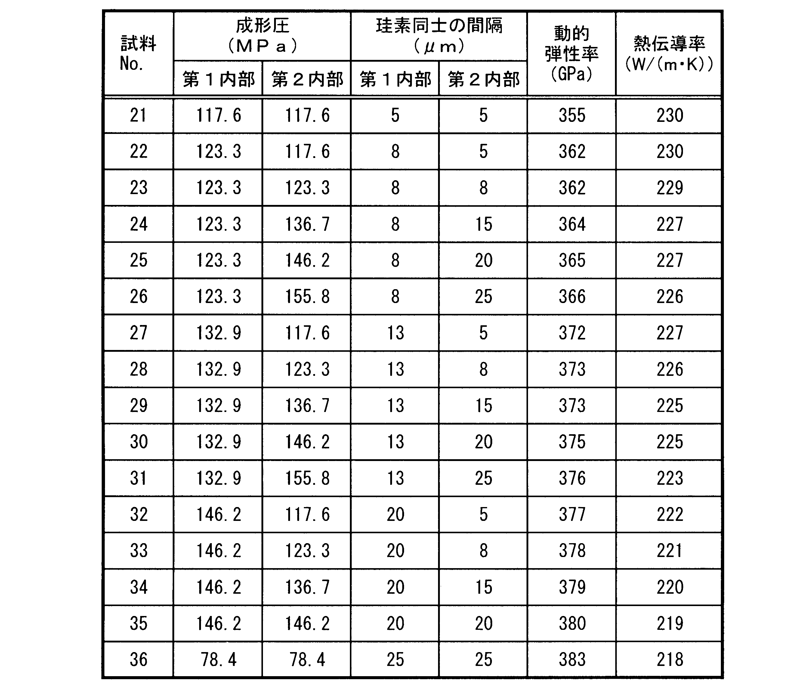
まず、本実施形態の接合体からなる試料を準備した。各試料に含まれる炭化珪素の含有量は81質量%、珪素の含有量は19質量%になるように調整した。ここで、第1内部および第2内部を得るために、成形する際に用いる圧力を成形圧として表3に示した。各試料の第1当接面および第2当接面を含む断面を研磨して得られる鏡面を実施例1で示した方法と同じ方法で空隙の有無を観察した結果、いずれの試料も空隙がないことを確認した。 (Example 3)
First, a sample made of the joined body of the present embodiment was prepared. The content of silicon carbide contained in each sample was adjusted to 81% by mass, and the content of silicon was adjusted to 19% by mass. Here, Table 3 shows the pressure used in molding to obtain the first interior and the second interior as molding pressure. The mirror surface obtained by polishing the cross section including the first contact surface and the second contact surface of each sample was observed for the presence or absence of voids in the same manner as in Example 1. As a result, all samples had voids. Confirmed not.
1 第1複合体
11 第1外層部
12 第1内部
13 第1凹部
14 第1内層部
15 第1当接面
2 第2複合体
21 第2外層部
22 第2内部
23 第2凹部
24 第2内層部
25 第2当接面 REFERENCE SIGNS
Claims (8)
- 外面側に位置し酸化珪素を主成分として含む第1外層部、および該第1外層部に囲繞される炭化珪素および珪素を含む第1内部を有する第1複合体を得る工程と、
外面側に位置し酸化珪素を主成分として含む第2外層部、および該第2外層部に囲繞される炭化珪素および珪素を含む第2内部を有する第2複合体を得る工程と、
前記第1内部が前記第2内部に当接する第1当接面、および前記第2内部が前記第1内部に当接する第2当接面の少なくとも一方を、研削または研磨する工程と、
前記第1当接面と前記第2当接面とを当接させ、真空雰囲気中または不活性ガス雰囲気中で熱処理する工程と、
を含む、接合体の製造方法。 obtaining a first composite having a first outer layer located on the outer surface side and containing silicon oxide as a main component, and a first interior containing silicon carbide and silicon surrounded by the first outer layer;
obtaining a second composite having a second outer layer portion located on the outer surface side and containing silicon oxide as a main component, and a second inner portion containing silicon carbide and silicon surrounded by the second outer layer portion;
grinding or polishing at least one of a first contact surface on which the first interior contacts the second interior and a second contact surface on which the second interior contacts the first interior;
a step of contacting the first contact surface and the second contact surface and performing heat treatment in a vacuum atmosphere or an inert gas atmosphere;
A method of manufacturing a conjugate, comprising: - 前記第1当接面が、深さ方向に向かって第1凹部または第1貫通孔を備える、請求項1に記載の接合体の製造方法。 The manufacturing method of the joined body according to claim 1, wherein the first contact surface has a first concave portion or a first through hole extending in the depth direction.
- 前記第1複合体が、前記第1凹部の内壁面および内底面の少なくとも一方、または前記第1貫通孔の内壁面に、酸化珪素を主成分として含む第1内層部を備える、請求項2に記載の接合体の製造方法。 3. The method according to claim 2, wherein the first composite includes a first inner layer portion containing silicon oxide as a main component on at least one of the inner wall surface and the inner bottom surface of the first recess, or on the inner wall surface of the first through hole. A method of manufacturing the described conjugate.
- 前記第2当接面が、深さ方向に向かって第2凹部または第2貫通孔を備える、請求項1~3のいずれかに記載の接合体の製造方法。 The method for manufacturing a joined body according to any one of claims 1 to 3, wherein the second contact surface has a second concave portion or a second through hole extending in the depth direction.
- 前記第2複合体が、前記第2凹部の内壁面および内底面の少なくとも一方、または前記第2貫通孔の内壁面に、酸化珪素を主成分として含む第2内層部を備える、請求項4に記載の接合体の製造方法。 5. The method according to claim 4, wherein the second composite includes a second inner layer portion containing silicon oxide as a main component on at least one of the inner wall surface and the inner bottom surface of the second recess or the inner wall surface of the second through hole. A method of manufacturing the described conjugate.
- 前記第1内部および前記第2内部の少なくとも一方における炭化珪素の含有量が、70質量%以上92質量%以下である、請求項1~5のいずれかに記載の接合体の製造方法。 The method for manufacturing a joined body according to any one of claims 1 to 5, wherein the content of silicon carbide in at least one of said first interior and said second interior is 70% by mass or more and 92% by mass or less.
- 前記第1内部および前記第2内部の少なくとも一方において、珪素の重心間距離の平均値と珪素の円相当径の平均値との差が、8μm以上20μm以下である、請求項1~6のいずれかに記載の接合体の製造方法。 7. The difference between the average distance between the centers of gravity of silicon and the average equivalent circle diameter of silicon is 8 μm or more and 20 μm or less in at least one of the first interior and the second interior. 2. A method for producing a conjugate according to claim 1.
- 前記第1内部および前記第2内部の少なくとも一方の閉気孔率が、0.1%以下である、請求項1~7のいずれかに記載の接合体の製造方法。 The method for manufacturing a joined body according to any one of claims 1 to 7, wherein at least one of the first interior and the second interior has a closed porosity of 0.1% or less.
Priority Applications (2)
| Application Number | Priority Date | Filing Date | Title |
|---|---|---|---|
| EP22780681.7A EP4317111A1 (en) | 2021-03-29 | 2022-03-28 | Method for producing assembly |
| JP2023511223A JPWO2022210470A1 (en) | 2021-03-29 | 2022-03-28 |
Applications Claiming Priority (2)
| Application Number | Priority Date | Filing Date | Title |
|---|---|---|---|
| JP2021-056172 | 2021-03-29 | ||
| JP2021056172 | 2021-03-29 |
Publications (1)
| Publication Number | Publication Date |
|---|---|
| WO2022210470A1 true WO2022210470A1 (en) | 2022-10-06 |
Family
ID=83459057
Family Applications (1)
| Application Number | Title | Priority Date | Filing Date |
|---|---|---|---|
| PCT/JP2022/014812 WO2022210470A1 (en) | 2021-03-29 | 2022-03-28 | Method for producing assembly |
Country Status (3)
| Country | Link |
|---|---|
| EP (1) | EP4317111A1 (en) |
| JP (1) | JPWO2022210470A1 (en) |
| WO (1) | WO2022210470A1 (en) |
Citations (5)
| Publication number | Priority date | Publication date | Assignee | Title |
|---|---|---|---|---|
| JPH0274572A (en) * | 1988-09-09 | 1990-03-14 | Ngk Insulators Ltd | Bonding of sintered silicon carbide |
| JPH02107580A (en) * | 1988-09-27 | 1990-04-19 | Norton Co | Method for bonding silicon carbide part and composite silicon carbide structure |
| JP2007153700A (en) * | 2005-12-07 | 2007-06-21 | Toshiba Ceramics Co Ltd | Method of joining silicon carbide porous ceramic and joined member |
| JP2009078943A (en) * | 2007-09-26 | 2009-04-16 | Covalent Materials Corp | Method for joining silicon carbide ceramic material |
| JP2019055897A (en) * | 2017-09-21 | 2019-04-11 | 日本特殊陶業株式会社 | Production method of silicon carbide member |
-
2022
- 2022-03-28 WO PCT/JP2022/014812 patent/WO2022210470A1/en active Application Filing
- 2022-03-28 EP EP22780681.7A patent/EP4317111A1/en active Pending
- 2022-03-28 JP JP2023511223A patent/JPWO2022210470A1/ja active Pending
Patent Citations (6)
| Publication number | Priority date | Publication date | Assignee | Title |
|---|---|---|---|---|
| JPH0274572A (en) * | 1988-09-09 | 1990-03-14 | Ngk Insulators Ltd | Bonding of sintered silicon carbide |
| JPH02107580A (en) * | 1988-09-27 | 1990-04-19 | Norton Co | Method for bonding silicon carbide part and composite silicon carbide structure |
| JP2007153700A (en) * | 2005-12-07 | 2007-06-21 | Toshiba Ceramics Co Ltd | Method of joining silicon carbide porous ceramic and joined member |
| JP2009078943A (en) * | 2007-09-26 | 2009-04-16 | Covalent Materials Corp | Method for joining silicon carbide ceramic material |
| JP4954838B2 (en) | 2007-09-26 | 2012-06-20 | コバレントマテリアル株式会社 | Joining method of silicon carbide ceramic material |
| JP2019055897A (en) * | 2017-09-21 | 2019-04-11 | 日本特殊陶業株式会社 | Production method of silicon carbide member |
Also Published As
| Publication number | Publication date |
|---|---|
| JPWO2022210470A1 (en) | 2022-10-06 |
| EP4317111A1 (en) | 2024-02-07 |
Similar Documents
| Publication | Publication Date | Title |
|---|---|---|
| US9255747B2 (en) | Cooling plate, method for manufacturing the same, and member for semiconductor manufacturing apparatus | |
| RU2505378C2 (en) | Aluminium-diamond composite material and its production method | |
| JP5759152B2 (en) | Aluminum-diamond composite and method for producing the same | |
| EP0833698B1 (en) | Method of coating, method for making ceramic-metal structures, method for bonding, and structures formed thereby | |
| WO2007074720A1 (en) | Semiconductor element mounting substrate, semiconductor device using the same, and process for producing semiconductor element mounting substrate | |
| US20040240142A1 (en) | Bonding member and electrostatic chuck | |
| JP6708460B2 (en) | Method for manufacturing joined body | |
| Johnson et al. | Effect of liquid content on distortion and rearrangement densification of liquid-phase-sintered W-Cu | |
| US20170120339A1 (en) | New powder metal process for production of components for high temperature useage | |
| JP2008132562A (en) | Vacuum chuck and vacuum suction device using it | |
| KR20170031688A (en) | Method for producing a component | |
| JP4868885B2 (en) | Method for producing silicon-silicon carbide composite member | |
| JP5729517B1 (en) | Reaction sintered silicon carbide member | |
| WO2022210470A1 (en) | Method for producing assembly | |
| JP2010173873A (en) | Ceramic joined body and supporting member using the same | |
| JP5231064B2 (en) | Vacuum adsorption apparatus and method for manufacturing the same | |
| JP4624690B2 (en) | Cutting tool insert and method of manufacturing the same | |
| WO2019194137A1 (en) | SiC-Si COMPOSITE MEMBER PRODUCTION METHOD AND SiC-Si COMPOSITE MEMBER | |
| JP5046859B2 (en) | Bonded body, adsorbing member, adsorbing apparatus and processing apparatus | |
| CN111377741B (en) | Articles including silicon carbide and methods of making the same | |
| CN113084176A (en) | Self-supporting diamond film/Cu composite heat sink material and preparation method thereof | |
| JP2018070413A (en) | Slide component and faucet valve | |
| JP2005118979A (en) | Grinding/polishing vacuum chuck and sucking plate | |
| KR101871104B1 (en) | Joining material for ceramics and method of ceramics joined body | |
| JP4731368B2 (en) | Vacuum chuck and vacuum suction device using the same |
Legal Events
| Date | Code | Title | Description |
|---|---|---|---|
| 121 | Ep: the epo has been informed by wipo that ep was designated in this application |
Ref document number: 22780681 Country of ref document: EP Kind code of ref document: A1 |
|
| WWE | Wipo information: entry into national phase |
Ref document number: 2023511223 Country of ref document: JP |
|
| WWE | Wipo information: entry into national phase |
Ref document number: 18553323 Country of ref document: US |
|
| WWE | Wipo information: entry into national phase |
Ref document number: 2022780681 Country of ref document: EP |
|
| NENP | Non-entry into the national phase |
Ref country code: DE |
|
| ENP | Entry into the national phase |
Ref document number: 2022780681 Country of ref document: EP Effective date: 20231030 |