WO2022210412A1 - 表示部を有するロボットを備えるロボットシステム - Google Patents
表示部を有するロボットを備えるロボットシステム Download PDFInfo
- Publication number
- WO2022210412A1 WO2022210412A1 PCT/JP2022/014620 JP2022014620W WO2022210412A1 WO 2022210412 A1 WO2022210412 A1 WO 2022210412A1 JP 2022014620 W JP2022014620 W JP 2022014620W WO 2022210412 A1 WO2022210412 A1 WO 2022210412A1
- Authority
- WO
- WIPO (PCT)
- Prior art keywords
- display
- robot
- unit
- image
- coordinate system
- Prior art date
- Legal status (The legal status is an assumption and is not a legal conclusion. Google has not performed a legal analysis and makes no representation as to the accuracy of the status listed.)
- Ceased
Links
Images












Classifications
-
- B—PERFORMING OPERATIONS; TRANSPORTING
- B25—HAND TOOLS; PORTABLE POWER-DRIVEN TOOLS; MANIPULATORS
- B25J—MANIPULATORS; CHAMBERS PROVIDED WITH MANIPULATION DEVICES
- B25J9/00—Program-controlled manipulators
- B25J9/02—Program-controlled manipulators characterised by movement of the arms, e.g. cartesian coordinate type
- B25J9/023—Cartesian coordinate type
-
- B—PERFORMING OPERATIONS; TRANSPORTING
- B25—HAND TOOLS; PORTABLE POWER-DRIVEN TOOLS; MANIPULATORS
- B25J—MANIPULATORS; CHAMBERS PROVIDED WITH MANIPULATION DEVICES
- B25J9/00—Program-controlled manipulators
- B25J9/16—Program controls
- B25J9/1679—Program controls characterised by the tasks executed
- B25J9/1689—Teleoperation
-
- B—PERFORMING OPERATIONS; TRANSPORTING
- B25—HAND TOOLS; PORTABLE POWER-DRIVEN TOOLS; MANIPULATORS
- B25J—MANIPULATORS; CHAMBERS PROVIDED WITH MANIPULATION DEVICES
- B25J17/00—Joints
-
- B—PERFORMING OPERATIONS; TRANSPORTING
- B25—HAND TOOLS; PORTABLE POWER-DRIVEN TOOLS; MANIPULATORS
- B25J—MANIPULATORS; CHAMBERS PROVIDED WITH MANIPULATION DEVICES
- B25J9/00—Program-controlled manipulators
- B25J9/16—Program controls
- B25J9/1628—Program controls characterised by the control loop
- B25J9/1635—Program controls characterised by the control loop flexible-arm control
-
- B—PERFORMING OPERATIONS; TRANSPORTING
- B25—HAND TOOLS; PORTABLE POWER-DRIVEN TOOLS; MANIPULATORS
- B25J—MANIPULATORS; CHAMBERS PROVIDED WITH MANIPULATION DEVICES
- B25J9/00—Program-controlled manipulators
- B25J9/16—Program controls
- B25J9/1656—Program controls characterised by programming, planning systems for manipulators
-
- G—PHYSICS
- G05—CONTROLLING; REGULATING
- G05B—CONTROL OR REGULATING SYSTEMS IN GENERAL; FUNCTIONAL ELEMENTS OF SUCH SYSTEMS; MONITORING OR TESTING ARRANGEMENTS FOR SUCH SYSTEMS OR ELEMENTS
- G05B2219/00—Program-control systems
- G05B2219/30—Nc systems
- G05B2219/40—Robotics, robotics mapping to robotics vision
- G05B2219/40169—Display of actual situation at the remote site
-
- G—PHYSICS
- G05—CONTROLLING; REGULATING
- G05B—CONTROL OR REGULATING SYSTEMS IN GENERAL; FUNCTIONAL ELEMENTS OF SUCH SYSTEMS; MONITORING OR TESTING ARRANGEMENTS FOR SUCH SYSTEMS OR ELEMENTS
- G05B2219/00—Program-control systems
- G05B2219/30—Nc systems
- G05B2219/40—Robotics, robotics mapping to robotics vision
- G05B2219/40478—Graphic display of work area of robot, forbidden, permitted zone
Definitions
- the present invention relates to a robot system equipped with a robot having a display unit.
- a robot system comprises a robot and a working tool attached to the robot.
- the robot can perform a given task while changing its position and posture.
- a robot is composed of a plurality of components such as an arm.
- a robot system in which a display device is attached to a constituent member of the main body of the robot.
- Japanese Patent Publication No. 2018-529488 proposes a holding device for medical use in which a display unit composed of a ring of an LED (Light Emitting Diode) member, etc., is arranged on the joint axis, and the display unit indicates the movement direction, etc. It is
- the robot changes its position and posture in order to move the work tool.
- the display unit is arranged on the constituent member of the robot
- the position and posture of the display unit change together with the constituent member.
- the orientation of the image displayed on the display unit changes for the operator, and the image displayed on the display unit may be difficult to see.
- a robot system includes a robot including a plurality of joint axes, and a display section arranged on a body portion of the robot.
- the robot system includes a display control unit that controls an image displayed in the display area of the display unit, and a reference direction setting unit that sets a reference direction that is a reference direction when determining the orientation of the image displayed on the display unit.
- the display control unit controls the orientation of the image in the display area of the display unit, based on the position of each joint axis of the robot and the reference direction, so as to display a predetermined posture relationship with respect to the reference direction. to display.
- a robot system that includes a display unit that is attached to the main body of the robot, and in which an image displayed on the display unit is easy to see when the position and posture of the robot change.
- FIG. 1 is a schematic diagram of a robot system in an embodiment; FIG. It is a schematic diagram explaining the joint axis of the robot in the embodiment.
- 1 is a block diagram of a robot system in an embodiment; FIG. It is the schematic of the robot explaining the planar display part attached to a robot. It is the schematic of the robot explaining the curved-surface-shaped display part attached to a robot. It is the 1st image displayed on a display part. It is a 2nd image displayed on a display part. It is a 3rd image displayed on a display part.
- 4 is a flow chart of control for displaying an image on the display section in the embodiment. 4 is a plan view for explaining a display coordinate system, reference points, reference planes, and display phase directions; FIG. FIG.
- FIG. 4 is a schematic diagram illustrating first control for setting a reference direction
- FIG. 9 is a schematic diagram illustrating second control for setting a reference direction
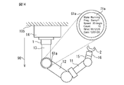
- FIG. 11 is a first schematic diagram of the robot for explaining third control for setting a reference direction
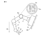
- FIG. 11 is a second schematic diagram of the robot for explaining third control for setting the reference direction
- FIG. 11 is a third schematic diagram of the robot for explaining third control for setting a reference direction
- FIG. 11 is a schematic diagram illustrating fourth control for setting a reference direction
- FIG. 11 is a schematic diagram illustrating fifth control for setting a reference direction
- FIG. 4 is a schematic diagram illustrating first control for setting a display phase direction
- FIG. 11 is a schematic diagram illustrating second control for setting the display phase direction
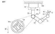
- FIG. 11 is a schematic diagram of a robot for explaining third control for setting the display phase direction;
- FIG. 11 is a schematic diagram illustrating third control for setting the display phase direction;
- FIG. 11 is a schematic diagram illustrating fourth control for setting the display phase direction;
- FIG. 4 is a schematic diagram showing the display phase direction of the display unit when the robot is in the first position and posture;
- FIG. 10 is a schematic diagram showing the display phase direction when the robot is driven from the first position and posture and the display is controlled;
- FIG. 10 is a schematic diagram showing the display phase direction when the robot is driven from the first position and orientation and display control is not performed;
- Fig. 4 is a schematic diagram of the robot in a second position and pose;
- FIG. 11 is a schematic plan view showing the display phase direction of the display unit when the robot is in the second position and posture;
- FIG. 10 is a schematic plan view showing the display phase direction when the robot is driven from the second position and posture and the display is controlled;
- FIG. 10 is a schematic plan view showing the display phase direction when the robot is driven from the second position and orientation and display control is not performed;
- Fig. 3 is a schematic diagram of the robot in a third position and posture;
- FIG. 10 is a schematic front view showing the display phase direction of the display unit when the robot is driven from the third position and posture and the display is controlled;
- 10 is a schematic front view showing the display phase direction of the display unit when the robot is driven from the third position and orientation and display control is not performed; It is a 4th image displayed on a display part. It is the 5th image displayed on a display part. It is the 6th image displayed on a display part. It is the 7th image displayed on a display part. It is the 8th image displayed on a display part. It is a ninth image displayed on the display unit. 10 is a tenth image displayed on the display unit. 11 is an eleventh image displayed on the display unit;
- FIG. A robot system includes a robot including a plurality of joint axes and a display device for displaying predetermined information.
- the display unit of the display device is arranged on the main body of the robot.
- FIG. 1 shows a schematic diagram of a first robot system in this embodiment.
- the robot system 6 of this embodiment has a function of transporting a work.
- the robot system 6 includes a robot device including a hand 2 as a work tool (end effector) and a robot 1 that changes the position and orientation of the hand 2 .
- a robot system 6 includes a control device 4 that controls the robot 1 and the hand 2 .
- the robot 1 of this embodiment includes a base portion 14 fixed to an installation surface and a swivel base 13 supported by the base portion 14 .
- the swivel base 13 is formed to rotate with respect to the base portion 14 .
- Robot 1 includes upper arm 11 and lower arm 12 .
- the lower arm 12 is rotatably supported by a swivel base 13 via a joint.
- the upper arm 11 is rotatably supported by the lower arm 12 via joints.
- the upper arm 11 rotates around a rotation axis parallel to the direction in which the upper arm 11 extends.
- Robot 1 includes a wrist 15 connected to the end of upper arm 11 .
- the wrist 15 is rotatably supported by the upper arm 11 via joints.
- the wrist 15 includes a flange 16 that rotates around an axis of rotation along the direction in which the wrist 15 extends.
- Hand 2 is fixed to flange 16 .
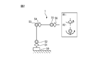
- FIG. 2 shows a schematic diagram of the robot for explaining the joint axes of the robot of this embodiment.
- a joint axis is an axis of a joint portion that connects links that constitute a robot, and is a portion that changes the positional relationship or angular relationship between the links.
- the positional relationship between the links can be changed by changing the axis position of each axis (the position is the angle in the case of a rotating axis, and the length of displacement in the case of a linear axis).
- An actuator for moving the joint axis may be installed at a location different from the joint axis.
- the robot 1 of the present embodiment is configured with six joint axes. These six joint axes are, in order from the side of the pedestal 59 that is the base portion 14 of the robot 1, the first joint axis J1 axis 51, the second joint axis J2 axis 52, the third joint axis J3 axis 53, the third joint axis
- the fourth joint axis is the J4 axis 54
- the fifth joint axis is the J5 axis 55
- the sixth joint axis is the J6 axis 56.
- the J1 axis 51, the J4 axis 54, and the J6 axis 56 are configured as a rotation axis R1 that rotates around the link that connects the joint axes.
- the J2 axis 52, the J3 axis 53, and the J5 axis 55 are configured as a rotation axis R2 that rotates in a direction perpendicular to the link that connects the axes.
- the hand 2 of this embodiment grips and releases the workpiece.
- the hand 2 grips the work by closing the claws facing each other.
- a work tool is not limited to a hand that grips a work. Any work tool can be attached to the robot according to the work to be performed by the robot system. For example, if the robot system performs arc welding, a welding torch can be attached to the robot.
- FIG. 2 is a simple explanatory diagram showing the configuration of the axes of the robot 1.
- FIG. Also, if the origin of the joint axis is the origin of the coordinate system (joint coordinate system) set for each axis and the point where the links are connected, then the position of the origin of the axis is on the coordinate system set in space. is represented as the position of
- a reference coordinate system 87 of the robot is used as a reference when representing the position and orientation of the robot, such as the joint axes, links, tip, and work tools attached to the tip of the robot, which are set in space. called.
- the reference coordinate system 87 is a coordinate system in which the position of the origin and the direction of the coordinate axes are fixed in the space in which the robot is arranged.
- the position of the joint axis is the angle of the rotation axis.
- Moving the position of the joint shaft means rotating the rotation shaft to change the position.
- the position of the joint shaft is the position in the moving direction of the linear motion shaft.
- To move the position of the joint axis means to change the position by moving the linear motion axis.
- the coordinate system set with respect to the space is an orthogonal coordinate system fixed with respect to the space.
- the coordinate system set with respect to the robot device is defined as the tool coordinate system.
- Control points are the origin of the tool coordinate system, a translational point, and a center point for rotational movement.
- the six axes of the robot 1 are all rotary axes, but the robot 1 may also include linear axes.
- the robot 1 of this embodiment is a vertically articulated robot configured with six axes. However, as long as the position of each axis can be controlled and the orthogonal position can be controlled, any robot having other forms may be used.
- the position and orientation of the robot or parts of the robot are determined taking into account the drive of those drive devices.
- the reference coordinate system of the robot may be set with respect to the space.
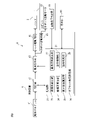
- FIG. 3 shows a block diagram of the robot system in this embodiment.
- robot 1 includes a robot driving section that changes the position and posture of robot 1 .
- the robot drive section includes a robot drive motor 19 as an actuator for driving components such as arms.
- the robot driving unit drives actuators arranged on the joint shafts so as to move the rotational positions of the robot 1 on the respective joint shafts.
- the robot drive unit may be configured with any principle or power as long as it can drive the joint shaft of the robot to displace it.
- the robot driving section drives an actuator arranged on the joint shaft so as to move the position on the linear motion shaft.
- the hand 2 has a hand driving section that drives the hand 2 .
- the hand driving section includes a pressurizing pump, valves, and the like for driving the claws of the hand 2 .
- the control device 4 includes an arithmetic processing device (computer) having a CPU (Central Processing Unit) as a processor.
- the arithmetic processing unit has a RAM (Random Access Memory), a ROM (Read Only Memory), etc., which are connected to the CPU via a bus.
- the motion program 41 contains commands for driving the robot 1 and the hand 2 .
- the robot system 6 is driven based on the operation program 41 to transport the work.
- the control device 4 includes a storage unit 42 that stores information.
- the storage unit 42 stores information regarding control of the robot 1 and the hand 2 .
- the operating program 41 is stored in the storage unit 42 .
- the storage unit 42 can be configured with a non-temporary storage medium.
- the storage unit 42 can be configured with a storage medium capable of storing information such as a volatile memory, a nonvolatile memory, a magnetic storage medium, or an optical storage medium.
- the control device 4 includes an operation command section 43 that sends an operation command.
- the operation command unit 43 corresponds to a processor driven according to the operation program 41 .
- the processor functions as an operation command unit 43 by reading the operation program 41 and executing control defined in the operation program 41 .
- the robot drive section is driven based on the motion command for the robot 1 output from the motion command section 43 , and the rotational position of the robot drive motor 19 on the joint shaft of the robot 1 is changed.
- the motion command unit 43 sends a motion command for driving the robot 1 to the robot drive circuit 45 .
- Robot drive circuit 45 includes electrical circuitry that drives robot drive motor 19 .
- the robot drive circuit 45 supplies electricity to the robot drive motor 19 based on the operation command.
- the operation command unit 43 sends an operation command for driving the hand 2 to the hand drive circuit 44 .
- Hand drive circuitry 44 includes electrical circuitry that drives the hand drive.
- the hand driving circuit 44 supplies electricity to the hand driving section based on the operation command.
- the control device 4 of the present embodiment is installed away from the robot 1, it is not limited to this form.
- the controller may be located inside the robot.
- the robot 1 is equipped with a rotational position detector 18 that outputs axis position data that is the rotational position of the joint axis of the robot 1 .
- the rotational position detector 18 is composed of, for example, an encoder. The position and orientation of the robot 1 can be detected from the output of the rotational position detector 18 .
- the rotational position detector 18 of this embodiment is attached to a robot drive motor 19 arranged corresponding to each joint axis.
- the robot system 6 of this embodiment includes a display device that displays arbitrary information.
- the display device includes at least one display unit 60 arranged on the body portion of the robot 1 .
- a display section 61a is attached to a joint section between the swivel base 13 and the lower arm 12.
- the display device includes a processing section 21 that generates images to be displayed on the display section 60 and processes commands from the display section 60 .
- the processing unit 21 is configured by the control device 4 .
- the processing unit 21 includes a reference direction setting unit 22 that sets a reference direction, which is a reference direction when determining the orientation of the image displayed on the display unit 60 .
- Processing unit 21 includes coordinate system setting unit 23 that sets a display coordinate system, which is a coordinate system set for the display area of display unit 60 .
- the processing unit 21 includes a coordinate system calculation unit 24 that calculates the position and orientation of the display coordinate system based on the axis position of each joint axis of the robot 1 .
- the processing unit 21 includes a display phase calculation unit 25 that calculates a display phase direction, which is a reference direction for the display orientation on the display area of the display unit 60 .
- the processing unit 21 includes an offset angle setting unit 26 that sets the offset angle of the image displayed by the display unit.
- Processing unit 21 includes a command processing unit 29 that processes commands input by operating display unit 60 .
- Processing unit 21 includes a display control unit 27 that controls an image displayed in the display area of display unit 60 .
- the processing unit 21 corresponds to a processor driven according to the operating program 41 .
- the processor functions as the processing unit 21 by reading the operating program 41 and performing control defined in the operating program 41 .
- reference direction setting unit 22, coordinate system setting unit 23, coordinate system calculation unit 24, display phase calculation unit 25, offset angle setting unit 26, display control unit 27, and command processing unit 29 included in processing unit 21 each , corresponds to a processor driven according to the operating program 41 .
- the processors function as respective units by executing control defined in the operating program 41 .
- the robot system 6 of the present embodiment includes one or more display units 60 on the main body portions of the robot, such as links such as robot arms, joint axes, and arm tips.
- the display unit 60 is attached to a component of the robot that changes its position and posture by being driven by the robot driving unit.
- the display unit 60 changes its position and posture by being driven by the robot on the joint shaft.
- the robot may be mounted on a drive that changes its position and attitude.
- the present invention is applicable even when the position and posture of the display unit 60 are changed by the driving device.
- the display unit 60 of the display device can adopt any display panel that can display characters or pictures so that they can be recognized.
- a liquid crystal display panel or an organic EL (Electro Luminescence) display panel can be adopted.
- the display unit 60 is configured so as to be appropriately attached to the portion where it is installed, and is preferably thin.
- the display unit 60 preferably has a shape that does not protrude greatly from the main body of the robot.
- the display unit 60 is integrated with the main body of the robot and has a shape with a smooth outer surface.
- FIG. 4 shows a schematic diagram of a robot for explaining examples of various display units according to the present embodiment.
- the display portions 61a, 61b, 61c, 62, 63a, 63b, 64, and 65 are formed in a plate shape so as to have a planar display area.
- the display portions 61a and 61b are fixed to the joint portions so that the display areas are perpendicular to the J2 axis 52 and the J3 axis 53, respectively.
- the display portion 61c is fixed to the joint portion so that the display area is perpendicular to the J5 axis 55. As shown in FIG.
- the display parts 61a, 61b, 61c move together with the joint parts.
- the display unit 62 is fixed to the swivel base 13 so that the display area is parallel to the J1 axis.
- the display unit 62 rotates together with the swivel base 13 .
- the display units 63a and 63b are fixed to the upper arm 11 so that the display areas are parallel to the J4 axis 54. As shown in FIG.
- the display units 63 a and 63 b move together with the upper arm 11 .
- the display unit 64 is arranged so that the display area is parallel to the J5 axis 55 .
- the display unit 65 is fixed to the wrist 15 so that the display area is parallel to the J6 axis 56 . Display units 64 and 65 move with list 15 .
- each display unit 61a, 61b, 61c, 62, 63a, 63b, 64, 65 are fixed to the components of the robot 1 and move together with the components of the robot 1.
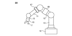
- FIG. 5 shows a schematic diagram of another robot for explaining examples of various display units of the present embodiment.
- the display units 66 and 67 are configured by flexible display panels.
- the display portions 66 and 67 are formed so that the display areas extend in the circumferential direction along the surfaces of the constituent members of the robot 1 .
- the display units 66 and 67 can be composed of a thin and flexible display panel such as an organic EL display panel.
- the display part 66 is fixed so as to be wound around the lower arm 12 .
- the display portion 66 is formed so that the display area is parallel to the extending direction of the lower arm 12 .
- the display unit 67 is fixed so as to be wound around the upper arm 11 .
- the display portion 67 is formed so that the display area is parallel to the direction in which the upper arm 11 extends.
- the display units 66 and 67 are fixed to components of the robot 1 and move together with the components of the robot 1 .
- the display units 66 and 67 of the present embodiment are composed of one display panel, but are not limited to this form.
- a plurality of display panels may be arranged around the constituent members of the robot 1, and the display section may be configured so as to surround the constituent members.
- One image may be displayed on a plurality of display panels.
- FIG. 6 shows the first image displayed on the display unit.
- FIG. 7 shows the second image displayed on the display unit.
- the display unit 61a disposed between the swivel base 13 and the lower arm 12 will be described as an example.
- the display control section 27 of the display device can display an image in the display area of the display section 61a based on data transmitted from another device.
- the information displayed on the display unit includes, for example, the operating state of the robot, the name of the operating program being executed, the operating program execution status, the alarm status, the robot driving speed, the number of times the work has been performed, and the This includes the number of times the
- the driving speed or operating speed of the robot may be the translational speed or rotational speed of the tip of the robot or the tool coordinate system.
- the driving speed or operating speed of the robot may be the rotational speed of each joint axis. The same applies to the following description unless otherwise specified.
- the information displayed on the display unit includes the cause of a problem, the countermeasure method, the details of the next task to be executed, the connection status of the network to which the robot is connected, and the robot drive unit that drives the robot. It includes the load status of the included actuators, the current time, the date and time, and the elapsed time of the work.
- the information to be displayed on the display unit may be information related to the work or settings of the robot, or arbitrary information sent to the robot from an external device, etc., which is displayed on the main body of the robot to provide information to the operator. Useful information is preferred.
- the second image 71b also displays information on driving the robot.
- FIG. 8 shows the third image displayed on the display unit.
- the display unit may have not only a display function of displaying information, but also an input function of inputting predetermined information by operator's operation.
- the display device can display an input image for inputting predetermined information on the display unit.
- the third image 72a is an input image for setting the joint axis on which the display unit is arranged or the driving speed around the desired joint axis. It should be noted that there are cases in which joint shafts other than one joint shaft are driven together with one joint shaft. In this case, when changing the driving speed around one joint axis, the driving speeds of all joint axes may be adjusted so that the position and posture of the tip of the robot do not change. Further, in the input image displayed on the display unit, the movement speed of the robot tip in the operating program being executed may be changed.
- the display device may function as an input device into which information is input by the operator's operation according to the input image. Furthermore, the display device can function as a teaching device for manually driving the robot or creating an operation program.
- the display device can include, as a display unit, a touch panel type display panel that allows input operations.
- the display may include buttons or the like to perform an emergency stop or desired function.
- the display device in the present embodiment includes both a device having only a display function and a device having both a display function and an input function.
- a command input to display portion 60 of the display device is sent to command processing portion 29 .
- the command processing unit 29 processes the input commands.
- the command processing unit 29 sends a robot motion command to the motion command unit 43 and changes the set values for driving the robot stored in the storage unit 42 .
- the display control unit 27 can display any input image in the display area. For example, it is possible to display an image of a software keyboard, an image of numbers only, or an image in which a bar-shaped image such as a slide bar is moved to change the numerical value to be input. In addition, the display control unit 27 can display an image for continuous input operation by rotating a predetermined image, an image to be rotated like a dial of an analog telephone, buttons related to screen changes, or the like. .
- any input method can be used, such as input by touching the display area like a touch panel, or non-contact input by a capacitive sensor. can be adopted.
- non-contact input information can be input by operating in the space above the display area.
- a device for detecting an input operation a device using any sensing method such as a capacitive sensor, an optical sensor, an optical camera, an infrared camera, or an ultrasonic sensor can be used.
- a contact or non-contact sensor may be operated as a contact sensor for detecting contact with a person or surrounding objects, in addition to being an input device for inputting information. That is, by switching the operation mode, a sensor that detects an input operation may be used as a sensor for ensuring safety.
- Information input to the display device is transmitted to another device such as a robot control device or a device connected via a network through wired or wireless communication.
- the input information may be stored and memorized in a teaching device including a display function.
- Information calculated or processed based on the input information may be displayed on the display unit of the display device.
- the input image which is an image for the operator to input information, is preferably configured so that arbitrary information can be input for setting or confirmation.
- the input image is preferably configured so that a change in setting value, a change in the driving speed of the robot, an instruction to make the robot stand by, a change in robot operation, a robot drive, or an operation interruption can be input.
- the input image can be used to input information such as tools or workpieces for exchanging the tool attached to the tip of the robot, set the coordinate system, position teaching, change to direct teach mode, or automatic operation mode.
- It may be an image for any input, such as changes to It is preferable to limit the functions that can operate setting values to functions that are frequently used or simple functions.
- the input image may be formed so that the type of input function can be changed.
- the display unit may display an image for accepting input of specific information to enable input operations by the operator.
- the display unit may be switched to an image that can be operated by the operator by inputting specific information by the operator. For example, a button that enables input may be pressed for a predetermined period of time or longer, a password may be entered, or a touching finger may be moved to pass a predetermined point on the display area.
- the display control unit may display an image that prohibits input operations in order to prevent erroneous input operations or the like. Then, an image that enables an input operation may be displayed by an operation such as inputting a password by the operator.
- the display device When inputting information on the display device, it may be possible to change at least one of the authority for the input operation and the authority for the information to be displayed by a predetermined input operation. For example, by performing a predetermined input operation, it is possible to change the items that can be set, change the behavior of the robot, change the range of values that can be set, or change the information that is displayed. can do.
- the display device may change the instructions or information that can be input, or the data or information that can be displayed.
- the display part may be detachable from the main body of the robot.
- the display device having the display unit and the display device constituting the teaching device may be formed so as to be detachable from the main body of the robot.
- the display device can be equipped with a battery.
- the display device is preferably powered when attached to the main body of the robot.
- a device that transmits information to be displayed on the display device or a device that transmits information input to the display device can be formed to be connected by wire or wirelessly.
- the display coordinate system set for the display unit is configured so that a coordinate system generated in advance according to the mounting position is applied by mounting the display unit at a predetermined position on the main body of the robot. can do.
- the display coordinate system may be directly input after mounting the display unit, or may be set by a conventional method.
- the display device that is detachable from the robot functions as a teaching device, it can be used only when the teaching device is required.
- the teaching device can be installed and used only in a necessary part of the robot. For this reason, while improving the operability of the robot, it is possible to reduce the cost of the robot system and reduce the risk of the teaching device being damaged due to a collision with a peripheral device during operation of the robot.
- FIG. 9 shows a flowchart of control for displaying an image on the display section according to the present embodiment.
- coordinate system setting unit 23 sets a display coordinate system corresponding to the display unit, a reference plane and a reference point set in the display coordinate system. set.
- the coordinate system setting unit 23 sets a display coordinate system, a reference plane, and a reference point, for example, according to an operator's operation.
- the reference direction setting unit 22 sets a reference direction, which is a direction that serves as a reference for display, through predetermined control.
- the storage unit 42 stores the display coordinate system, reference plane, reference point, and reference direction.
- the processing unit 21 acquires the display coordinate system, the reference plane, and the reference point from the storage unit 42.
- the processing unit 21 acquires the reference direction from the storage unit 42 .
- the coordinate system calculation unit 24 calculates the position and orientation of the display coordinate system based on the position and orientation of the robot 1 . Specifically, the coordinate system calculator 24 calculates the position and orientation of the display coordinate system based on the output of the rotational position detector 18 . The position and orientation of the reference plane expressed in the display coordinate system and the position of the reference point are calculated.
- the display phase calculation unit 25 calculates the display phase direction on the reference plane based on the reference direction and the reference point. That is, the display phase calculation unit 25 sets the orientation of the image on the display unit.
- the display control unit 27 generates an image on the reference plane based on the display phase direction.
- the display control section 27 displays an image on the display section 60 based on the image on the reference plane.
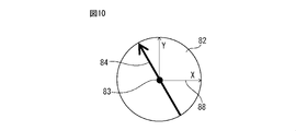
- FIG. 10 shows a schematic plan view for explaining the display coordinate system, reference plane, reference point, and display phase direction.
- FIG. 10 corresponds to a plan view of the display area of the display section 61a.
- the coordinate system setting unit 23 of the processing unit 21 sets a display coordinate system 88, which is a coordinate system set for the display area of the display unit.
- the coordinate system setting unit 23 is a reference plane of the display area of the display unit, and includes a reference plane 82 set on the display coordinate system and a point serving as a display reference on the display area of the display unit.
- a reference point 83 set on the system is set with respect to the display area of the display unit.
- the display coordinate system can be set at any position and orientation with respect to the display area of the display unit.
- the display coordinate system represents the position and orientation of the display unit or display area installed on the main body of the robot on a reference coordinate system such as the robot's reference coordinate system.
- the display coordinate system is set so that the plane formed by the two coordinate axes and the display area are on the same plane.
- a reference plane is a plane used as a reference when representing an image to be output to the display area of the display unit on a plane.
- the reference plane is a plane set on the display coordinate system. The position and orientation of the reference plane in the display coordinate system can be determined in advance.
- the reference plane is set to a plane including two coordinate axes of the display coordinate system.
- the reference point is a point that determines the center position of the image to be output to the display area of the display unit. The image is oriented by rotating the image about the reference point in the reference plane.
- the reference direction can be set in any direction independently from the display coordinate system.
- a reference point is set on the reference plane.
- the reference plane can be set independently of the directions of the coordinate axes of the display coordinate system.
- the reference plane may be tilted with respect to the XY plane of the display coordinate system.
- the display area of the display unit is planar, it is preferable that the display area, the reference plane, and the plane formed by the two coordinate axes of the display coordinate system be coplanar. By setting in this way, the amount of calculation can be reduced.
- a reference point can be set on the display area and a plane tangent to the reference point can be used as the reference plane. In this case, even if the XY plane and the reference plane in the display coordinate system are coplanar, the reference plane does not include the display area.
- the display control unit 27 can generate an image to be displayed on the reference plane.
- the display control section 27 can generate an image to be displayed on the display section by projecting the image on the reference plane onto the display area of the display section.
- the coordinate system setting unit 23 can set the display coordinate system 88, the reference plane 82, and the reference point 83 by arbitrary control.
- the operator can predetermine the display coordinate system 88 , the reference plane 82 and the reference point 83 based on the shape of the display area of the display unit and input them to the processing unit 21 .
- these set values are set for the display unit, and can be set in advance as standard set values before the display unit is attached to the robot.
- the operator can change the set values as needed. For example, after setting a standard value for the display unit, the operator may change the standard value for display according to the state of the robot to be displayed on the display unit so as to be convenient for the work.
- the coordinate system setting unit 23 may automatically set the display coordinate system 88, the reference plane 82, and the reference point 83 for the display unit.
- the display may have a large display area.
- flexible displays may be wrapped around the robot components.
- the coordinate system setting unit 23 automatically sets the display coordinate system, the reference plane, and the reference point so that the image is displayed in the same direction regardless of the rotational positions of the constituent members. I don't mind.
- the coordinate system setting unit 23 may automatically set the displayed setting values by moving them around the joint axis.
- a plurality of display units may be combined and arranged so as to surround the constituent members of the robot.
- a display coordinate system, a reference plane, and a reference point may be set for each display area of one display unit.
- a display coordinate system, a reference plane, and a reference point may be set by combining a plurality of display units into one display unit in a predetermined portion of the robot. In this case, control may be performed so that images are distributed and displayed on the respective display units.
- the display control unit 27 defines a reference point 83 that is a reference point for display on the display area of the display unit, and a direction that is calculated by the display phase calculation unit 25 and serves as a reference for the orientation of display on the display area of the display unit. Based on the display phase direction (the direction indicated by the arrow 84), the position and direction (phase) of the display in the display area of the display unit are controlled and displayed. For example, the display control unit 27 can display the image so that the direction indicated by the arrow 84 is the upper side of the image.
- the display control unit 27 determines the center position of the display on the display area of the display unit by using the reference point 83 .
- the display control unit 27 determines the orientation of the display by rotating the image on the reference plane 82 with the reference point 83 as the center of rotation.
- the origin of the display coordinate system 88 and the reference point are arranged at the same position in the present embodiment, they may be arranged at different positions.
- a display phase direction indicated by an arrow 84 exists on the reference plane 82 and is set to pass through the reference point 83 .
- the reference plane 82 is preferably parallel to or on the same plane as the display area.
- the display area of the display section has a planar shape, but it may have a curved shape instead of a planar shape.
- the tangential plane at a predetermined point on the display area can be used as the reference plane.
- the reference plane can be a plane formed by two coordinate axes of the display coordinate system.
- the image displayed in the display area of the display unit can be displayed based on the reference point and the display phase direction, or can be displayed by projecting the image on the reference plane onto the display area.
- the image displayed in the display area may be displayed by any method, such as being displayed based on calculated information.
- the display area of the display unit 61a (the part where the image of the display panel is displayed) is circular, but may be any shape such as a regular polygon.
- the reference point can be placed in the center of the display area.
- the reference point can be set at the position of the center of gravity of the shape of the display area.
- the coordinate system calculator 24 calculates the position and orientation of the display coordinate system 88 based on the positions of the joint axes of the robot 1 .
- the coordinate system calculation unit 24 calculates the axis positions (angles in the case of rotation axes) of each joint axis of the robot 1, the relationship between the positions and orientations of the joint axes represented by DH (Denavit Hartenberg) parameters, etc., and the joint axes.
- DH Densvit Hartenberg
- the relationship between the joint coordinate system and the position and orientation of the display unit (the position and orientation of the display coordinate system 88) is defined.
- the joint axes sequentially connected via the links are positioned and oriented with respect to the joint coordinate system set for the closest joint axis from the display unit toward the base 59 side of the robot. It is preferable to set the relationship in advance.
- a simultaneous transformation matrix (relationship between position and orientation) in a reference coordinate system up to a joint axis for which the relationship between position and orientation with respect to the display unit is fixed is determined.
- the position and orientation of the display coordinate system on the reference coordinate system can be obtained from the homogeneous transformation matrix of the joint axis and the display unit.
- the robot is mounted on a device that changes the position and orientation of the robot, such as a travel axis or another drive device, calculate the position and orientation of the display coordinate system by considering the amount of movement of those drive parts. You may do so.
- the position and orientation of the display coordinate system are the relationship of the relative position and orientation with respect to a driven peripheral device installed separately from the robot.
- the relative position and orientation of the display coordinate system shall be determined in consideration of changes in the position and orientation of all driving parts up to the display coordinate system, including the driving device installed separately from the robot. You may make it calculate.
- the reference direction setting unit 22 sets a reference direction, which is a direction used as a reference when determining the orientation of the image displayed on the display unit.
- the reference direction setting unit 22 sets the direction on the reference coordinate system 87 of the robot 1 as the reference direction.
- the reference direction may be a direction on a coordinate system that is convenient for setting the reference direction.
- the reference direction setting unit 22 may set the reference direction using a coordinate system that is set so as to be fixed with respect to the space in which the robot system exists.
- the reference direction setting unit 22 uses a reference coordinate system 87 that is set for the robot 1 and represents the position and posture of the robot such as each joint or arm tip of the robot 1 to determine the direction on the reference coordinate system 87 of the robot.
- the reference direction may be set according to the direction of .
- the reference direction setting unit 22 may set the reference direction using a coordinate system set for a predetermined portion of the robot 1 . It should be noted that in this case the reference direction changes along with the driving or movement of the predetermined part of the robot.
- the reference direction setting unit 22 sets the reference direction using the reference coordinate system of devices around the robot, such as devices, jigs, another robot, or another driving device arranged near the robot 1. You may make it At this time, the reference direction setting unit 22 may set the reference direction to a portion of the surrounding device whose position and orientation changes due to the driving or movement of the surrounding device. Note that in this case, the reference direction changes with the drive or movement of the surrounding devices.
- the reference direction setting unit By setting the reference direction in the desired coordinate system by the reference direction setting unit, it is possible to set the direction in which the operator can easily see the image displayed by the display unit. Also, in the input image for performing the input operation, it is possible to set the direction in which the input is facilitated. In addition, various other methods for setting the reference direction are conceivable, and an example will be shown below.
- FIG. 11 shows a perspective view of the reference plane for explaining the first control in which the reference direction setting unit sets the reference direction.
- the reference direction setting unit 22 sets the reference direction so as to form a predetermined posture relationship with respect to the normal direction at the reference point 83 of the reference plane 82 set for the display area in the reference coordinate system 87 of the robot. May be set.
- the reference direction setting unit 22 may set a direction obtained by a predetermined homogeneous transformation matrix with respect to the normal direction as the reference direction.
- the reference plane 82 and the display area of the display are coplanar. For this reason, the reference direction setting unit 22 may set the reference direction so as to form a predetermined attitude relationship with respect to the normal direction of the display area on the reference coordinate system 87 of the robot.
- the reference direction setting unit 22 calculates the normal direction of the reference plane 82 so as to pass through the reference point 83 as indicated by the arrow 82a.
- the reference direction setting unit 22 inclines the normal direction at the direction and angle of the arrow 91 expressed in the reference coordinate system 87 .
- a direction indicated by an arrow 81 is a direction parallel to the reference direction.
- the reference direction setting unit 22 sets a direction parallel to the direction indicated by the arrow 81 as the reference direction indicated by the arrow 80 .
- the reference direction can be stably set.
- a predetermined direction in the reference coordinate system of the robot such as the direction of gravity
- the display phase direction cannot be determined when the normal direction of the display area of the display unit is parallel to the reference direction.
- this problem does not occur and the reference direction can be stably set.
- the attitude relationship between the display unit and the reference direction may change during the period when control is being performed to set a predetermined direction in the reference coordinate system of the robot as the reference direction.
- the reference plane on the display area of the display unit and the reference direction are orthogonal to each other, or have an attitude relationship that is nearly orthogonal.
- large changes occur frequently.
- the calculation of the display phase direction may become unstable.
- the control may be switched to set the reference direction from the normal direction of the reference plane.
- the image is displayed on the display area of the display unit in a direction that maintains a predetermined posture relationship in the reference coordinate system of the robot. can be made easier to see.
- FIG. 12 shows a schematic plan view for explaining the second control in which the reference direction setting unit sets the reference direction.
- the reference direction setting unit 22 may set the reference direction according to the range of positions where the display unit exists and the range of the posture of the display unit on a reference coordinate system such as the reference coordinate system 87 of the robot.
- the position where the display unit exists the position where the origin or reference point of the display coordinate system exists can be adopted.
- the orientation of the display unit the orientation of the display coordinate system can be adopted.
- the reference direction may be changed according to the position of the display unit on the reference coordinate system.
- the range for setting the reference direction according to the position where the display unit exists may be the range defined by the two coordinate axes of the robot's reference coordinate system. Also, the range for determining the position where the display unit exists may be a range defined by one or three coordinate axes of the reference coordinate system of the robot.
- the reference direction setting unit 22 can set the reference direction indicated by the arrow 80a when the display unit is arranged within the range 101a.
- the reference direction setting unit 22 can set the reference direction indicated by the arrow 80b when the display unit is arranged within the range 101b.
- the reference direction setting unit 22 can set reference directions indicated by arrows 80c and 80d when the display units are arranged within the ranges 101c and 101d. Reference directions in the respective ranges 101a, 101b, 101c, and 101d can be set in the reference coordinate system 87.
- the operator can easily see the image displayed by the display unit according to the position range or posture range of the display unit. can be done.
- the operator can easily input in the input image. For example, when a plurality of workers are working around the robot, each worker can easily see the display by changing the reference direction according to the working range of the workers.
- FIG. 13 shows a first schematic diagram of the robot for explaining the third control in which the reference direction setting unit sets the reference direction.
- FIG. 14 shows a second schematic diagram of the robot for explaining the third control in which the reference direction setting unit sets the reference direction.
- FIG. 15 shows a third schematic diagram of the robot for explaining the third control in which the reference direction setting section sets the reference direction. 13 to 15 show enlarged views of an image 71a displayed on the display section 61a in addition to schematic views of the robot.
- the robot 1 is arranged above the installation surface 105 .
- the robot 1 is arranged below the installation surface 105 .
- the robot 1 is suspended.
- the installation surface 105 is inclined.
- the base portion 14 is fixed to the installation surface 105 .
- An arrow 90 indicates the direction of gravity (downward in the vertical direction).
- the reference direction setting unit 22 may set the reference direction in the direction of gravity, the direction opposite to the direction of gravity, or the direction obtained by rotating the direction of gravity in a predetermined posture. That is, the reference direction setting unit 22 may set the direction determined by the reference coordinate system 87 as the reference direction. In the examples shown in FIGS. 13 to 15, the reference direction is set vertically upward (opposite to the direction indicated by arrow 90). Each display part 61a is arranged in various directions. However, regardless of the orientation of the display section 61a, the display control section 27 displays the image 71a such that the upward direction in the vertical direction is the upper side of the image.
- the third control is effective when the normal direction of the display area (reference plane) of the display unit forms a certain angle or more with the direction of gravity. Since the reference direction determined by this control is based on the direction of gravity, it is a direction that is intuitively understandable to the operator.
- the display device may be controlled to display an image while maintaining a predetermined angle of 0 degrees or more with respect to the horizontal direction regardless of the angle of the joint axis of the robot provided with the display unit.
- the input image such as the displayed button may be controlled to be displayed while maintaining a predetermined angle with respect to the horizontal direction. good.
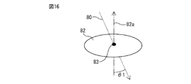
- FIG. 16 shows a perspective view of the reference plane for explaining the fourth control in which the reference direction setting unit sets the reference direction.
- the angle formed by the reference direction and the normal direction of the reference plane may change due to the driving of the robot, and the angle formed by the reference direction and the normal direction of the reference plane may become smaller than a predetermined threshold.
- the angle ⁇ 1 formed between the reference direction indicated by the arrow 80 and the normal direction of the reference plane 82 indicated by the arrow 82a may become smaller than a predetermined threshold.
- the reference direction setting unit 22 may not change the reference direction before the angle ⁇ 1 becomes smaller than the predetermined threshold. That is, the reference direction setting unit 22 may maintain the previous reference direction when the position and posture of the robot change and the angle ⁇ 1 becomes smaller than a predetermined threshold value.
- the orientation relationship between the display area of the display unit and the reference direction changes due to driving of the robot, and the reference direction becomes closer to the normal direction of the reference plane 82, the orientation of the image on the display unit (display phase direction) may not be able to be calculated stably. In such a situation, by continuing without changing the reference direction, it is possible to determine the orientation of the image and display the image.
- FIG. 17 shows a perspective view of the reference plane for explaining the fifth control in which the reference direction setting unit sets the reference direction.
- the reference direction setting section 22 may set the reference direction based on the position specified by the operator on the display area of the display section.
- the reference plane 82 is set on the same plane as the display area of the display unit.
- the operator changes the position and posture of the robot 1 so that the reference plane 82 has a desired posture.
- the display control section 27 displays the reference point 83 in the display area of the display section.
- the display unit is composed of a touch panel type display panel
- the operator designates the designated point 102 by pressing a desired point in the display area of the display unit.
- the reference direction setting unit 22 calculates the direction from the reference point 83 indicated by the arrow 81 toward the designated point 102 .
- the reference direction setting unit 22 sets the direction parallel to the arrow 81 as the reference direction indicated by the arrow 80 .
- the reference direction can be set in the reference coordinate system of the robot.
- the reference direction is set in the plane of the display area of the display unit.
- the desired reference direction is a direction that intersects the plane of the display area of the display unit. the operator changes the position and posture of the robot to change the orientation of the display area of the display unit. be able to.
- the reference direction can be easily set so that the image is oriented in a direction convenient for the worker according to the state of the robot.
- This control makes it possible to easily set a reference direction in which the operator can easily see the display on the display unit. In addition, the operator can easily input in the input image.
- the display area and the reference plane may not be on the same plane.
- the display area of the display unit may be formed in a curved surface.
- the reference direction setting unit can project the designated point designated by the operator onto the reference plane in a predetermined direction. Then, the reference direction may be set based on the points projected onto the reference plane.
- the direction from the reference point to the specified point is set as the reference direction, but it is not limited to this form.
- An arbitrary direction based on a specified point specified in the display area by the operator can be set as the reference direction.
- control may be performed to designate a designated point on the display area.
- FIG. 18 shows a perspective view of the reference plane for explaining the first control for calculating the display phase direction.
- the display phase calculation unit 25 projects a reference direction indicated by an arrow 80 onto a reference plane 82 that is a reference plane of the display area of the display unit, thereby calculating the orientation of the display on the display area of the display unit.
- the display phase direction (the direction indicated by the arrow 84), which is the direction in which the FIG. 18 shows a case where the reference direction indicated by arrow 80 and the normal direction of reference plane 82 indicated by arrow 82a are orthogonal.
- the display phase calculator 25 can project the reference direction in an arbitrary direction as indicated by an arrow 92 .
- the display phase calculator 25 projects the reference direction toward the reference plane 82 .
- a display phase direction indicated by an arrow 84 can be determined so as to pass through the reference point 83 .
- FIG. 19 shows a perspective view of the reference plane for explaining the second control for calculating the display phase direction.
- FIG. 19 shows a case where the reference direction indicated by arrow 80 is not orthogonal to the normal direction of reference plane 82 indicated by arrow 82a but is inclined.
- display phase calculator 25 calculates a direction parallel to the reference direction passing through reference point 83 as indicated by arrow 81 .
- the display phase calculator 25 projects a direction parallel to the reference direction passing through the reference point 83 onto the normal direction of the display area as indicated by an arrow 92 .
- the display phase calculator 25 projects a direction parallel to the reference direction passing through the reference point 83 onto the reference plane 82 .
- this control as indicated by an arrow 84, it is possible to determine the display phase direction, which is the reference of the display phase on the display coordinate system.
- the display phase calculation unit 25 calculates a direction in which the reference direction indicated by the arrow 80 is projected onto the reference plane 82 toward the normal direction of the display area. Then, the display phase calculator 25 calculates a direction passing through the reference point 83 so as to be parallel to the projected direction. The display phase calculator 25 can determine this direction as the display phase direction.
- FIG. 20 shows a schematic diagram of the robot for explaining the third control for calculating the display phase direction.
- FIG. 21 shows a plan view of the reference plane for explaining the third control for calculating the display phase direction.
- display phase calculator 25 projects the reference direction onto reference plane 82, which is the reference plane of the display area of display unit 61a. Furthermore, the display phase calculation unit 25 calculates the display phase direction by rotating at an offset angle that is a predetermined angle around a reference point 83 that is a reference point for display on the display area of the display unit. You may make it
- the reference direction is set vertically upward as indicated by an arrow 80 .
- the display phase calculator 25 calculates a direction parallel to the reference direction on the reference plane 82 by projecting the reference direction onto the reference plane 82 .
- the display phase calculator 25 calculates a direction parallel to the reference direction passing through the reference point 83 as indicated by an arrow 81 .
- the processing unit 21 of the present embodiment includes an offset angle setting unit 26 that sets an offset angle, which is a predetermined angle centered on a reference point on the display area.
- the offset angle setting section 26 sets the offset angle according to the operator's operation. For example, the operator uses the teaching console to input the offset angle ⁇ 2. Then, the offset angle setting unit 26 can set the offset angle ⁇ 2 with respect to the direction indicated by the arrow 81 which is the projection of the reference direction onto the reference plane.
- the display phase calculator 25 rotates around the reference point 83 in the direction indicated by the arrow 81 at the offset angle ⁇ 2, which is a predetermined rotation angle.
- the display phase calculator 25 rotates the projected direction of the reference direction within the reference plane 82 .
- the display phase calculator 25 then calculates the display phase direction indicated by the arrow 84 .
- the display control unit 27 controls and displays the orientation of the image on the display area of the display unit 61a.
- the image 71a displayed on the display unit 61a is inclined at an offset angle ⁇ 2 with respect to the projection of the reference direction onto the reference plane.
- An image can be displayed so as to have a predetermined phase relationship with respect to a predetermined direction based on the reference direction.
- the information is displayed according to the specific direction, making it easier to see the information.
- the display device has an input function, the operator can easily perform an input operation on the input image.
- FIG. 22 shows a plan view of the reference plane for explaining the fourth control for setting the display phase direction.
- the reference plane 82 and the display area of the display section are arranged on the same plane.
- the offset angle setting section 26 is formed so that the offset angle ⁇ 2 can be set by the operator's operation of the display area of the display section.
- the display control unit 27 displays the direction obtained by projecting the current reference direction onto the reference plane 82 as indicated by an arrow 81 .
- the operator presses the display area of the display unit to designate the designated point 103 .
- the offset angle setting unit 26 calculates the offset angle ⁇ 2 with respect to the direction indicated by the arrow 81 .
- the display phase calculator 25 sets the display phase direction based on the offset angle ⁇ 2. Based on the display phase direction calculated by the display phase calculation unit 25 and the reference point 83, the display control unit 27 controls and displays the orientation of the image on the display area of the display unit 61a.
- the offset angle may be set based on a point obtained by projecting the contact point of the operator on the display area onto the reference plane.
- the offset angle may be calculated based on a point obtained by projecting a specified point specified by the operator in the normal direction of the reference plane.
- control for rotating the image based on such an offset angle may not be performed.
- the display control section 27 controls the image displayed in the display area of the display section. Further, when the display unit displays the input image, the display control unit 27 controls the orientation of the input image and displays it.
- the display control unit 27 controls the image on the display area of the display unit so as to display an image having a predetermined attitude relationship with respect to the reference direction based on the axis position of each axis of the joint axes of the robot and the reference direction. to control the orientation of the display.
- the display control unit 27 also controls the axis position of each joint axis of the robot, the reference direction, the reference point on the display coordinate system, and the display phase direction on the display coordinate system calculated by the display phase calculation unit 25. Based on and, the position and orientation of the image on the display area of the display unit are controlled and displayed.
- the robot may be installed in a device that has a travel axis or a device that changes the position and posture of the robot, such as another drive device.
- the processing unit 21 preferably displays an image based on the position of each joint axis of the robot and the amount of movement of these drive parts.
- the display control unit 27 controls the orientation of the image on the display area of the display unit, so that the image on the display area of the display unit is displayed in a desired orientation when the posture of the display unit changes due to the driving of the robot. can do.
- an input operation can be performed by displaying an input image in a desired direction.
- FIG. 23 shows a schematic side view of the robot when the robot is in the first position and posture.
- a reference direction indicated by the arrow 80 is vertically upward.
- Such a reference direction can be set by, for example, the first control or the third control for setting the reference direction of this embodiment.
- the display phase direction indicated by the arrow 84 faces the same direction as the reference direction indicated by the arrow 80.
- FIG. 24 shows a schematic diagram of the robot when the robot is driven from the first position and posture.
- FIG. 25 shows a schematic diagram of the robot of the comparative example when the robot is driven from the first position and posture.
- the axial position of the J2 shaft 52 between the swivel base 13 and the lower arm 12 has changed.
- the lower arm 12 rotates to change its posture.
- FIG. 24 shows the state of the image of the display unit 61a when the display is controlled by the processing unit 21 of the present embodiment.
- the display control unit 27 controls the display area of the display unit 61a to display an image having a predetermined posture relationship with respect to the reference direction based on the axis position of each joint axis of the robot 1 and the reference direction. controls the orientation of the image in
- the display phase direction indicated by arrow 84 remains parallel to the reference direction. That is, the display phase direction is maintained upward in the vertical direction.
- the display control of the present embodiment is not implemented.
- the display phase direction indicated by the arrow 85 rotates together with the rotation of the lower arm 12.
- the image displayed on the display section 61a is tilted. It becomes difficult for the operator to see the image displayed on the display unit 61a.
- FIG. 26 shows a schematic side view of the robot when the robot is in the second position and posture.
- FIG. 27 shows a schematic plan view of the robot when the robot is in the second position and posture.
- the display area (reference plane) of the display section 63b is parallel to the horizontal direction.
- the reference direction indicated by the arrow 80 is set in the horizontal direction.
- Such a reference direction can be set by the first control, second control, or third control for setting the reference direction of the present embodiment.
- the display phase direction indicated by the arrow 84 is horizontal. Also, the operator looks at the display section 63b from above the robot 1 as indicated by an arrow 94 .
- the display phase direction indicated by the arrow 84 is the direction in which the operator can easily see the image.
- Fig. 28 shows a schematic diagram of the robot when it is driven from the second position and orientation.
- FIG. 29 shows a schematic diagram of the robot of the comparative example when the robot is driven from the second position and orientation.
- the swing base 13 rotates around the J1 axis 51 as indicated by an arrow 95 .
- display control is performed by the processing unit 21 .
- the display control unit 27 controls the image on the display area of the display unit based on the axis positions of the joint axes of the robot and the reference direction so as to display a predetermined attitude relationship with respect to the reference direction.
- the direction is controlled and displayed.
- the display phase direction indicated by arrow 84 is parallel to the reference direction indicated by arrow 80 .
- the display control of the present embodiment is not implemented.
- the direction of the display phase indicated by the arrow 85 in the display portion 63b changes as the upper arm 11 rotates.
- the image displayed on the display section 63b is tilted. It becomes difficult for the operator to see the image displayed on the display unit 63b.
- the display phase direction indicated by arrow 84 is the direction parallel to the reference direction even if the axis position of the joint axis changes. is maintained.
- the image displayed on the display unit 63b is displayed in the same orientation even when the robot is driven. Therefore, it is possible for the operator to maintain an easy-to-see state of the image displayed on the display unit 63b.
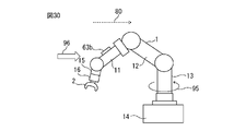
- Fig. 30 shows a schematic side view of the robot when the robot is in the third position and posture.
- the upper arm 11 to which the display portion 63b is fixed is tilted with respect to the horizontal direction.
- the reference direction indicated by the arrow 80 is set to face the horizontal direction.
- Such a reference direction can be set by the second control or third control for setting the reference direction of this embodiment.
- the normal direction of the display area (reference plane) of the display section 63b is not orthogonal to the reference direction. Then, the operator looks at the display section 63b in the direction indicated by the arrow 96.
- FIG. 31 shows an explanatory diagram of the display phase direction when the robot is driven from the third position and orientation.
- pivot base 13 pivots about J1 axis 51 as indicated by arrow 95.
- display control is performed by the processing unit 21 .
- the display control unit 27 controls the image on the display area of the display unit so as to display an image having a predetermined attitude relationship with respect to the reference direction based on the axis position of each axis of the joint axes of the robot and the reference direction. to control the orientation of the display.
- the display phase direction indicated by arrow 84 is maintained in the direction in which the reference direction is projected onto the display area (reference plane) of display section 63b.
- the display phase direction indicated by the arrow 84 is the direction in which the operator can easily see the image.
- FIG. 32 shows an explanatory diagram of the display phase direction of a comparative example when the robot is driven from the third position and orientation.
- the display control of the present embodiment is not performed.
- the display phase direction indicated by the arrow 85 in the display portion 63b changes its direction along with the rotation of the upper arm 11 indicated by the arrows 95a and 95b.
- the image displayed on the display section 63b is tilted. It becomes difficult for the operator to see the image displayed on the display unit 63b.
- the display phase direction maintains the direction in which the operator can easily see the image even if the joint axis position changes. ing. Therefore, it is possible for the operator to maintain an easy-to-see state of the image displayed on the display unit 63b.
- the display coordinate system, reference plane, and reference point are set for the display area of the display unit to calculate the display phase direction, but the present invention is not limited to this form.
- the processing unit does not have to set the display coordinate system, the reference plane, and the reference point.
- the processing unit can calculate the display phase direction by arbitrary control based on the reference direction. For example, when the reference direction is parallel to the display area of the display unit, the processing unit may set the reference direction to the display phase direction.
- the display control unit may perform image processing on the image generated on the reference plane. For example, any image transformation operation can be performed, such as image enlargement, image reduction, or a predetermined image transformation. Then, the display control section can display the converted image on the display section. For example, as described above, when the display area of the display unit has a curved surface, an image to be displayed on the display area can be generated by projecting an image on the reference plane onto the display area of the display unit. .
- FIG. 33 shows the fourth image displayed on the display unit.
- FIG. 34 shows the fifth image displayed on the display unit.
- a fourth image 71c is an image showing the driving state of the robot.
- the fifth image 72b is an input image for inputting the driving speed around the joint axis on which the display unit is arranged or a desired joint axis. It should be noted that there are cases in which joint shafts other than one joint shaft are driven together with one joint shaft. In this case, when changing the driving speed around one joint axis, the driving speeds of all joint axes may be adjusted so that the position and posture of the tip of the robot do not change. Further, in the input image displayed on the display unit, the movement speed of the robot tip in the operating program being executed may be changed.
- the display control unit 27 can display information or an input image in at least one of characters, graphics, symbols, colors, and patterns in the display area of the display unit.
- the display control unit 27 may display the orientation of the image by at least one of characters, graphics, symbols, colors, and patterns.
- an arrow image 73 indicating the upper side of the image is displayed.
- the display control unit generates an image in the display area so that the orientation of the image can be recognized, thereby making it easier for the operator to recognize the orientation of the image in the display area of the display unit. Further, when the display unit displays the input image, it is possible to improve the operability of the operator.
- FIG. 35 shows the sixth image displayed on the display unit.
- FIG. 36 shows the seventh image displayed on the display section.
- characters "upper" indicating the upper side of the image are displayed.
- the seventh image 71e the upper side of the image is shown by partially recessing the frame surrounding the information indicating the driving state.
- FIG. 37 shows the eighth image displayed on the display unit.
- FIG. 38 shows the ninth image displayed on the display unit.
- a pattern indicating the upper side is displayed at the top.
- the pattern indicating the upper side is displayed in a color different from the background color of the display area. In this manner, the display control unit 27 can generate an image so as to indicate the orientation of the image in various forms.
- the display control unit should display the image so that the orientation of the image can be understood.
- the display control unit may display characters or the like indicating the lower side of the image.
- FIG. 39 shows the tenth image displayed on the display unit.
- FIG. 40 shows the eleventh image displayed on the display unit.
- the display control unit 27 may perform control to change the size of the image of a predetermined portion on the display area of the display unit 61a according to the movement speed of the display unit 61a of the display device accompanying the driving of the robot. For example, the display control unit 27 may display a predetermined image in a small size when the moving speed of the display unit 61a is slow, and may display a predetermined image in a large size when the moving speed of the display unit 61a is high. .
- the display control unit 27 can change the size of the image of the number of times of execution, as indicated by an arrow 97, according to the moving speed of the display unit 61a. For example, the display control unit 27 can calculate the moving speed of the display coordinate system as the moving speed of the display unit 61a. The display control unit 27 acquires the position and time of the origin of the display coordinate system at predetermined time intervals. The display control unit 27 can calculate the moving speed of the origin of the display coordinate system based on the position of the origin of the display coordinate system and the time.
- the display control unit 27 can display the image of the number of times of implementation in a small size as shown in the image 71ha.
- the display control unit 27 can display the image of the number of times of implementation in a large size as shown in the image 71hb.
- the eleventh images 72ca and 72cb in FIG. 40 are input images for the operator to perform an input operation.
- a predetermined set value can be changed by pressing a "+" button or a "-" button.
- the display control unit 27 can change the size of the image showing the set values as indicated by an arrow 98 according to the moving speed of the display unit 61a. Also, the display control unit 27 can change the size of the button.
- the display control unit 27 can display the image of the setting value large and the image of the button small as shown in the image 72ca.
- the display control unit 27 can display the image of the set value small and the image of the button large as shown in the image 72ca. With this control, the image of the button is enlarged even if the driving speed of the robot is increased, so that the operator can stably press the button.
- the worker can perform input operations while the robot is driving.
- the operator can easily see the image and perform the input operation.
- the operator can easily perform an input operation by displaying a large image of the button when the moving speed of the display unit increases.
- the set values that can be input may be changed depending on the moving speed of the robot or the driving speed of the joint shaft.
Landscapes
- Engineering & Computer Science (AREA)
- Robotics (AREA)
- Mechanical Engineering (AREA)
- Manipulator (AREA)
Priority Applications (4)
| Application Number | Priority Date | Filing Date | Title |
|---|---|---|---|
| DE112022000760.5T DE112022000760T5 (de) | 2021-03-31 | 2022-03-25 | Robotersystem mit roboter und anzeigeeinheit |
| US18/546,972 US12569980B2 (en) | 2021-03-31 | 2022-03-25 | Robot system comprising robot equipped with display unit |
| JP2023511196A JP7704839B2 (ja) | 2021-03-31 | 2022-03-25 | 表示部を有するロボットを備えるロボットシステム |
| CN202280023620.XA CN117042933B (zh) | 2021-03-31 | 2022-03-25 | 具备具有显示部的机器人的机器人系统 |
Applications Claiming Priority (2)
| Application Number | Priority Date | Filing Date | Title |
|---|---|---|---|
| JP2021060530 | 2021-03-31 | ||
| JP2021-060530 | 2021-03-31 |
Publications (1)
| Publication Number | Publication Date |
|---|---|
| WO2022210412A1 true WO2022210412A1 (ja) | 2022-10-06 |
Family
ID=83456194
Family Applications (1)
| Application Number | Title | Priority Date | Filing Date |
|---|---|---|---|
| PCT/JP2022/014620 Ceased WO2022210412A1 (ja) | 2021-03-31 | 2022-03-25 | 表示部を有するロボットを備えるロボットシステム |
Country Status (6)
| Country | Link |
|---|---|
| US (1) | US12569980B2 (https=) |
| JP (1) | JP7704839B2 (https=) |
| CN (1) | CN117042933B (https=) |
| DE (1) | DE112022000760T5 (https=) |
| TW (1) | TW202239555A (https=) |
| WO (1) | WO2022210412A1 (https=) |
Families Citing this family (1)
| Publication number | Priority date | Publication date | Assignee | Title |
|---|---|---|---|---|
| DE102023123838A1 (de) * | 2023-09-05 | 2025-03-06 | B. Braun New Ventures GmbH | Medizinisches Robotersystem mit angezeigter Aktivierungstaste sowie Aktivierungsverfahren |
Citations (5)
| Publication number | Priority date | Publication date | Assignee | Title |
|---|---|---|---|---|
| WO2013114737A1 (ja) * | 2012-01-31 | 2013-08-08 | 株式会社五合 | 機器の表示装置および表示装置を設けた機器 |
| JP2015182142A (ja) * | 2014-03-20 | 2015-10-22 | セイコーエプソン株式会社 | ロボット、ロボットシステム及び教示方法 |
| JP2017030058A (ja) * | 2015-07-29 | 2017-02-09 | セイコーエプソン株式会社 | ロボット、ロボット制御装置およびロボットシステム |
| JP2018045526A (ja) * | 2016-09-15 | 2018-03-22 | 京セラドキュメントソリューションズ株式会社 | パスワード入力装置、および画像処理装置 |
| JP6846412B2 (ja) * | 2017-03-21 | 2021-03-24 | Idec株式会社 | イネーブルスイッチおよび操作部 |
Family Cites Families (17)
| Publication number | Priority date | Publication date | Assignee | Title |
|---|---|---|---|---|
| JPH0481081A (ja) | 1990-07-20 | 1992-03-13 | Fujitsu General Ltd | Cctvシステムのカメラ装置 |
| CA2438005A1 (en) * | 2001-02-07 | 2002-08-15 | Synthes (U.S.A.) | Device and method for intraoperative navigation |
| JP4262014B2 (ja) * | 2003-07-31 | 2009-05-13 | キヤノン株式会社 | 画像撮影装置および画像処理方法 |
| JP4519883B2 (ja) | 2007-06-01 | 2010-08-04 | 株式会社コナミデジタルエンタテインメント | キャラクター表示装置、キャラクター表示方法、ならびに、プログラム |
| US8659658B2 (en) * | 2010-02-09 | 2014-02-25 | Microsoft Corporation | Physical interaction zone for gesture-based user interfaces |
| DE102012103032B3 (de) * | 2012-04-05 | 2013-07-04 | Reis Group Holding Gmbh & Co. Kg | Verfahren zur Bedienung eines Industrieroboters |
| EP3269323B1 (de) | 2015-08-12 | 2019-03-20 | medineering GmbH | Medizinischer haltearm mit ringförmigen led-anzeigemitteln |
| US9855664B2 (en) | 2015-11-25 | 2018-01-02 | Denso Wave Incorporated | Robot safety system |
| JP6420229B2 (ja) * | 2015-12-10 | 2018-11-07 | ファナック株式会社 | 仮想物体の画像をロボットの映像に重畳表示する映像表示装置を備えるロボットシステム |
| JP6457441B2 (ja) | 2016-07-12 | 2019-01-23 | ファナック株式会社 | ロボットの重心表示装置、ロボット制御装置およびロボットシミュレーション装置 |
| WO2018076109A1 (en) * | 2016-10-24 | 2018-05-03 | Torus Biomedical Solutions Inc. | Systems and methods for producing real-time calibrated stereo long radiographic views of a patient on a surgical table |
| JP6857052B2 (ja) * | 2017-03-03 | 2021-04-14 | 株式会社キーエンス | ロボット設定装置、ロボット設定方法、ロボット設定プログラム及びコンピュータで読み取り可能な記録媒体並びに記録した機器 |
| JP2018200527A (ja) | 2017-05-26 | 2018-12-20 | 富士通株式会社 | 情報処理装置、方法、及びプログラム |
| CN107662195A (zh) * | 2017-09-22 | 2018-02-06 | 中国东方电气集团有限公司 | 一种具有临场感的机器手主从异构遥操作控制系统及控制方法 |
| JP6683671B2 (ja) | 2017-11-24 | 2020-04-22 | ファナック株式会社 | ジョグ座標系を設定するロボットの制御装置 |
| JP6787966B2 (ja) * | 2018-10-02 | 2020-11-18 | ファナック株式会社 | 拡張現実と複合現実を用いたロボット制御装置及び表示装置 |
| WO2021051128A1 (en) * | 2019-09-10 | 2021-03-18 | Metritrack, Inc. | System and method for tracking completeness of co-registered medical image data |
-
2022
- 2022-03-01 TW TW111107292A patent/TW202239555A/zh unknown
- 2022-03-25 CN CN202280023620.XA patent/CN117042933B/zh active Active
- 2022-03-25 JP JP2023511196A patent/JP7704839B2/ja active Active
- 2022-03-25 WO PCT/JP2022/014620 patent/WO2022210412A1/ja not_active Ceased
- 2022-03-25 US US18/546,972 patent/US12569980B2/en active Active
- 2022-03-25 DE DE112022000760.5T patent/DE112022000760T5/de active Pending
Patent Citations (5)
| Publication number | Priority date | Publication date | Assignee | Title |
|---|---|---|---|---|
| WO2013114737A1 (ja) * | 2012-01-31 | 2013-08-08 | 株式会社五合 | 機器の表示装置および表示装置を設けた機器 |
| JP2015182142A (ja) * | 2014-03-20 | 2015-10-22 | セイコーエプソン株式会社 | ロボット、ロボットシステム及び教示方法 |
| JP2017030058A (ja) * | 2015-07-29 | 2017-02-09 | セイコーエプソン株式会社 | ロボット、ロボット制御装置およびロボットシステム |
| JP2018045526A (ja) * | 2016-09-15 | 2018-03-22 | 京セラドキュメントソリューションズ株式会社 | パスワード入力装置、および画像処理装置 |
| JP6846412B2 (ja) * | 2017-03-21 | 2021-03-24 | Idec株式会社 | イネーブルスイッチおよび操作部 |
Also Published As
| Publication number | Publication date |
|---|---|
| US20240123607A1 (en) | 2024-04-18 |
| DE112022000760T5 (de) | 2023-11-23 |
| US12569980B2 (en) | 2026-03-10 |
| JPWO2022210412A1 (https=) | 2022-10-06 |
| CN117042933B (zh) | 2026-04-21 |
| TW202239555A (zh) | 2022-10-16 |
| JP7704839B2 (ja) | 2025-07-08 |
| CN117042933A (zh) | 2023-11-10 |
Similar Documents
| Publication | Publication Date | Title |
|---|---|---|
| JP4014662B2 (ja) | ロボット教示操作盤 | |
| JP6683671B2 (ja) | ジョグ座標系を設定するロボットの制御装置 | |
| US11370105B2 (en) | Robot system and method for operating same | |
| CN106891321B (zh) | 作业装置 | |
| CN114905487B (zh) | 示教装置、示教方法以及记录介质 | |
| JP4347313B2 (ja) | ロボット教示操作盤 | |
| JP2017074669A (ja) | マニピュレータの制御装置、マニピュレータ駆動装置、及びロボットシステム | |
| JP6348141B2 (ja) | 付加軸の状態が含まれる動作プログラムを表示するロボットの制御装置 | |
| CN110505947A (zh) | 机器人系统及其运行方法 | |
| JP2024048077A (ja) | 情報処理装置、情報処理方法、ロボットシステム、ロボットシステムを用いた物品の製造方法、プログラム及び記録媒体 | |
| JP7704839B2 (ja) | 表示部を有するロボットを備えるロボットシステム | |
| JP2012192518A (ja) | 冗長関節部を有する冗長ロボットの制御装置および制御方法 | |
| JP2007136590A (ja) | 冗長関節部を有する冗長ロボットの制御装置および制御方法 | |
| KR20180064821A (ko) | 경계면 설정 장치 및 방법 | |
| JP7594643B2 (ja) | ロボットシステム | |
| KR102681939B1 (ko) | 로봇시스템 | |
| WO2025163746A1 (ja) | ロボット制御装置 | |
| JP7757309B2 (ja) | ロボット操作装置およびロボット操作方法並びにロボットシステム | |
| JP7787195B2 (ja) | 複数の構成部材を含むロボットを制御する制御装置、制御装置を備えるロボット装置、およびパラメータを設定する操作装置 | |
| WO2025017864A1 (ja) | ロボット制御装置 | |
| JP2025086011A (ja) | ロボットシミュレーション装置、シミュレーション方法およびプログラム | |
| JPH07290386A (ja) | 工業用ロボットの制御方法 | |
| JP2023147686A (ja) | ティーチングペンダント | |
| WO2022210291A1 (ja) | ロボット装置またはワークに作用する外力の許容値を算出する計算装置およびロボットの制御装置 | |
| JP2025065683A (ja) | 教示装置、ロボットシステムおよびプログラム |
Legal Events
| Date | Code | Title | Description |
|---|---|---|---|
| 121 | Ep: the epo has been informed by wipo that ep was designated in this application |
Ref document number: 22780625 Country of ref document: EP Kind code of ref document: A1 |
|
| ENP | Entry into the national phase |
Ref document number: 2023511196 Country of ref document: JP Kind code of ref document: A |
|
| WWE | Wipo information: entry into national phase |
Ref document number: 18546972 Country of ref document: US |
|
| WWE | Wipo information: entry into national phase |
Ref document number: 202280023620.X Country of ref document: CN Ref document number: 112022000760 Country of ref document: DE |
|
| 122 | Ep: pct application non-entry in european phase |
Ref document number: 22780625 Country of ref document: EP Kind code of ref document: A1 |
|
| WWG | Wipo information: grant in national office |
Ref document number: 18546972 Country of ref document: US |