WO2022209975A1 - 劣化判定装置、および、電力変換装置 - Google Patents
劣化判定装置、および、電力変換装置 Download PDFInfo
- Publication number
- WO2022209975A1 WO2022209975A1 PCT/JP2022/012375 JP2022012375W WO2022209975A1 WO 2022209975 A1 WO2022209975 A1 WO 2022209975A1 JP 2022012375 W JP2022012375 W JP 2022012375W WO 2022209975 A1 WO2022209975 A1 WO 2022209975A1
- Authority
- WO
- WIPO (PCT)
- Prior art keywords
- smoothing capacitor
- reactor
- switch
- temperature
- calculation unit
- Prior art date
- Legal status (The legal status is an assumption and is not a legal conclusion. Google has not performed a legal analysis and makes no representation as to the accuracy of the status listed.)
- Ceased
Links
Images



Classifications
-
- H—ELECTRICITY
- H02—GENERATION; CONVERSION OR DISTRIBUTION OF ELECTRIC POWER
- H02M—APPARATUS FOR CONVERSION BETWEEN AC AND AC, BETWEEN AC AND DC, OR BETWEEN DC AND DC, AND FOR USE WITH MAINS OR SIMILAR POWER SUPPLY SYSTEMS; CONVERSION OF DC OR AC INPUT POWER INTO SURGE OUTPUT POWER; CONTROL OR REGULATION THEREOF
- H02M1/00—Details of apparatus for conversion
- H02M1/32—Means for protecting converters other than automatic disconnection
-
- G—PHYSICS
- G01—MEASURING; TESTING
- G01R—MEASURING ELECTRIC VARIABLES; MEASURING MAGNETIC VARIABLES
- G01R31/00—Arrangements for testing electric properties; Arrangements for locating electric faults; Arrangements for electrical testing characterised by what is being tested not provided for elsewhere
- G01R31/50—Testing of electric apparatus, lines, cables or components for short-circuits, continuity, leakage current or incorrect line connections
- G01R31/64—Testing of capacitors
-
- G—PHYSICS
- G01—MEASURING; TESTING
- G01R—MEASURING ELECTRIC VARIABLES; MEASURING MAGNETIC VARIABLES
- G01R31/00—Arrangements for testing electric properties; Arrangements for locating electric faults; Arrangements for electrical testing characterised by what is being tested not provided for elsewhere
- G01R31/40—Testing power supplies
-
- H—ELECTRICITY
- H02—GENERATION; CONVERSION OR DISTRIBUTION OF ELECTRIC POWER
- H02M—APPARATUS FOR CONVERSION BETWEEN AC AND AC, BETWEEN AC AND DC, OR BETWEEN DC AND DC, AND FOR USE WITH MAINS OR SIMILAR POWER SUPPLY SYSTEMS; CONVERSION OF DC OR AC INPUT POWER INTO SURGE OUTPUT POWER; CONTROL OR REGULATION THEREOF
- H02M3/00—Conversion of DC power input into DC power output
- H02M3/02—Conversion of DC power input into DC power output without intermediate conversion into AC
- H02M3/04—Conversion of DC power input into DC power output without intermediate conversion into AC by static converters
- H02M3/10—Conversion of DC power input into DC power output without intermediate conversion into AC by static converters using discharge tubes with control electrode or semiconductor devices with control electrode
- H02M3/145—Conversion of DC power input into DC power output without intermediate conversion into AC by static converters using discharge tubes with control electrode or semiconductor devices with control electrode using devices of a triode or transistor type requiring continuous application of a control signal
- H02M3/155—Conversion of DC power input into DC power output without intermediate conversion into AC by static converters using discharge tubes with control electrode or semiconductor devices with control electrode using devices of a triode or transistor type requiring continuous application of a control signal using semiconductor devices only
- H02M3/156—Conversion of DC power input into DC power output without intermediate conversion into AC by static converters using discharge tubes with control electrode or semiconductor devices with control electrode using devices of a triode or transistor type requiring continuous application of a control signal using semiconductor devices only with automatic control of output voltage or current, e.g. switching regulators
- H02M3/158—Conversion of DC power input into DC power output without intermediate conversion into AC by static converters using discharge tubes with control electrode or semiconductor devices with control electrode using devices of a triode or transistor type requiring continuous application of a control signal using semiconductor devices only with automatic control of output voltage or current, e.g. switching regulators including plural semiconductor devices as final control devices for a single load
-
- H—ELECTRICITY
- H02—GENERATION; CONVERSION OR DISTRIBUTION OF ELECTRIC POWER
- H02M—APPARATUS FOR CONVERSION BETWEEN AC AND AC, BETWEEN AC AND DC, OR BETWEEN DC AND DC, AND FOR USE WITH MAINS OR SIMILAR POWER SUPPLY SYSTEMS; CONVERSION OF DC OR AC INPUT POWER INTO SURGE OUTPUT POWER; CONTROL OR REGULATION THEREOF
- H02M7/00—Conversion of AC power input into DC power output; Conversion of DC power input into AC power output
- H02M7/42—Conversion of DC power input into AC power output without possibility of reversal
- H02M7/44—Conversion of DC power input into AC power output without possibility of reversal by static converters
- H02M7/48—Conversion of DC power input into AC power output without possibility of reversal by static converters using discharge tubes with control electrode or semiconductor devices with control electrode
- H02M7/53—Conversion of DC power input into AC power output without possibility of reversal by static converters using discharge tubes with control electrode or semiconductor devices with control electrode using devices of a triode or transistor type requiring continuous application of a control signal
- H02M7/537—Conversion of DC power input into AC power output without possibility of reversal by static converters using discharge tubes with control electrode or semiconductor devices with control electrode using devices of a triode or transistor type requiring continuous application of a control signal using semiconductor devices only, e.g. single switched pulse inverters
Definitions
- the disclosure described in this specification relates to a deterioration determination device and a power conversion device.
- a capacitor deterioration diagnostic device judges the deterioration of an aluminum electrolytic capacitor based on the humidity of the ambient air around the aluminum electrolytic capacitor included in the inverter device.
- Patent Document 1 specializes in determining the deterioration of aluminum electrolytic capacitors. Therefore, with the technical content shown in Patent Document 1, it is difficult to determine the deterioration of other passive elements included in the device that performs power conversion.
- An object of the present disclosure is to provide a deterioration determination device and a power conversion device that can determine deterioration of different types of passive elements.
- a deterioration determination device is a deterioration determination device that determines deterioration of a reactor and a smoothing capacitor included in a power conversion device, a storage unit that stores a charge determination value based on a voltage change when the non-degraded smoothing capacitor is charged by the power supply supplied through the non-degraded reactor; a calculation unit that determines that at least one of the reactor and the smoothing capacitor is degraded when a voltage change during charging of the smoothing capacitor by power supply supplied through the reactor is greater than a charge determination value.
- a deterioration determination device is a deterioration determination device that determines deterioration of a reactor and a smoothing capacitor included in a power conversion device, a storage unit that stores an expected charging time expected for completion of charging of the undegraded smoothing capacitor by the power supply supplied through the undegraded reactor; If the charging time from the start to the end of charging the smoothing capacitor with power supplied via the reactor is shorter than the expected charging time, it is determined that at least one of the reactor and the smoothing capacitor has deteriorated. and a computing unit for
- a power conversion device includes a reactor to which power is supplied, a smoothing capacitor charged with power supply power supplied via a reactor; a storage unit that stores a charge determination value based on a voltage change when the non-degraded smoothing capacitor is charged by the power supply supplied through the non-degraded reactor; a calculation unit that determines that at least one of the reactor and the smoothing capacitor is degraded when a voltage change during charging of the smoothing capacitor is higher than a charge determination value.
- FIG. 1 is a circuit diagram showing an in-vehicle system
- FIG. 4 is a graph showing temporal changes in the voltage of a smoothing capacitor during charging
- 5 is a graph showing the change over time of the voltage of the smoothing capacitor during PWM control
- 4 is a flowchart showing deterioration determination processing
- 4 is a flowchart showing deterioration determination processing
- In-vehicle system 100 constitutes a system of an electric vehicle such as an electric vehicle.
- In-vehicle system 100 has battery 200 , system switch 300 , power converter 400 , and motor 500 .
- the in-vehicle system 100 includes a P bus bar 610, an M bus bar 620, and an N bus bar 630 as components for electrically connecting various electrical components included in the above components.
- In-vehicle system 100 also includes U busbar 641 , V busbar 642 , and W busbar 643 .
- Various electrical components included in the battery 200, the system switch 300, and the power converter 400 are electrically connected via the P bus bar 610, the M bus bar 620, and the N bus bar 630, respectively.
- Various electrical components included in the power converter 400 and the motor 500 are electrically connected via a U busbar 641 , a V busbar 642 and a W busbar 643 .
- the in-vehicle system 100 has a plurality of ECUs. These multiple ECUs transmit and receive electrical signals to and from each other via bus wiring. A plurality of ECUs cooperate to control the electric vehicle. Power running and regeneration of motor 500 according to the SOC of battery 200 are controlled by a plurality of ECUs. SOC is an abbreviation for state of charge. ECU is an abbreviation for electronic control unit.
- Battery 200 has a first battery 210 and a second battery 220 .
- Each of first battery 210 and second battery 220 has a plurality of cell stacks.
- a plurality of battery stacks are electrically connected in series or in parallel.
- a configuration in which at least one of first battery 210 and second battery 220 has one battery stack can also be adopted.
- a battery stack has multiple secondary batteries electrically connected in series.
- a lithium-ion secondary battery, a nickel-hydrogen secondary battery, an organic radical battery, or the like can be used as the secondary battery.
- a P busbar 610 is connected to the positive electrode of the first battery 210 .
- An M busbar 620 is connected to the positive electrode of the second battery 220 .
- An N busbar 630 is connected to the negative electrodes of the first battery 210 and the second battery 220 .
- the negative electrode of the first battery 210 and the negative electrode of the second battery 220 are always electrically connected via the N busbar 630 . Therefore, the potentials of the negative electrodes of the first battery 210 and the second battery 220 are the same.
- System switch 300 controls the application and interruption of power between the battery 200 and the power conversion device 400 .
- System switch 300 has first SMR 310 , second SMR 320 and third SMR 330 .
- SMR stands for system main relay.
- Each of the first SMR 310, second SMR 320, and third SMR 330 is a mechanical switch.
- the mechanical switch is a normally closed switch that is energized when no control signal is input.
- the first SMR 310 is provided in the P busbar 610.
- Second SMR 320 is provided in M bus bar 620 .
- Third SMR 330 is provided in N bus bar 630 .
- the first SMR 310 and the third SMR 330 control energization and interruption between the first battery 210 and the power conversion device 400 .
- Second SMR 320 and third SMR 330 control energization and interruption between second battery 220 and power converter 400 .
- First SMR 310 and second SMR 320 control energization and interruption between the positive electrode of first battery 210 and the positive electrode of second battery 220 .
- the system switch 300 has a precharge circuit 340 in addition to the above components.
- the precharge circuit 340 has a charging switch 341 and a charging resistor 342 .
- the charging switch 341 and the charging resistor 342 are connected in series to form a series circuit.
- the precharge circuit 340 is connected in parallel with the third SMR 330 .
- a precharge circuit 340 constitutes a detour path for the third SMR 330 .
- the charge switch 341 is controlled to be in a cut-off state when the third SMR 330 is in an energized state.
- the charging switch 341 is controlled to be energized when the third SMR 330 is in the disconnected state.
- the charging switch 341 is controlled to be energized when charging the smoothing capacitor 440, which will be described later.
- the power conversion device 400 performs power conversion between the battery 200 and the motor 500 .
- a power conversion device 400 includes a converter 401 , an inverter 402 , a physical quantity sensor 403 and a control board 404 .
- the converter 401 boosts the DC power of the battery 200 to a voltage level suitable for powering the motor 500 .
- Inverter 402 converts this DC power to AC power. This AC power is supplied to the motor 500 .
- the inverter 402 converts the AC power generated by the power generation (regeneration) of the motor 500 into DC power.
- Converter 401 steps down this DC power to a voltage level suitable for charging battery 200 . This stepped-down DC power is supplied to the battery 200 and various electric loads.
- the physical quantity sensor 403 detects physical quantities of the converter 401 and the inverter 402 .
- Physical quantities detected by the physical quantity sensor 403 include, for example, temperature, current, and voltage.
- the physical quantity sensor 403 is provided in various electrical components included in the converter 401 and the inverter 402 and various busbars described above.
- the control board 404 has the function of controlling the switches included in the converter 401 and the inverter 402 between the energized state and the cut-off state.
- the control board 404 of this embodiment also functions to control the switches included in the system switch 300 to be in the energized state and the cut-off state.
- a gate driver 405 is included in the control board 404 .
- the control board 404 includes one EVECU 406 out of a plurality of ECUs.
- the gate driver 405 is written as GD.
- a configuration in which the gate driver 405 and the EVECU 406 are included in separate substrates can also be adopted.
- the board including the gate driver 405 and the board including the EVECU 406 are electrically connected via a wire harness, for example.
- the physical quantity detected by the physical quantity sensor 403 is input to the control board 404 .
- Vehicle conditions are input to the control board 404 from other ECUs.
- the EVECU 406 generates a control signal for controlling the switch based on various types of input information. This control signal is input to the gate driver 405 .
- transmission and reception of electrical signals between the EVECU 406 and other ECUs are indicated by white arrows.
- the gate driver 405 amplifies the input control signal. This amplified control signal is input to the switches included in system switch 300 , converter 401 and inverter 402 . As a result, the switch is controlled between the energized state and the cut-off state.
- Motor 500 is connected to an output shaft of an electric vehicle (not shown). The rotational energy of motor 500 is transmitted to the running wheels of the electric vehicle via the output shaft. Conversely, the rotational energy of the running wheels is transmitted to motor 500 via the output shaft.
- the motor 500 is powered by AC power supplied from the power conversion device 400 . This gives the driving force to the running wheels. Also, the motor 500 is regenerated by rotational energy transmitted from the running wheels. The AC power generated by this regeneration is converted into DC power and stepped down by the power conversion device 400 . This DC power is supplied to battery 200 . The DC power is also supplied to various electrical loads mounted on the electric vehicle.
- a configuration in which the battery 200 includes a fuel cell can also be adopted.
- the AC power generated by regeneration is no longer used for charging battery 200 .
- the power conversion device 400 includes the converter 401 and the inverter 402 as described above.
- Converter 401 is electrically connected to first battery 210 via P bus bar 610 and N bus bar 630 . At the same time, converter 401 is electrically connected to second battery 220 via M bus bar 620 and N bus bar 630 . Electrical connection between converter 401 and battery 200 is controlled by system switch 300 .
- the inverter 402 is electrically connected to the converter 401 via the P busbar 610 and the N busbar 630 .
- inverter 402 is electrically connected to the stator coil of motor 500 via U busbar 641 , V busbar 642 , and W busbar 643 .
- Electrical connection between inverter 402 and battery 200 is controlled by system switch 300 . Strictly speaking, the electrical connection state between inverter 402 and second battery 220 is also controlled by converter 401 .
- Converter 401 has filter capacitor 410 , reactor 420 and A-phase switch module 430 .
- One of the two electrodes of filter capacitor 410 is connected to M bus bar 620 .
- the other of the two electrodes of filter capacitor 410 is connected to N bus bar 630 .
- Reactor 420 is provided in M bus bar 620 .
- A-phase switch module 430 is connected to P bus bar 610, M bus bar 620, and N bus bar 630, respectively.
- the A-phase switch module 430 has a first switch 431 and a second switch 432 .
- the A-phase switch module 430 also has a first diode 433 and a second diode 434 . These semiconductor elements are covered with a sealing resin.
- n-channel IGBTs are used as the first switch 431 and the second switch 432 .
- the emitter electrode of the first switch 431 and the collector electrode of the second switch 432 are connected.
- the first switch 431 and the second switch 432 are electrically connected in series.
- the cathode electrode of the first diode 433 is connected to the collector electrode of the first switch 431 .
- An anode electrode of a first diode 433 is connected to the emitter electrode of the first switch 431 .
- the first diode 433 is connected in anti-parallel to the first switch 431 .
- the collector electrode of the second switch 432 is connected to the cathode electrode of the second diode 434 .
- An anode electrode of a second diode 434 is connected to the emitter electrode of the second switch 432 .
- the second diode 434 is connected in anti-parallel to the second switch 432 .
- Terminals are connected to the collector electrodes, emitter electrodes, and gate electrodes of the first switch 431 and the second switch 432, respectively.
- the tips of these terminals are exposed outside the sealing resin. Tips of these terminals are selectively connected to the P bus bar 610 , the M bus bar 620 , the N bus bar 630 and the control board 404 .
- a collector electrode of the first switch 431 is connected to the P busbar 610 .
- An emitter electrode of the first switch 431 and a collector electrode of the second switch 432 are connected to the M busbar 620 .
- An emitter electrode of the second switch 432 is connected to the N busbar 630 .
- the first switch 431 and the second switch 432 are serially connected in order from the P bus bar 610 toward the N bus bar 630 .
- a reactor 420 provided in the M busbar 620 is connected to a midpoint between the first switch 431 and the second switch 432 .
- a first SMR 310 is provided between the connection point with the first battery 210 and the connection point with the first switch 431 in the P bus bar 610 .
- Second SMR 320 is provided between reactor 420 and a connection point with second battery 220 in M bus bar 620 .
- a third SMR 330 is provided between the connection point of N bus bar 630 with first battery 210 and the connection point of second switch 432 .
- a third SMR 330 is provided between the connection point of N bus bar 630 with second battery 220 and the connection point of second switch 432 .
- the power supply voltage of the first battery 210 is applied across the first switch 431 and the second switch 432 connected in series.
- the power supply voltage of the second battery 220 is applied across the second switch 432 .
- a gate electrode of each of the first switch 431 and the second switch 432 is connected to the control substrate 404 .
- a control signal is input to this gate electrode.
- the first switch 431 and the second switch 432 are controlled to be in the energized state and the cut-off state, respectively.
- a semiconductor such as Si and a wide-gap semiconductor such as SiC can be used as the constituent material of the semiconductor element included in the converter 401 .
- the constituent material of the semiconductor element is not particularly limited.
- MOSFETs can be adopted as the first switch 431 and the second switch 432 included in this semiconductor element.
- the type of switch element to be employed is not particularly limited.
- Inverter 402 has smoothing capacitor 440 and discharge resistor 450 . Inverter 402 also has U-phase switch module 461 , V-phase switch module 462 , and W-phase switch module 463 . These various components are electrically connected in parallel between the P bus bar 610 and the N bus bar 630 .
- the smoothing capacitor 440 has a larger capacitance than the filter capacitor 410. When the power conversion device 400 is used, the smoothing capacitor 440 is fully charged. When the power conversion device 400 is not in use, the smoothing capacitor 440 is discharged.
- One of the two electrodes of smoothing capacitor 440 is connected to P bus bar 610 .
- the other of the two electrodes of smoothing capacitor 440 is connected to N bus bar 630 .
- the discharge resistor 450 functions to convert the charge accumulated in the smoothing capacitor 440 into heat energy when the power conversion device 400 is not in use.
- One end of the discharge resistor 450 is connected to the P busbar 610 .
- the other end of discharge resistor 450 is connected to N bus bar 630 .
- a smoothing capacitor 440 and a discharge resistor 450 are connected via a P busbar 610 and an N busbar 630 .
- a closed loop including smoothing capacitor 440 and discharge resistor 450 is configured. When the power conversion device 400 is not in use, the charge accumulated in the smoothing capacitor 440 flows through this closed loop. The charge flowing through this closed loop is converted into heat energy by the discharge resistor 450 .
- Each of the U-phase switch module 461 to W-phase switch module 463 has a third switch 471 and a fourth switch 472 . Also, each of the U-phase switch module 461 to the W-phase switch module 463 has a third diode 473 and a fourth diode 474 . These semiconductor elements are covered with a sealing resin.
- n-channel IGBTs are used as the third switch 471 and the fourth switch 472 .
- the emitter electrode of the third switch 471 and the collector electrode of the fourth switch 472 are connected.
- the third switch 471 and the fourth switch 472 are electrically connected in series.
- a cathode electrode of a third diode 473 is connected to the collector electrode of the third switch 471 .
- An anode electrode of a third diode 473 is connected to the emitter electrode of the third switch 471 .
- the third diode 473 is connected in anti-parallel to the third switch 471 .
- the cathode electrode of a fourth diode 474 is connected to the collector electrode of the fourth switch 472 .
- An anode electrode of a fourth diode 474 is connected to the emitter electrode of the fourth switch 472 .
- the fourth diode 474 is connected in anti-parallel to the fourth switch 472 .
- Terminals are connected to the collector electrodes, emitter electrodes, and gate electrodes of the third switch 471 and the fourth switch 472, respectively.
- the tips of these terminals are exposed outside the sealing resin. Tips of these terminals are selectively connected to the P bus bar 610 , the N bus bar 630 , the U bus bar 641 , the V bus bar 642 , the W bus bar 643 and the control board 404 .
- a collector electrode of the third switch 471 is connected to the P bus bar 610 .
- An emitter electrode of the fourth switch 472 is connected to the N busbar 630 . Thereby, the third switch 471 and the fourth switch 472 are serially connected in order from the P bus bar 610 toward the N bus bar 630 .
- the power supply voltage of the first battery 210 is applied to both ends of the third switch 471 and the fourth switch 472 connected in series. is applied.
- the second SMR 320 and the third SMR 330 are energized while the first SMR 310 is cut off, the second battery 220 is connected across the third switch 471 and the fourth switch 472 connected in series if the converter 401 is not performing the step-up/down operation. of power supply voltage is applied.
- a midpoint between the third switch 471 and the fourth switch 472 of the U-phase switch module 461 is connected to the U-phase stator coil of the motor 500 via the U busbar 641 .
- a midpoint between the third switch 471 and the fourth switch 472 of the V-phase switch module 462 is connected to the V-phase stator coil of the motor 500 via the V busbar 642 .
- a midpoint between the third switch 471 and the fourth switch 472 of the W-phase switch module 463 is connected to the W-phase stator coil of the motor 500 via the W busbar 643 .
- the U-phase switch module 461 to W-phase switch module 463 are individually connected to the U-phase stator coil to W-phase stator coil of the motor 500 .
- a gate electrode of each of the third switch 471 and the fourth switch 472 is connected to the control substrate 404 . Thereby, the energized state and cut-off state of each of the third switch 471 and the fourth switch 472 can be controlled by the control board 404 .
- MOSFETs instead of IGBTs can be used as the third switch 471 and the fourth switch 472 in the same manner as the converter 401 .
- a semiconductor such as Si, a wide-gap semiconductor such as SiC, or the like can be used as a constituent material of the semiconductor element included in inverter 402.
- FIG. The constituent material of the semiconductor elements included in inverter 402 and the constituent material of the semiconductor elements included in converter 401 may be the same or different.
- physical quantity sensor 403 detects physical quantities of converter 401 and inverter 402 . Specifically, physical quantity sensor 403 detects the voltage of smoothing capacitor 440 and the temperature of reactor 420 .
- the physical quantity sensor 403 has voltage sensors provided in the smoothing capacitor 440 and the P busbar 610 . This voltage sensor detects the voltage of the smoothing capacitor 440 .
- the physical quantity sensor 403 has a temperature sensor provided in the reactor 420 and the switch of the power converter 400 .
- the temperature sensor detects the temperature of reactor 420 .
- the physical quantity sensor 403 may have a current sensor that detects direct current flowing through the P bus bar 610 and the M bus bar 620 .
- the physical quantity sensor 403 may have a current sensor that detects alternating current flowing through the U busbar 641 , the V busbar 642 and the W busbar 643 .
- control board 404 includes gate drivers 405 and EVECU 406 .
- the EVECU 406 has a storage section 407 and a calculation section 408 shown in FIG.
- the storage unit 407 is a non-transitional material storage medium that non-temporarily stores data and programs readable by a computer or processor.
- the storage unit 407 has a volatile memory and a nonvolatile memory.
- a storage unit 407 stores various information input to the control board 404 and processing results of the arithmetic unit 408 .
- a storage unit 407 stores various programs and various reference values for arithmetic processing by the arithmetic unit 408 .
- the computing unit 408 includes a processor.
- the calculation unit 408 stores various information input to the control board 404 in the storage unit 407 .
- a calculation unit 408 executes various calculation processes based on the information stored in the storage unit 407 .
- a computing unit 408 generates a control signal. This control signal is amplified by the gate driver 405 . This control signal controls the switches included in system switch 300, converter 401, and inverter 402 to be in the energized state and the cut-off state.
- the smoothing capacitor 440 is charged with power supplied from the second battery 220 via the reactor 420 .
- the reactor 420 there are a first switch 431 and a first diode 433 in the current path between the positive electrode of the second battery 220 and the smoothing capacitor 440 .
- the EVECU 406 may turn on the first switch 431 .
- the EVECU 406 may put the first SMR 310 in the energized state and the second SMR 320 in the cut-off state. As a result, the smoothing capacitor 440 is charged with power supplied from the first battery 210 .
- the EVECU 406 switches the third SMR 330 from the cut-off state to the energized state. Also, the EVECU 406 switches the charging switch 341 from the energized state to the cut-off state. This eliminates power consumption in charging resistor 342 . Power from the second battery 220 is supplied to various electric loads.
- the EVECU 406 When driving the motor 500, the EVECU 406 turns off the first SMR 310 and turns on the second SMR 320. At the same time, the EVECU 406 puts the third SMR 330 in the energized state and the charge switch 341 in the cut-off state. Then, EVECU 406 controls switches included in converter 401 and inverter 402 to be in the energized state and the cut-off state. Note that the EVECU 406 may put the first SMR 310 in the energized state and the second SMR 320 in the cut-off state.
- the EVECU 406 generates pulse signals as control signals for switches included in the converter 401 and inverter 402 .
- the EVECU 406 adjusts the on-duty ratio and frequency of this pulse signal.
- the on-duty ratio and frequency are determined based on the physical quantity detected by physical quantity sensor 403 and vehicle information input from other ECUs. This vehicle information includes the rotation angle of motor 500, the target torque of motor 500, the SOC of battery 200, and the like.
- the EVECU 406 When boosting the DC power supply power supplied from the second battery 220, the EVECU 406 fixes the first switch 431 of the A-phase switch module 430 to the cut-off state. At the same time, the EVECU 406 sequentially switches the second switch 432 of the A-phase switch module 430 between the conducting state and the blocking state.
- the EVECU 406 fixes the second switch 432 of the A-phase switch module 430 to the cut-off state. At the same time, the EVECU 406 sequentially switches the first switch 431 of the A-phase switch module 430 between the conducting state and the blocking state.
- the EVECU 406 PWM-controls the third switch 471 and the fourth switch 472 provided in the U-phase switch module 461 to the W-phase switch module 463, respectively.
- inverter 402 generates a three-phase alternating current.
- the EVECU 406 stops outputting control signals to the third switch 471 and the fourth switch 472 of the U-phase switch module 461 to W-phase switch module 463, respectively.
- AC power generated by motor 500 passes through the diodes of U-phase switch module 461 to W-phase switch module 463 .
- AC power is converted to DC power.
- the EVECU 406 turns off the switches included in the system switch 300, the converter 401, and the inverter 402, respectively. As a result, the charge accumulated in smoothing capacitor 440 flows through discharge resistor 450 . This electric charge is actively converted into heat energy by the discharge resistor 450 .
- EVECU 406 When adjusting the SOCs of first battery 210 and second battery 220, EVECU 406 brings first SMR 310 and second SMR 320 into an energized state. At the same time, the EVECU 406 puts the third SMR 330 and the charging switch 341 into the cutoff state. The EVECU 406 turns on the first switch 431 . EVECU 406 then turns off the switches included in other converters 401 and inverter 402 .
- a closed loop including the first battery 210 and the second battery 220 is configured. Power is supplied via the first switch 431 and the reactor 420 to the first battery 210 and the second battery 220 from the higher to the lower output voltage. Instead of decreasing the SOC of one of first battery 210 and second battery 220, the SOC of the other increases.
- Smoothing capacitor 440 has an insulating resin member containing a dielectric, a positive electrode provided on one surface of the resin member, and a negative electrode provided on the back surface thereof. For example, if a portion of the resin member deteriorates due to heat generation due to the application of a high current, it becomes difficult for charges to be stored in the deteriorated portion. As a result, the capacitance of smoothing capacitor 440 decreases.
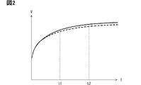
- the capacitance of the smoothing capacitor 440 decreases in this way, charging of the smoothing capacitor 440 can be completed quickly. For example, as shown in FIG. 2, the voltage change becomes faster when the smoothing capacitor 440 is charged.
- the vertical axis indicates voltage and the horizontal axis indicates time.
- Voltage is denoted by V.
- Time is denoted by T.
- a solid line indicates the voltage change of the deteriorated smoothing capacitor 440 .
- a dashed line indicates the voltage change of the undegraded smoothing capacitor 440 .
- the degraded smoothing capacitor 440 and the undegraded smoothing capacitor 440 have different voltages and different voltage changes over time (voltage changes).
- the voltage change of the degraded smoothing capacitor 440 during the transitional period (during charging) from the start to the end of charging is larger than the voltage change of the undegraded smoothing capacitor 440 .
- the capacitance of the smoothing capacitor 440 decreases, voltage smoothing by the smoothing capacitor 440 is impaired.
- the voltage of the fully charged smoothing capacitor 440 during use tends to fluctuate over time.
- the voltage change of the degraded smoothing capacitor 440 is greater than the voltage change of the undegraded smoothing capacitor 440 .
- the vertical axis indicates voltage and the horizontal axis indicates time. Voltage is denoted by V and time is denoted by T. A voltage change of the smoothing capacitor 440 that has deteriorated is indicated by a solid line, and a voltage change of the undegraded smoothing capacitor 440 is indicated by a broken line.
- the smoothing capacitor 440 when power conversion is performed in the power conversion device 400 by controlling switching of a plurality of switches included in the power conversion device 400 between an energized state and a cut-off state. be.
- the smoothing capacitor 440 is used is when the flow direction of the current flowing through the smoothing capacitor 440 changes on the order of microseconds due to power conversion. This is the time when the charge/discharge of the smoothing capacitor 440 changes on the order of microseconds due to power conversion.
- Reactor 420 has a winding core and windings.
- a winding wire is an insulated wire having a conductive wire and an insulating coating covering the conductive wire.
- Reactor 420 is configured by winding this winding around a winding core.
- the inductance of reactor 420 is proportional to the number of turns of this winding.
- a computing unit 408 of the EVECU 406 sequentially acquires the voltage of the smoothing capacitor 440 from the physical quantity sensor 403 in order to detect deterioration of the smoothing capacitor 440 and the reactor 420 .
- the calculation unit 408 calculates the time change (voltage change) of the voltage of the smoothing capacitor 440 .
- the calculation unit 408 sequentially acquires the temperature of the reactor 420 from the physical quantity sensor 403 .
- the calculation unit 408 calculates the time change (temperature change) of the temperature of the reactor 420 .
- the storage unit 407 of the EVECU 406 stores the charging determination value and the smoothing determination value as reference values.
- the charge determination value is determined based on the voltage change of smoothing capacitor 440 when non-degraded smoothing capacitor 440 is charged with power supply power of second battery 220 via non-degraded reactor 420 .
- the smoothing determination value is determined based on the voltage change of undegraded fully charged smoothing capacitor 440 when a plurality of switches included in converter 401 and inverter 402 are controlled to switch.
- At least one of the first temperature determination value and the second temperature determination value is stored in the storage unit 407 as a reference value.
- the first temperature determination value is determined based on the temperature change of undegraded reactor 420 during energization.
- the second temperature determination value is determined based on the durable temperature of reactor 420 .
- EVECU 406 corresponds to a deterioration determination device.
- Arithmetic unit 408 acquires a voltage change of smoothing capacitor 440 when smoothing capacitor 440 is charged. Then, the calculation unit 408 determines whether or not the voltage change is higher (faster) than the charge determination value. If the voltage change is higher than the charge determination value, calculation unit 408 determines that at least one of reactor 420 and smoothing capacitor 440 has deteriorated. When the voltage change is equal to or less than the charge determination value, calculation unit 408 determines that reactor 420 and smoothing capacitor 440 are normal.
- the voltage change is sharper at the start of charging than at the end of charging.
- the voltage change at time t1 is steeper than the voltage change at time t2.
- the voltage change is significantly different depending on time.
- the calculation unit 408 may calculate, for example, a voltage change at a time when charging of the smoothing capacitor 440 is expected to end (expected charging time), and compare the voltage change with the charge determination value. good.
- This expected charging time is determined based on the time required to charge the undegraded smoothing capacitor 440 .
- the expected charging time is stored in the storage unit 407 as a reference value.
- the charging determination value is determined based on the voltage change during this expected charging time.
- the expected charging time may be the time itself required for charging the undegraded smoothing capacitor 440, or may be shorter than that time.
- the expected charging time may be, for example, about 9/10 or 7/8 of that time.
- the calculation unit 408 acquires the voltage change of the fully charged smoothing capacitor 440 while driving the power conversion device 400 . Then, the calculation unit 408 determines whether or not the voltage change is higher (faster) than the smoothed determination value. When the voltage change is higher than the smoothing determination value, the calculation unit 408 determines that the smoothing capacitor 440 has deteriorated. If the voltage change is equal to or less than the smoothing determination value, the calculation unit 408 determines that the smoothing capacitor 440 is normal.
- the calculation unit 408 acquires the temperature change of the reactor 420 in the energized state. The calculation unit 408 determines whether the temperature change is higher (faster) than the first temperature determination value. If the temperature change is higher than the first temperature determination value, calculation unit 408 determines that reactor 420 has deteriorated. When the temperature change is equal to or less than the first temperature determination value, calculation unit 408 determines that reactor 420 is normal.
- the calculation unit 408 may, for example, calculate the temperature change of the reactor 420 when the temperature of the reactor 420 reaches or exceeds a predetermined temperature, and compare the temperature change with the first temperature determination value.
- This predetermined temperature is stored in the storage unit 407 as a reference value.
- calculation unit 408 may determine whether or not the temperature of the reactor 420 is higher than the second temperature determination value. If the temperature is higher than the second temperature determination value, calculation unit 408 determines that reactor 420 has deteriorated. When the temperature is equal to or lower than the second temperature determination value, calculation unit 408 determines that reactor 420 is normal.
- the second temperature determination value is a temperature higher than the predetermined temperature.
- step S10 the calculation unit 408 determines whether or not the smoothing capacitor 440 is in a charged state. If smoothing capacitor 440 is in a charged state, operation unit 408 proceeds to step S20. If smoothing capacitor 440 is not in a charged state, operation unit 408 proceeds to step S30.
- the calculation unit 408 controls charging of the smoothing capacitor 440 .
- the computing unit 408 acquires the charging start time. This charging start time is stored in the storage unit 407 .
- the calculation unit 408 acquires the voltage of the smoothing capacitor 440 from the physical quantity sensor 403. At this time, the calculation unit 408 detects the voltage at different times. Based on these multiple voltages, the calculation unit 408 calculates the voltage change of the smoothing capacitor 440 . After that, the calculation unit 408 proceeds to step S40.
- the calculation unit 408 may measure time from the charging start time of the smoothing capacitor 440 . Then, in step S20, the calculation unit 408 may calculate a voltage change after the charging expected time has elapsed from the charging start time.
- the calculation unit 408 determines whether or not the voltage change is greater than the charge determination value stored in the storage unit 407. If the voltage change is greater than the charge determination value, the calculation unit 408 proceeds to step S50. If the voltage change is equal to or less than the charging determination value, the calculation unit 408 proceeds to step S60.
- the calculation unit 408 determines that at least one of the reactor 420 and the smoothing capacitor 440 has deteriorated. The calculation unit 408 then stores the deterioration determination in the storage unit 407 . At the same time, the calculation unit 408 outputs the deterioration determination to the notification device of the electric vehicle. This notifies the user of the electric vehicle of the deterioration determination. After notification of the deterioration determination, the calculation unit 408 ends the deterioration determination process.
- the calculation unit 408 determines that the reactor 420 and the smoothing capacitor 440 are normal. Then, the calculation unit 408 stores the normality determination in the storage unit 407 . At the same time, the calculation unit 408 outputs the normality determination to the notification device. Thereby, the normal determination is notified to the user. After notification of the normality determination, the computing unit 408 terminates the deterioration determination process.
- step S10 when it is determined in step S10 that the smoothing capacitor 440 is not in a charged state and the process proceeds to step S30, the calculation unit 408 determines whether the power conversion device 400 is performing power conversion. That is, the calculation unit 408 determines whether or not the switch included in the power conversion device 400 is controlled to switch. When switching is controlled, the calculation unit 408 proceeds to step S70. If switching control is not performed, the calculation unit 408 terminates the deterioration determination process.
- the calculation unit 408 acquires the voltage of the smoothing capacitor 440 and the temperature of the reactor 420 from the physical quantity sensor 403. At this time, the calculation unit 408 detects voltage and temperature at different times. Based on this, the calculation unit 408 calculates voltage change and temperature change. After that, the calculation unit 408 proceeds to step S80.
- the temperature change may be calculated when the temperature of the reactor 420 reaches or exceeds a predetermined temperature. Moreover, when the deterioration determination of the reactor 420 is performed based on the temperature of the reactor 420, it is not necessary to calculate the temperature change.
- the calculation unit 408 determines whether or not the voltage change is greater than the smoothed determination value stored in the storage unit 407. If the voltage change is greater than the smoothing determination value, the calculation unit 408 proceeds to step S90. If the voltage change is equal to or less than the smoothing determination value, the calculation unit 408 proceeds to step S100.
- the calculation unit 408 determines that the smoothing capacitor 440 has deteriorated. Then, the calculation unit 408 stores the deterioration determination of the smoothing capacitor 440 in the storage unit 407 . At the same time, the calculation unit 408 outputs the deterioration determination of the smoothing capacitor 440 to the notification device. Thereby, the deterioration determination of the smoothing capacitor 440 is notified to the user. After this, the calculation unit 408 proceeds to step S110.
- the calculation unit 408 determines that the smoothing capacitor 440 is normal. Then, the calculation unit 408 stores the normality determination of the smoothing capacitor 440 in the storage unit 407 . At the same time, the calculation unit 408 outputs the normality determination of the smoothing capacitor 440 to the notification device. Thereby, the user is notified of the normality determination of the smoothing capacitor 440 . After this, the calculation unit 408 proceeds to step S110.
- the calculation unit 408 determines whether or not the temperature change or the temperature is greater than the first temperature determination value or the second temperature determination value stored in the storage unit 407 .
- the calculation unit 408 determines whether the temperature change is greater than the first temperature determination value.
- the calculation unit 408 determines whether the temperature is higher than the second temperature determination value.
- the temperature change and the temperature are collectively referred to as the temperature state, and the first temperature determination value and the second temperature determination value are collectively referred to as the temperature determination value. It is determined whether it is greater (higher) than If the temperature state is greater than the temperature judgment value, the calculation unit 408 proceeds to step S120. When the temperature state is equal to or lower than the temperature judgment value, the calculation unit 408 proceeds to step S130.
- the calculation unit 408 determines that the reactor 420 has deteriorated. Then, calculation unit 408 stores the deterioration determination of reactor 420 in storage unit 407 . At the same time, the calculation unit 408 outputs the deterioration determination of the reactor 420 to the notification device. Thereby, the deterioration determination of the reactor 420 is notified to the user. After the deterioration notification of the reactor 420, the calculation unit 408 ends the deterioration determination process.
- the calculation unit 408 determines that the reactor 420 is normal. Then, calculation unit 408 stores the normality determination of reactor 420 in storage unit 407 . At the same time, the calculation unit 408 outputs the normality determination of the reactor 420 to the notification device. This notifies the user of the normality determination of reactor 420 . After the reactor 420 is notified of normality, the calculation unit 408 terminates the deterioration determination process.
- the execution order of the state determination processing of the smoothing capacitor 440 in steps S80 to S100 and the state determination processing of the reactor 420 in steps S110 to S130 is not particularly limited. The execution order of these two types of state determination processing may be reversed from the execution order shown in FIG.
- the smoothing capacitor 440 is charged when the power conversion device 400 is not in use. After charging the smoothing capacitor 440, the power conversion device 400 is used. Therefore, after the processing of steps S20 and steps S40 to S60 shown in FIG. 4, the processing of steps S30 and steps S70 to S130 is executed. That is, after the combined deterioration determination of reactor 420 and smoothing capacitor 440, deterioration determination of reactor 420 and smoothing capacitor 440 is performed individually.
- step S50 when the deterioration determination in step S50 is performed, it is expected that at least one of step S90 and step S120 is performed. If the determination of normality in step S60 is performed, it is expected that steps S100 and S130 will each be performed.
- the computing unit 408 determines that the reliability of the deterioration determination and the normality determination is low. If the reliability of the determination is low, the calculation unit 408 may output a determination error display to the leaving device. This notifies the user of the determination error.
- the deterioration determination of reactor 420 may be performed when power conversion is not performed in power converter 400 .
- Deterioration determination of reactor 420 can be performed when current is flowing through reactor 420 .
- the deterioration determination of the reactor 420 may be performed after step S50 or step S60.
- the deterioration determination of reactor 420 may be performed while first SMR 310 and second SMR 320 are controlled to be energized in order to adjust the SOC of first battery 210 and second battery 220 .
- the calculation unit 408 may determine the drive limit of the power conversion device 400 .
- the drive limitation is, for example, the limitation of the amount of current applied to the power conversion device 400 and the applied voltage. Further, the calculation unit 408 may decide to strengthen the cooling of the power conversion device 400 by the cooler.
- calculation unit 408 determines that at least one of reactor 420 and smoothing capacitor 440 has deteriorated. Conversely, if the change in voltage of smoothing capacitor 440 during charging is equal to or less than the charge determination value, arithmetic unit 408 determines that reactor 420 and smoothing capacitor 440 are normal.
- the calculation unit 408 determines that the reactor 420 has deteriorated.
- the calculation unit 408 determines that the smoothing capacitor 440 has deteriorated.
- the deterioration of each of the reactor 420 and the smoothing capacitor 440 can be determined individually. Therefore, for example, if the reactor 420 and the smoothing capacitor 440 are individually replaceable modules from the power conversion device 400, only the faulty module can be replaced among these two modules.
- the deterioration determination of the reactor 420 and the smoothing capacitor 440 is performed based on the voltage change and the charge determination value when the smoothing capacitor 440 is charged.
- deterioration determination of the reactor 420 and the smoothing capacitor 440 is performed based on the charging time of the smoothing capacitor 440 .
- the computing unit 408 executes the deterioration determination process shown in FIG. While smoothing capacitor 440 is being charged, operation unit 408 executes steps S210 to S230 instead of step S40.
- the computing unit 408 acquires the voltage of the charged smoothing capacitor 440 at different times in step S20. Then, the calculation unit 408 calculates the voltage change. After that, the calculation unit 408 proceeds to step S210.
- the calculation unit 408 determines whether or not the voltage change has become smaller than a predetermined value. If the voltage change is not smaller than the predetermined value, the calculation unit 408 repeatedly executes steps S20 and S210. The calculation unit 408 enters a standby state. When the voltage change becomes smaller than the predetermined value because smoothing capacitor 440 is nearing a fully charged state, operation unit 408 proceeds to step S220.
- the predetermined value described above is a value larger than the voltage detection error.
- the predetermined value is a value for determining whether the smoothing capacitor 440 is fully charged.
- the predetermined value is stored in storage unit 407 as a reference value.
- the calculation unit 408 calculates the charging time of the smoothing capacitor 440 based on the time when the voltage change becomes smaller than a predetermined value and the charging start time of the smoothing capacitor 440. After that, the calculation unit 408 proceeds to step S230.
- the calculation unit 408 determines whether the charging time is shorter than the expected charging time. If the charging time is shorter than the expected charging time, the calculation unit 408 proceeds to step S50. If the charging time is equal to or longer than the expected charging time, the calculation unit 408 proceeds to step S60.
- the power conversion device 400 described in this embodiment includes components equivalent to the power conversion device 400 described in the first embodiment. Therefore, it goes without saying that the power conversion device 400 of the present embodiment has the same effect as the power conversion device 400 described in the first embodiment. Therefore, description thereof is omitted.
Landscapes
- Engineering & Computer Science (AREA)
- Power Engineering (AREA)
- Physics & Mathematics (AREA)
- General Physics & Mathematics (AREA)
- Inverter Devices (AREA)
- Testing Electric Properties And Detecting Electric Faults (AREA)
- Dc-Dc Converters (AREA)
Priority Applications (1)
| Application Number | Priority Date | Filing Date | Title |
|---|---|---|---|
| US18/476,850 US20240019503A1 (en) | 2021-04-02 | 2023-09-28 | Deterioration determination device, and power conversion device |
Applications Claiming Priority (2)
| Application Number | Priority Date | Filing Date | Title |
|---|---|---|---|
| JP2021063599A JP7494783B2 (ja) | 2021-04-02 | 2021-04-02 | 劣化判定装置、および、電力変換装置 |
| JP2021-063599 | 2021-04-02 |
Related Child Applications (1)
| Application Number | Title | Priority Date | Filing Date |
|---|---|---|---|
| US18/476,850 Continuation US20240019503A1 (en) | 2021-04-02 | 2023-09-28 | Deterioration determination device, and power conversion device |
Publications (1)
| Publication Number | Publication Date |
|---|---|
| WO2022209975A1 true WO2022209975A1 (ja) | 2022-10-06 |
Family
ID=83458787
Family Applications (1)
| Application Number | Title | Priority Date | Filing Date |
|---|---|---|---|
| PCT/JP2022/012375 Ceased WO2022209975A1 (ja) | 2021-04-02 | 2022-03-17 | 劣化判定装置、および、電力変換装置 |
Country Status (3)
| Country | Link |
|---|---|
| US (1) | US20240019503A1 (https=) |
| JP (1) | JP7494783B2 (https=) |
| WO (1) | WO2022209975A1 (https=) |
Families Citing this family (2)
| Publication number | Priority date | Publication date | Assignee | Title |
|---|---|---|---|---|
| DE112021006787T5 (de) * | 2021-01-12 | 2023-11-16 | Mitsubishi Electric Corporation | Spannungssensor und Leistungsumwandlungsvorrichtung |
| WO2024096055A1 (ja) * | 2022-11-04 | 2024-05-10 | 株式会社Gsユアサ | 電源機器の遠隔診断装置、遠隔診断システム及びコンピュータプログラム |
Citations (7)
| Publication number | Priority date | Publication date | Assignee | Title |
|---|---|---|---|---|
| JPH02266820A (ja) * | 1989-04-04 | 1990-10-31 | Fuji Electric Co Ltd | 電力変換装置用平滑コンデンサの寿命判定回路 |
| JPH05215800A (ja) * | 1992-02-04 | 1993-08-24 | Toyota Autom Loom Works Ltd | コンデンサの劣化診断方法 |
| JP2009189214A (ja) * | 2008-02-08 | 2009-08-20 | Toyota Motor Corp | 駆動装置およびこれが備えるコンデンサの異常判定方法 |
| JP2012115018A (ja) * | 2010-11-24 | 2012-06-14 | Toyota Motor Corp | 電力制御装置 |
| JP2012228965A (ja) * | 2011-04-26 | 2012-11-22 | Toyota Motor Corp | ハイブリッド車両の制御装置 |
| JP2018004523A (ja) * | 2016-07-06 | 2018-01-11 | 東洋電機製造株式会社 | コンデンサ状態判定装置 |
| WO2018216208A1 (ja) * | 2017-05-26 | 2018-11-29 | 三菱電機株式会社 | 電力変換装置 |
Family Cites Families (4)
| Publication number | Priority date | Publication date | Assignee | Title |
|---|---|---|---|---|
| WO2007029673A1 (ja) * | 2005-09-05 | 2007-03-15 | Matsushita Electric Industrial Co., Ltd. | 蓄電機器状態検出装置 |
| JP6195651B1 (ja) * | 2016-07-19 | 2017-09-13 | 三菱電機株式会社 | 電力変換装置、および電圧センサ特性の異常診断方法 |
| JP7038645B2 (ja) * | 2018-12-06 | 2022-03-18 | 三菱電機株式会社 | 半導体装置および半導体装置の製造方法 |
| JP7524565B2 (ja) * | 2020-03-18 | 2024-07-30 | 富士電機株式会社 | 電源装置および電源装置の劣化判定方法 |
-
2021
- 2021-04-02 JP JP2021063599A patent/JP7494783B2/ja active Active
-
2022
- 2022-03-17 WO PCT/JP2022/012375 patent/WO2022209975A1/ja not_active Ceased
-
2023
- 2023-09-28 US US18/476,850 patent/US20240019503A1/en active Pending
Patent Citations (7)
| Publication number | Priority date | Publication date | Assignee | Title |
|---|---|---|---|---|
| JPH02266820A (ja) * | 1989-04-04 | 1990-10-31 | Fuji Electric Co Ltd | 電力変換装置用平滑コンデンサの寿命判定回路 |
| JPH05215800A (ja) * | 1992-02-04 | 1993-08-24 | Toyota Autom Loom Works Ltd | コンデンサの劣化診断方法 |
| JP2009189214A (ja) * | 2008-02-08 | 2009-08-20 | Toyota Motor Corp | 駆動装置およびこれが備えるコンデンサの異常判定方法 |
| JP2012115018A (ja) * | 2010-11-24 | 2012-06-14 | Toyota Motor Corp | 電力制御装置 |
| JP2012228965A (ja) * | 2011-04-26 | 2012-11-22 | Toyota Motor Corp | ハイブリッド車両の制御装置 |
| JP2018004523A (ja) * | 2016-07-06 | 2018-01-11 | 東洋電機製造株式会社 | コンデンサ状態判定装置 |
| WO2018216208A1 (ja) * | 2017-05-26 | 2018-11-29 | 三菱電機株式会社 | 電力変換装置 |
Also Published As
| Publication number | Publication date |
|---|---|
| US20240019503A1 (en) | 2024-01-18 |
| JP2022158589A (ja) | 2022-10-17 |
| JP7494783B2 (ja) | 2024-06-04 |
Similar Documents
| Publication | Publication Date | Title |
|---|---|---|
| US11458844B2 (en) | Power supply system for vehicle | |
| US7269535B2 (en) | Fault diagnosing apparatus for vehicle and fault diagnosing method for vehicle | |
| JP4807058B2 (ja) | 車両用電源装置 | |
| CN102804574B (zh) | 转换器的输出二极管短路检测装置 | |
| US10202042B2 (en) | Electric vehicle power conversion system | |
| US7813849B2 (en) | Vehicle control system | |
| US20150331472A1 (en) | Dual power supply system and electrically driven vehicle | |
| US9843184B2 (en) | Voltage conversion apparatus | |
| CN104512275A (zh) | 电动车辆电力转换系统 | |
| JP2005114401A (ja) | 組電池の異常判定装置および組電池の異常判定方法 | |
| US20240019503A1 (en) | Deterioration determination device, and power conversion device | |
| CN113525126B (zh) | 用于车辆的充电系统及其电池充电停止方法 | |
| JP2020188610A (ja) | 駆動回路 | |
| JP6376422B2 (ja) | 充放電装置 | |
| JP5304279B2 (ja) | 蓄電装置 | |
| US10892635B2 (en) | Redundant power supply | |
| US12522085B2 (en) | Method and device for starting a vehicle electrical wiring system | |
| JP7528652B2 (ja) | 電源装置 | |
| JP2018165080A (ja) | 車両電源装置 | |
| JP7754347B2 (ja) | 電源システム及びプログラム | |
| JP7726415B2 (ja) | 電源システム及びプログラム | |
| JP7768428B2 (ja) | 電源システム及びプログラム | |
| JP2018011446A (ja) | 電源装置 | |
| JP7276080B2 (ja) | 異常判定装置 | |
| JP2020068605A (ja) | 車両用電源装置の診断装置 |
Legal Events
| Date | Code | Title | Description |
|---|---|---|---|
| 121 | Ep: the epo has been informed by wipo that ep was designated in this application |
Ref document number: 22780194 Country of ref document: EP Kind code of ref document: A1 |
|
| NENP | Non-entry into the national phase |
Ref country code: DE |
|
| 122 | Ep: pct application non-entry in european phase |
Ref document number: 22780194 Country of ref document: EP Kind code of ref document: A1 |