WO2022209739A1 - 熱源ユニットおよび冷凍装置 - Google Patents
熱源ユニットおよび冷凍装置 Download PDFInfo
- Publication number
- WO2022209739A1 WO2022209739A1 PCT/JP2022/010817 JP2022010817W WO2022209739A1 WO 2022209739 A1 WO2022209739 A1 WO 2022209739A1 JP 2022010817 W JP2022010817 W JP 2022010817W WO 2022209739 A1 WO2022209739 A1 WO 2022209739A1
- Authority
- WO
- WIPO (PCT)
- Prior art keywords
- refrigerant
- source unit
- heat source
- cooler
- outdoor
- Prior art date
Links
- 238000005057 refrigeration Methods 0.000 title claims description 95
- 239000003507 refrigerant Substances 0.000 claims abstract description 527
- 239000002826 coolant Substances 0.000 claims abstract description 29
- 238000001816 cooling Methods 0.000 claims description 176
- 230000000284 resting effect Effects 0.000 claims description 19
- 230000006837 decompression Effects 0.000 claims description 7
- 239000007788 liquid Substances 0.000 description 49
- 238000000034 method Methods 0.000 description 43
- 230000008569 process Effects 0.000 description 43
- 238000004378 air conditioning Methods 0.000 description 40
- 238000010438 heat treatment Methods 0.000 description 33
- 238000002347 injection Methods 0.000 description 24
- 239000007924 injection Substances 0.000 description 24
- 238000004891 communication Methods 0.000 description 22
- 230000006835 compression Effects 0.000 description 21
- 238000007906 compression Methods 0.000 description 21
- CURLTUGMZLYLDI-UHFFFAOYSA-N Carbon dioxide Chemical compound O=C=O CURLTUGMZLYLDI-UHFFFAOYSA-N 0.000 description 18
- 238000010586 diagram Methods 0.000 description 14
- 238000012986 modification Methods 0.000 description 12
- 238000012545 processing Methods 0.000 description 12
- 230000007246 mechanism Effects 0.000 description 11
- 239000012071 phase Substances 0.000 description 11
- 229910002092 carbon dioxide Inorganic materials 0.000 description 9
- 239000001569 carbon dioxide Substances 0.000 description 9
- 230000004048 modification Effects 0.000 description 9
- 230000008859 change Effects 0.000 description 8
- 238000004781 supercooling Methods 0.000 description 7
- 102100036848 C-C motif chemokine 20 Human genes 0.000 description 4
- 230000007423 decrease Effects 0.000 description 4
- 239000013256 coordination polymer Substances 0.000 description 3
- 239000004065 semiconductor Substances 0.000 description 3
- ATUOYWHBWRKTHZ-UHFFFAOYSA-N Propane Chemical compound CCC ATUOYWHBWRKTHZ-UHFFFAOYSA-N 0.000 description 2
- 230000009471 action Effects 0.000 description 2
- 238000006073 displacement reaction Methods 0.000 description 2
- 239000007791 liquid phase Substances 0.000 description 2
- 239000000203 mixture Substances 0.000 description 2
- 101000760620 Homo sapiens Cell adhesion molecule 1 Proteins 0.000 description 1
- 101000911772 Homo sapiens Hsc70-interacting protein Proteins 0.000 description 1
- 239000000498 cooling water Substances 0.000 description 1
- 239000012530 fluid Substances 0.000 description 1
- 230000001771 impaired effect Effects 0.000 description 1
- 239000001294 propane Substances 0.000 description 1
- 229920006395 saturated elastomer Polymers 0.000 description 1
- 239000011555 saturated liquid Substances 0.000 description 1
- 238000010257 thawing Methods 0.000 description 1
- 238000012546 transfer Methods 0.000 description 1
- 238000010792 warming Methods 0.000 description 1
Images


Classifications
-
- F—MECHANICAL ENGINEERING; LIGHTING; HEATING; WEAPONS; BLASTING
- F25—REFRIGERATION OR COOLING; COMBINED HEATING AND REFRIGERATION SYSTEMS; HEAT PUMP SYSTEMS; MANUFACTURE OR STORAGE OF ICE; LIQUEFACTION SOLIDIFICATION OF GASES
- F25B—REFRIGERATION MACHINES, PLANTS OR SYSTEMS; COMBINED HEATING AND REFRIGERATION SYSTEMS; HEAT PUMP SYSTEMS
- F25B7/00—Compression machines, plants or systems, with cascade operation, i.e. with two or more circuits, the heat from the condenser of one circuit being absorbed by the evaporator of the next circuit
-
- F—MECHANICAL ENGINEERING; LIGHTING; HEATING; WEAPONS; BLASTING
- F25—REFRIGERATION OR COOLING; COMBINED HEATING AND REFRIGERATION SYSTEMS; HEAT PUMP SYSTEMS; MANUFACTURE OR STORAGE OF ICE; LIQUEFACTION SOLIDIFICATION OF GASES
- F25B—REFRIGERATION MACHINES, PLANTS OR SYSTEMS; COMBINED HEATING AND REFRIGERATION SYSTEMS; HEAT PUMP SYSTEMS
- F25B49/00—Arrangement or mounting of control or safety devices
- F25B49/02—Arrangement or mounting of control or safety devices for compression type machines, plants or systems
-
- F—MECHANICAL ENGINEERING; LIGHTING; HEATING; WEAPONS; BLASTING
- F25—REFRIGERATION OR COOLING; COMBINED HEATING AND REFRIGERATION SYSTEMS; HEAT PUMP SYSTEMS; MANUFACTURE OR STORAGE OF ICE; LIQUEFACTION SOLIDIFICATION OF GASES
- F25B—REFRIGERATION MACHINES, PLANTS OR SYSTEMS; COMBINED HEATING AND REFRIGERATION SYSTEMS; HEAT PUMP SYSTEMS
- F25B1/00—Compression machines, plants or systems with non-reversible cycle
- F25B1/04—Compression machines, plants or systems with non-reversible cycle with compressor of rotary type
-
- F—MECHANICAL ENGINEERING; LIGHTING; HEATING; WEAPONS; BLASTING
- F25—REFRIGERATION OR COOLING; COMBINED HEATING AND REFRIGERATION SYSTEMS; HEAT PUMP SYSTEMS; MANUFACTURE OR STORAGE OF ICE; LIQUEFACTION SOLIDIFICATION OF GASES
- F25B—REFRIGERATION MACHINES, PLANTS OR SYSTEMS; COMBINED HEATING AND REFRIGERATION SYSTEMS; HEAT PUMP SYSTEMS
- F25B1/00—Compression machines, plants or systems with non-reversible cycle
- F25B1/10—Compression machines, plants or systems with non-reversible cycle with multi-stage compression
-
- F—MECHANICAL ENGINEERING; LIGHTING; HEATING; WEAPONS; BLASTING
- F25—REFRIGERATION OR COOLING; COMBINED HEATING AND REFRIGERATION SYSTEMS; HEAT PUMP SYSTEMS; MANUFACTURE OR STORAGE OF ICE; LIQUEFACTION SOLIDIFICATION OF GASES
- F25B—REFRIGERATION MACHINES, PLANTS OR SYSTEMS; COMBINED HEATING AND REFRIGERATION SYSTEMS; HEAT PUMP SYSTEMS
- F25B13/00—Compression machines, plants or systems, with reversible cycle
-
- F—MECHANICAL ENGINEERING; LIGHTING; HEATING; WEAPONS; BLASTING
- F25—REFRIGERATION OR COOLING; COMBINED HEATING AND REFRIGERATION SYSTEMS; HEAT PUMP SYSTEMS; MANUFACTURE OR STORAGE OF ICE; LIQUEFACTION SOLIDIFICATION OF GASES
- F25B—REFRIGERATION MACHINES, PLANTS OR SYSTEMS; COMBINED HEATING AND REFRIGERATION SYSTEMS; HEAT PUMP SYSTEMS
- F25B40/00—Subcoolers, desuperheaters or superheaters
- F25B40/02—Subcoolers
-
- F—MECHANICAL ENGINEERING; LIGHTING; HEATING; WEAPONS; BLASTING
- F25—REFRIGERATION OR COOLING; COMBINED HEATING AND REFRIGERATION SYSTEMS; HEAT PUMP SYSTEMS; MANUFACTURE OR STORAGE OF ICE; LIQUEFACTION SOLIDIFICATION OF GASES
- F25B—REFRIGERATION MACHINES, PLANTS OR SYSTEMS; COMBINED HEATING AND REFRIGERATION SYSTEMS; HEAT PUMP SYSTEMS
- F25B40/00—Subcoolers, desuperheaters or superheaters
- F25B40/06—Superheaters
-
- F—MECHANICAL ENGINEERING; LIGHTING; HEATING; WEAPONS; BLASTING
- F25—REFRIGERATION OR COOLING; COMBINED HEATING AND REFRIGERATION SYSTEMS; HEAT PUMP SYSTEMS; MANUFACTURE OR STORAGE OF ICE; LIQUEFACTION SOLIDIFICATION OF GASES
- F25B—REFRIGERATION MACHINES, PLANTS OR SYSTEMS; COMBINED HEATING AND REFRIGERATION SYSTEMS; HEAT PUMP SYSTEMS
- F25B41/00—Fluid-circulation arrangements
- F25B41/20—Disposition of valves, e.g. of on-off valves or flow control valves
-
- F—MECHANICAL ENGINEERING; LIGHTING; HEATING; WEAPONS; BLASTING
- F25—REFRIGERATION OR COOLING; COMBINED HEATING AND REFRIGERATION SYSTEMS; HEAT PUMP SYSTEMS; MANUFACTURE OR STORAGE OF ICE; LIQUEFACTION SOLIDIFICATION OF GASES
- F25B—REFRIGERATION MACHINES, PLANTS OR SYSTEMS; COMBINED HEATING AND REFRIGERATION SYSTEMS; HEAT PUMP SYSTEMS
- F25B2313/00—Compression machines, plants or systems with reversible cycle not otherwise provided for
- F25B2313/023—Compression machines, plants or systems with reversible cycle not otherwise provided for using multiple indoor units
- F25B2313/0233—Compression machines, plants or systems with reversible cycle not otherwise provided for using multiple indoor units in parallel arrangements
-
- F—MECHANICAL ENGINEERING; LIGHTING; HEATING; WEAPONS; BLASTING
- F25—REFRIGERATION OR COOLING; COMBINED HEATING AND REFRIGERATION SYSTEMS; HEAT PUMP SYSTEMS; MANUFACTURE OR STORAGE OF ICE; LIQUEFACTION SOLIDIFICATION OF GASES
- F25B—REFRIGERATION MACHINES, PLANTS OR SYSTEMS; COMBINED HEATING AND REFRIGERATION SYSTEMS; HEAT PUMP SYSTEMS
- F25B2313/00—Compression machines, plants or systems with reversible cycle not otherwise provided for
- F25B2313/025—Compression machines, plants or systems with reversible cycle not otherwise provided for using multiple outdoor units
- F25B2313/0254—Compression machines, plants or systems with reversible cycle not otherwise provided for using multiple outdoor units in series arrangements
-
- F—MECHANICAL ENGINEERING; LIGHTING; HEATING; WEAPONS; BLASTING
- F25—REFRIGERATION OR COOLING; COMBINED HEATING AND REFRIGERATION SYSTEMS; HEAT PUMP SYSTEMS; MANUFACTURE OR STORAGE OF ICE; LIQUEFACTION SOLIDIFICATION OF GASES
- F25B—REFRIGERATION MACHINES, PLANTS OR SYSTEMS; COMBINED HEATING AND REFRIGERATION SYSTEMS; HEAT PUMP SYSTEMS
- F25B2313/00—Compression machines, plants or systems with reversible cycle not otherwise provided for
- F25B2313/027—Compression machines, plants or systems with reversible cycle not otherwise provided for characterised by the reversing means
- F25B2313/02732—Compression machines, plants or systems with reversible cycle not otherwise provided for characterised by the reversing means using two three-way valves
-
- F—MECHANICAL ENGINEERING; LIGHTING; HEATING; WEAPONS; BLASTING
- F25—REFRIGERATION OR COOLING; COMBINED HEATING AND REFRIGERATION SYSTEMS; HEAT PUMP SYSTEMS; MANUFACTURE OR STORAGE OF ICE; LIQUEFACTION SOLIDIFICATION OF GASES
- F25B—REFRIGERATION MACHINES, PLANTS OR SYSTEMS; COMBINED HEATING AND REFRIGERATION SYSTEMS; HEAT PUMP SYSTEMS
- F25B2400/00—General features or devices for refrigeration machines, plants or systems, combined heating and refrigeration systems or heat-pump systems, i.e. not limited to a particular subgroup of F25B
- F25B2400/04—Refrigeration circuit bypassing means
- F25B2400/0401—Refrigeration circuit bypassing means for the compressor
-
- F—MECHANICAL ENGINEERING; LIGHTING; HEATING; WEAPONS; BLASTING
- F25—REFRIGERATION OR COOLING; COMBINED HEATING AND REFRIGERATION SYSTEMS; HEAT PUMP SYSTEMS; MANUFACTURE OR STORAGE OF ICE; LIQUEFACTION SOLIDIFICATION OF GASES
- F25B—REFRIGERATION MACHINES, PLANTS OR SYSTEMS; COMBINED HEATING AND REFRIGERATION SYSTEMS; HEAT PUMP SYSTEMS
- F25B2400/00—General features or devices for refrigeration machines, plants or systems, combined heating and refrigeration systems or heat-pump systems, i.e. not limited to a particular subgroup of F25B
- F25B2400/07—Details of compressors or related parts
- F25B2400/072—Intercoolers therefor
-
- F—MECHANICAL ENGINEERING; LIGHTING; HEATING; WEAPONS; BLASTING
- F25—REFRIGERATION OR COOLING; COMBINED HEATING AND REFRIGERATION SYSTEMS; HEAT PUMP SYSTEMS; MANUFACTURE OR STORAGE OF ICE; LIQUEFACTION SOLIDIFICATION OF GASES
- F25B—REFRIGERATION MACHINES, PLANTS OR SYSTEMS; COMBINED HEATING AND REFRIGERATION SYSTEMS; HEAT PUMP SYSTEMS
- F25B2400/00—General features or devices for refrigeration machines, plants or systems, combined heating and refrigeration systems or heat-pump systems, i.e. not limited to a particular subgroup of F25B
- F25B2400/13—Economisers
-
- F—MECHANICAL ENGINEERING; LIGHTING; HEATING; WEAPONS; BLASTING
- F25—REFRIGERATION OR COOLING; COMBINED HEATING AND REFRIGERATION SYSTEMS; HEAT PUMP SYSTEMS; MANUFACTURE OR STORAGE OF ICE; LIQUEFACTION SOLIDIFICATION OF GASES
- F25B—REFRIGERATION MACHINES, PLANTS OR SYSTEMS; COMBINED HEATING AND REFRIGERATION SYSTEMS; HEAT PUMP SYSTEMS
- F25B2400/00—General features or devices for refrigeration machines, plants or systems, combined heating and refrigeration systems or heat-pump systems, i.e. not limited to a particular subgroup of F25B
- F25B2400/23—Separators
-
- F—MECHANICAL ENGINEERING; LIGHTING; HEATING; WEAPONS; BLASTING
- F25—REFRIGERATION OR COOLING; COMBINED HEATING AND REFRIGERATION SYSTEMS; HEAT PUMP SYSTEMS; MANUFACTURE OR STORAGE OF ICE; LIQUEFACTION SOLIDIFICATION OF GASES
- F25B—REFRIGERATION MACHINES, PLANTS OR SYSTEMS; COMBINED HEATING AND REFRIGERATION SYSTEMS; HEAT PUMP SYSTEMS
- F25B2600/00—Control issues
- F25B2600/25—Control of valves
- F25B2600/2513—Expansion valves
-
- F—MECHANICAL ENGINEERING; LIGHTING; HEATING; WEAPONS; BLASTING
- F25—REFRIGERATION OR COOLING; COMBINED HEATING AND REFRIGERATION SYSTEMS; HEAT PUMP SYSTEMS; MANUFACTURE OR STORAGE OF ICE; LIQUEFACTION SOLIDIFICATION OF GASES
- F25B—REFRIGERATION MACHINES, PLANTS OR SYSTEMS; COMBINED HEATING AND REFRIGERATION SYSTEMS; HEAT PUMP SYSTEMS
- F25B2700/00—Sensing or detecting of parameters; Sensors therefor
- F25B2700/21—Temperatures
- F25B2700/2104—Temperatures of an indoor room or compartment
-
- F—MECHANICAL ENGINEERING; LIGHTING; HEATING; WEAPONS; BLASTING
- F25—REFRIGERATION OR COOLING; COMBINED HEATING AND REFRIGERATION SYSTEMS; HEAT PUMP SYSTEMS; MANUFACTURE OR STORAGE OF ICE; LIQUEFACTION SOLIDIFICATION OF GASES
- F25B—REFRIGERATION MACHINES, PLANTS OR SYSTEMS; COMBINED HEATING AND REFRIGERATION SYSTEMS; HEAT PUMP SYSTEMS
- F25B2700/00—Sensing or detecting of parameters; Sensors therefor
- F25B2700/21—Temperatures
- F25B2700/2117—Temperatures of an evaporator
- F25B2700/21174—Temperatures of an evaporator of the refrigerant at the inlet of the evaporator
-
- F—MECHANICAL ENGINEERING; LIGHTING; HEATING; WEAPONS; BLASTING
- F25—REFRIGERATION OR COOLING; COMBINED HEATING AND REFRIGERATION SYSTEMS; HEAT PUMP SYSTEMS; MANUFACTURE OR STORAGE OF ICE; LIQUEFACTION SOLIDIFICATION OF GASES
- F25B—REFRIGERATION MACHINES, PLANTS OR SYSTEMS; COMBINED HEATING AND REFRIGERATION SYSTEMS; HEAT PUMP SYSTEMS
- F25B2700/00—Sensing or detecting of parameters; Sensors therefor
- F25B2700/21—Temperatures
- F25B2700/2117—Temperatures of an evaporator
- F25B2700/21175—Temperatures of an evaporator of the refrigerant at the outlet of the evaporator
Definitions
- a fifteenth aspect of the present disclosure is a refrigeration system (1) comprising a heat source unit (10) according to any one of the first to fourteenth aspects and a utilization unit connected to the heat source unit (10) (50,60).
- Embodiment 1 will be described.
- the refrigeration system (1) of the present embodiment can cool an object to be cooled and air-condition the room.
- the object to be cooled includes the air in facilities such as refrigerators, freezers, and showcases.
- the refrigerator (1) includes a heat source unit (10) installed outdoors, an air conditioning unit (50) for air conditioning the room, and a cooling unit (60) for cooling the air inside the refrigerator.
- a refrigerating apparatus (1) of this embodiment includes one main unit (10a), a plurality of cooling units (60), and a plurality of air conditioning units (50).
- the heat source unit (10) also includes a main unit (10a) and an auxiliary unit (150).
- the number of cooling units (60) or air conditioning units (50) included in the refrigeration system (1) may be one.
- Compression element (C) compresses the primary refrigerant.
- the compression element (C) has a high stage compressor (21), a first low stage compressor (23) and a second low stage compressor (22).
- the high-stage compressor (21), the first low-stage compressor (23), and the second low-stage compressor (22) are rotary compressors whose compression mechanisms are driven by motors.
- the high-stage compressor (21), the first low-stage compressor (23), and the second low-stage compressor (22) are configured as variable displacement compressors in which the rotation speed of the compression mechanism can be changed.
- the first port of the second switching valve (82) is connected to the outflow end of the second pipe (32).
- a second port of the second switching valve (82) is connected to the inflow end of the fourth pipe (34).
- a third port of the second switching valve (82) is connected to the second outdoor gas pipe (36).
- a fourth port of the second switching valve (82) is sealed.
- the gas vent pipe (37) is a gas pipe for sending the gas refrigerant of the receiver (15) to the high-stage suction pipe (21a). Specifically, one end of the gas vent pipe (37) is connected to the top of the receiver (15). The other end of the gas vent pipe (37) is connected to the middle of the injection pipe (38). A gas vent valve (39) is connected to the gas vent pipe (37).
- the gas vent valve (39) is an electronic expansion valve with a variable degree of opening.
- the gas vent valve (39) is a decompression section that decompresses the refrigerant flowing through the gas vent pipe (37).
- the outdoor circuit (11) has a subcooling heat exchanger (16).
- the subcooling heat exchanger (16) is a first cooler that cools the primary refrigerant (mainly liquid refrigerant) flowing out from the receiver (15).
- a subcooling heat exchanger (16) is provided downstream of the receiver (15).
- the subcooling heat exchanger (16) has a first flow path (16a) and a second flow path (16b). The subcooling heat exchanger (16) exchanges heat between the primary refrigerant flowing through the first flow path (16a) and the primary refrigerant flowing through the second flow path (16b).
- the outdoor controller (101) includes a microcomputer mounted on a control board and a memory device storing software for operating the microcomputer.
- the memory device is a semiconductor memory.
- the outdoor controller (101) controls the components of the main unit (10a).
- a cooling unit (60) is a utilization unit installed indoors.
- the cooling unit (60) is, for example, a refrigerated showcase installed in a store such as a convenience store.
- the cooling unit (60) may be a unit cooler that cools the air inside the refrigerator.
- the first switching valve (81) and the second switching valve (82) are set to the first state.
- the first low-stage compressor (23), the second low-stage compressor (22), and the high-stage compressor (21) operate.
- a refrigeration cycle is performed by circulating the primary refrigerant in the refrigerant circuit (6), the outdoor heat exchanger (13) functions as a radiator (gas cooler), and the cooling heat exchanger (64) and the indoor heat An exchanger (54) functions as an evaporator.
- the primary refrigerant that has flowed into the injection pipe (38) is decompressed when passing through the injection valve (40).
- the primary refrigerant (state of point F in FIG. 4) flows into the second flow path (16b) of the supercooling heat exchanger (16) and flows through the first flow path (16a). It absorbs heat from the primary refrigerant and evaporates.
- the primary refrigerant that has flowed out of the second flow path (16b) of the subcooling heat exchanger (16) (state of point G in FIG. 4) flows into the high-stage suction pipe (21a).
- the refrigerant temperature sensor (157) is provided in the first outdoor pipe (o1).
- the refrigerant temperature sensor (157) is provided in a portion of the first outdoor pipe (o1) between the refrigerant cooler (155) and the outdoor expansion valve (14), and measures the temperature of refrigerant flowing through this portion.
- the measured value of the refrigerant temperature sensor (157) is transmitted to the outdoor controller (101).
- the second flow path (155b) of the refrigerant cooler (155) is provided in the first low-stage suction pipe (23a).
- refrigerant flowing through the first low-stage suction pipe (23a) toward the first low-stage compressor (23) flows as a cooling medium through the second flow path (155b). .
- a bypass valve (166) is provided in the bypass pipe (165).
- the bypass valve (166) is an on-off valve composed of an electromagnetic valve.
- the bypass valve (166) is configured to interrupt both the flow of refrigerant from one end of the bypass pipe (165) to the other end and the flow of refrigerant from the other end to the other end of the bypass pipe (165).
- the bypass pipe (165), the bypass valve (166), and the outdoor on-off valve (161) switch the refrigerant cooler (155) between the cooling state and the resting state.
- the bypass valve (166) is closed and the outdoor on-off valve (161) is open, refrigerant flows through the first flow path (155a) of the refrigerant cooler (155), and the refrigerant cooler (155) is cooled.
- the bypass valve (166) is open and the outdoor on-off valve (161) is closed, the refrigerant flows through the bypass pipe (165) and the refrigerant cooler (155) is inactive.
- the refrigeration system (1) of the present embodiment performs a cooling operation and a heating operation, like the refrigeration system (1) of the first embodiment.
- the refrigerant cooler (155) is in a resting state during the heating operation.
- the controller (100) closes the outdoor on-off valve (161) and opens the bypass valve (166), the refrigerant cooler (155) is inactive.
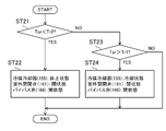
- the control operation of this outdoor controller (101) will be described with reference to the flowchart of FIG.
- the outdoor controller (101) repeatedly executes the control operation shown in the flow chart of FIG. 10 every predetermined time (for example, every 60 seconds).
- the first reference temperature Tr1 and the second reference temperature Tr2 in the outdoor controller (101) of the present embodiment are the same as the first reference temperature Tr1 and the second reference temperature Tr2 of the first embodiment, respectively.
- the cooling unit (60) of the second embodiment is omitted from the refrigeration system (1) of the present embodiment.
- the refrigerant circuit (6) of the refrigeration system (1) of the present embodiment one heat source unit (10) and a plurality of air conditioning units (50) are connected to the first liquid communication pipe (2) and the second gas communication pipe. Connected by (5).
- the heat source unit (10) of this embodiment includes one switching valve (80) instead of the channel switching mechanism (30) of the second embodiment.
- the switching valve (80) is a four-way switching valve, like the first switching valve (81) and the second switching valve (82) of the second embodiment.
- the switching valve (80) has a first port connected to the high-stage discharge pipe (21b), a second port connected to the first low-stage suction pipe (23a), a third port connected to the second outdoor gas pipe (36), and a third port connected to the second outdoor gas pipe (36). Four ports are connected to the first outdoor gas pipe (35) respectively.
- the controller (100) of this modification controls the switching section (170) so that the refrigerant cooler (155) changes from the rest state to the cooling state when the first condition regarding the operating capacity of the compression element (C) is satisfied. do.
- the first condition is, for example, that the rotation speed of the high-stage compressor (21) reaches a first reference speed (for example, maximum rotation speed) and the rotation speed of the first low-stage compressor (23) reaches a second reference speed ( For example, the maximum rotation speed) is reached, and the rotation speed of the second low-stage compressor (22) reaches a third reference speed (eg, maximum rotation speed).
- An example of the second reference temperature Tr2 when the primary refrigerant is carbon dioxide is "32°C".
- the first reference temperature Tr1 is also a constant value.
- the values of the first reference temperature Tr1 and the second reference temperature Tr2 shown here are merely examples. Therefore, for example, the second reference temperature Tr2 may be set at "29°C" and the first reference temperature Tr1 may be set at "37°C".
Abstract
Description
実施形態1について説明する。本実施形態の冷凍装置(1)は、冷却対象の冷却と、室内の空気調和と行うことができる。ここでいう冷却対象は、冷蔵庫、冷凍庫、ショーケースなどの設備内の空気を含む。
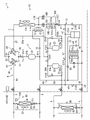
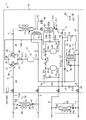
図1に示すように、冷凍装置(1)は、室外に設置される熱源ユニット(10)と、室内の空調を行う空調ユニット(50)と、庫内の空気を冷却する冷却ユニット(60)とを備える。本実施形態の冷凍装置(1)は、一台の本体ユニット(10a)と、複数台の冷却ユニット(60)と、複数台の空調ユニット(50)とを備える。また、熱源ユニット(10)は、本体ユニット(10a)と、補助ユニット(150)とを備える。なお、冷凍装置(1)が備える冷却ユニット(60)又は空調ユニット(50)の台数は、一台であってもよい。
上述したように、熱源ユニット(10)は、本体ユニット(10a)と、補助ユニット(150)とを備える。本体ユニット(10a)と補助ユニット(150)は、第1接続管(191)及び第2接続管(192)によって接続される。本体ユニット(10a)及び補助ユニット(150)は、屋外に設置される。
本体ユニット(10a)は、室外ファン(12)と、室外回路(11)とを有する。室外回路(11)は、圧縮要素(C)、流路切換機構(30)、室外熱交換器(13)、室外膨張弁(14)、レシーバ(15)、過冷却熱交換器(16)、及び中間冷却器(17)を有する。また、本体ユニット(10a)は、室外制御器(101)を有する。
圧縮要素(C)は、一次冷媒を圧縮する。圧縮要素(C)は、高段圧縮機(21)、第1低段圧縮機(23)、及び第2低段圧縮機(22)を有する。高段圧縮機(21)、第1低段圧縮機(23)、及び第2低段圧縮機(22)は、モータによって圧縮機構が駆動される回転式圧縮機である。高段圧縮機(21)、第1低段圧縮機(23)、及び第2低段圧縮機(22)は、圧縮機構の回転速度が変更可能な可変容量式に構成される。
流路切換機構(30)は、冷媒回路(6)における一次冷媒の流通経路を切り換える機構である。流路切換機構(30)は、第1配管(31)、第2配管(32)、第3配管(33)、第4配管(34)、第1切換弁(81)、及び第2切換弁(82)を有する。
室外熱交換器(13)は、第1熱交換器を構成している。室外熱交換器(13)は、フィン・アンド・チューブ型の空気熱交換器である。室外ファン(12)は、室外熱交換器(13)の近傍に配置される。室外ファン(12)は、室外空気を搬送する。室外熱交換器(13)は、その内部を流れる一次冷媒と、室外ファン(12)が搬送する室外空気とを熱交換させる。
室外流路(O)は、室外第1管(o1)、室外第2管(o2)、室外第3管(o3)、室外第4管(o4)、室外第5管(o5)、室外第6管(o6)、室外第7管(o7)、及び室外第8管(o8)を含む。
室外回路(11)の室外第1管(o1)には、室外膨張弁(14)が設けられる。本実施形態の室外第1管(o1)では、第2部分管(o1B)に室外膨張弁(14)が設けられる。室外膨張弁(14)は、開度を調節可能な電子膨張弁である。室外膨張弁(14)は、第1膨張弁を構成する。
レシーバ(15)は、一次冷媒を貯留する容器を構成している。レシーバ(15)は、室外膨張弁(14)の下流に設けられる。レシーバ(15)では、ガス冷媒と液冷媒が共存する。レシーバ(15)の頂部には、室外第2管(o2)の他端と、後述するガス抜き管(37)の一端が接続される。
室外回路(11)は、中間インジェクション回路(49)を備える。中間インジェクション回路(49)は、室外膨張弁(14)により減圧された一次冷媒を、高段吸入管(21a)へ供給する回路である。中間インジェクション回路(49)は、ガス抜き管(37)及びインジェクション管(38)を備える。
室外回路(11)は、過冷却熱交換器(16)を備える。過冷却熱交換器(16)は、レシーバ(15)から流出した一次冷媒(主として液冷媒)を冷却する第1冷却器である。過冷却熱交換器(16)は、レシーバ(15)の下流に設けられる。過冷却熱交換器(16)は、第1流路(16a)と第2流路(16b)とを有する。過冷却熱交換器(16)は、第1流路(16a)を流れる一次冷媒と、第2流路(16b)を流れる一次冷媒とを熱交換させる。
中間冷却器(17)は、中間流路(41)に接続される。中間流路(41)の一端は、第1低段吐出管(23b)及び第2低段吐出管(22b)に接続される。中間流路(41)の他端は、高段吸入管(21a)に接続される。
室外回路(11)は、第1逆止弁(CV1)、第2逆止弁(CV2)、第3逆止弁(CV3)、第4逆止弁(CV4)、第5逆止弁(CV5)、第6逆止弁(CV6)、第7逆止弁(CV7)、第8逆止弁(CV8)、及び第9逆止弁(CV9)を有する。これらの逆止弁(CV1~CV9)は、図1に示す矢印方向の一次冷媒の流れを許容し、この矢印と反対方向の一次冷媒の流れを禁止する。
本体ユニット(10a)は、各種のセンサを有する。各種のセンサは、高圧圧力センサ(71)、中間圧圧力センサ(72)、第1低圧圧力センサ(74)、第2低圧圧力センサ(73)、及び液冷媒圧力センサ(75)を含む。本体ユニット(10a)に設けられたセンサの計測値は、室外制御器(101)に送信される。
図2に示すように、室外制御器(101)は、制御基板上に搭載されたマイクロコンピュータと、マイクロコンピュータを動作させるためのソフトウエアを格納するメモリデバイスとを含む。メモリデバイスは、半導体メモリである。室外制御器(101)は、本体ユニット(10a)の構成機器を制御する。
補助ユニット(150)は、補助冷媒回路(151)と、補助ファン(156)と、冷媒温度センサ(157)と、補助制御器(102)とを備える。補助ユニット(150)は、第1接続管(191)を介して本体ユニット(10a)の第1接続ポート(181)に接続され、第2接続管(192)を介して本体ユニット(10a)の第2接続ポート(182)に接続される。
補助圧縮機(152)は、モータによって圧縮機構が駆動される回転式圧縮機である。補助圧縮機(152)は、圧縮機構の回転速度が変更可能な可変容量式に構成される。補助圧縮機(152)は、二次冷媒を吸入して圧縮し、圧縮した二次冷媒を吐出する。補助圧縮機(152)は、冷媒冷却器(155)を冷却状態と休止状態とに相互に切り換える切換部(170)を構成する。
補助室外熱交換器(153)は、フィン・アンド・チューブ型の空気熱交換器である。補助ファン(156)は、補助室外熱交換器(153)の近傍に配置される。補助ファン(156)は、室外空気を搬送する。補助室外熱交換器(153)は、その内部を流れる二次冷媒と、補助ファン(156)が搬送する室外空気とを熱交換させる。
補助膨張弁(154)は、開度を調節可能な電子膨張弁である。補助膨張弁(154)は、補助室外熱交換器(153)から冷媒冷却器(155)へ向かう二次冷媒を減圧する。
冷媒冷却器(155)は、第1流路(155a)と第2流路(155b)とを備える熱交換器である。
冷媒温度センサ(157)は、冷媒冷却器(155)の第1流路(155a)と第2接続管(192)を繋ぐ配管に取り付けられる。冷媒温度センサ(157)は、この配管を流れる一次冷媒の温度を計測する。冷媒温度センサ(157)の計測値は、補助制御器(102)へ送信される。
図2に示すように、補助制御器(102)は、制御基板上に搭載されたマイクロコンピュータと、マイクロコンピュータを動作させるためのソフトウエアを格納するメモリデバイスとを含む。メモリデバイスは、半導体メモリである。補助制御器(102)には、補助制御器(102)は、補助圧縮機(152)、補助膨張弁(154)、及び補助ファン(156)を制御する。
空調ユニット(50)は、屋内に設置される利用ユニットである。空調ユニット(50)は、室内空間の空気調和を行う。空調ユニット(50)は、室内ファン(52)と、室内回路(51)と、室内制御器(103)とを有する。室内回路(51)の液端には、第1液連絡配管(2)が接続される。室内回路(51)のガス端には、第1ガス連絡配管(3)が接続される。
室内回路(51)には、液端からガス端に向かって順に、室内膨張弁(53)と室内熱交換器(54)とが設けられる。
室内回路(51)には、第1温度センサ(55)と第2温度センサ(56)とが設けられる。第1温度センサ(55)は、室内回路(51)における室内熱交換器(54)の液端と室内膨張弁(53)の間の部分に設けられ、その部分を流れる一次冷媒の温度を計測する。第2温度センサ(56)は、室内回路(51)における室内熱交換器(54)のガス端側の部分に設けられ、その部分を流れる一次冷媒の温度を計測する。第1温度センサ(55)及び第2温度センサ(56)の計測値は、室内制御器(103)へ送信される。
図2に示すように、室内制御器(103)は、制御基板上に搭載されたマイクロコンピュータと、マイクロコンピュータを動作させるためのソフトウエアを格納するメモリデバイスとを含む。メモリデバイスは、半導体メモリである。室内制御器(103)は、室内膨張弁(53)及び室内ファン(52)を制御する。
冷却ユニット(60)は、屋内に設置される利用ユニットである。冷却ユニット(60)は、例えばコンビニエンスストア等の店内に設置された冷蔵ショーケースである。なお、冷却ユニット(60)は、冷蔵庫の庫内空気を冷却するユニットクーラーであってもよい。
冷凍装置(1)の運転動作について説明する。冷凍装置(1)は、冷房運転と、暖房運転とを行う。
冷凍装置(1)の冷房運転について説明する。冷房運転は、空調ユニット(50)が室内の冷房を行う運転である。
冷凍装置(1)の暖房運転について説明する。暖房運転は、空調ユニット(50)が室内の暖房を行う運転である。
上述したように、本体ユニット(10a)の室外制御器(101)と、補助ユニット(150)の補助制御器(102)とは、信号線を介して互いに接続され、熱源ユニット(10)の制御器(100)を構成する。ここでは、熱源ユニット(10)の制御器(100)が行う動作について説明する。
室外制御器(101)は、冷凍装置(1)が冷房運転を開始するときに、補助ユニット(150)の運転を許可する許可信号を、補助制御器(102)へ送信する。また、室外制御器(101)は、冷凍装置(1)が冷房運転を終了するときに、補助ユニット(150)の運転の許可を解除する解除信号を、補助制御器(102)へ送信する。従って、冷凍装置(1)の暖房運転中において、補助ユニット(150)は停止状態に保たれる。
第2基準温度Tr2は、室外膨張弁(14)を通過してレシーバ(15)へ流入する冷媒が液単相状態となるような温度に設定される。ここでは、制御器(100)が第2基準温度を設定する動作について説明する。
冷房運転中の各空調ユニット(50)において、室内制御器(103)は、室内膨張弁(53)の開度を調節する。
本実施形態の熱源ユニット(10)は、冷媒冷却器(155)を備える。そのため、熱源ユニット(10)に冷媒冷却器(155)が設けられていない場合に比べると、レシーバ(15)から空調ユニット(50)及び冷却ユニット(60)へ供給される液冷媒の流量が多くなる。その結果、本実施形態の熱源ユニット(10)を備える冷凍装置(1)は、冷媒冷却器(155)が設けられていない従来の熱源ユニットを備える冷凍装置に比べ、大きな冷却能力を発揮できる。以下では、この点について、図4を参照しながら詳しく説明する。
本実施形態の熱源ユニット(10)では、制御器(100)が補助圧縮機(152)を制御することによって、冷媒冷却器(155)が冷却状態と休止状態に切り換わる。そのため、本実施形態によれば、熱源ユニット(10)の運転条件に応じて冷媒冷却器(155)を冷却状態と休止状態に切り換えることができる。その結果、熱源ユニット(10)の運転を、その運転条件に応じて適切に制御することができる。
本実施形態の熱源ユニット(10)では、冷媒冷却器(155)において一次冷媒を冷却するための冷却媒体として、補助ユニット(150)の補助冷媒回路(151)を循環する二次冷媒を用いる。そのため、室外空気の温度が比較的高い夏期においても、冷凍装置(1)の冷房運転中に室外膨張弁(14)へ流入する一次冷媒の温度を、室外空気の温度よりも低くすることができる。
本実施形態の熱源ユニット(10)において、補助制御器(102)は、冷媒温度センサ(157)の計測値に基づいて補助圧縮機(152)の回転速度を調節する。そのため、本実施形態によれば、冷凍装置(1)の冷房運転中に冷媒冷却器(155)から流出する一次冷媒の温度を適切に調節することができる。
本実施形態の熱源ユニット(10)では、本体ユニット(10a)と補助ユニット(150)が一体に構成されていてもよい。具体的には、本体ユニット(10a)を構成する室外回路(11)、室外ファン(12)、送風ファン(17a)、及び室外制御器(101)と、補助ユニット(150)を構成する補助冷媒回路(151)、補助ファン(156)、及び補助制御器(102)とが、一つのケーシングに収容されていてもよい。
本実施形態の冷凍装置(1)において、冷媒回路(6)に充填される一次冷媒、及び補助冷媒回路(151)に充填される二次冷媒のそれぞれは、二酸化炭素に限定されない。また、本実施形態の冷凍装置(1)では、一次冷媒と二次冷媒が異なっていてもよい。
実施形態2について説明する。ここでは、本実施形態の冷凍装置(1)について、実施形態1の冷凍装置(1)と異なる点を説明する。
冷凍装置(1)の運転動作について説明する。本実施形態の冷凍装置(1)は、実施形態1の冷凍装置(1)と同様に、冷房運転と、暖房運転とを行う。
冷凍装置(1)の冷房運転について説明する。ここでは、本実施形態の冷凍装置(1)が行う冷房運転について、実施形態1の冷凍装置(1)が行う冷房運転と異なる点を説明する。
冷凍装置(1)の暖房運転について説明する。ここでは、本実施形態の冷凍装置(1)が行う暖房運転について、実施形態1の冷凍装置(1)が行う暖房運転と異なる点を説明する。
制御器(100)を構成する本実施形態の室外制御器(101)は、切換部(170)を構成するバイパス弁(166)及び室外開閉弁(161)を、冷媒温度センサ(157)の計測値に基づいて制御する。
室内制御器(103)が目標過熱度を調節する動作について説明する。
本実施形態の冷媒冷却器(155)は、第1低段吸入管(23a)へ吸入される冷媒を冷却媒体として用いて、第1流路(155a)を流れる冷媒を冷却する。そのため、冷媒冷却器(155)を備えない従来の熱源ユニットに比べて、第1低段吸入管(23a)へ吸入される冷媒の過熱度が大きくなるおそれがある。
実施形態3について説明する。ここでは、本実施形態の冷凍装置(1)について、実施形態2の冷凍装置(1)と異なる点を説明する。
冷凍装置(1)の運転動作について説明する。本実施形態の冷凍装置(1)は、実施形態2の冷凍装置(1)と同様に、冷房運転と、暖房運転とを行う。
冷凍装置(1)の冷房運転について説明する。ここでは、本実施形態の冷凍装置(1)が行う冷房運転について、実施形態2の冷凍装置(1)が行う冷房運転と異なる点を説明する。
冷凍装置(1)の暖房運転について説明する。ここでは、本実施形態の冷凍装置(1)が行う暖房運転について、実施形態2の冷凍装置(1)が行う暖房運転と異なる点を説明する。
実施形態4について説明する。ここでは、本実施形態の冷凍装置(1)について、実施形態2の冷凍装置(1)と異なる点を説明する。
図12に示すように、本実施形態の冷凍装置(1)では、実施形態2の冷却ユニット(60)が省略される。本実施形態の冷凍装置(1)の冷媒回路(6)では、一つの熱源ユニット(10)と、複数の空調ユニット(50)とが、第1液連絡配管(2)及び第2ガス連絡配管(5)によって接続される。
本実施形態の冷凍装置(1)では、空調ユニット(50)に代えて、冷蔵ショーケースやユニットクーラー等の冷却ユニットが設けられていてもよい。この場合、冷凍装置(1)では、冷却ユニットの冷却熱交換器において庫内空気を冷却する冷却運転と、冷却ユニットの冷却熱交換器に付着した霜を溶かすためのデフロスト運転とを相互に切り換える際に、切換弁(80)が第1状態と第2状態の一方から他方に切り換わる。
実施形態5について説明する。ここでは、本実施形態の冷凍装置(1)について、実施形態2の冷凍装置(1)と異なる点を説明する。
冷凍装置(1)の運転動作について説明する。本実施形態の冷凍装置(1)は、実施形態2の冷凍装置(1)と同様に、冷房運転と、暖房運転とを行う。
冷凍装置(1)の冷房運転について説明する。ここでは、本実施形態の冷凍装置(1)が行う冷房運転について、実施形態2の冷凍装置(1)が行う冷房運転と異なる点を説明する。
冷凍装置(1)の暖房運転について説明する。ここでは、本実施形態の冷凍装置(1)が行う暖房運転について、実施形態2の冷凍装置(1)が行う暖房運転と異なる点を説明する。実施形態2と同様に、暖房運転中には、冷媒冷却器(155)が休止状態になる。制御器(100)が室外開閉弁(161)を閉状態にしてバイパス弁(166)を開状態にすると、冷媒冷却器(155)が休止状態になる。
制御器(100)を構成する本実施形態の室外制御器(101)は、切換部(170)を構成するバイパス弁(166)及び室外開閉弁(161)を、冷媒温度センサ(157)及びガス温度センサ(110)の計測値に基づいて制御する。
本実施形態の冷媒冷却器(155)では、放熱器として機能する室外熱交換器(13)から室外膨張弁(14)へ向かう冷媒が第1流路(155a)を流れ、レシーバ(15)から流出してガス抜き弁(39)において減圧された冷媒が第2流路(155b)を流れる。そして、この冷媒冷却器(155)では、第1流路(155a)を流れる冷媒が、第2流路(155b)を流れる冷媒によって冷却される。
-第1変形例-
上記実施形態1~4の熱源ユニット(10)において、制御器(100)は、圧縮要素(C)の運転容量に応じて切換部(170)を制御するように構成されていてもよい。
上記実施形態1~4の熱源ユニット(10)では、ガス抜き管(37)及びガス抜き弁(39)が省略されていてもよい。例えば、冷凍装置(1)の冷房運転中において、レシーバ(15)へ流入する冷媒が常に液単相状態になるように冷媒冷却器(155)の冷却能力を調節する場合、室外回路(11)にガス抜き管(37)及びガス抜き弁(39)を設ける必要は無い。
上記実施形態1~4の熱源ユニット(10)は、冷媒冷却器(155)において冷媒を冷却するための冷却媒体として、例えば冷却塔によって冷却された冷却水を用いるように構成されていてもよい。冷却媒体としては、夏期の室外空気の温度よりも低温(例えば、30℃以下)の流体を用いることができる。
実施形態1~4の熱源ユニット(10)は、三段以上の多段圧縮冷凍サイクルを行うように構成されていてもよい。この場合、熱源ユニット(10)では、最も低段側の圧縮機が低段圧縮機(23)を構成し、最も高段側の圧縮機が高段圧縮機(21)を構成する。
実施形態1の補助制御器(102)及び実施形態2~5の室外制御器(101)のそれぞれにおいて、第2基準温度Tr2は冷凍装置(1)の運転状態に応じて設定されるが、この第2基準温度Tr2は、予め設定された一定の値であってもよい。
実施形態2~5の冷凍装置(1)において、冷媒回路(6)に充填される冷媒(一次冷媒)は、二酸化炭素に限定されない。実施形態2~5の冷媒回路(6)に適用できる冷媒は、実施形態1の冷凍装置(1)の一次冷媒として使用できる冷媒と同じである。
10 熱源ユニット
13 室外熱交換器(第1熱交換器)
14 室外膨張弁(第1膨張弁)
15 レシーバ
16 過冷却熱交換器(第1冷却器)
21 高段圧縮機
22 第2低段圧縮機(圧縮機)
23 第1低段圧縮機(圧縮機、低段圧縮機)
37 ガス抜き管(ガス配管)
39 ガス抜き弁(減圧部)
50 空調ユニット(利用ユニット)
53 室内膨張弁(第2膨張弁)
54 室内熱交換器(第2熱交換器)
60 冷却ユニット(利用ユニット)
100 制御器
101 室外制御器
102 補助制御器
103 室内制御器(過熱度制御器)
151 補助冷媒回路
152 補助圧縮機
155 冷媒冷却器(第2冷却器)
165 バイパス配管
166 バイパス弁
170 切換部
Claims (16)
- 利用ユニット(50,60)に接続され、上記利用ユニット(50,60)との間で一次冷媒を循環させ、高圧が上記一次冷媒の臨界圧力以上である冷凍サイクルを行う熱源ユニット(10)であって、
上記一次冷媒を吸入して圧縮する圧縮機(22,23)と、
上記一次冷媒を室外空気と熱交換させる第1熱交換器(13)と、
放熱器として機能する状態の上記第1熱交換器(13)から流出した上記一次冷媒を減圧する第1膨張弁(14)と、
放熱器として機能する状態の上記第1熱交換器(13)から流出して上記第1膨張弁(14)を通過した上記一次冷媒が流入するレシーバ(15)と、
上記レシーバ(15)から上記利用ユニット(50,60)へ向かう上記一次冷媒を冷却する第1冷却器(16)と、
放熱器として機能する状態の上記第1熱交換器(13)から上記第1膨張弁(14)へ向かう上記一次冷媒を室外空気以外の冷却媒体によって冷却する第2冷却器(155)とを備える
熱源ユニット。 - 請求項1に記載の熱源ユニット(10)において、
上記第2冷却器(155)を、上記一次冷媒を冷却する冷却状態と、上記一次冷媒を冷却しない休止状態とに相互に切り換える切換部(170)を備える
熱源ユニット。 - 請求項2に記載の熱源ユニット(10)において、
上記熱源ユニット(10)の冷凍能力を示す指標に基づいて、上記第2冷却器(155)が上記休止状態から上記冷却状態になるように上記切換部(170)を制御する制御器(100)を備える
熱源ユニット。 - 請求項2に記載の熱源ユニット(10)において、
放熱器として機能する状態の上記第1熱交換器(13)から流出して上記第2冷却器(155)を通過した上記一次冷媒の温度に基づいて、上記第2冷却器(155)が上記休止状態から上記冷却状態になるように上記切換部(170)を制御する制御器(100)を備える
熱源ユニット。 - 請求項1~4のいずれか一つに記載の熱源ユニット(10)において、
上記第2冷却器(155)に接続し、補助圧縮機(152)を有し、上記冷却媒体である二次冷媒を上記補助圧縮機(152)で圧縮して冷凍サイクルを行う補助冷媒回路(151)を備える
熱源ユニット。 - 請求項5に記載の熱源ユニット(10)において、
上記補助圧縮機(152)の回転速度を、上記第2冷却器(155)において冷却された上記一次冷媒の温度に基づいて調節する補助制御器(102)を備える
熱源ユニット。 - 請求項2~4のいずれか一つに記載の熱源ユニット(10)において、
上記第2冷却器(155)に接続し、補助圧縮機(152)を有し、上記冷却媒体である二次冷媒を上記補助圧縮機(152)で圧縮して冷凍サイクルを行う補助冷媒回路(151)を備え、
上記補助圧縮機(152)は、上記切換部(170)を構成し、作動することによって上記第2冷却器(155)を上記冷却状態とし、停止することによって上記第2冷却器(155)を上記休止状態にする
熱源ユニット。 - 請求項1に記載の熱源ユニット(10)において、
上記第2冷却器(155)へ供給される上記冷却媒体は、上記圧縮機(22,23)へ吸入される上記一次冷媒である
熱源ユニット。 - 請求項2~4のいずれか一つに記載の熱源ユニット(10)において、
上記第2冷却器(155)へ供給される上記冷却媒体は、上記圧縮機(22,23)へ吸入される上記一次冷媒である
熱源ユニット。 - 請求項1に記載の熱源ユニット(10)において、
上記圧縮機は、上記一次冷媒を吸入して圧縮する低段圧縮機(23)と、該低段圧縮機(23)が吐出した上記一次冷媒を吸入して圧縮する高段圧縮機(21)とを含み、
上記第2冷却器(155)へ供給される上記冷却媒体は、上記低段圧縮機(23)へ吸入される上記一次冷媒である
熱源ユニット。 - 請求項2~4のいずれか一つに記載の熱源ユニット(10)において、
上記圧縮機は、上記一次冷媒を吸入して圧縮する低段圧縮機(23)と、該低段圧縮機(23)が吐出した上記一次冷媒を吸入して圧縮する高段圧縮機(21)とを含み、
上記第2冷却器(155)へ供給される上記冷却媒体は、上記低段圧縮機(23)へ吸入される上記一次冷媒である
熱源ユニット。 - 請求項1に記載の熱源ユニット(10)において、
上記圧縮機は、上記一次冷媒を吸入して圧縮する低段圧縮機(23)と、該低段圧縮機(23)が吐出した上記一次冷媒を吸入して圧縮する高段圧縮機(21)とを含み、
上記レシーバ(15)と上記高段圧縮機(21)とに接続して上記レシーバ(15)のガス冷媒を上記高段圧縮機(21)に送るガス配管(37)と、
上記ガス配管(37)に設けられて該ガス配管(37)を流れる冷媒を減圧する減圧部(39)とを備え、
上記第2冷却器(155)へ供給される上記冷却媒体は、上記ガス配管(37)において上記減圧部(39)を通過した上記一次冷媒である
熱源ユニット。 - 請求項2~4のいずれか一つに記載の熱源ユニット(10)において、
上記圧縮機は、上記一次冷媒を吸入して圧縮する低段圧縮機(23)と、該低段圧縮機(23)が吐出した上記一次冷媒を吸入して圧縮する高段圧縮機(21)とを含み、
上記レシーバ(15)と上記高段圧縮機(21)とに接続して上記レシーバ(15)のガス冷媒を上記高段圧縮機(21)に送るガス配管(37)と、
上記ガス配管(37)に設けられて該ガス配管(37)を流れる冷媒を減圧する減圧部(39)とを備え、
上記第2冷却器(155)へ供給される上記冷却媒体は、上記ガス配管(37)において上記減圧部(39)を通過した上記一次冷媒である
熱源ユニット。 - 請求項9,11又は13に記載の熱源ユニット(10)において、
上記切換部(170)は、
上記第2冷却器(155)と並列に設けられ、放熱器として機能する状態の上記第1熱交換器(13)から上記第1膨張弁(14)へ向かう上記一次冷媒が流れるバイパス配管(165)と、
上記バイパス配管(165)に設けられたバイパス弁(166)とを有する
熱源ユニット。 - 請求項1~14のいずれか一つに記載の熱源ユニット(10)と、
上記熱源ユニット(10)に接続される利用ユニット(50,60)とを備える
冷凍装置。 - 請求項9,11又は13に記載の熱源ユニット(10)と、
第2熱交換器(54)と第2膨張弁(53)とを有し、上記熱源ユニット(10)に接続される利用ユニット(50)と、
上記第2熱交換器(54)が蒸発器として機能する運転において、上記第2熱交換器(54)の出口における上記一次冷媒の過熱度が目標過熱度となるように上記第2膨張弁(53)の開度を調節する過熱度制御器(103)とを備え、
上記過熱度制御器(103)は、上記切換部(170)が上記第2冷却器(155)を上記冷却状態にしているときの上記目標過熱度を、上記切換部(170)が上記第2冷却器(155)を上記休止状態にしているときの上記目標過熱度よりも低くする
冷凍装置。
Priority Applications (3)
| Application Number | Priority Date | Filing Date | Title |
|---|---|---|---|
| CN202280023774.9A CN117043524A (zh) | 2021-03-30 | 2022-03-11 | 热源机组及制冷装置 |
| EP22779960.8A EP4317854A4 (en) | 2021-03-30 | 2022-03-11 | HEAT SOURCE UNIT AND REFRIGERATION DEVICE |
| US18/375,151 US20240027116A1 (en) | 2021-03-30 | 2023-09-29 | Heat source unit and refrigeration apparatus |
Applications Claiming Priority (4)
| Application Number | Priority Date | Filing Date | Title |
|---|---|---|---|
| JP2021057802 | 2021-03-30 | ||
| JP2021-057802 | 2021-03-30 | ||
| JP2021190691A JP7168894B2 (ja) | 2021-03-30 | 2021-11-25 | 熱源ユニットおよび冷凍装置 |
| JP2021-190691 | 2021-11-25 |
Related Child Applications (1)
| Application Number | Title | Priority Date | Filing Date |
|---|---|---|---|
| US18/375,151 Continuation US20240027116A1 (en) | 2021-03-30 | 2023-09-29 | Heat source unit and refrigeration apparatus |
Publications (1)
| Publication Number | Publication Date |
|---|---|
| WO2022209739A1 true WO2022209739A1 (ja) | 2022-10-06 |
Family
ID=83456094
Family Applications (1)
| Application Number | Title | Priority Date | Filing Date |
|---|---|---|---|
| PCT/JP2022/010817 WO2022209739A1 (ja) | 2021-03-30 | 2022-03-11 | 熱源ユニットおよび冷凍装置 |
Country Status (4)
| Country | Link |
|---|---|
| US (1) | US20240027116A1 (ja) |
| EP (1) | EP4317854A4 (ja) |
| JP (1) | JP2022186854A (ja) |
| WO (1) | WO2022209739A1 (ja) |
Citations (8)
| Publication number | Priority date | Publication date | Assignee | Title |
|---|---|---|---|---|
| WO2005052467A1 (ja) * | 2003-11-28 | 2005-06-09 | Mitsubishi Denki Kabushiki Kaisha | 冷凍装置及び空気調和装置 |
| JP2008164288A (ja) * | 2008-03-28 | 2008-07-17 | Sanyo Electric Co Ltd | 冷凍装置 |
| JP2008261557A (ja) * | 2007-04-12 | 2008-10-30 | Matsushita Electric Ind Co Ltd | ヒートポンプ給湯機 |
| WO2010061624A1 (ja) * | 2008-11-28 | 2010-06-03 | サンデン株式会社 | 冷凍システム |
| JP2010526985A (ja) * | 2007-05-14 | 2010-08-05 | キャリア コーポレイション | フラッシュタンクエコノマイザを備えた冷媒蒸気圧縮システム |
| JP2015152262A (ja) * | 2014-02-17 | 2015-08-24 | 東芝キヤリア株式会社 | 冷凍サイクル装置 |
| JP2020165585A (ja) * | 2019-03-29 | 2020-10-08 | ダイキン工業株式会社 | 冷凍装置用ユニット、熱源ユニット、及び冷凍装置 |
| JP2021032512A (ja) | 2019-08-27 | 2021-03-01 | ダイキン工業株式会社 | 熱源ユニット及び冷凍装置 |
-
2022
- 2022-03-11 WO PCT/JP2022/010817 patent/WO2022209739A1/ja active Application Filing
- 2022-03-11 EP EP22779960.8A patent/EP4317854A4/en active Pending
- 2022-10-24 JP JP2022169628A patent/JP2022186854A/ja active Pending
-
2023
- 2023-09-29 US US18/375,151 patent/US20240027116A1/en active Pending
Patent Citations (8)
| Publication number | Priority date | Publication date | Assignee | Title |
|---|---|---|---|---|
| WO2005052467A1 (ja) * | 2003-11-28 | 2005-06-09 | Mitsubishi Denki Kabushiki Kaisha | 冷凍装置及び空気調和装置 |
| JP2008261557A (ja) * | 2007-04-12 | 2008-10-30 | Matsushita Electric Ind Co Ltd | ヒートポンプ給湯機 |
| JP2010526985A (ja) * | 2007-05-14 | 2010-08-05 | キャリア コーポレイション | フラッシュタンクエコノマイザを備えた冷媒蒸気圧縮システム |
| JP2008164288A (ja) * | 2008-03-28 | 2008-07-17 | Sanyo Electric Co Ltd | 冷凍装置 |
| WO2010061624A1 (ja) * | 2008-11-28 | 2010-06-03 | サンデン株式会社 | 冷凍システム |
| JP2015152262A (ja) * | 2014-02-17 | 2015-08-24 | 東芝キヤリア株式会社 | 冷凍サイクル装置 |
| JP2020165585A (ja) * | 2019-03-29 | 2020-10-08 | ダイキン工業株式会社 | 冷凍装置用ユニット、熱源ユニット、及び冷凍装置 |
| JP2021032512A (ja) | 2019-08-27 | 2021-03-01 | ダイキン工業株式会社 | 熱源ユニット及び冷凍装置 |
Non-Patent Citations (1)
| Title |
|---|
| See also references of EP4317854A4 |
Also Published As
| Publication number | Publication date |
|---|---|
| US20240027116A1 (en) | 2024-01-25 |
| EP4317854A1 (en) | 2024-02-07 |
| EP4317854A4 (en) | 2024-04-17 |
| JP2022186854A (ja) | 2022-12-15 |
Similar Documents
| Publication | Publication Date | Title |
|---|---|---|
| US20060277932A1 (en) | Refrigerating machine having intermediate-pressure receiver | |
| US20090301117A1 (en) | Air conditioning apparatus | |
| WO2005019742A1 (ja) | 冷凍装置 | |
| US8171747B2 (en) | Refrigeration device | |
| WO2014128831A1 (ja) | 空気調和装置 | |
| JP7116346B2 (ja) | 熱源ユニット及び冷凍装置 | |
| WO2020262624A1 (ja) | 冷凍装置 | |
| WO2021065111A1 (ja) | 熱源ユニット及び冷凍装置 | |
| JP4720641B2 (ja) | 冷凍装置 | |
| JP2014070830A (ja) | 冷凍装置 | |
| JP7168894B2 (ja) | 熱源ユニットおよび冷凍装置 | |
| WO2022209739A1 (ja) | 熱源ユニットおよび冷凍装置 | |
| US11448433B2 (en) | Refrigeration apparatus | |
| EP4047289A1 (en) | Intermediate unit for refrigeration device, and refrigeration device | |
| JP4775405B2 (ja) | 低段側圧縮ユニット | |
| CN117043524A (zh) | 热源机组及制冷装置 | |
| JP7137094B1 (ja) | 熱源ユニットおよび冷凍装置 | |
| CN111919073A (zh) | 制冷装置 | |
| JP7485995B1 (ja) | 熱源ユニットおよび冷凍装置 | |
| JP2009156491A (ja) | 冷凍装置 | |
| JP7401810B1 (ja) | 熱源ユニットおよび冷凍装置 | |
| JP2013092342A (ja) | 冷凍装置 | |
| JPH1047794A (ja) | 冷凍装置 | |
| JP2022083089A (ja) | 熱源システムおよび冷凍装置 | |
| JP2022083173A (ja) | 熱源システムおよび冷凍装置 |
Legal Events
| Date | Code | Title | Description |
|---|---|---|---|
| 121 | Ep: the epo has been informed by wipo that ep was designated in this application |
Ref document number: 22779960 Country of ref document: EP Kind code of ref document: A1 |
|
| WWE | Wipo information: entry into national phase |
Ref document number: 202280023774.9 Country of ref document: CN |
|
| WWE | Wipo information: entry into national phase |
Ref document number: 2022779960 Country of ref document: EP |
|
| NENP | Non-entry into the national phase |
Ref country code: DE |
|
| ENP | Entry into the national phase |
Ref document number: 2022779960 Country of ref document: EP Effective date: 20231027 |