WO2022209704A1 - 流体制御装置 - Google Patents
流体制御装置 Download PDFInfo
- Publication number
- WO2022209704A1 WO2022209704A1 PCT/JP2022/010565 JP2022010565W WO2022209704A1 WO 2022209704 A1 WO2022209704 A1 WO 2022209704A1 JP 2022010565 W JP2022010565 W JP 2022010565W WO 2022209704 A1 WO2022209704 A1 WO 2022209704A1
- Authority
- WO
- WIPO (PCT)
- Prior art keywords
- piezoelectric pump
- connecting pipe
- pipe
- control device
- inlet
- Prior art date
- Legal status (The legal status is an assumption and is not a legal conclusion. Google has not performed a legal analysis and makes no representation as to the accuracy of the status listed.)
- Ceased
Links
Images


Classifications
-
- F—MECHANICAL ENGINEERING; LIGHTING; HEATING; WEAPONS; BLASTING
- F04—POSITIVE - DISPLACEMENT MACHINES FOR LIQUIDS; PUMPS FOR LIQUIDS OR ELASTIC FLUIDS
- F04B—POSITIVE-DISPLACEMENT MACHINES FOR LIQUIDS; PUMPS
- F04B53/00—Component parts, details or accessories not provided for in, or of interest apart from, groups F04B1/00 - F04B23/00 or F04B39/00 - F04B47/00
- F04B53/08—Cooling; Heating; Preventing freezing
-
- F—MECHANICAL ENGINEERING; LIGHTING; HEATING; WEAPONS; BLASTING
- F04—POSITIVE - DISPLACEMENT MACHINES FOR LIQUIDS; PUMPS FOR LIQUIDS OR ELASTIC FLUIDS
- F04B—POSITIVE-DISPLACEMENT MACHINES FOR LIQUIDS; PUMPS
- F04B53/00—Component parts, details or accessories not provided for in, or of interest apart from, groups F04B1/00 - F04B23/00 or F04B39/00 - F04B47/00
- F04B53/16—Casings; Cylinders; Cylinder liners or heads; Fluid connections
-
- F—MECHANICAL ENGINEERING; LIGHTING; HEATING; WEAPONS; BLASTING
- F04—POSITIVE - DISPLACEMENT MACHINES FOR LIQUIDS; PUMPS FOR LIQUIDS OR ELASTIC FLUIDS
- F04B—POSITIVE-DISPLACEMENT MACHINES FOR LIQUIDS; PUMPS
- F04B9/00—Piston machines or pumps characterised by the driving or driven means to or from their working members
Definitions
- the present invention relates to a fluid control device, and more particularly to a fluid control device including a plurality of piezoelectric pumps.
- Patent Document 1 describes the use of a plurality of piezoelectric pumps connected in series in order to improve the performance, for example, the pressure, of a fluid control device. More specifically, Patent Literature 1 describes a fluid control device in which a plurality of piezoelectric pumps are connected in series. Discloses technology related to electrical settings.
- An object of the present disclosure is to provide a technique for avoiding failure of the device due to heat generation in a fluid control device in which a plurality of piezoelectric pumps are connected in series.
- a fluid control device includes a first piezoelectric pump, a second piezoelectric pump, a pipe connecting a fluid outlet of the first piezoelectric pump and a fluid inlet of the second piezoelectric pump, and the inner surface of the tube includes a surface that intersects the direction from the outlet to the inlet.
- a fluid control device includes a first piezoelectric pump, a second piezoelectric pump, a pipe connecting a fluid outlet of the first piezoelectric pump and a fluid inlet of the second piezoelectric pump, a cooling unit for cooling the outer surface of the tube.
- the inner surface of the tube includes a surface that intersects the direction from the outlet to the inlet so that a larger area of the tube contacts the fluid being conveyed from the first piezoelectric pump to the second piezoelectric pump.
- the cooling of the outer surface of the tube by the elements covered by the member allows more heat to be transferred to the tube from the fluid delivered from the first piezoelectric pump to the second piezoelectric pump. As a result, the heat generated in the first piezoelectric pump is less likely to be transferred to the second piezoelectric pump, thereby avoiding failure of the fluid control device due to heat generation.
- FIG. 1 is a schematic diagram for explaining the configuration of a nebulizer according to an embodiment
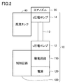
- FIG. 2 is a diagram schematically showing an example of the configuration of a pump unit 10
- FIG. 4 is a diagram showing a first specific example of the structure of the connecting pipe 13
- FIG. 4 is a diagram showing a second specific example of the structure of the connecting pipe 13
- FIG. 8 is a diagram showing a third specific example of the structure of the connecting pipe 13
- FIG. 10 is a diagram showing a fourth specific example of the structure of the connecting pipe 13
- FIG. 10 is a diagram showing a fifth specific example of the structure of the connecting pipe 13
- 4 is a diagram showing an example of a configuration for cooling the connecting pipe 13
- FIG. 4 is a diagram showing another example of a configuration for cooling the connecting pipe 13
- FIG. 1 is a schematic diagram for explaining the configuration of a nebulizer according to an embodiment
- FIG. 2 is a diagram schematically showing an example of the configuration of a pump
- the u piezoelectric pump 12 is located upstream of the fluid transport path in the pump unit 10, and the d piezoelectric pump 14 is located downstream of the fluid transport path.
- Each of the u piezoelectric pump 12 and the d piezoelectric pump 14 has a fluid inlet and outlet.
- the connecting pipe 13 connects the outlet of the u piezoelectric pump 12 and the inlet of the d piezoelectric pump 14 .
- the u piezoelectric pump 12 and the d piezoelectric pump 14 are connected in series on the transport path.
- the material of the connecting pipe 13 is silicon resin, metal (copper alloy, silver alloy, magnesium alloy, etc.), ceramics (aluminum nitride, silicon carbide, carbon steel, alumina, titanium alloy, etc.), glass (soda glass, etc.), polymeric materials (high density polyethylene, acrylonitrile-butadiene-styrene copolymers, etc.), or elastomers (ethylene-vinyl acetate copolymers, etc.), or combinations of these materials. .
- Inlet 14 i represents an opening provided in d piezoelectric pump 14 for introducing air from u piezoelectric pump 12 .
- the u piezoelectric pump 12 discharges air introduced from an inlet (not shown) through an outlet 12u.
- the d piezoelectric pump 14 discharges the air introduced from the inlet 14i through an outlet (not shown).
- the arrow A1 represents the direction of air flowing from the outlet 12u to the inlet 14i (for example, a straight line connecting the center point of the outlet 12u to the center point of the inlet 14i).
- Each fin 13X has a surface that intersects the arrow A1.
- the connecting pipe 13 passes through the intake pipe 90 .
- the arrow A1 represents the direction of air flowing from the outlet of the u piezoelectric pump 12 to the inlet of the d piezoelectric pump .
- the connecting pipe 13 is not communicated with the intake pipe 90 . That is, the pressure of the air flowing from the u piezoelectric pump 12 to the d piezoelectric pump 14 does not decrease due to leakage to the intake pipe 90 .
- the connecting pipe 13 can be cooled by the intake pipe 90 .
- Each of the chemical liquid tank 40A in FIG. 8 and the intake pipe 90 in FIG. 9 is an example of a cooling unit that cools the outer surface of the connecting pipe 13.
- the cooling unit may cool the connecting pipe 13 by contacting the outer surface of the connecting pipe 13 like the chemical tank 40A and the intake pipe 90, or may cool the outer surface of the connecting pipe 13 from a location spaced apart from the connecting pipe 13.
- Refrigerants medical liquids, other liquids, gases, solids including powders, etc.
- the cooling unit is realized for example by a fan or a solution injector.
Landscapes
- Engineering & Computer Science (AREA)
- Mechanical Engineering (AREA)
- General Engineering & Computer Science (AREA)
- Reciprocating Pumps (AREA)
Priority Applications (1)
| Application Number | Priority Date | Filing Date | Title |
|---|---|---|---|
| JP2023510794A JP7632597B2 (ja) | 2021-04-02 | 2022-03-10 | 流体制御装置 |
Applications Claiming Priority (2)
| Application Number | Priority Date | Filing Date | Title |
|---|---|---|---|
| JP2021063465 | 2021-04-02 | ||
| JP2021-063465 | 2021-04-02 |
Publications (1)
| Publication Number | Publication Date |
|---|---|
| WO2022209704A1 true WO2022209704A1 (ja) | 2022-10-06 |
Family
ID=83456047
Family Applications (1)
| Application Number | Title | Priority Date | Filing Date |
|---|---|---|---|
| PCT/JP2022/010565 Ceased WO2022209704A1 (ja) | 2021-04-02 | 2022-03-10 | 流体制御装置 |
Country Status (2)
| Country | Link |
|---|---|
| JP (1) | JP7632597B2 (https=) |
| WO (1) | WO2022209704A1 (https=) |
Citations (6)
| Publication number | Priority date | Publication date | Assignee | Title |
|---|---|---|---|---|
| JP2003075037A (ja) * | 2001-08-31 | 2003-03-12 | Hitachi Ltd | ピエゾポンプを用いた電子機器の冷却システム |
| JP2003286940A (ja) * | 2002-03-27 | 2003-10-10 | Minolta Co Ltd | 流体輸送システム |
| US20150292497A1 (en) * | 2014-04-10 | 2015-10-15 | Stichting Nationaal Lucht-En Ruimtevaart Laboratorium | Piezo pump and pressurized circuit provided therewith |
| WO2019198305A1 (ja) * | 2018-04-10 | 2019-10-17 | 株式会社村田製作所 | 流体制御装置 |
| WO2019202831A1 (ja) * | 2018-04-19 | 2019-10-24 | 株式会社村田製作所 | ポンプ装置 |
| WO2020217934A1 (ja) * | 2019-04-25 | 2020-10-29 | 株式会社村田製作所 | ポンプ装置 |
-
2022
- 2022-03-10 JP JP2023510794A patent/JP7632597B2/ja active Active
- 2022-03-10 WO PCT/JP2022/010565 patent/WO2022209704A1/ja not_active Ceased
Patent Citations (6)
| Publication number | Priority date | Publication date | Assignee | Title |
|---|---|---|---|---|
| JP2003075037A (ja) * | 2001-08-31 | 2003-03-12 | Hitachi Ltd | ピエゾポンプを用いた電子機器の冷却システム |
| JP2003286940A (ja) * | 2002-03-27 | 2003-10-10 | Minolta Co Ltd | 流体輸送システム |
| US20150292497A1 (en) * | 2014-04-10 | 2015-10-15 | Stichting Nationaal Lucht-En Ruimtevaart Laboratorium | Piezo pump and pressurized circuit provided therewith |
| WO2019198305A1 (ja) * | 2018-04-10 | 2019-10-17 | 株式会社村田製作所 | 流体制御装置 |
| WO2019202831A1 (ja) * | 2018-04-19 | 2019-10-24 | 株式会社村田製作所 | ポンプ装置 |
| WO2020217934A1 (ja) * | 2019-04-25 | 2020-10-29 | 株式会社村田製作所 | ポンプ装置 |
Also Published As
| Publication number | Publication date |
|---|---|
| JP7632597B2 (ja) | 2025-02-19 |
| JPWO2022209704A1 (https=) | 2022-10-06 |
Similar Documents
| Publication | Publication Date | Title |
|---|---|---|
| CN101277731B (zh) | 吸入器及吸入器用接口管 | |
| CN102858396B (zh) | 雾化器组件以及雾化器 | |
| CN102844067A (zh) | 雾化器套件及雾化器 | |
| JP2011512889A (ja) | 上流加湿器を持つ圧支持システム | |
| CN217162790U (zh) | 雾化组件及电子雾化器 | |
| TWM536948U (zh) | 微霧化裝置及微霧化器 | |
| WO2022209704A1 (ja) | 流体制御装置 | |
| CN102869404B (zh) | 雾化器组件以及雾化器 | |
| CN115363255A (zh) | 加热雾化组件、雾化装置及其电子雾化器 | |
| CN217161101U (zh) | 雾化组件及电子雾化器 | |
| CN112956750A (zh) | 雾化芯及设有其的雾化装置 | |
| CN110831650B (zh) | Cpap装置 | |
| WO2024174543A1 (zh) | 雾化器和电子雾化装置 | |
| CN209791807U (zh) | 雾化装置 | |
| WO2023241101A1 (zh) | 电子雾化装置 | |
| CN220308458U (zh) | 雾化器及雾化装置 | |
| CN223944704U (zh) | 一种喷吸鼻装置 | |
| CN116020020A (zh) | 一种用于治疗肺部疾病的雾化设备以及雾化系统 | |
| CN119701153B (zh) | 一种可加湿加温脉冲治疗仪 | |
| CN220936889U (zh) | 一种防压迫防内雾化口罩 | |
| CN222776966U (zh) | 雾化组件及设有其的电子雾化装置 | |
| CN115211588A (zh) | 电子雾化装置及其雾化器 | |
| CN219479229U (zh) | 电子雾化装置及雾化器 | |
| CN212756743U (zh) | 一种呼吸科用新型氧气雾化吸入器 | |
| WO2023241100A1 (zh) | 电子雾化装置 |
Legal Events
| Date | Code | Title | Description |
|---|---|---|---|
| 121 | Ep: the epo has been informed by wipo that ep was designated in this application |
Ref document number: 22779926 Country of ref document: EP Kind code of ref document: A1 |
|
| WWE | Wipo information: entry into national phase |
Ref document number: 2023510794 Country of ref document: JP |
|
| NENP | Non-entry into the national phase |
Ref country code: DE |
|
| 122 | Ep: pct application non-entry in european phase |
Ref document number: 22779926 Country of ref document: EP Kind code of ref document: A1 |