WO2022209703A1 - 測定アダプタ、測定システムおよび測定方法 - Google Patents
測定アダプタ、測定システムおよび測定方法 Download PDFInfo
- Publication number
- WO2022209703A1 WO2022209703A1 PCT/JP2022/010545 JP2022010545W WO2022209703A1 WO 2022209703 A1 WO2022209703 A1 WO 2022209703A1 JP 2022010545 W JP2022010545 W JP 2022010545W WO 2022209703 A1 WO2022209703 A1 WO 2022209703A1
- Authority
- WO
- WIPO (PCT)
- Prior art keywords
- measurement
- light
- sensor
- urine
- optical fiber
- Prior art date
Links
- 238000005259 measurement Methods 0.000 title claims abstract description 209
- 238000000691 measurement method Methods 0.000 title claims description 4
- 210000002700 urine Anatomy 0.000 claims abstract description 149
- 230000002485 urinary effect Effects 0.000 claims abstract description 23
- 230000003287 optical effect Effects 0.000 claims description 99
- 239000013307 optical fiber Substances 0.000 claims description 82
- OAICVXFJPJFONN-UHFFFAOYSA-N Phosphorus Chemical compound [P] OAICVXFJPJFONN-UHFFFAOYSA-N 0.000 claims description 75
- 230000005284 excitation Effects 0.000 claims description 42
- QVGXLLKOCUKJST-UHFFFAOYSA-N atomic oxygen Chemical compound [O] QVGXLLKOCUKJST-UHFFFAOYSA-N 0.000 claims description 35
- 229910052760 oxygen Inorganic materials 0.000 claims description 35
- 239000001301 oxygen Substances 0.000 claims description 35
- 229920001971 elastomer Polymers 0.000 claims description 19
- 239000000463 material Substances 0.000 claims description 19
- 238000004891 communication Methods 0.000 claims description 11
- CURLTUGMZLYLDI-UHFFFAOYSA-N Carbon dioxide Chemical compound O=C=O CURLTUGMZLYLDI-UHFFFAOYSA-N 0.000 claims description 10
- 239000000806 elastomer Substances 0.000 claims description 6
- 229910002092 carbon dioxide Inorganic materials 0.000 claims description 5
- 239000001569 carbon dioxide Substances 0.000 claims description 5
- 229910001414 potassium ion Inorganic materials 0.000 claims description 5
- 210000003734 kidney Anatomy 0.000 claims description 4
- 230000005855 radiation Effects 0.000 claims description 4
- 239000000126 substance Substances 0.000 claims description 4
- GPRLSGONYQIRFK-UHFFFAOYSA-N hydron Chemical compound [H+] GPRLSGONYQIRFK-UHFFFAOYSA-N 0.000 claims description 3
- 150000002500 ions Chemical class 0.000 claims description 3
- 238000000926 separation method Methods 0.000 claims description 3
- 229910001415 sodium ion Inorganic materials 0.000 claims description 3
- NPYPAHLBTDXSSS-UHFFFAOYSA-N Potassium ion Chemical compound [K+] NPYPAHLBTDXSSS-UHFFFAOYSA-N 0.000 claims 2
- FKNQFGJONOIPTF-UHFFFAOYSA-N Sodium cation Chemical compound [Na+] FKNQFGJONOIPTF-UHFFFAOYSA-N 0.000 claims 2
- 230000001678 irradiating effect Effects 0.000 claims 2
- 238000012986 modification Methods 0.000 description 45
- 230000004048 modification Effects 0.000 description 45
- 238000010586 diagram Methods 0.000 description 36
- 239000000835 fiber Substances 0.000 description 11
- 230000006870 function Effects 0.000 description 11
- 238000000034 method Methods 0.000 description 8
- 238000009529 body temperature measurement Methods 0.000 description 6
- 230000008569 process Effects 0.000 description 6
- 238000004458 analytical method Methods 0.000 description 5
- 230000008859 change Effects 0.000 description 5
- 230000027939 micturition Effects 0.000 description 5
- 239000011347 resin Substances 0.000 description 5
- 229920005989 resin Polymers 0.000 description 5
- 239000012790 adhesive layer Substances 0.000 description 4
- 239000010410 layer Substances 0.000 description 4
- 210000003708 urethra Anatomy 0.000 description 4
- 208000019206 urinary tract infection Diseases 0.000 description 4
- 208000009304 Acute Kidney Injury Diseases 0.000 description 3
- 208000033626 Renal failure acute Diseases 0.000 description 3
- 201000011040 acute kidney failure Diseases 0.000 description 3
- 238000012545 processing Methods 0.000 description 3
- 230000004044 response Effects 0.000 description 3
- PPBRXRYQALVLMV-UHFFFAOYSA-N Styrene Chemical compound C=CC1=CC=CC=C1 PPBRXRYQALVLMV-UHFFFAOYSA-N 0.000 description 2
- 239000000853 adhesive Substances 0.000 description 2
- 230000001070 adhesive effect Effects 0.000 description 2
- 239000000470 constituent Substances 0.000 description 2
- CVSVTCORWBXHQV-UHFFFAOYSA-N creatine Chemical compound NC(=[NH2+])N(C)CC([O-])=O CVSVTCORWBXHQV-UHFFFAOYSA-N 0.000 description 2
- 238000005401 electroluminescence Methods 0.000 description 2
- 230000005281 excited state Effects 0.000 description 2
- 230000010365 information processing Effects 0.000 description 2
- 239000000203 mixture Substances 0.000 description 2
- 238000005192 partition Methods 0.000 description 2
- 239000004033 plastic Substances 0.000 description 2
- 230000001902 propagating effect Effects 0.000 description 2
- UFHFLCQGNIYNRP-UHFFFAOYSA-N Hydrogen Chemical compound [H][H] UFHFLCQGNIYNRP-UHFFFAOYSA-N 0.000 description 1
- NIPNSKYNPDTRPC-UHFFFAOYSA-N N-[2-oxo-2-(2,4,6,7-tetrahydrotriazolo[4,5-c]pyridin-5-yl)ethyl]-2-[[3-(trifluoromethoxy)phenyl]methylamino]pyrimidine-5-carboxamide Chemical class O=C(CNC(=O)C=1C=NC(=NC=1)NCC1=CC(=CC=C1)OC(F)(F)F)N1CC2=C(CC1)NN=N2 NIPNSKYNPDTRPC-UHFFFAOYSA-N 0.000 description 1
- AFCARXCZXQIEQB-UHFFFAOYSA-N N-[3-oxo-3-(2,4,6,7-tetrahydrotriazolo[4,5-c]pyridin-5-yl)propyl]-2-[[3-(trifluoromethoxy)phenyl]methylamino]pyrimidine-5-carboxamide Chemical class O=C(CCNC(=O)C=1C=NC(=NC=1)NCC1=CC(=CC=C1)OC(F)(F)F)N1CC2=C(CC1)NN=N2 AFCARXCZXQIEQB-UHFFFAOYSA-N 0.000 description 1
- 229920006311 Urethane elastomer Polymers 0.000 description 1
- 230000003187 abdominal effect Effects 0.000 description 1
- 239000002390 adhesive tape Substances 0.000 description 1
- 150000001336 alkenes Chemical class 0.000 description 1
- 244000052616 bacterial pathogen Species 0.000 description 1
- 239000000090 biomarker Substances 0.000 description 1
- 210000001124 body fluid Anatomy 0.000 description 1
- 239000010839 body fluid Substances 0.000 description 1
- 239000006229 carbon black Substances 0.000 description 1
- 230000002490 cerebral effect Effects 0.000 description 1
- 239000002131 composite material Substances 0.000 description 1
- 238000007796 conventional method Methods 0.000 description 1
- 238000012937 correction Methods 0.000 description 1
- 229960003624 creatine Drugs 0.000 description 1
- 239000006046 creatine Substances 0.000 description 1
- 230000006866 deterioration Effects 0.000 description 1
- 238000009792 diffusion process Methods 0.000 description 1
- 239000003792 electrolyte Substances 0.000 description 1
- 239000012530 fluid Substances 0.000 description 1
- 230000005283 ground state Effects 0.000 description 1
- 238000010438 heat treatment Methods 0.000 description 1
- 229910052739 hydrogen Inorganic materials 0.000 description 1
- 239000001257 hydrogen Substances 0.000 description 1
- 238000001802 infusion Methods 0.000 description 1
- 230000009545 invasion Effects 0.000 description 1
- 239000007788 liquid Substances 0.000 description 1
- 239000004973 liquid crystal related substance Substances 0.000 description 1
- JRZJOMJEPLMPRA-UHFFFAOYSA-N olefin Natural products CCCCCCCC=C JRZJOMJEPLMPRA-UHFFFAOYSA-N 0.000 description 1
- 210000000056 organ Anatomy 0.000 description 1
- 230000000149 penetrating effect Effects 0.000 description 1
- 230000002093 peripheral effect Effects 0.000 description 1
- 229920000728 polyester Polymers 0.000 description 1
- 238000002360 preparation method Methods 0.000 description 1
- 230000035945 sensitivity Effects 0.000 description 1
- 210000002966 serum Anatomy 0.000 description 1
- 229920002379 silicone rubber Polymers 0.000 description 1
- 239000004945 silicone rubber Substances 0.000 description 1
- 230000003068 static effect Effects 0.000 description 1
Images


Classifications
-
- A—HUMAN NECESSITIES
- A61—MEDICAL OR VETERINARY SCIENCE; HYGIENE
- A61B—DIAGNOSIS; SURGERY; IDENTIFICATION
- A61B5/00—Measuring for diagnostic purposes; Identification of persons
- A61B5/20—Measuring for diagnostic purposes; Identification of persons for measuring urological functions restricted to the evaluation of the urinary system
- A61B5/207—Sensing devices adapted to collect urine
- A61B5/208—Sensing devices adapted to collect urine adapted to determine urine quantity, e.g. flow, volume
-
- A—HUMAN NECESSITIES
- A61—MEDICAL OR VETERINARY SCIENCE; HYGIENE
- A61B—DIAGNOSIS; SURGERY; IDENTIFICATION
- A61B5/00—Measuring for diagnostic purposes; Identification of persons
- A61B5/20—Measuring for diagnostic purposes; Identification of persons for measuring urological functions restricted to the evaluation of the urinary system
- A61B5/201—Assessing renal or kidney functions
-
- A—HUMAN NECESSITIES
- A61—MEDICAL OR VETERINARY SCIENCE; HYGIENE
- A61B—DIAGNOSIS; SURGERY; IDENTIFICATION
- A61B5/00—Measuring for diagnostic purposes; Identification of persons
- A61B5/68—Arrangements of detecting, measuring or recording means, e.g. sensors, in relation to patient
- A61B5/6846—Arrangements of detecting, measuring or recording means, e.g. sensors, in relation to patient specially adapted to be brought in contact with an internal body part, i.e. invasive
- A61B5/6847—Arrangements of detecting, measuring or recording means, e.g. sensors, in relation to patient specially adapted to be brought in contact with an internal body part, i.e. invasive mounted on an invasive device
- A61B5/6852—Catheters
- A61B5/6853—Catheters with a balloon
-
- A—HUMAN NECESSITIES
- A61—MEDICAL OR VETERINARY SCIENCE; HYGIENE
- A61F—FILTERS IMPLANTABLE INTO BLOOD VESSELS; PROSTHESES; DEVICES PROVIDING PATENCY TO, OR PREVENTING COLLAPSING OF, TUBULAR STRUCTURES OF THE BODY, e.g. STENTS; ORTHOPAEDIC, NURSING OR CONTRACEPTIVE DEVICES; FOMENTATION; TREATMENT OR PROTECTION OF EYES OR EARS; BANDAGES, DRESSINGS OR ABSORBENT PADS; FIRST-AID KITS
- A61F5/00—Orthopaedic methods or devices for non-surgical treatment of bones or joints; Nursing devices; Anti-rape devices
- A61F5/44—Devices worn by the patient for reception of urine, faeces, catamenial or other discharge; Portable urination aids; Colostomy devices
-
- A—HUMAN NECESSITIES
- A61—MEDICAL OR VETERINARY SCIENCE; HYGIENE
- A61M—DEVICES FOR INTRODUCING MEDIA INTO, OR ONTO, THE BODY; DEVICES FOR TRANSDUCING BODY MEDIA OR FOR TAKING MEDIA FROM THE BODY; DEVICES FOR PRODUCING OR ENDING SLEEP OR STUPOR
- A61M25/00—Catheters; Hollow probes
- A61M25/10—Balloon catheters
-
- G—PHYSICS
- G01—MEASURING; TESTING
- G01N—INVESTIGATING OR ANALYSING MATERIALS BY DETERMINING THEIR CHEMICAL OR PHYSICAL PROPERTIES
- G01N33/00—Investigating or analysing materials by specific methods not covered by groups G01N1/00 - G01N31/00
- G01N33/48—Biological material, e.g. blood, urine; Haemocytometers
- G01N33/483—Physical analysis of biological material
- G01N33/487—Physical analysis of biological material of liquid biological material
- G01N33/493—Physical analysis of biological material of liquid biological material urine
-
- A—HUMAN NECESSITIES
- A61—MEDICAL OR VETERINARY SCIENCE; HYGIENE
- A61M—DEVICES FOR INTRODUCING MEDIA INTO, OR ONTO, THE BODY; DEVICES FOR TRANSDUCING BODY MEDIA OR FOR TAKING MEDIA FROM THE BODY; DEVICES FOR PRODUCING OR ENDING SLEEP OR STUPOR
- A61M25/00—Catheters; Hollow probes
- A61M25/10—Balloon catheters
- A61M2025/1043—Balloon catheters with special features or adapted for special applications
- A61M2025/1068—Balloon catheters with special features or adapted for special applications having means for varying the length or diameter of the deployed balloon, this variations could be caused by excess pressure
Definitions
- the present invention relates to a measurement adapter, measurement system and measurement method.
- indwelling bladder catheters Various specifications of indwelling bladder catheters are used in medical settings. A doctor selects and uses an indwelling bladder catheter with appropriate specifications based on the patient's sex, age, physique, condition, and the like.
- a bladder indwelling catheter equipped with an oxygen sensor has been proposed. By measuring the partial pressure of oxygen in urine in real time, signs of acute kidney injury can be detected at an early stage (Patent Document 1).
- the purpose is to provide a measurement adapter etc. that can measure the state of urine in combination with an existing indwelling bladder catheter.
- the measurement adapter includes a catheter connection section connectable to an indwelling bladder catheter, a urine collection bag connection section connectable to a urine collection bag, a flow path arranged between the catheter connection section and the urine collection bag connection section, and and a plurality of sensor holders that hold sensors capable of detecting the state of urine flowing through the channel.
- a measurement adapter etc. that can measure the state of urine in combination with an existing indwelling bladder catheter.
- FIG. 3 is a cross-sectional view of the measurement adapter; FIG. 3 is a view in the direction of arrow III in FIG. 2; FIG. 4 is an explanatory diagram for explaining the structure of a measurement adapter; It is an explanatory view explaining composition of a measuring device.
- Fig. 10 is a perspective view of a fastener; 4 is a flowchart for explaining the flow of processing of a program; It is a screen example of modification 1-1.
- FIG. 11 is an explanatory diagram for explaining the configuration of Modified Example 1-2;
- FIG. 13 is an explanatory diagram for explaining the configuration of Modified Example 1-3; FIG.
- FIG. 4 is an explanatory diagram for explaining the configuration of an optical sensor unit
- FIG. 21 is an explanatory diagram for explaining the configuration of a measurement adapter according to Embodiment 7
- FIG. 20 is an explanatory diagram for explaining the configuration of an optical sensor unit of modification 7-1
- FIG. 20 is an explanatory diagram for explaining the configuration of an optical sensor unit of modification 7-2
- FIG. 20 is an explanatory diagram for explaining the configuration of an optical sensor unit of modification 7-3
- FIG. 20 is a cross-sectional view of a measurement adapter of modification 7-4
- FIG. 20 is a perspective view of a measurement adapter of modification 7-5
- FIG. 12 is a functional block diagram of a measurement system according to Embodiment 8;
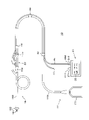
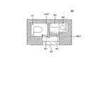
- FIG. 1 is an explanatory diagram for explaining the configuration of the measurement system 10.
- Measurement system 10 includes indwelling bladder catheter 15 , urine collection bag 17 , measurement adapter 20 and measurement device 30 .
- FIG. 1 is a diagram schematically showing each component of the measurement system 10. As shown in FIG.
- the bladder indwelling catheter 15 includes a shaft 153 having a side hole 151 and a balloon 152 at its tip, and a urination funnel 154 connected to one end of the shaft 153 .
- the urine collection bag 17 includes a bag 171 , a urine collection tube 172 and a connecting cylinder 173 .
- Bladder indwelling catheter 15 and urine collection bag 17 of the present embodiment have been conventionally used in the medical field. An outline of how to use the conventional indwelling bladder catheter 15 and urine collection bag 17 will be described.
- a user such as a doctor inserts the shaft 153 into the patient's urethra after connecting the urination funnel 154 and the connecting tube 173 .
- the user inflates the balloon 152 while the tip of the shaft 153 is inside the bladder.
- the balloon 152 shown in FIG. 1 is in an inflated state. By inflating the balloon 152, the shaft 153 will not come out of the urethra.
- the patient's urine passes through side hole 151 , shaft 153 and urine collection tube 172 and collects in bag 171 .
- the measurement adapter 20 is connected between the urination funnel 154 and the connecting tube 173 as shown in FIG.
- the patient's urine passes through side hole 151 , shaft 153 , measurement adapter 20 and urine collection tube 172 and collects in bag 171 .
- the measuring device 30 has a display section 35 , a first connector 371 and a second connector 372 .
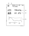
- the oxygen partial pressure (pO2) in the patient's urine and the temperature of the urine flowing through the measurement adapter 20 are displayed on the display unit 35 in real time.
- An optical fiber 41 and a thermocouple 45 are connected to the measurement adapter 20 .
- Thermocouple 45 is an example of a temperature sensor.
- the optical fiber 41 and thermocouple 45 are fixed to the urine collection tube 172 at three points by fasteners 49 .
- An optical fiber connector 411 provided at the end of the optical fiber 41 is connected to the first connector 371 .
- a thermocouple connector 452 provided at the end of the thermocouple 45 is connected to the second connector 372 .
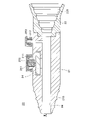
- FIG. 2 is a cross-sectional view of the measurement adapter 20.
- FIG. 3 is a view in the direction of arrow III in FIG. 2.
- the measurement adapter 20 includes a first tubular portion 21 and a second tubular portion 22 .
- the first tubular portion 21 and the second tubular portion 22 are connected in the longitudinal direction.
- a flow path 28 that is a through hole is provided along the longitudinal direction of the measurement adapter 20 .
- Urine that has entered the shaft 153 through the side hole 151 passes through the channel 28 and enters the urine collection tube 172 .
- the first tubular portion 21 is substantially cylindrical and has a first connecting portion 211 and a second connecting portion 212 protruding from the side surface.
- a male screw is provided on the outer periphery of each of the first connection portion 211 and the second connection portion 212 .
- a through-hole penetrating to the flow path 28 is provided in the first connection portion 211 and the second connection portion 212 .
- the first connection portion 211 and the second connection portion 212 are arranged side by side along the longitudinal direction of the channel 28 .
- a step that spreads outward is provided at the outer peripheral end of the through hole provided in the first connection portion 211 .
- a cylindrical holding rubber 252 is inserted inside the step.
- a large-diameter portion is provided on the side of the through-hole near the flow path 28 .
- a light-emitting body 24 is accommodated in the large-diameter portion. Light emitter 24 contacts urine flowing through channel 28 . The edge of the light emitter 24 is water-tightly adhered and fixed to the first cylindrical portion 21 to prevent urine from leaking through the hole provided in the first connecting portion 211 . The light emitter 24 will be described later.
- the first cylindrical portion 21 has a tapered catheter connection portion 218 on the outer surface of one end.
- the catheter connecting portion 218 is provided with streak-like projections for retaining.
- the first cylindrical portion 21 is hard, and is made of hard plastic, for example.
- the catheter connection part 218 has a size and a shape that can be connected to the urination funnel 154 of the indwelling bladder catheter 15, like the connection tube 173 of the urine collection bag 17 that has been used conventionally.
- the second tubular portion 22 has a tapered urine collection bag connection portion 228 on the inner surface of one end.
- the surface of the urine collection bag connecting portion 228 is provided with streak-like projections to prevent it from coming off.
- the second tubular portion 22 is made of rubber or elastomer and has rubber elasticity.
- the material forming the second tubular portion 22 is, for example, a styrene-based, olefin-based, or polyester-based elastomer.
- the urine collection bag connecting part 228 has a size and a shape that allows it to be connected to the connection cylinder 173 of the urine collection bag 17, like the urine funnel 154 of the indwelling bladder catheter 15 that has been used conventionally.
- first tubular portion 21 and the second tubular portion 22 are made of the same material as the material used for the connection between the existing indwelling bladder catheter 15 and the urine collection bag 17 .
- These existing instruments use silicone rubber elastomers, urethane rubber elastomers, and the like.
- the measurement adapter 20 can be attached between the conventionally used indwelling bladder catheter 15 and the urine collection bag 17.
- the user can use the indwelling bladder catheter 15 and the urine collection bag 17 appropriately selected according to the patient's condition, etc., in combination with the measurement adapter 20 .
- the first tubular portion 21 and the second tubular portion 22 are watertightly fixed, for example, by adhesion or screwing.
- the first tubular portion 21 and the second tubular portion 22 may be integrally formed of different materials.
- a first cap 251 having a through hole on the top surface is attached to the first connecting portion 211 .
- the inner surface of the first cap 251 is provided with a female thread that is screwed with the first connecting portion 211 .
- a second cap 262 having a through hole on the top surface is attached to the second connecting portion 212 .
- the inner surface of the second cap 262 is provided with a female thread that screws together with the second connecting portion 212 . 2 and 3, the screws of the first cap 251 and the second cap 262 are loosened.
- the luminous body 24 is, for example, a translucent resin plate into which a phosphor is kneaded.
- the light emitter 24 may be a translucent plate coated with phosphor.
- Fluorescence is an example of radiation emitted by light emitter 24 .
- Oxygen partial pressure and oxygen concentration in urine can be measured in real time by analyzing the characteristics of the fluorescence emitted by the phosphor.
- the outline of the measurement method using a fluorescent material will be explained.
- the phosphor When irradiated with excitation light, the phosphor enters a high-energy excited state. Fluorescence is emitted from the phosphor in the excited state, and the phosphor returns to the ground state.
- the properties of the fluorescence such as the intensity, phase angle and decay time of the emitted fluorescence, change based on the concentration of quencher with which the fluorophore contacts and the environment such as ambient temperature and pressure. Therefore, by analyzing the characteristics of the radiated light, it is possible to measure the concentration of the quencher, the ambient temperature, and the like.
- the quencher is, for example, oxygen.
- a diffusion permeation film placed on the surface of the emitter 24 can select the quencher, ie the component to be measured, that contacts the phosphor.
- a fluorophore that reacts with a specific quencher may be used.
- the emitted light emitted by the phosphor also includes phosphorescence. Measurements may be made by analyzing the properties of phosphorescence.
- the luminous body 24 may have a fluorescent substance only in the portion facing the channel 28 .
- the luminous body 24 may have a projection on the portion facing the flow path 28 . Having the protrusion ensures that the light emitter 24 comes into contact with the urine flowing in the channel 28 .
- the phosphor may emit fluorescence in response to carbon dioxide in urine. By analyzing the fluorescence characteristics, it is possible to measure the carbon dioxide partial pressure and carbon dioxide concentration in urine in real time. Phosphors may vary in the properties of the fluorescence they emit depending on the pH of urine. By analyzing the properties of fluorescence, it is possible to measure the urinary hydrogen ion exponent, or pH (potential of Hydrogen), in real time.
- the phosphor may react with ions such as potassium ions or sodium ions in urine to emit fluorescence.
- ions such as potassium ions or sodium ions in urine
- concentration of electrolytes in urine can be measured in real time.
- a fluorescent substance that reacts with any component in urine and emits fluorescence may be used.
- the fluorescent properties of phosphors change depending on the temperature.
- urine temperature can be measured in real time.
- the phosphor may change its luminous state depending on the flow rate of urine that comes in contact with it.
- the urine flow rate can be measured in real time.
- FIG. 4 is an explanatory diagram explaining the structure of the measurement adapter 20.
- the tip of the optical fiber 41 is inserted into the through hole provided in the first connecting portion 211
- the tip of the thermocouple 45 is inserted into the through hole provided in the second connecting portion 212 .
- the tip of the optical fiber 41 is butted against the light emitter 24 .
- the first cap 251 is tightened, and the holding rubber 252 is compressed vertically in FIG.
- the compressed holding rubber 252 swells in the radial direction, that is, in the horizontal direction in FIG. 4, and presses and fixes the side surface of the optical fiber 41 .
- the holding rubber 252 returns to its original shape, and the optical fiber 41 can be removed from the measurement adapter 20 . That is, the optical fiber 41 is attachable/detachable to/from the measurement adapter 20 .
- thermocouple 45 A temperature measuring junction 451 provided at the tip of the thermocouple 45 is arranged inside the flow path 28 .
- the second cap 262 is tightened, and the thermocouple 45 is liquid-tightly held by liquid-tight rubber (not shown).
- the through-hole provided in the first connection portion 211 and the through-hole provided in the second connection portion 212 are both examples of the sensor holding portion of the present embodiment.
- the large-diameter portion accommodating the light emitter 24 is an example of the light emitter holding portion of the present embodiment.
- the outer stepped portion and the holding rubber 252 arranged in the stepped portion are examples of the optical fiber holding portion of the present embodiment.
- the through hole provided in the second connection portion 212 is an example of the temperature sensor holding portion.
- the first cylindrical portion 21 is composed of two members, for example, a member having a large-diameter portion that accommodates the light emitter 24 open to the surface and a stepped cylindrical member that includes the first connecting portion 211 .
- the boundary between the two members is indicated by a chain double-dashed line labeled B in FIG.
- the first cylindrical portion 21 can be manufactured by bonding and fixing a stepped cylindrical member.
- the fixing structures of the optical fiber 41 and the thermocouple 45 described using FIGS. 2 to 3 are examples. Any structure that can prevent misalignment of optical fiber 41 and thermocouple 45 during use of measurement adapter 20 can be employed. For example, a structure may be employed in which the unevenness formed on the surfaces of the optical fiber 41 and the thermocouple 45 and the unevenness formed on the measurement adapter 20 are fitted.
- thermocouple 45 and the measurement adapter 20 may be fixed using an adhesive. If the thermocouple 45 and the measurement adapter 20 do not need to be attached and detached, they may be fixed in a liquid-tight state using an adhesive. A measurement adapter 20 that is easy to set can be provided.
- the through-hole provided in the first connecting portion 211 and the through-hole provided in the second connecting portion 212 may be inclined with respect to the channel 28 .
- the optical fiber 41 and thermocouple 45 are obliquely attached to the measurement adapter 20 .
- the optical fiber 41 and the thermocouple 45 are easily made to run along the urine collection tube 172 . Therefore, it is possible to provide the measurement adapter 20 in which the optical fiber 41 and the thermocouple 45 are less likely to come off.
- a check valve for preventing backflow of urine in the channel 28 may be provided at the portion indicated by A in FIG.
- FIG. 5 is an explanatory diagram illustrating the configuration of the measuring device 30.
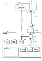
- the measurement device 30 includes the control unit 31, the main storage device 32, the auxiliary storage device 33, the communication unit 34, the input unit 36, the temperature measuring device 39, the light source. 51, an optical analyzer 52, an optical waveguide 55, a beam splitter 56 and a bus.
- the control unit 31 is an arithmetic control device that executes the program of this embodiment. One or a plurality of CPUs (Central Processing Units), GPUs (Graphics Processing Units), multi-core CPUs, or the like is used for the control unit 31 .
- the control unit 31 is connected to each hardware unit constituting the measuring device 30 via a bus.
- the main storage device 32 is a storage device such as SRAM (Static Random Access Memory), DRAM (Dynamic Random Access Memory), flash memory, or the like.
- the main storage device 32 temporarily stores information necessary during the process performed by the control unit 31 and the program being executed by the control unit 31 .
- the auxiliary storage device 33 is a storage device such as SRAM, flash memory, hard disk, or magnetic tape.
- the auxiliary storage device 33 stores programs to be executed by the control unit 31 and various data necessary for executing the programs.
- the communication unit 34 is an interface that performs communication between the measuring device 30 and a network or other equipment.
- the display unit 35 is, for example, a liquid crystal display panel or an organic EL (electro-luminescence) panel.
- the display unit 35 is attached to the housing of the measuring device 30 as shown in FIG.
- the display unit 35 may be a separate display device from the measuring device 30 .
- a screen of another device such as a biological information monitor may also serve as the display unit 35 .
- the input unit 36 is a button or the like provided on the housing of the measuring device 30 .
- the display unit 35 and the input unit 36 may be an integrated panel.
- the first connector 371 is an optical connector to which the optical fiber 41 is connected.
- the second connector 372 is an electrical connector to which the thermocouple 45 is connected.
- the measuring device 30 may comprise multiple first connectors 371 .
- the light source 51 is, for example, an LED (light emitting diode) or a laser diode.
- the light source 51 irradiates the light emitter 24 with excitation light to excite the phosphor contained in the light emitter 24 .
- the excitation light is an example of irradiation light emitted from the light source 51 to the light emitter 24 .
- the light emitted by the light source 51 hardly contains the wavelength of fluorescence emitted by the phosphor.
- the optical analyzer 52 analyzes the received light after converting it into an electrical signal using, for example, a photodiode.
- a light guide path 55 connects between the light source 51 and the beam splitter 56, between the optical analyzer 52 and the beam splitter 56, and between the beam splitter 56 and the first connector 371, respectively.
- the temperature measuring device 39 is connected to the second connector 372.
- the temperature measuring device 39 measures the temperature near the temperature measuring junction 451 based on the thermoelectromotive force generated in the thermocouple 45 connected to the second connector 372, and outputs it to the bus. Since temperature measurement by the thermocouple 45 has been conventionally performed, detailed description thereof will be omitted. Instead of the thermocouple 45, any sensor capable of measuring temperature, such as a thermistor, a resistance temperature detector, or a phosphor, may be connected to the temperature measuring device 39.
- the wavelength range of the excitation light with which the light-emitting body 24 is irradiated can be precisely selected. Since noise due to wavelengths other than the excitation light does not occur, the measurement device 30 with high measurement accuracy can be provided.
- An optical lens may be arranged in the middle of the light guide path 55 or at the end of the light guide path 55 .
- the measurement device 30 may have a second light source that supplies reference light to the optical analyzer 52 in addition to the light source 51 that emits excitation light. It is possible to provide the measurement device 30 that performs analysis using reference light.
- the reference light emitted from the second light source directly enters the light analyzer 52 .
- the second light source and the optical analyzer 52 are connected, for example, by a dedicated light guide path. Between the second light source and the light analyzer 52 may be a cavity configured such that the light emitted from the second light source is incident on the light analyzer 52 .
- the measuring device 30 may include a plurality of second connectors 372 and temperature measuring devices 39.
- the measuring device 30 may include any measuring instrument such as a flow meter or a pressure gauge, and a connector for connecting a sensor corresponding to the measuring instrument.
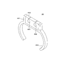
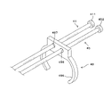
- FIG. 6 is a perspective view of the fastener 49.
- the fastener 49 comprises a first part 491 and a second part 492 .
- the first component 491 has a substantially C-shaped urine collection tube holding portion 496 .
- the second part 492 is attached to the outside of the urine collection tube holder 496 .
- the second part 492 has an optical fiber holder 497 and a thermocouple holder 498 located at the bottom of the slit, respectively.
- the urine collection tube holding portion 496 has a dimension that allows it to be fitted around the outer circumference of the urine collection tube 172 .
- the optical fiber holding portion 497 has a dimension capable of holding the optical fiber 41 pushed through the slit.
- the thermocouple holding portion 498 has a dimension capable of holding the thermocouple 45 pushed through the slit.
- the first material forming the first part 491 is desirably a relatively hard and flexible material such as hard plastic.
- the second material forming the second part 492 is preferably an elastomer such as rubber.
- the first material may be a softer material than the second material.
- the first part 491 and the second part 492 may be integrally formed from the same material.
- the optical fiber 41 and thermocouple 45 are fixed to the urine collection tube 172 at three locations with fasteners 49.
- Optical fiber 41 and thermocouple 45 may be fixed using, for example, medical tape instead of fastener 49 .
- Optical fiber 41 and thermocouple 45 may be fixed to any location, such as an IV stand or bed rail.
- FIG. 1 an outline of how to use the measurement system 10 will be described.
- the user connects the indwelling bladder catheter 15 , the measurement adapter 20 and the urine collection bag 17 .
- a user connects the optical fiber 41 and the thermocouple 45 to the measurement adapter 20 and the measurement device 30, respectively.
- the user fixes the optical fiber 41 and the thermocouple 45 to the urine collection tube 172 using the fastener 49 .
- the user inserts the shaft 153 into the patient's urethra.
- the user inflates the balloon 152 while the tip of the shaft 153 is inside the bladder.
- the bladder indwelling catheter 15 is left in the patient.
- the patient's urine passes through side hole 151 , shaft 153 , channel 28 and urine collection tube 172 and collects in bag 171 .
- the user operates the measuring device 30 to operate the light source 51 .
- the excitation light emitted from the light source 51 is applied to the light emitter 24 via the light guide path 55 , the beam splitter 56 and the optical fiber 41 .
- fluorescence corresponding to oxygen in the urine is emitted. That is, the light emitter 24 functions as a sensor capable of detecting oxygen partial pressure and oxygen concentration in urine.
- a beam splitter 56 causes the fluorescent light to enter an optical waveguide 55 leading to an optical analyzer 52 .
- the optical analyzer 52 analyzes the characteristics of the incident fluorescence and outputs the oxygen partial pressure or oxygen concentration in urine to the bus in real time.
- the control unit 31 displays the temperature output from the temperature measuring device 39 and the partial pressure of oxygen in urine output from the optical analyzer 52 on the display unit 35 .
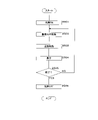
- FIG. 7 is a flowchart explaining the flow of program processing.
- the control unit 31 starts the program of FIG. 7 when the user gives an instruction to operate the light source 51 .
- the control unit 31 turns on the light source 51 (step S501).
- the excitation light is applied to the light emitter 24 via the beam splitter 56 and the optical fiber 41 .
- Fluorescence emitted from the phosphor of the light emitter 24 enters the optical analyzer 52 via the optical fiber 41 and the beam splitter 56 .
- the optical analyzer 52 outputs urinary oxygen partial pressure data based on the fluorescence.
- the controller 31 acquires urinary oxygen partial pressure data from the optical analyzer 52 (step S502).
- the temperature measuring device 39 outputs temperature data based on the thermoelectromotive force of the thermocouple 45.
- the control unit 31 acquires temperature data from the temperature measuring device 39 (step S503). Through steps S502 and S503, the control unit 31 implements the function of a data acquisition unit that acquires data from the sensors held in the sensor holding unit.
- the control unit 31 displays the urinary oxygen partial pressure and the temperature on the display unit 35 as illustrated in FIG. 1 (step S504).
- the control unit 31 determines whether or not to end the process (step S505). For example, when the control unit 31 receives an operation to turn off the light source 51, when the optical fiber 41 is removed from the first connector 371, or when the thermocouple 45 is removed from the second connector 372, it determines to end the process. do.
- step S505 When determining to end the process (YES in step S505), the control unit 31 turns off the light source 51 (step S506). The control unit 31 terminates the process. If it is determined not to end the process (NO in step S505), the control unit 31 returns to step S502.
- the measurement adapter 20 capable of measuring oxygen partial pressure in urine in real time.
- the user can use the indwelling bladder catheter 15 selected based on the patient's condition, past experience, expertise, etc., in combination with the measurement adapter 20 of the present embodiment.
- the control unit 31 may notify the user, for example, when the partial pressure of oxygen in urine becomes equal to or less than the threshold. For example, the control unit 31 notifies the user through display on the display unit 35 or audio output from the measuring device 30 .
- the control unit 31 may transmit the notification to a nurse station or the like via a network such as HIS (Hospital Information System) or EMR (Electronic Medical Record).
- HIS Hospital Information System
- EMR Electronic Medical Record
- the control unit 31 may, for example, calculate an index representing the state of urinary organs such as the kidneys based on the partial pressure of oxygen in urine and the temperature, and display the index on the display unit 35 .
- the index representing the state of the urinary system may be calculated by combining information acquired from other equipment such as a biological information monitor and the oxygen partial pressure and temperature in urine.
- the index is not limited to the urinary system, and may be an index representing the patient's general condition. In this case, the control unit 31 implements the function of an index calculation unit that calculates an index representing the state of the urinary system.
- the optical analyzer 52 may output data indicating characteristics of fluorescence such as the intensity, phase angle and decay time of the received fluorescence to the bus. In such a case, the control unit 31 calculates the urinary oxygen partial pressure, the urinary oxygen concentration, or the like.
- the temperature measuring device 39 may output data indicating the voltage value of the thermoelectromotive force to the bus. In doing so, the controller 31 calculates the temperature based on the voltage value.
- the light analysis block which is composed of the light source 51, the light analyzer 52, the light guide path 55, the beam splitter 56 and the first connector 371, may be separate from the measuring device 30.
- a temperature measurement block composed of the temperature measurement device 39 and the second connector 372 may be separate from the measurement device 30 .
- a general-purpose information processing device such as a personal computer, tablet, or smartphone, the light analysis block, and the temperature measurement block are combined to obtain the measurement device of the present embodiment. 30 may be configured.
- the optical analysis block and temperature measurement block and the information processing device are connected by wire or wirelessly.
- the display of the display unit 35 shown in FIG. 1 is an example.
- the measuring device 30 displays the concentration of potassium ions in urine on the display unit 35 in real time.
- the measurement adapter 20 is preferably a single-use product that is supplied to the user in a sterile condition. By doing so, the risk of developing urinary tract infections can be reduced.
- the measurement adapter 20 may be attached to any tube used for continuous drainage of body fluids from a patient, such as a chest drainage tube, an abdominal drainage tube, or a cerebral drainage tube. good. Measurement adapter 20 may be attached to any tube used to deliver fluids into a patient's body, such as an infusion tube or feeding tube.
- Modification 1-1 This modification relates to a measurement system 10 that displays time-series data on the display unit 35.
- FIG. Descriptions of parts common to the first embodiment are omitted.
- FIG. 8 is a screen example of modification 1-1.
- a relatively large display section 35 is used.
- An index field 67, a date and time field 61, an oxygen partial pressure field 62, a temperature field 63 and a graph field 68 are displayed on the screen.
- the index column 67 displays indices representing the state of the kidney. The user can easily grasp the patient's kidney condition by combining the alphabet and the symbol "+" or "-".
- the date and time column 61 displays the date, day of the week and time.
- the oxygen partial pressure field 62 displays the oxygen partial pressure in urine. Temperature is displayed in the temperature column 63 .
- time-series data of oxygen partial pressure in urine and temperature are displayed by line graphs.
- the dashed line indicates time-series data of oxygen partial pressure in urine
- the solid line indicates time-series data of temperature.
- a dashed line displayed under the word "pO2" and a solid line displayed under the word "temperature” in the oxygen partial pressure column 62 function as a so-called legend column. The user can easily grasp which graph means what.
- the line graph shown in the graph column 68 is an example of the graph format. Any type of graph that is convenient for a user to use in a clinical setting can be used in graph field 68 . For example, when the value per unit time is emphasized, a bar graph is used for displaying the graph field 68 . The user may be able to specify the format of the graph as appropriate.
- Time-series data may be displayed in tabular format instead of graphical format.
- the control unit 31 may appropriately receive a setting change of the items and layout to be displayed on the display unit 35 by the user. The user can use the measurement system 10 with settings that are easy to use depending on the situation.
- Modification 1-2 This modification relates to the measurement system 10 in which the optical fiber 41 is divided into a fiber for irradiation light and a fiber for light reception. Descriptions of parts common to the first embodiment are omitted.
- FIG. 9 is an explanatory diagram for explaining the configuration of modification 1-2.
- the optical fiber 41 is divided into two bundles at the end, one bundle is connected to the fluorescence connector 413 and the other bundle is connected to the irradiation optical connector 414 .
- the measuring device 30 includes a third connector 373 and a fourth connector 374 instead of the first connector 371.
- the third connector 373 is connected to the optical analyzer 52 via the light guide path 55 .
- the fourth connector 374 is connected to the light source 51 via the light guide path 55 .
- the excitation light emitted from the light source 51 irradiates the light emitter 24 via the light guide path 55 , the fourth connector 374 and the irradiation light connector 414 .
- Fluorescence emitted from the light emitter 24 enters the optical analyzer 52 via the optical fiber 41 , fluorescence connector 413 , first connector 371 and light guide 55 .
- a fiber for irradiation light and a fiber for light reception may be coupled to one common fiber commonly used for irradiation light (excitation light) and light reception (fluorescence).
- the fiber for irradiation light and the fiber for light reception may be separate, and both may be bundled on the side where the measurement adapter 20 is attached.
- a fiber with specifications suitable for propagation of excitation light may be used as the fiber for irradiation light, and a fiber with specifications suitable for propagation of fluorescence may be used as the fiber for light reception.
- Modification 1-3 This modification relates to a fastener 49 through which an optical fiber 41 and a thermocouple 45 are inserted. Descriptions of parts common to the first embodiment are omitted.
- FIG. 10 is an explanatory diagram for explaining the configuration of modification 1-3.
- the fastener 49 has a substantially C-shaped urine collection tube holding portion 496 and a circular hole-shaped optical fiber holding portion 497 and thermocouple holding portion 498 .
- the thermocouple 45 is inserted through the thermocouple holder 498 . Although illustration is omitted, the optical fiber 41 and the thermocouple 45 are inserted through a plurality of fasteners 49 .
- the measurement system 10 is provided that can smoothly perform from the connection of the optical fiber 41 and the thermocouple 45 to the measurement adapter 20 and the measurement device 30 to the fixing of the optical fiber 41 and the thermocouple 45 with the fastener 49. can.
- Modification 1-4 This modification relates to a measurement adapter 20 having a cover 29.
- FIG. Descriptions of parts common to the first embodiment are omitted.
- FIG. 11 is an explanatory diagram for explaining the structure of the measurement adapter 20 of modification 1-4.
- a cover 29 is attached to the side surface of the measurement adapter 20 .
- the cover 29 has a tubular shape that is thicker than the measurement adapter 20, and is attached to the side surface of the measurement adapter 20 with appropriate tacks.
- An attachment portion 291 is attached to the end of the cover 29 .
- the attachment portion 291 is a string that can pull the cover 29 tight.
- a first cap 251 and a second cap 262 protrude from holes provided in the cover 29 . As shown in FIG. 11, the measurement adapter 20 is supplied to the user with the cover 29 folded multiple times.
- FIG. 12 is an explanatory diagram for explaining how to use the measurement system 10 of modification 1-4.
- the user connects the indwelling bladder catheter 15 , the measurement adapter 20 and the urine collection bag 17 .
- the user connects the optical fiber 41 and the thermocouple 45 to the measuring device 30, respectively.
- the user fixes the optical fiber 41 and the thermocouple 45 to the urine collection tube 172 using the fastener 49 .
- FIG. 12 shows the stage at which the above steps have been completed. Note that the cover 29 may be fixed by medical tape or the like instead of the mounting portion 291 .
- the attachment part 291 is not limited to a string capable of pulling the cover 29.
- the attachment portion 291 may be rubber or the like attached to the end of the cover 29 .
- the attachment portion 291 may be an adhesive tape attached to the inside of the cover 29 .
- the attachment portion 291 may be made of a material that shrinks into a tubular shape by simple heating.
- the user connects the optical fiber 41 and the thermocouple 45 to the measurement adapter 20. With the above, the preparation for use of the measurement system 10 is completed.
- the measurement adapter 20 may have a shape in which the first cap 251 and the holding rubber 252 are covered with the cover 29 together with the optical fiber 41 and thermocouple 45 . Furthermore, the risk of developing urinary tract infections can be reduced.
- FIG. 13 is an explanatory diagram for explaining the structure of the measurement adapter 20 according to the second embodiment.
- the through hole provided in the first connection portion 211 is not provided with a large-diameter portion for accommodating the light emitter 24 .
- the measurement adapter 20 does not have the second connection section 212 .
- the measurement adapter 20 incorporates a flow rate measurement section 27 .
- the flow rate measurement unit 27 functions as a flow rate sensor that measures the flow rate of urine flowing through the channel 28 .
- a portion of the measurement adapter 20 that holds the flow rate measuring section 27 functions as a flow rate sensor holding section that holds the flow rate sensor.
- the flow rate measurement unit 27 is, for example, an optical flow meter that measures the flow rate by the laser Doppler method using an optical flow sensor, or an ultrasonic flow meter that measures the flow rate by the ultrasonic Doppler method using an ultrasonic flow sensor. be.
- the flow measurement unit 27 may be a thermal flow sensor.
- the flow rate measurement unit 27 may measure the urine flow rate by obtaining changes over time in the weight of the catheterized urine.
- the flow rate measurement unit 27 has a wireless communication function.
- FIG. 14 is an explanatory diagram for explaining the configuration of the measurement system 10 according to the second embodiment.
- FIG. 14 is a diagram schematically showing each component of the measurement system 10. As shown in FIG.
- the measurement device 30 includes a control unit 31, a main storage device 32, an auxiliary storage device 33, a communication unit 34, an input unit 36, a light source 51, an optical analyzer 52, an optical waveguide 55, a beam splitter 56, a first connector 371 and a bus. Prepare.
- the measuring device 30 receives the flow rate from the flow rate measuring section 27 via wireless communication.
- the measuring device 30 may receive the flow rate from the flow rate measuring section 27 via a wired connection.
- an ultrasonic Doppler signal may be transmitted from the flow rate measurement unit 27 and the control unit 31 may analyze the signal to calculate the flow rate.
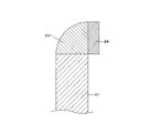
- FIG. 15 is an enlarged view of the XV portion in FIG.
- a light emitter 24 is adhered to the end surface of the optical fiber 41 via an adhesive layer 241 .
- the light-emitting body 24 is, for example, a plate made of translucent resin into which phosphor is kneaded.
- the light emitter 24 may be a translucent plate coated with phosphor.
- a light shielding layer may be arranged on the side of the light emitter 24 that comes into contact with the liquid, which blocks ambient light but allows a light quencher such as oxygen to pass therethrough. By providing the light shielding layer, deterioration of the phosphor due to ambient light can be prevented.
- the light shielding layer is made of carbon black, for example.
- FIG. 16 is a cross-sectional view for explaining the configuration of the optical fiber tip portion of modification 2-1.
- FIG. 16 shows an enlarged view of the same part as in FIG. In this modified example, the end of the optical fiber 41 is covered with the light emitter 24 .
- the optical fiber 41 of this modification can be manufactured by immersing the tip of the optical fiber 41 in an uncured transparent resin in which a phosphor is kneaded, pulling it out, and then curing it.
- a mold may be used to mold the transparent resin into which the phosphor is kneaded at the tip of the optical fiber 41 .
- FIG. 17 is a cross-sectional view for explaining the configuration of the optical fiber tip portion of modification 2-2.
- FIG. 17 shows an enlarged view of the same part as in FIG. In this modification, a plate-like light emitter 24 is fixed substantially perpendicular to the end of the optical fiber 41 .
- the end of the optical fiber 41 and the light emitter 24 are fixed with an adhesive layer 241 using, for example, translucent resin.
- an adhesive layer 241 a translucent part having a predetermined shape may be adhesively fixed between the optical fiber 41 and the light emitter 24 .
- This embodiment relates to a measurement device 30 that includes a filter 57 that separates excitation light and fluorescence. Descriptions of parts common to the first embodiment are omitted.
- FIG. 18 is an explanatory diagram for explaining the configuration of the measuring device 30 of the third embodiment.
- a filter 57 is arranged between the beam splitter 56 and the first connector 371 via the light guide path 55 .
- the control unit 31 can adjust the wavelength range of light transmitted by the filter 57 .
- the light source 51 of the present embodiment emits broadband light that includes fluorescence wavelengths in addition to excitation light wavelengths.
- Light source 51 is, for example, a white LED.
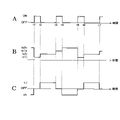
- FIG. 19 is a time chart explaining the operation of the measuring device 30 of Embodiment 3.
- FIG. 19A shows ON and OFF timings of the light source 51 .
- FIG. 19B shows the timing of the operation of filter 57.
- FIG. b1 indicates that the filter 57 transmits the excitation light.
- b2 indicates that the filter 57 transmits fluorescence.
- FIG. 19C shows the timing at which the optical analyzer 52 operates. ON indicates the operation of analyzing the properties of fluorescence. OFF indicates an operation in which fluorescence characteristics are not analyzed.
- the horizontal axes in FIGS. 19A to 19C all indicate time.
- the light source 51 is in the ON state during the period from time t1 to time t2. During this period, the filter 57 transmits the excitation light. Optical analyzer 52 does not operate. The excitation light irradiates the light emitter 24 . When the light-emitting body 24 is in contact with urine, fluorescence corresponding to the state of urine is emitted.
- the light source 51 is turned off during the period from time t2 to t3. During this period, filter 57 is transparent to fluorescence.
- the optical analyzer 52 analyzes the fluorescence characteristics and outputs the partial pressure of oxygen in the urine to the bus. After time t3, the same operation is repeated.
- the measurement system 10 that can perform accurate measurements even when the light emitted by the light source 51 contains the wavelength of fluorescence.
- the light-emitting body 24 of this embodiment includes two types of phosphors.
- the two types of phosphors are referred to as phosphor J and phosphor K in the following description.
- the wavelengths of the fluorescence emitted by the phosphor J and the phosphor K are sufficiently separated.
- FIG. 20 is a time chart explaining the operation of the measuring device 30 of the fourth embodiment.
- FIG. 20A shows ON and OFF timings of the light source 51 .
- 20B shows the timing of the operation of filter 57.
- FIG. b1j indicates that the filter 57 allows the excitation light of the phosphor J to pass therethrough.
- b2j indicates that the filter 57 allows the fluorescence emitted by the phosphor J to pass through.
- b1k indicates that the filter 57 allows the excitation light of the phosphor K to pass therethrough.
- b2k indicates that the filter 57 allows the fluorescence emitted by the phosphor K to pass through.
- FIG. 20C shows the timing at which the optical analyzer 52 operates.
- cj indicates the operation of analyzing the characteristics of the fluorescence emitted by the phosphor J; ck indicates the operation of analyzing the properties of the fluorescence emitted by the phosphor K; OFF indicates an operation in which fluorescence characteristics are not analyzed.
- the horizontal axes in FIGS. 20A to 20C all indicate time.
- the light source 51 is in the ON state during the period from time t1 to time t2. During this period, the filter 57 allows the excitation light of the phosphor J to pass therethrough. Optical analyzer 52 does not operate. The excitation light irradiates the light emitter 24 . When the light emitter 24 is in contact with urine, the phosphor J emits fluorescence corresponding to the state of urine.
- the light source 51 is turned off during the period from time t2 to time t3. During this period, the filter 57 allows the fluorescence emitted by the phosphor J to pass therethrough.
- the light analyzer 52 analyzes the properties of the fluorescence and outputs items related to the phosphor J on the bus.
- the light source 51 is in the ON state during the period from time t3 to time t4. During this period, the filter 57 allows the excitation light of the phosphor K to pass therethrough. Optical analyzer 52 does not operate. The excitation light irradiates the light emitter 24 . When the light emitter 24 is in contact with urine, the phosphor K emits fluorescence corresponding to the state of urine.
- the light source 51 is turned off during the period from time t4 to time t5. During this period, the filter 57 allows the fluorescence emitted by the phosphor K to pass therethrough.
- the light analyzer 52 analyzes the properties of the fluorescence and outputs items related to the phosphor K on the bus. After time t6, the same operation is repeated.
- the measurement system 10 that can measure a plurality of items using one light source 51.
- the light emitter 24 may have three or more types of phosphors.
- the filter 57 sequentially transmits excitation light and fluorescence of each phosphor.
- FIG. 21 is an explanatory diagram illustrating the configuration of the measuring device 30 according to the fifth embodiment.
- filter 57 is placed between beam splitter 56 and optical analyzer 52 .
- FIG. 22 is a time chart explaining the operation of the measuring device 30 of Embodiment 5.
- FIG. FIG. 22A shows the timing at which the light source 51 operates. aj indicates that the light source 51 emits excitation light for the phosphor J; ak indicates that the light source 51 emits excitation light for the phosphor K;
- FIG. 22B shows the timing of the operation of the filter 57.
- FIG. ALL indicates that filter 57 transmits all light.
- bj indicates that the filter 57 allows the fluorescence emitted by the phosphor J to pass through.
- bk indicates that the filter 57 allows the fluorescence emitted by the phosphor K to pass through.
- FIG. 22C shows the timing at which the optical analyzer 52 operates.
- cj indicates the operation of analyzing the characteristics of the fluorescence emitted by the phosphor J; ck indicates the operation of analyzing the properties of the fluorescence emitted by the phosphor K; OFF indicates an operation in which fluorescence characteristics are not analyzed.
- the horizontal axes in FIGS. 22A to 22C all indicate time.
- the light source 51 emits excitation light that excites the phosphor J during the period from time t1 to time t2. During this period, filter 57 transmits all light. Optical analyzer 52 does not operate. The excitation light irradiates the light emitter 24 . When the light emitter 24 is in contact with urine, the phosphor J emits light according to the state of the urine.
- the light source 51 is turned off during the period from time t2 to time t3. During this period, the filter 57 allows the fluorescence emitted by the phosphor J to pass therethrough.
- Optical analyzer 52 analyzes the properties of the fluorescence emitted by phosphor J and outputs the results on a bus.
- the light source 51 emits excitation light that excites the phosphor K during the period from time t3 to time t4. During this period, filter 57 transmits all light. Optical analyzer 52 does not operate. The excitation light irradiates the light emitter 24 . When the light emitter 24 is in contact with urine, the phosphor K emits light according to the state of urine.
- the light source 51 is turned off during the period from time t4 to time t5. During this period, the filter 57 allows the fluorescence emitted by the phosphor K to pass therethrough.
- Optical analyzer 52 analyzes the properties of the fluorescence emitted by phosphor K and outputs the results on a bus. After time t5, the same operation is repeated.
- one light source 51 and one light emitter 24 can be used to provide the measurement system 10 capable of measuring a plurality of items.
- the light emitter 24 may have three or more types of phosphors.
- the filter 57 sequentially switches the wavelength of light to be transmitted according to each phosphor.
- the light source 51 may emit broadband light including both the excitation light for the phosphor J and the excitation light for the phosphor K.
- light source 51 may emit white light.
- both aj and ak in FIG. 22A indicate that the light source 51 is in the ON state.
- This embodiment relates to a measuring device 30 having a plurality of optical analyzers 52.
- FIG. Descriptions of the portions common to the fifth embodiment are omitted.
- FIG. 23 is an explanatory diagram for explaining the configuration of the measuring device 30 of Embodiment 6.
- the measurement device 30 includes two optical analyzers 52 , a first optical analyzer 521 and a second optical analyzer 522 , and two beam splitters 56 , a first beam splitter 561 and a second beam splitter 562 .
- a first beam splitter 561 is connected between the light source 51 and the first connector 371 .
- a second beam splitter 562 is connected between the first beam splitter 561 and the first optical analyzer 521 and the second optical analyzer 522 .
- the second beam splitter 562 is a dichroic beam splitter that separates incident light based on wavelength.
- the second beam splitter 562 realizes the function of a separation section that optically separates fluorescence emitted by a plurality of phosphors.
- the light source 51 emits excitation light capable of exciting both the phosphor J and the phosphor K.
- the excitation light irradiates the light emitter 24 through the light guide 55 , beam splitter 56 and optical fiber 41 .
- the phosphor J and the phosphor K each emit fluorescence.
- the first beam splitter 561 causes the fluorescence to enter the light guide path 55 leading to the second beam splitter 562 .
- the second beam splitter 562 separates the fluorescence into the fluorescence emitted by the phosphor J and the other light.
- the fluorescence emitted by the phosphor J enters the first optical analyzer 521 and the other light enters the second optical analyzer 522 .
- the first optical analyzer 521 analyzes the characteristics of the fluorescence emitted by the phosphor J and outputs the results to the bus.
- a second optical analyzer 522 analyzes the properties of the fluorescence emitted by the phosphor K and outputs the results on a bus.
- a filter that transmits only the fluorescence emitted by the phosphor K may be arranged between the second beam splitter 562 and the second optical analyzer 522 .
- the light emitter 24 may include three or more types of phosphors, and the measurement device 30 may include the light analyzers 52 and beam splitters 56 corresponding to the number of phosphors. Also, in order to adjust to an arbitrary wavelength, an optical filter that passes only a specific wavelength may be arranged in the middle of the light guide path 55 .
- This embodiment relates to a measurement system 10 in which a measurement device 30 is built into a measurement adapter 20.
- FIG. Descriptions of parts common to the first embodiment are omitted.
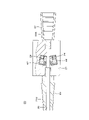
- FIG. 24 is a front view of the measurement adapter 20 of Embodiment 7.
- FIG. The measurement adapter 20 has a display section 35 on its side surface.
- 25 is a partial cross-sectional view taken along line XXV--XXV in FIG. 24.
- the measurement adapter 20 includes a first tubular portion 21 , a second tubular portion 22 and a third tubular portion 23 .
- the first tubular portion 21, the second tubular portion 22, and the third tubular portion 23 are connected in the longitudinal direction.
- a channel 28 is provided along the longitudinal direction of the measurement adapter 20 .
- the second cylindrical portion 22 has a substantially cylindrical shape and has a urine collection bag connecting portion 228 on the inner surface.
- the third tubular portion 23 has a substantially cylindrical shape and has a catheter connecting portion 218 on its outer surface.
- the third cylindrical portion 23 has a substantially prismatic outer diameter and has a flow path 28 inside.
- An optical sensor unit 42 and a flow rate measuring section 27 are built in the third cylindrical section 23 .
- the optical sensor unit 42 and the flow rate measuring section 27 are arranged facing the flow path 28 respectively. That is, the measurement adapter 20 of the present embodiment has an optical sensor unit holding portion that holds the optical sensor unit 42 inside the third cylindrical portion 23 and a flow rate sensor holding portion that holds the flow rate measuring portion 27 .
- FIG. 26 is an explanatory diagram for explaining the configuration of the optical sensor unit 42.
- the optical sensor unit 42 has a light shielding case 421 , a light source 51 , a detector 53 , a light emitter 24 and a plurality of filters 57 .
- the light shielding case 421 is a housing for the optical sensor unit 42 and covers portions other than the light emitter 24 .
- the light shielding case 421 is an example of a light shielding layer that covers the portion of the optical sensor unit 42 that does not face the flow path.
- a light shielding partition 422 for shielding light between the light source 51 and the detector 53 is provided inside the optical sensor unit 42 .
- the light emitter 24 and the optical sensor unit 42 are watertightly fixed.
- the light source 51 is, for example, a light emitting element such as an LED.
- the detector 53 is an element that detects light, such as a photodiode. Light source 51 and detector 53 are controlled by controller 31 .
- the optical sensor unit 42 is arranged so that the light emitter 24 contacts the urine flowing through the channel 28 .
- FIG. 27 is an explanatory diagram for explaining the configuration of the measurement adapter 20 of the seventh embodiment.
- the measurement adapter 20 includes a controller 31, a main memory device 32, an auxiliary memory device 33, a communication section 34, an input section 36, a battery 428, and a bus in addition to the flow rate measurement section 27, the optical sensor unit 42, and the display section 35. .
- the control unit 31, the main storage device 32, the auxiliary storage device 33, and the communication unit 34 have the same functions as the constituent elements included in the measuring device 30 described in Embodiment 1, so description thereof will be omitted.
- the display portion 35 is attached to the side surface of the first cylindrical portion 21 as shown in FIG. 24 .
- the input section 36 is a switch attached to the first tubular section 21 .
- the display unit 35 and the input unit 36 may be laminated to form a touch panel.
- the battery 428 supplies power to each electronic component that the control unit 31 configures the measurement adapter 20 .
- FIGS. 24 to 27 an outline of how to use the measurement adapter 20 of the present embodiment will be described.
- the user connects the indwelling bladder catheter 15 , the measurement adapter 20 and the urine collection bag 17 .
- the user inserts shaft 153 into the patient's urethra.
- the user inflates the balloon 152 while the tip of the shaft 153 is inside the bladder.
- the bladder indwelling catheter 15 is left in the patient.
- the patient's urine passes through side hole 151 , shaft 153 , channel 28 and urine collection tube 172 and collects in bag 171 .
- the user operates the input unit 36 to start measurement. Measurement may be initiated automatically in response to urine flowing through channel 28 . Light emitted from the light source 51 irradiates the light emitter 24 through the filter 57 . When the light emitter 24 contacts urine flowing through the channel 28, fluorescence is emitted.
- the fluorescence is converted into an electrical signal by the detector 53 and output to the bus.
- the control unit 31 analyzes the electrical signal and calculates items related to the phosphor. That is, the control unit 31 implements the functions of the optical analyzer 52 described in the first embodiment by software.
- the control unit 31 acquires the flow rate output to the bus from the flow rate measurement unit 27.
- the control unit 31 displays items and flow rates related to the phosphor on the display unit 35 .
- the oxygen partial pressure and flow rate in urine are displayed on the display section 35 .
- the measurement adapter 20 may include a thermometer or other sensor instead of the flow rate measurement section 27 or together with the flow rate measurement section 27 .
- the measurement adapter 20 may incorporate multiple optical sensor units 42 .
- the optical sensor unit 42 may include an optical analyzer 52 . In doing so, the photosensor unit 42 outputs the output of the photosensor 52 on the bus.
- the control unit 31 may transmit data to the outside via wireless communication and cause an external display device to display the same items as the display unit 35 .
- FIG. 28 is an explanatory diagram for explaining the configuration of the optical sensor unit 42 of Modification 7-1.
- the optical sensor unit 42 comprises a reference light source 54 near the detector 53 .
- the reference light source 54 is arranged at a position where the emitted light is directly incident on the detector 53 . By performing calibration or correction using the reference light source 54, the measurement system 10 with high measurement accuracy can be provided.
- FIG. 29 is an explanatory diagram illustrating the configuration of the optical sensor unit 42 of modification 7-2.
- the light source 51 is arranged such that the optical axis of the emitted excitation light forms an angle of approximately 45 degrees with respect to the longitudinal direction of the flow channel 28 .
- Excitation light is emitted from the light source 51 toward the flow path 28 via the light emitter 24 .
- the light emitter 24 is in contact with urine, the emitted excitation light is incident on the detector 53 through the filter 57 .
- the light shielding case 421 prevents the light in the fluorescence wavelength band included in the light emitted by the light source 51 from reaching the detector 53 . Therefore, it is possible to provide the measurement adapter 20 capable of highly accurate measurement.
- FIG. 30 is an explanatory diagram illustrating the configuration of the optical sensor unit 42 of Modification 7-3.
- the light source 51 is arranged such that the optical axis of the emitted excitation light forms an angle of approximately 45 degrees with respect to the longitudinal direction of the flow channel 28 .
- a reference light source 54 is arranged in the vicinity of the detector 53 .
- optical sensor unit 42 All of the modifications are illustrations of the arrangement of the components that make up the optical sensor unit 42.
- the configuration of the optical sensor unit 42 is not limited to these.
- FIG. 31 is a cross-sectional view of the measurement adapter 20 of modification 7-4.
- an inner diameter changing portion is provided in the central portion of the flow path 28 so that the inner diameter is tapered from the catheter connecting portion 218 side to the urine collection bag connecting portion 228 side.
- Two optical sensor units 42 are arranged facing each other outside the inner diameter changing portion. The light emitter 24 of each optical sensor unit 42 is in contact with the inner diameter changing portion.
- the inner diameter changing portion has a substantially oval cross section surrounded by, for example, two planes perpendicular to the paper surface of FIG.
- the inner diameter changing portion may have a circular cross section.
- the channel 28 may return to its original thickness on the downstream side of the change in inner diameter.
- the light emitter 24 By arranging the light emitter 24 in the inner diameter changing portion, it becomes easier for fresh urine to touch the light emitter 24 . Therefore, it is possible to provide the measurement system 10 capable of highly accurate measurement.
- the total length of the measurement adapter 20 can be kept short even when the two optical sensor units 42 are provided.
- optical sensor unit 42 and a sensor that does not use fluorescence may be arranged opposite to each other with the flow path 28 interposed therebetween.
- the light emitter 24 described in Embodiment 1 may be arranged in the inner diameter changing portion, and the optical fiber 41 may be attached to the measurement adapter 20 .
- the through hole through which the optical fiber 41 is inserted and fixed is substantially perpendicular to the inner diameter changing portion, that is, inclined with respect to the flow path 28 .
- the optical fiber 41 is attached to the measurement adapter 20 with the optical fiber 41 inclined toward the urine collection bag 17 side, it is possible to provide the measurement adapter 20 that can be easily fixed with the optical fiber 41 along the bag 171 .
- FIG. 32 is a perspective view of the measurement adapter 20 of modification 7-5.
- the measurement adapter 20 of this modified example operates by receiving power from the power cable 429 .
- the display section 35 is arranged obliquely with respect to the long axis of the channel 28 .
- a connector to which the power cable 429 is connected is arranged at the end portion of the display portion 35 on the second cylindrical portion 22 side.
- Three input portions 36 are arranged on the side surface of the first tubular portion 21 .
- the input unit 36 is, for example, a power switch, a changeover switch for items displayed on the display unit 35, a measurement start switch, and the like.
- the indwelling bladder catheter 15 is indwelled for a long period of time such as 4 weeks, it is possible to provide the measurement adapter 20 that does not run out of battery. Power may be supplied to the measurement adapter 20 by wireless power supply.
- the power cable 429 may be a so-called composite cable including the optical fiber 41.
- a light guide path for propagating the light supplied from the optical fiber 41 to the optical sensor unit 42 is arranged inside the measurement adapter 20 . Since there is no need to mount a light source such as an LED, the size of the optical sensor unit 42 can be reduced.
- FIG. 33 is a functional block diagram of the measurement system 10 of Embodiment 8.
- the measurement system 10 has a measurement adapter 20 and a measurement device 30 .
- the measurement adapter 20 is arranged between a catheter connection portion 218 connectable to the indwelling bladder catheter 15, a urine collection bag connection portion 228 connectable to the urine collection bag 17, and between the catheter connection portion 218 and the urine collection bag connection portion 228.
- the measuring device 30 has a channel 28 and a plurality of sensor holders 91 holding sensors 24 and 45 capable of detecting the state of urine flowing through the channel 28 .
- a data acquisition unit 92 that acquires data from 24 and 45, and a display unit 35 that displays information about the patient in whom the bladder indwelling catheter 15 is indwelled based on the acquired data.
Abstract
既存の膀胱留置カテーテルと組み合わせて尿の状態を測定可能な測定アダプタ等を提供すること。 測定アダプタ(20)は、膀胱留置カテーテルに接続可能なカテーテル接続部(218)と、採尿バッグに接続可能な採尿バッグ接続部(228)と、前記カテーテル接続部(218)と前記採尿バッグ接続部(228)との間に配置された流路(28)と、前記流路(28)内を流れる尿の状態を検知可能なセンサ(24、45)を保持する複数のセンサ保持部とを備える。
Description
本発明は、測定アダプタ、測定システムおよび測定方法に関する。
様々な仕様の膀胱留置カテーテルが医療現場で使用されている。医師は、患者の性別、年齢、体格および容体等に基づいて、適切な仕様の膀胱留置カテーテルを選択して、使用する。
酸素センサを搭載した膀胱留置カテーテルが提案されている。尿中の酸素分圧をリアルタイムで測定することにより、急性腎障害の兆候を早期に発見できる(特許文献1)。
しかしながら、特許文献1の膀胱留置カテーテルを使用する場合、医師は、既存の膀胱留置カテーテルほどのバリエーションから、適切な膀胱留置カテーテルを選択できない。
一つの側面では、既存の膀胱留置カテーテルと組み合わせて尿の状態を測定可能な測定アダプタ等を提供することを目的とする。
測定アダプタは、膀胱留置カテーテルに接続可能なカテーテル接続部と、採尿バッグに接続可能な採尿バッグ接続部と、前記カテーテル接続部と前記採尿バッグ接続部との間に配置された流路と、前記流路内を流れる尿の状態を検知可能なセンサを保持する複数のセンサ保持部とを備える。
一つの側面では、既存の膀胱留置カテーテルと組み合わせて尿の状態を測定可能な測定アダプタ等を提供できる。
[実施の形態1]
図1は、測定システム10の構成を説明する説明図である。測定システム10は、膀胱留置カテーテル15、採尿バッグ17、測定アダプタ20および測定装置30を含む。なお、図1は測定システム10の各構成要素を模式的に示す図である。
図1は、測定システム10の構成を説明する説明図である。測定システム10は、膀胱留置カテーテル15、採尿バッグ17、測定アダプタ20および測定装置30を含む。なお、図1は測定システム10の各構成要素を模式的に示す図である。
膀胱留置カテーテル15は、先端に側孔151およびバルーン152を有するシャフト153と、シャフト153の一端に接続された排尿用ファネル154とを含む。採尿バッグ17は、バッグ171と、採尿チューブ172と、接続筒173とを含む。本実施の形態の膀胱留置カテーテル15および採尿バッグ17は、従来から医療現場で使用されている。従来の膀胱留置カテーテル15および採尿バッグ17の使用方法の概要を説明する。
医師等のユーザは、排尿用ファネル154と、接続筒173とを接続した後に、患者の尿道にシャフト153を挿入する。シャフト153の先端が膀胱の内部に入った状態で、ユーザはバルーン152を膨らませる。図1に示すバルーン152は、膨らんだ状態である。バルーン152を膨らませることにより、シャフト153は尿道から抜けない状態になる。患者の尿は、側孔151、シャフト153および採尿チューブ172を通って、バッグ171に溜まる。
本実施の形態においては、図1に示すように排尿用ファネル154と接続筒173との間に、測定アダプタ20が接続されている。患者の尿は、側孔151、シャフト153、測定アダプタ20および採尿チューブ172を通って、バッグ171に溜まる。
測定装置30は、表示部35、第1コネクタ371および第2コネクタ372を有する。図1に示す例では、表示部35に患者の尿中の酸素分圧(pO2)、および、測定アダプタ20内を流れる尿の温度がリアルタイムで表示されている。
測定アダプタ20には、光ファイバ41および熱電対45が接続されている。熱電対45は、温度センサの例示である。光ファイバ41および熱電対45は、留具49により3か所で採尿チューブ172に固定されている。光ファイバ41の端部に設けられた光ファイバコネクタ411は、第1コネクタ371に接続されている。熱電対45の端部に設けられた熱電対コネクタ452は、第2コネクタ372に接続されている。
図2は、測定アダプタ20の断面図である。図3は、図2におけるIII矢視図である。測定アダプタ20は、第1筒部21と第2筒部22とを備える。第1筒部21と第2筒部22とは長手方向に連結されている。測定アダプタ20長手方向に沿って、貫通孔である流路28が設けられている。側孔151からシャフト153の内部に入った尿は、流路28を通って、採尿チューブ172に入る。
第1筒部21は略円筒形であり、側面に突出する第1接続部211および第2接続部212を有する。第1接続部211および第2接続部212の外周には、それぞれ雄ネジが設けられている。第1接続部211および第2接続部212には、流路28まで貫通する貫通孔が設けられている。第1接続部211と第2接続部212は、流路28の長手方向に沿って並んで配置されている。
第1接続部211に設けられた貫通孔の外周側の端部には、外側に広がる段が設けられている。段の内側に、円筒形状の保持ゴム252が挿入されている。貫通孔の流路28に近い側に太径部分が設けられている。太径部分には、発光体24が収容されている。発光体24は、流路28を流れる尿に接触する。発光体24の縁は、第1筒部21に水密に接着固定されており、第1接続部211に設けられた孔から尿が漏れることが防止されている。発光体24については後述する。
第1筒部21は、一端の外面に先細りのテーパ状であるカテーテル接続部218を有する。カテーテル接続部218には、抜け止めの突起が筋状に設けられている。第1筒部21は硬質であり、たとえば硬質プラスチック製である。カテーテル接続部218は、従来から使用されている採尿バッグ17の接続筒173と同様に、膀胱留置カテーテル15の排尿用ファネル154に接続可能な寸法および形状である。
第2筒部22は、一端の内面に先拡がりのテーパ状である採尿バッグ接続部228を有する。採尿バッグ接続部228の表面には、抜け止めの突起が筋状に設けられている。第2筒部22は、ゴム製またはエラストマー製であり、ゴム弾性を有する。第2筒部22を構成する材料は、たとえばスチレン系、オレフィン系またはポリエステル系のエラストマーである。採尿バッグ接続部228は、従来から使用されている膀胱留置カテーテル15の排尿用ファネル154と同様に、採尿バッグ17の接続筒173に接続可能な寸法および形状である。
第1筒部21および第2筒部22は、既存の膀胱留置カテーテル15と採尿バッグ17との接続部に使用されている材料と同一の材料製であることが、さらに望ましい。これらの既存の器具には、シリコーンゴムエラストマー、および、ウレタンゴムエラストマー等が使用されている。
したがって、測定アダプタ20は従来から使用されている膀胱留置カテーテル15と採尿バッグ17との間に取り付け可能である。ユーザは、患者の容体等に応じて適宜選択した膀胱留置カテーテル15および採尿バッグ17を、測定アダプタ20と組み合わせて使用できる。
第1筒部21と第2筒部22とは、たとえば接着またはネジ止めにより水密に固定されている。第1筒部21と第2筒部22とは、異種材料の一体成型により形成されていてもよい。
第1接続部211には、天面に貫通孔を有する第1キャップ251が取り付けられている。第1キャップ251の内面には第1接続部211と螺合する雌ネジが設けられている。第2接続部212には、天面に貫通孔を有する第2キャップ262が取り付けられている。第2キャップ262の内面には、第2接続部212と螺合する雌ネジが設けられている。図2および図3においては、第1キャップ251および第2キャップ262のネジは緩められている。
発光体24は、たとえば蛍光体が練り込まれた透光性樹脂製の板である。発光体24は、蛍光体が塗布された透光性の板であってもよい。本実施の形態においては、尿中の酸素に反応して蛍光を発する蛍光体を使用する場合を例にして説明する。蛍光は、発光体24が放射する放射光の例示である。蛍光体が発する蛍光の特性を解析することにより、尿中の酸素分圧および酸素濃度をリアルタイムで測定できる。
蛍光体を用いた測定手法の概要について説明する。励起光が照射された場合、蛍光体はエネルギーの高い励起状態になる。励起状態である蛍光体から、蛍光が放射されて、蛍光体は基底状態に戻る。放射される蛍光の強度、位相角および減衰時間等の蛍光の特性は、蛍光体が接触した消光体の濃度と、周囲の温度および気圧等の環境とに基づいて変化する。したがって、放射光の特性を解析することにより、消光体の濃度、および周囲の温度等を測定できる。
消光体は、たとえば酸素である。たとえば、発光体24の表面に配置される拡散浸透膜により、蛍光体に接触する消光体、すなわち測定対象成分を選択できる。特定の消光体と反応する蛍光体が使用されてもよい。なお蛍光体が発する放射光には、燐光も含まれる。燐光の特性を解析することにより、測定が行われてもよい。
発光体24は、流路28に面する部分だけに蛍光体を有してもよい。発光体24は、流路28に面する部分に突起を有してもよい。突起を有することにより、流路28内を流れる尿に発光体24が確実に接触する。
蛍光体は、尿中の二酸化炭素に反応して蛍光を発してもよい。蛍光の特性を解析することにより、尿中の二酸化炭素分圧および二酸化炭素濃度をリアルタイムで測定できる。蛍光体は、尿の水素イオン指数によって発する蛍光の特性が変化してもよい。蛍光の特性を解析することにより、尿の水素イオン指数、すなわちpH(potential of Hydrogen)をリアルタイムで測定できる。
蛍光体は、尿中のカリウムイオンまたはナトリウムイオン等のイオンに反応して蛍光を発してもよい。蛍光の特性を解析することにより、尿中の電解質の濃度をリアルタイムで測定できる。そのほか、尿中の任意の成分と反応して蛍光を発する蛍光体を使用してもよい。
前述の通り、蛍光体は、温度により蛍光の特性が変化する。蛍光の特性を解析することにより、尿の温度をリアルタイムで測定できる。蛍光体は、接触する尿の流量により発光状態が変化してもよい。蛍光の特性を解析することにより、尿の流量をリアルタイムで測定できる。
図4は、測定アダプタ20の構造を説明する説明図である。図4においては、第1接続部211に設けられた貫通孔に光ファイバ41の先端が、第2接続部212に設けられた貫通孔に熱電対45の先端がそれぞれ挿入されている。
光ファイバ41の先端は、発光体24に突き当てられている。第1キャップ251が締め込まれて、保持ゴム252が図4における上下方向に圧縮されている。圧縮された保持ゴム252は、径方向、すなわち図4における左右方向に膨らみ、光ファイバ41の側面を押圧して固定する。
第1キャップ251を緩めることにより、保持ゴム252は元の形状に戻り、光ファイバ41は測定アダプタ20から取り外せる状態になる。すなわち、光ファイバ41は測定アダプタ20に対して着脱可能である。
熱電対45の先端に設けられた測温接点451が流路28の内部に配置されている。第2キャップ262が締め込まれて、図示を省略する液密ゴムにより熱電対45が液密に保持される。
第1接続部211に設けられた貫通孔および第2接続部212に設けられた貫通孔は、いずれも本実施の形態のセンサ保持部の例示である。第1接続部211に設けられた貫通孔のうち、発光体24が収容された太径部分は、本実施の形態の発光体保持部の例示である。第1接続部211に設けられた貫通孔のうち、外側の段付部および段付き部配置された保持ゴム252は、本実施の形態の光ファイバ保持部の例示である。第2接続部212に設けられた貫通孔は、温度センサ保持部の例示である。
第1筒部21は、たとえば発光体24が収容された太径部分が表面まで開口した部材と、第1接続部211を含む段付き筒状の部材との2つの部材により構成されている。2つの部材の境界を図4に記号Bを付した二点鎖線で示す。太径部分の底に発光体24を配置した後に、段付き筒状の部材を接着固定することにより、第1筒部21を製作できる。
図2から図3を使用して説明した、光ファイバ41および熱電対45の固定構造はいずれも例示である。測定アダプタ20の使用中に、光ファイバ41および熱電対45の位置ズレを防止できる任意の構造を採用できる。たとえば、光ファイバ41および熱電対45の表面にそれぞれ形成された凸凹と、測定アダプタ20に形成された凹凸とが勘合する構造であってもよい。
光ファイバ41と測定アダプタ20とを着脱する必要が無い場合には、接着剤を用いて両者が固定されていてもよい。熱電対45と測定アダプタ20とを着脱する必要が無い場合には、接着剤を用いて両者が液密を確保できる状態に固定されていてもよい。セッティングが容易な測定アダプタ20を提供できる。
第1接続部211の設けられた貫通孔、および、第2接続部212に設けられた貫通孔は、流路28に対して傾斜していても良い。そのようにすることにより、光ファイバ41および熱電対45を測定アダプタ20に対して斜めに取り付けられる。たとえば、光ファイバ41および熱電対45が測定アダプタ20に対して採尿バッグ17側に傾斜した状態で取り付けられている場合、光ファイバ41および熱電対45を、採尿チューブ172に沿わせやすい。したがって、光ファイバ41および熱電対45が外れにくい測定アダプタ20を提供できる。
なお、図4にAで示す部分、すなわちいずれのセンサ保持部よりもカテーテル接続部218に近い側に、流路28内の尿の逆流を防止する逆止弁が設けられていてもよい。バッグ171から膀胱への尿の逆流を防止することにより、尿路感染症の発生リスクを低減できる。
図5は、測定装置30の構成を説明する説明図である。測定装置30は、表示部35、第1コネクタ371および第2コネクタ372に加えて、制御部31、主記憶装置32、補助記憶装置33、通信部34、入力部36、温度計測機39、光源51、光解析器52、導光路55、ビームスプリッタ56およびバスを備える。制御部31は、本実施の形態のプログラムを実行する演算制御装置である。制御部31には、一または複数のCPU(Central Processing Unit)、GPU(Graphics Processing Unit)またはマルチコアCPU等が使用される。制御部31は、バスを介して測定装置30を構成するハードウェア各部と接続されている。
主記憶装置32は、SRAM(Static Random Access Memory)、DRAM(Dynamic Random Access Memory)、フラッシュメモリ等の記憶装置である。主記憶装置32には、制御部31が行なう処理の途中で必要な情報および制御部31で実行中のプログラムが一時的に保存される。
補助記憶装置33は、SRAM、フラッシュメモリ、ハードディスクまたは磁気テープ等の記憶装置である。補助記憶装置33には、制御部31に実行させるプログラムおよびプログラムの実行に必要な各種データが保存される。通信部34は、測定装置30とネットワークまたは他の機器との間の通信を行なうインターフェイスである。
表示部35は、たとえば液晶表示パネルまたは有機EL(electro-luminescence)パネル等である。表示部35は、図1に示すように測定装置30の筐体に取り付けられている。表示部35は、測定装置30とは別体の表示装置であってもよい。たとえば生体情報モニタ等の他の機器の画面が、表示部35を兼ねてもよい。
入力部36は、測定装置30の筐体に設けられたボタン等である。表示部35と入力部36とは、一体になったパネルであってもよい。第1コネクタ371は、光ファイバ41が接続される光コネクタである。第2コネクタ372は、熱電対45が接続される電気コネクタである。測定装置30は、複数の第1コネクタ371を備えてもよい。
光源51は、たとえばLED(light emitting diode)またはレーザダイオードである。光源51は、発光体24に励起光を照射して、発光体24に含まれる蛍光体を励起させる。励起光は、光源51から発光体24に照射される照射光の例示である。光源51が放射する光には、蛍光体が放射する蛍光の波長は殆ど含まれない。
光解析器52は、受光した光をたとえばフォトダイオードにより電気信号に変換した後に解析を行なう。光源51とビームスプリッタ56との間、光解析器52とビームスプリッタ56との間、およびビームスプリッタ56と第1コネクタ371との間は、それぞれ導光路55により接続されている。
温度計測機39は、第2コネクタ372に接続されている。温度計測機39は、第2コネクタ372に接続された熱電対45に生じる熱起電力に基づいて、測温接点451付近の温度を計測して、バスに出力する。熱電対45による温度計測は従来から行われているため、詳細については説明を省略する。熱電対45の代わりに、たとえばサーミスタ、測温抵抗体または蛍光体等、温度を測定可能な任意のセンサが、温度計測機39に接続されていてもよい。
光源51とビームスプリッタ56との間に配置された導光路55の途中または導光路55の端部に、蛍光体を励起させるために必要な波長域のみを透過させる光学フィルタが設けられていてもよい。波長域が広い光源51を使用した場合であっても、発光体24に照射する励起光の波長域を精密に選択できる。励起光以外の波長によるノイズが生じないため、測定精度の高い測定装置30を提供できる。
導光路55の途中または導光路55の端部に、光学レンズが配置されていてもよい。励起光および蛍光を有効に利用することにより、測定感度の高い測定装置30を提供できる。
測定装置30は、励起光用の光を放射する光源51に加えて、光解析器52に参照光を供給する第2光源を有しても良い。参照光を用いた解析を行なう測定装置30を提供できる。第2光源から照射された参照光は、光解析器52に直接入射する。第2光源と光解析器52との間は、たとえば専用の導光路により接続される。第2光源と光解析器52との間は、第2光源から照射された光が光解析器52に入射するように構成された空洞であってもよい。
測定装置30は、複数の第2コネクタ372および温度計測機39を備えてもよい。測定装置30は、流量計または圧力計等の任意の計測器と、当該計測器に対応するセンサを接続するコネクタとを備えていてもよい。
図6は、留具49の斜視図である。留具49は、第1部品491と第2部品492とを備える。第1部品491は、略C字型の採尿チューブ保持部496を有する。第2部品492は、採尿チューブ保持部496の外側に取り付けられている。第2部品492は、それぞれスリットの底に配置された光ファイバ保持部497と熱電対保持部498とを有する。
採尿チューブ保持部496は、採尿チューブ172の外周に嵌め込める寸法である。光ファイバ保持部497は、スリットから押し込まれた光ファイバ41を保持できる寸法である。熱電対保持部498は、スリットから押し込まれた熱電対45を保持できる寸法である。
第1部品491を構成する第1材料は、硬質プラスチック等の、比較的硬くてしなりやすい材料であることが望ましい。第2部品492を構成する第2材料は、たとえばゴム等のエラストマーであることが望ましい。第1材料は第2材料よりも軟質の材料であってもよい。第1部品491と第2部品492とは、同一の材料により一体に形成されていてもよい。
図1を使用して説明したように光ファイバ41および熱電対45は、留具49により3か所で採尿チューブ172に固定される。留具49の代わりにたとえば医療用テープ等を用いて光ファイバ41および熱電対45が固定されてもよい。光ファイバ41および熱電対45は、点滴台またはベッドの柵等の任意の場所に固定されてもよい。
図1を使用して、測定システム10の使用方法の概要を説明する。ユーザは、膀胱留置カテーテル15と、測定アダプタ20と、採尿バッグ17とを接続する。ユーザは、測定アダプタ20および測定装置30に、光ファイバ41および熱電対45をそれぞれ接続する。ユーザは、留具49を用いて光ファイバ41および熱電対45を採尿チューブ172に固定する。
ユーザは、患者の尿道にシャフト153を挿入する。シャフト153の先端が膀胱の内部に入った状態で、ユーザはバルーン152を膨らませる。以上により、膀胱留置カテーテル15が患者に留置される。患者の尿は、側孔151、シャフト153、流路28および採尿チューブ172を通って、バッグ171に溜まる。
図5を使用して説明を続ける。ユーザは、測定装置30を操作して光源51を動作させる。光源51から放射された励起光は、導光路55、ビームスプリッタ56および光ファイバ41を介して発光体24に照射される。発光体24が流路28を流れる尿に接触した場合、尿中の酸素に応じた蛍光が発光する。すなわち、発光体24は尿中の酸素分圧および酸素濃度を検知可能なセンサの機能を果たす。
蛍光は、光ファイバ41および導光路55を介してビームスプリッタ56に入射する。すなわち、光ファイバ41は光源51から発光体24に照射される光と、発光体24から放射された光とを伝搬する機能を有する。ビームスプリッタ56により蛍光は光解析器52に繋がる導光路55に入射する。光解析器52は、入射した蛍光の特性を解析して、尿中の酸素分圧または酸素濃度をリアルタイムでバスに出力する。
制御部31は、温度計測機39から出力された温度と、光解析器52から出力された尿中の酸素分圧とを表示部35に表示する。
図7は、プログラムの処理の流れを説明するフローチャートである。制御部31は、ユーザが光源51を動作させる指示を行なった場合に図7のプログラムを起動する。
制御部31は、光源51をON状態にする(ステップS501)。ビームスプリッタ56および光ファイバ41を介して発光体24に励起光が照射される。発光体24の蛍光体から放射された蛍光は、光ファイバ41、およびビームスプリッタ56を介して光解析器52に入射する。光解析器52は、蛍光に基づいて尿中酸素分圧データを出力する。制御部31は、光解析器52から尿中酸素分圧データを取得する(ステップS502)。
温度計測機39は、熱電対45の熱起電力に基づいて温度データを出力する。制御部31は、温度計測機39から温度データを取得する(ステップS503)。ステップS502およびステップS503により、制御部31はセンサ保持部に保持されたセンサからデータを取得するデータ取得部の機能を実現する。
制御部31は、図1に例示するように、表示部35に尿中酸素分圧および温度を表示する(ステップS504)。制御部31は、処理を終了するか否かを判定する(ステップS505)。たとえば制御部31は光源51をOFFにする操作を受け付けた場合、光ファイバ41を第1コネクタ371から取り外した場合、または熱電対45を第2コネクタ372から取り外した場合に、処理を終了すると判定する。
処理を終了すると判定した場合(ステップS505でYES)、制御部31は光源51をOFFにする(ステップS506)。制御部31は、処理を終了する。処理を終了しないと判定した場合(ステップS505でNO)、制御部31はステップS502に戻る。
本実施の形態によると、既存の膀胱留置カテーテル15および採尿バッグ17と組み合わせて、尿中の酸素分圧等をリアルタイムで測定可能な測定アダプタ20を提供できる。ユーザは、患者の状態、過去の経験および専門知識等に基づいて選択した膀胱留置カテーテル15を、本実施の形態の測定アダプタ20と組み合わせて使用できる。
尿中の酸素分圧をリアルタイムで測定することにより、急性腎障害に至る兆候を早期に発見できる。尿量および血清クレアチン値、またはバイオマーカーを用いる従来の手法に比べて、早い段階で急性腎障害を発見し、適切な治療を行なえる。
制御部31は、たとえば尿中の酸素分圧が閾値以下になった場合に、ユーザに対して通知を行なってもよい。たとえば制御部31は、たとえば表示部35への表示、または、測定装置30からの音声出力によりユーザへの通知を行なう。制御部31は、HIS(Hospital Information System)、または、EMR(Electronic Medical Record)等のネットワークを介して、ナースステーション等に通知を送信してもよい。
制御部31は、たとえば、尿中の酸素分圧と温度とに基づいて、腎臓等の泌尿器の状態を表わす指標を算出して、表示部35に表示してもよい。泌尿器の状態を表わす指標は、たとえば生体情報モニタ等の他の機器から取得した情報と、尿中の酸素分圧および温度とを組み合わせて算出されてもよい。指標は、泌尿器に限らず、患者の全身の状態を表わす指標であってもよい。このようにする場合、制御部31は泌尿器の状態を表わす指標を算出する指標算出部の機能を実現する。
光解析器52は、受光した蛍光の強度、位相角および減衰時間等の、蛍光の特性を示すデータをバスに出力してもよい。そのようにする場合には、制御部31が尿中酸素分圧または尿中酸素濃度等を算出する。温度計測機39は、熱起電力の電圧値を示すデータをバスに出力してもよい。そのようにする場合には、制御部31が電圧値に基づいて温度を算出する。
光源51、光解析器52、導光路55、ビームスプリッタ56および第1コネクタ371で構成された、光解析ブロックは、測定装置30と別体であってもよい。温度計測機39および第2コネクタ372で構成された、温度測定ブロックは測定装置30と別体であってもよい。
光解析ブロックおよび温度測定ブロックの両方が別体である場合、パソコン、タブレット、スマートフォン等の汎用の情報処理装置と、光解析ブロックと、温度測定ブロックとを組み合わせて、本実施の形態の測定装置30を構成してもよい。そのようにする場合、光解析ブロックおよび温度測定ブロックと、情報処理装置との間は、有線または無線により接続される。
なお、図1に示す表示部35の表示は例示である。たとえば、発光体24がカリウムイオンに反応する蛍光体を有する場合、測定装置30は、尿中のカリウムイオン濃度を表示部35にリアルタイムで標示する。
測定アダプタ20は、滅菌された状態でユーザに供給される単回使用製品であることが望ましい。このようにすることにより、尿路感染症の発生リスクを低減できる。
測定アダプタ20は、膀胱留置カテーテル15の代わりにたとえば胸腔ドレナージチューブ、腹腔ドレナージチューブ、または、脳ドレナージチューブ等、患者から体液等を継続的に排出させる際に用いられる任意のチューブに取り付けられてもよい。測定アダプタ20は、輸液チューブまたは栄養チューブ等、患者の体内に液体を送る際に用いられる任意のチューブに取り付けられても良い。
[変形例1-1]
本変形例は、時系列データを表示部35に表示する測定システム10に関する。実施の形態1と共通する部分については、説明を省略する。
本変形例は、時系列データを表示部35に表示する測定システム10に関する。実施の形態1と共通する部分については、説明を省略する。
図8は、変形例1-1の画面例である。本変形例においては、比較的大きな表示部35が使用される。画面には、指標欄67、日時欄61、酸素分圧欄62、温度欄63およびグラフ欄68が表示されている。指標欄67には、腎臓の状態を表わす指標が表示されている。アルファベットと「+」または「-」の記号の組み合わせにより、ユーザは患者の腎臓の状態を容易に把握できる。
日時欄61には、日付、曜日および時刻が表示されている。酸素分圧欄62には、尿中の酸素分圧が表示されている。温度欄63には、温度が表示されている。グラフ欄68には、尿中の酸素分圧および温度の時系列データが、それぞれ折れ線グラフにより表示されている。図8においては、破線は尿中の酸素分圧の時系列データを示し、実線は温度の時系列データを示す。酸素分圧欄62の「pO2」の文字の下に表示された破線、および「温度」の文字の下に表示された実線が、いわゆる凡例欄の機能を果たす。ユーザは、どのグラフが何を意味しているかを、容易に把握できる。
グラフ欄68に示す折れ線グラフは、グラフの形式の例示である。ユーザが臨床現場で使用しやすい任意の形式のグラフをグラフ欄68に使用できる。たとえば、単位時間あたりの値が重要視される場合には、グラフ欄68の表示に棒グラフを使用する。ユーザが、グラフの形式を適宜指定できてもよい。
時系列データは、グラフ形式の代わりに表形式で標示されてもよい。なお制御部31は、ユーザによる表示部35に表示する項目およびレイアウトの設定変更を適宜受け付けてもよい。ユーザは、状況に応じて使いやすい設定で測定システム10を使用できる。
[変形例1-2]
本変形例は、光ファイバ41が照射光用のファイバと、受光用のファイバとに分かれた測定システム10に関する。実施の形態1と共通する部分については、説明を省略する。
本変形例は、光ファイバ41が照射光用のファイバと、受光用のファイバとに分かれた測定システム10に関する。実施の形態1と共通する部分については、説明を省略する。
図9は、変形例1-2の構成を説明する説明図である。光ファイバ41は、端部で二束に分けられており、一方の束に蛍光コネクタ413が、他方の束に照射光コネクタ414が接続されている。
測定装置30は、第1コネクタ371の代わりに第3コネクタ373および第4コネクタ374を備える。第3コネクタ373は、導光路55を介して光解析器52に接続されている。第4コネクタ374は、導光路55を介して光源51に接続されている。
光源51から放射された励起光は、導光路55、第4コネクタ374、照射光コネクタ414を介して発光体24を照射する。発光体24から放射された蛍光は、光ファイバ41、蛍光コネクタ413、第1コネクタ371および導光路55を介して光解析器52に入射する。
照射光用(励起光用)と、受光用(蛍光用)とに共通して用いられる1本の共通ファイバに、照射光用のファイバと受光用のファイバとがカップリングされていてもよい。照射光用のファイバと、受光用のファイバとは別々であり、測定アダプタ20に取り付ける側で両者が束ねられていてもよい。照射光用のファイバには、励起光の伝搬に適した仕様のファイバが使用され、受光用のファイバには、蛍光の伝搬に適した仕様のファイバが使用されてもよい。
[変形例1-3]
本変形例は、光ファイバ41および熱電対45が挿通された留具49に関する。実施の形態1と共通する部分については、説明を省略する。
本変形例は、光ファイバ41および熱電対45が挿通された留具49に関する。実施の形態1と共通する部分については、説明を省略する。
図10は、変形例1-3の構成を説明する説明図である。留具49は、略C字形状の採尿チューブ保持部496と、丸穴形状の光ファイバ保持部497および熱電対保持部498を有する。熱電対45が熱電対保持部498に挿通されている。なお、図示を省略するが、光ファイバ41および熱電対45は、複数の留具49に挿通されている。
本変形例によると、測定アダプタ20および測定装置30への光ファイバ41および熱電対45の接続から、留具49による光ファイバ41および熱電対45の固定までをスムーズに行なえる測定システム10を提供できる。
[変形例1-4]
本変形例は、カバー29を備える測定アダプタ20に関する。実施の形態1と共通する部分については、説明を省略する。
本変形例は、カバー29を備える測定アダプタ20に関する。実施の形態1と共通する部分については、説明を省略する。
図11は、変形例1-4の測定アダプタ20の構造を説明する説明図である。測定アダプタ20の側面に、カバー29が取り付けられている。カバー29は、測定アダプタ20よりも太いチューブ状であり、測定アダプタ20の側面に適宜タックを設けて取り付けられている。カバー29の端部に、取付部291が取り付けられている。本変形例においては、取付部291はカバー29を引き絞ることが可能な紐である。
カバー29に設けられた孔から、第1キャップ251および第2キャップ262が突出している。図11に示すように、測定アダプタ20は、カバー29が複数回折りたたまれた状態でユーザに供給される。
図12は、変形例1-4の測定システム10の使用方法を説明する説明図である。ユーザは、膀胱留置カテーテル15と、測定アダプタ20と、採尿バッグ17とを接続する。ユーザは、測定装置30に、光ファイバ41および熱電対45をそれぞれ接続する。ユーザは、留具49を用いて光ファイバ41および熱電対45を採尿チューブ172に固定する。
ユーザは、折りたたまれたカバー29を広げて、膀胱留置カテーテル15と測定アダプタ20との接続部、および測定アダプタ20と採尿バッグ17との接続部をそれぞれ覆う。ユーザは、取付部291を引き絞って結ぶ。図12は、以上の工程が終了した段階を示す。なお、取付部291の代わりに医療用テープ等によりカバー29が固定されてもよい。
取付部291は、カバー29を引き絞ることが可能な紐に限定しない。たとえば取付部291は、カバー29の端部に取り付けられたゴムなどであってもよい。取付部291は、カバー29の内側に取り付けられた粘着テープであってもよい。取付部291は、簡易的な加熱によりチューブ状に収縮する素材で構成されていてもよい。
その後、ユーザは、光ファイバ41および熱電対45を測定アダプタ20に接続する。以上により、測定システム10の使用準備が完了する。
本変形例によると、膀胱留置カテーテル15と測定アダプタ20との接続部、および、測定アダプタ20と採尿バッグ17との接続部からの雑菌等の侵入による尿路感染症の発生リスクを低減できる。
測定アダプタ20は、第1キャップ251および保持ゴム252が、光ファイバ41および熱電対45と共にカバー29により覆われる形状であってもよい。さらに、尿路感染症の発生リスクを低減できる。
[実施の形態2]
本変形例は、光ファイバ41の端部に発光体24が取り付けられた測定システム10に関する。実施の形態1と共通する部分については、説明を省略する。
本変形例は、光ファイバ41の端部に発光体24が取り付けられた測定システム10に関する。実施の形態1と共通する部分については、説明を省略する。
図13は、実施の形態2の測定アダプタ20の構造を説明する説明図である。第1接続部211に設けられた貫通孔には、発光体24を収容する太径部分が設けられていない。測定アダプタ20は、第2接続部212を有さない。測定アダプタ20には、流量測定部27が内蔵されている。
流量測定部27は、流路28を流れる尿の流量を測定する流量センサの機能を果たす。測定アダプタ20のうち、流量測定部27を保持する部分は、流量センサを保持する流量センサ保持部の機能を果たす。流量測定部27は、たとえば光学式流量センサを用いてレーザードップラー法により流量を測定する光学式流量計、または、超音波流量センサを用いて超音波ドップラー法により流量を測定する超音波流量計である。流量測定部27は、熱式流量センサであってもよい。流量測定部27は、導尿された尿の重さの経時変化を取得して、尿流量を測定してもよい。流量測定部27は、無線通信機能を備える。
図14は、実施の形態2の測定システム10の構成を説明する説明図である。図14は測定システム10の各構成要素を模式的に示す図である。
測定装置30は、制御部31、主記憶装置32、補助記憶装置33、通信部34、入力部36、光源51、光解析器52、導光路55、ビームスプリッタ56、第1コネクタ371およびバスを備える。測定装置30は、無線通信を介して流量測定部27から流量を受信する。
測定装置30は、有線接続を介して流量測定部27から流量を受信してもよい。流量測定部27からたとえば超音波ドプラ信号を送信し、制御部31が信号解析を行なって流量を算出してもよい。
図15は、図14におけるXV部拡大図である。光ファイバ41の端面に、接着層241を介して発光体24が接着されている。発光体24は、たとえば蛍光体が練り込まれた透光性樹脂製の板である。発光体24は、蛍光体が塗布された透光性の板であってもよい。また、発光体24の液体が触れる側には、酸素等の消光体は透過するが、環境光を遮光する遮光層が配置されていてもよい。遮光層を設けることにより、環境光による蛍光体の劣化を防止できる。遮光層は、たとえばカーボンブラックにより構成される。
[変形例2-1]
図16は、変形例2-1の光ファイバ先端部の構成を説明する断面図である。図16は、図15と同様の部分の拡大図を示す。本変形例においては、光ファイバ41の端部が発光体24で覆われている。
図16は、変形例2-1の光ファイバ先端部の構成を説明する断面図である。図16は、図15と同様の部分の拡大図を示す。本変形例においては、光ファイバ41の端部が発光体24で覆われている。
たとえば、蛍光体が練り込まれた未硬化の透明性樹脂に光ファイバ41の先端を浸して、引き上げた後に硬化させることで、本変形例の光ファイバ41を製作できる。モールド型を用いて、蛍光体が練り込まれた透明性樹脂を光ファイバ41の先端に成形してもよい。
[変形例2-2]
図17は、変形例2-2の光ファイバ先端部の構成を説明する断面図である。図17は、図15と同様の部分の拡大図を示す。本変形例においては、光ファイバ41の端部に対して略垂直に、板状の発光体24が固定されている。
[変形例2-2]
図17は、変形例2-2の光ファイバ先端部の構成を説明する断面図である。図17は、図15と同様の部分の拡大図を示す。本変形例においては、光ファイバ41の端部に対して略垂直に、板状の発光体24が固定されている。
光ファイバ41の端部と発光体24とは、たとえば透光性樹脂を用いた接着層241で固定されている。接着層241の代わりに、所定の形状の透光性部品を光ファイバ41と発光体24との間に接着固定してもよい。
発光体24を膀胱留置カテーテル15側に向けた状態で、光ファイバ41を第1接続部211に固定することにより、新鮮な尿が発光体24に触れやすくなる。したがって、感度の高い測定システム10を提供できる。
[実施の形態3]
本実施の形態は、励起光と蛍光とを分離するフィルタ57を備える測定装置30に関する。実施の形態1と共通する部分については、説明を省略する。
本実施の形態は、励起光と蛍光とを分離するフィルタ57を備える測定装置30に関する。実施の形態1と共通する部分については、説明を省略する。
図18は、実施の形態3の測定装置30の構成を説明する説明図である。ビームスプリッタ56と第1コネクタ371との間に、導光路55を介してフィルタ57が配置されている。制御部31は、フィルタ57が透過させる光の波長域を調節可能である。本実施の形態の光源51は、励起光の波長に加えて蛍光の波長を含む、広帯域の光を放射する。光源51は、たとえば白色LEDである。
図19は、実施の形態3の測定装置30の動作を説明するタイムチャートである。図19Aは、光源51のONおよびOFFのタイミングを示す。図19Bは、フィルタ57の動作のタイミングを示す。b1は、フィルタ57が励起光を透過させることを示す。b2はフィルタ57が蛍光を透過させることを示す。図19Cは、光解析器52が動作するタイミングを示す。ONは、蛍光の特性を解析する動作を示す。OFFは蛍光の特性を解析しない動作を示す。図19Aから図19Cまでの横軸は、いずれも時間を示す。
時刻t1から時刻t2までの期間、光源51がON状態になる。この期間、フィルタ57は励起光を透過させる。光解析器52は動作しない。励起光により、発光体24が照射される。発光体24が尿に触れている場合には、尿の状態に応じた蛍光が放射される。
時刻t2からt3までの期間、光源51はOFF状態になる。この期間、フィルタ57は蛍光を透過させる。光解析器52は、蛍光の特性を解析して、尿中の酸素分圧をバスに出力する。時刻t3以降も、同じ動作が繰り返される。
本実施の形態によると、光源51が放射する光に蛍光の波長が含まれている場合であっても、正確な測定が行なえる測定システム10を提供できる。
[実施の形態4]
本実施の形態は、一つの光源51を使用して複数の項目を測定できる測定システム10に関する。実施の形態3と共通する部分については、説明を省略する。本実施の形態の発光体24には、2種類の蛍光体が含まれる。以下の説明では2種類の蛍光体を蛍光体Jおよび蛍光体Kと記載する。蛍光体Jと蛍光体Kとが発する蛍光の波長は、十分に離れている。
本実施の形態は、一つの光源51を使用して複数の項目を測定できる測定システム10に関する。実施の形態3と共通する部分については、説明を省略する。本実施の形態の発光体24には、2種類の蛍光体が含まれる。以下の説明では2種類の蛍光体を蛍光体Jおよび蛍光体Kと記載する。蛍光体Jと蛍光体Kとが発する蛍光の波長は、十分に離れている。
図20は、実施の形態4の測定装置30の動作を説明するタイムチャートである。図20Aは、光源51のONおよびOFFのタイミングを示す。図20Bは、フィルタ57の動作のタイミングを示す。b1jは、フィルタ57が蛍光体Jの励起光を透過させることを示す。b2jはフィルタ57が蛍光体Jにより放射された蛍光を透過させることを示す。b1kは、フィルタ57が蛍光体Kの励起光を透過させることを示す。b2kはフィルタ57が蛍光体Kにより放射された蛍光を透過させることを示す。
図20Cは、光解析器52が動作するタイミングを示す。cjは、蛍光体Jにより放射された蛍光の特性を解析する動作を示す。ckは、蛍光体Kにより放射された蛍光の特性を解析する動作を示す。OFFは蛍光の特性を解析しない動作を示す。図20Aから図20Cまでの横軸は、いずれも時間を示す。
時刻t1から時刻t2までの期間、光源51がON状態になる。この期間、フィルタ57は蛍光体Jの励起光を透過させる。光解析器52は動作しない。励起光により、発光体24が照射される。発光体24が尿に触れている場合には、蛍光体Jが尿の状態に応じた蛍光を放射する。
時刻t2から時刻t3までの期間、光源51はOFF状態になる。この期間、フィルタ57は蛍光体Jが放射する蛍光を透過させる。光解析器52は、蛍光の特性を解析して、蛍光体Jに関連する項目をバスに出力する。
時刻t3から時刻t4までの期間、光源51がON状態になる。この期間、フィルタ57は蛍光体Kの励起光を透過させる。光解析器52は動作しない。励起光により、発光体24が照射される。発光体24が尿に触れている場合には、蛍光体Kが尿の状態に応じた蛍光を放射する。
時刻t4から時刻t5までの期間、光源51はOFF状態になる。この期間、フィルタ57は蛍光体Kが放射する蛍光を透過させる。光解析器52は、蛍光の特性を解析して、蛍光体Kに関連する項目をバスに出力する。時刻t6以降も、同じ動作が繰り返される。
本実施の形態によると、一つの光源51を使用して複数の項目を測定できる測定システム10を提供できる。なお、発光体24は3種類以上の蛍光体を有してもよい。フィルタ57は、それぞれの蛍光体の励起光と蛍光とを順次透過させる。
[実施の形態5]
本実施の形態は、狭帯域の励起光を複数切り替えて放射する光源51を使用した測定システム10に関する。実施の形態3と共通する部分については、説明を省略する。図21は、実施の形態5の測定装置30の構成を説明する説明図である。本実施の形態においては、フィルタ57はビームスプリッタ56と光解析器52との間に配置されている。
本実施の形態は、狭帯域の励起光を複数切り替えて放射する光源51を使用した測定システム10に関する。実施の形態3と共通する部分については、説明を省略する。図21は、実施の形態5の測定装置30の構成を説明する説明図である。本実施の形態においては、フィルタ57はビームスプリッタ56と光解析器52との間に配置されている。
図22は、実施の形態5の測定装置30の動作を説明するタイムチャートである。図22Aは、光源51が動作するタイミングを示す。ajは、光源51が蛍光体Jの励起光を放射することを示す。akは、光源51が蛍光体Kの励起光を放射することを示す。
図22Bは、フィルタ57の動作のタイミングを示す。ALLは、フィルタ57がすべての光を透過させることを示す。bjは、フィルタ57が蛍光体Jにより放射された蛍光を透過させることを示す。bkは、フィルタ57が蛍光体Kにより放射された蛍光を透過させることを示す。
図22Cは、光解析器52が動作するタイミングを示す。cjは、蛍光体Jにより放射された蛍光の特性を解析する動作を示す。ckは、蛍光体Kにより放射された蛍光の特性を解析する動作を示す。OFFは蛍光の特性を解析しない動作を示す。図22Aから図22Cまでの横軸は、いずれも時間を示す。
時刻t1から時刻t2までの期間、光源51は蛍光体Jを励起させる励起光を放射する。この期間、フィルタ57はすべての光を透過させる。光解析器52は動作しない。励起光により、発光体24が照射される。発光体24が尿に触れている場合には、尿の状態に応じて蛍光体Jが発光する。
時刻t2から時刻t3までの期間、光源51はOFF状態になる。この期間、フィルタ57は蛍光体Jが放射した蛍光を透過させる。光解析器52は、蛍光体Jにより放射された蛍光の特性を解析して、結果をバスに出力する。
時刻t3から時刻t4までの期間、光源51は蛍光体Kを励起させる励起光を放射する。この期間、フィルタ57はすべての光を透過させる。光解析器52は動作しない。励起光により、発光体24が照射される。発光体24が尿に触れている場合には、尿の状態に応じて蛍光体Kが発光する。
時刻t4から時刻t5までの期間、光源51はOFF状態になる。この期間、フィルタ57は蛍光体Kが放射した蛍光を透過させる。光解析器52は、蛍光体Kにより放射された蛍光の特性を解析して、結果をバスに出力する。時刻t5以降も、同じ動作が繰り返される。
本実施の形態によると、1つの光源51および1つの発光体24を用いて、複数の項目を測定できる測定システム10を提供できる。なお、発光体24は3種類以上の蛍光体を有してもよい。フィルタ57は、それぞれの蛍光体に応じて透過させる光の波長を順次切り替える。
光源51は蛍光体Jの励起光と、蛍光体Kの励起光の両方を含む広帯域の光を放射してもよい。たとえば、光源51は白色光を放射してもよい。そのようにする場合には、図22Aのajとakとは、いずれも光源51がON状態であることを示す。
[実施の形態6]
本実施の形態は複数の光解析器52を備える測定装置30に関する。実施の形態5と共通する部分については、説明を省略する。
本実施の形態は複数の光解析器52を備える測定装置30に関する。実施の形態5と共通する部分については、説明を省略する。
図23は、実施の形態6の測定装置30の構成を説明する説明図である。測定装置30は、第1光解析器521および第2光解析器522の2つの光解析器52と、第1ビームスプリッタ561および第2ビームスプリッタ562の2つのビームスプリッタ56とを備える。
光源51と第1コネクタ371との間に第1ビームスプリッタ561が接続されている。第1ビームスプリッタ561と、第1光解析器521および第2光解析器522との間に、第2ビームスプリッタ562が接続されている。第2ビームスプリッタ562は、入射した光を波長に基づいて分離する、ダイクロイックビームスプリッタである。第2ビームスプリッタ562は、複数の蛍光体が放射した蛍光を光学的に分離する分離部の機能を実現する。
以下の説明では、第1光解析器521は蛍光体Jから放射された蛍光の特性を解析し、第2光解析器522は蛍光体Kから放射された蛍光の特性を解析する場合を例にして説明する。光源51から、蛍光体Jと蛍光体Kとの両方を励起可能な励起光が放射される。
励起光は、導光路55、ビームスプリッタ56および光ファイバ41を介して発光体24を照射する。発光体24が流路28を流れる尿に接触した場合、蛍光体Jおよび蛍光体Kがそれぞれ蛍光を放射する。
蛍光は、光ファイバ41および導光路55を介して第1ビームスプリッタ561に入射する。第1ビームスプリッタ561により、蛍光は第2ビームスプリッタ562に繋がる導光路55に入射する。第2ビームスプリッタ562により、蛍光は蛍光体Jにより放射された蛍光とそれ以外の光とに分離される。蛍光体Jにより放射された蛍光は第1光解析器521に入射し、それ以外の光は第2光解析器522に入射する。
第1光解析器521は、蛍光体Jにより放射された蛍光の特性を解析して、結果をバスに出力する。第2光解析器522は、蛍光体Kにより放射された蛍光の特性を解析して、結果をバスに出力する。なお、第2ビームスプリッタ562と第2光解析器522との間に、蛍光体Kにより放射された蛍光のみを透過させるフィルタが配置されていてもよい。
本実施の形態によると、2種類の蛍光体により放射された蛍光を同時に解析する測定システム10を提供できる。なお、発光体24は3種類以上の蛍光体を含み、測定装置30は蛍光体の数に対応する光解析器52およびビームスプリッタ56を備えていてもよい。また、任意の波長に調節するために、導光路55の途中に特定の波長のみを通す光学フィルタを配置していてもよい。
[実施の形態7]
本実施の形態は、測定装置30が測定アダプタ20に内蔵された測定システム10に関する。実施の形態1と共通する部分については、説明を省略する。
本実施の形態は、測定装置30が測定アダプタ20に内蔵された測定システム10に関する。実施の形態1と共通する部分については、説明を省略する。
図24は、実施の形態7の測定アダプタ20の正面図である。測定アダプタ20は、側面に表示部35を備える。図25は、図24におけるXXV-XXV線による部分断面図である。
測定アダプタ20は、第1筒部21と、第2筒部22と、第3筒部23とを備える。第1筒部21と、第2筒部22と第3筒部23とは、長手方向に連結されている。測定アダプタ20の長手方向に沿って、流路28が設けられている。
第2筒部22は、略円筒形状であり、内面に採尿バッグ接続部228を有する。第3筒部23は、略円筒形状であり、外面にカテーテル接続部218を有する。
第3筒部23は、外径が略角柱形状であり、内部に流路28を有する。第3筒部23には、光センサユニット42、流量測定部27が内蔵されている。光センサユニット42および流量測定部27は、それぞれ流路28に面して配置されている。すなわち、本実施の形態の測定アダプタ20は、第3筒部23の内部に光センサユニット42を保持する光センサユニット保持部と、流量測定部27を保持する流量センサ保持部とを有する。
図26は、光センサユニット42の構成を説明する説明図である。光センサユニット42は、遮光ケース421、光源51、検出器53、発光体24および複数のフィルタ57を有する。遮光ケース421は、光センサユニット42の筐体であり、発光体24以外の部分を覆う。遮光ケース421は、光センサユニット42の流路に面しない部分を覆う遮光層の例示である。
光センサユニット42の内部に、光源51と検出器53との間を遮光する遮光隔壁422が設けられている。発光体24と光センサユニット42とは水密に固定されている。
光源51は、たとえばLED等の発光素子である。検出器53は、たとえばフォトダイオード等の光を検出する素子である。光源51および検出器53は、制御部31により制御される。光センサユニット42は、発光体24が流路28を流れる尿に触れるように配置される。
図27は、実施の形態7の測定アダプタ20の構成を説明する説明図である。測定アダプタ20は、流量測定部27、光センサユニット42および表示部35に加えて、制御部31、主記憶装置32、補助記憶装置33、通信部34、入力部36、バッテリー428およびバスを備える。
制御部31、主記憶装置32、補助記憶装置33および通信部34は、実施の形態1で説明した測定装置30に含まれる各構成要素と同等の機能を備えるため、説明を省略する。表示部35は、図24に示すように、第1筒部21の側面に取り付けられている。
入力部36は、第1筒部21に取り付けられたスイッチである。表示部35と入力部36とが積層されて、タッチパネルを構成していてもよい。バッテリー428は、制御部31は、測定アダプタ20を構成する各電子部品に電源を供給する。
図24から図27を使用して、本実施の形態の測定アダプタ20の使用方法の概要について説明する。ユーザは、膀胱留置カテーテル15と、測定アダプタ20と、採尿バッグ17とを接続する。ユーザは、患者の尿道にシャフト153を挿入する。シャフト153の先端が膀胱の内部に入った状態で、ユーザはバルーン152を膨らませる。以上により、膀胱留置カテーテル15が患者に留置される。患者の尿は、側孔151、シャフト153、流路28および採尿チューブ172を通って、バッグ171に溜まる。
ユーザは、入力部36を操作して、測定を開始させる。流路28を流れる尿に反応して、自動的に測定が開始されてもよい。光源51から放射された光は、フィルタ57を介して発光体24を照射する。発光体24が流路28を流れる尿に接触した場合、蛍光が発光する。
蛍光は、フィルタ57を介して検出器53に入射する。検出器53により、蛍光が電気信号に変換され、バスに出力される。制御部31は、電気信号を解析して、蛍光体に関連する項目を算出する。すなわち、制御部31は実施の形態1で説明した光解析器52の機能をソフトウェア的に実現する。
制御部31は、流量測定部27からバスに出力される流量を取得する。制御部31は、蛍光体に関連する項目および流量を表示部35に表示する。図24に示す例では、尿中の酸素分圧および流量が表示部35に表示されている。
本実施の形態によると、スタンドアロンで使用できる測定アダプタ20を提供できる。なお、測定アダプタ20は流量測定部27の代わりに、または、流量測定部27とともに温度計その他のセンサを備えてもよい。測定アダプタ20は、複数の光センサユニット42を内蔵していてもよい。
光センサユニット42は、光解析器52を備えてもよい。そのようにする場合、光センサユニット42は光解析器52の出力をバスに出力する。制御部31は無線通信を介してデータを外部に送信し、外部の表示装置に表示部35と同様の事項を表示させてもよい。
[変形例7-1]
図28は、変形例7-1の光センサユニット42の構成を説明する説明図である。光センサユニット42は、検出器53の近傍に参照光源54を備える。参照光源54は、放射した光が検出器53に直接入射する位置に配置されている。参照光源54を用いて校正または補正を行なうことで、計測精度の高い測定システム10を提供できる。
図28は、変形例7-1の光センサユニット42の構成を説明する説明図である。光センサユニット42は、検出器53の近傍に参照光源54を備える。参照光源54は、放射した光が検出器53に直接入射する位置に配置されている。参照光源54を用いて校正または補正を行なうことで、計測精度の高い測定システム10を提供できる。
[変形例7-2]
図29は、変形例7-2の光センサユニット42の構成を説明する説明図である。光源51は、放射する励起光の光軸が流路28の長手方向に対して約45度の角度を成すように配置されている。光源51から発光体24を介して流路28に向けて励起光が放射される。発光体24が尿に触れている場合、放射された励起光はフィルタ57を介して検出器53に入射する。
図29は、変形例7-2の光センサユニット42の構成を説明する説明図である。光源51は、放射する励起光の光軸が流路28の長手方向に対して約45度の角度を成すように配置されている。光源51から発光体24を介して流路28に向けて励起光が放射される。発光体24が尿に触れている場合、放射された励起光はフィルタ57を介して検出器53に入射する。
本変形例では、遮光ケース421により、光源51が放射する光に含まれる蛍光波長帯域の光が、検出器53に到達することが防止される。したがって、精度の高い測定を行なえる測定アダプタ20を提供できる。
[変形例7-3]
図30は、変形例7-3の光センサユニット42の構成を説明する説明図である。光源51は、放射する励起光の光軸が流路28の長手方向に対して約45度の角度を成すように配置されている。検出器53の近傍に、参照光源54が配置されている。
図30は、変形例7-3の光センサユニット42の構成を説明する説明図である。光源51は、放射する励起光の光軸が流路28の長手方向に対して約45度の角度を成すように配置されている。検出器53の近傍に、参照光源54が配置されている。
変形例は、いずれも光センサユニット42を構成する各構成部品の配置の例示である。光センサユニット42の構成は、これらに限定されない。
[変形例7-4]
図31は、変形例7-4の測定アダプタ20の断面図である。本変形例においては、流路28の中央部分に、カテーテル接続部218側から採尿バッグ接続部228側に向けて内径がテーパ状に細くなる内径変化部が設けられている。内径変化部の外側に、2個の光センサユニット42が対向して配置されている。それぞれの光センサユニット42の発光体24は、内径変化部に接している。
図31は、変形例7-4の測定アダプタ20の断面図である。本変形例においては、流路28の中央部分に、カテーテル接続部218側から採尿バッグ接続部228側に向けて内径がテーパ状に細くなる内径変化部が設けられている。内径変化部の外側に、2個の光センサユニット42が対向して配置されている。それぞれの光センサユニット42の発光体24は、内径変化部に接している。
内径変化部は、たとえば図31の紙面に垂直な二つの平面と、流路28の他の部分と同様の円筒面とにより囲まれた、略長円形の断面を有する。内径変化部は、円形断面を有してもよい。流路28は、内径変化部の下流側で元の太さになっていてもよい。
内径変化部に発光体24を配置することにより、新鮮な尿が発光体24に触れやすくなる。したがって、精度の高い測定が可能な測定システム10を提供できる。
2個の光センサユニット42が、流路28を挟んで対向配置されていることにより、光センサユニット42を2個備える場合であっても、測定アダプタ20の全長を短く保てる。
なお、光センサユニット42と流量計または温度計等の蛍光を使用しないセンサとが、流路28を挟んで対向配置されていてもよい。
光センサユニット42の代わりに、実施の形態1で説明した発光体24が内径変化部に配置されており、測定アダプタ20に光ファイバ41がとりつけられてもよい。そのようにする場合、光ファイバ41が挿通され、固定される貫通孔は、内径変化部に対して略垂直、すなわち、流路28に対して傾斜していることが望ましい。
光ファイバ41が採尿バッグ17側に傾いた状態で測定アダプタ20に取り付けられるため、光ファイバ41をバッグ171に沿わせた状態で固定しやすい測定アダプタ20を提供できる。
[変形例7-5]
図32は、変形例7-5の測定アダプタ20の斜視図である。本変形例の測定アダプタ20は、電源ケーブル429からの給電を受けて動作する。
図32は、変形例7-5の測定アダプタ20の斜視図である。本変形例の測定アダプタ20は、電源ケーブル429からの給電を受けて動作する。
表示部35は、流路28の長軸に対して斜めに配置されている。表示部35の第2筒部22側の端部に、電源ケーブル429が接続されるコネクタが配置されている。第1筒部21の側面に、3個の入力部36が配置されている。入力部36は、たとえば電源スイッチ、表示部35に表示する項目の切り替えスイッチ、測定開始スイッチ等である。
本変形例によると、たとえば、4週間等の長期にわたって膀胱留置カテーテル15が留置される場合であっても、バッテリー切れのおそれのない測定アダプタ20を提供できる。なお、無線給電により、測定アダプタ20に電源が供給されてもよい。
電源ケーブル429は、光ファイバ41を含むいわゆる複合ケーブルであってもよい。このようにする場合、測定アダプタ20内には光ファイバ41から供給された光を光センサユニット42に伝搬する導光路を配置する。LED等の光源を搭載する必要が無いため、光センサユニット42を小型化できる。
[実施の形態8]
図33は、実施の形態8の測定システム10の機能ブロック図である。測定システム10は、測定アダプタ20と測定装置30とを有する。測定アダプタ20は、膀胱留置カテーテル15に接続可能なカテーテル接続部218と、採尿バッグ17に接続可能な採尿バッグ接続部228と、カテーテル接続部218と採尿バッグ接続部228との間に配置された流路28と、流路28内を流れる尿の状態を検知可能なセンサ24、45を保持する複数のセンサ保持部91とを有し、測定装置30は、センサ保持部91に保持されたセンサ24、45からデータを取得するデータ取得部と92と、取得したデータに基づいて膀胱留置カテーテル15が留置された患者に関する情報を表示する表示部35とを備える。
図33は、実施の形態8の測定システム10の機能ブロック図である。測定システム10は、測定アダプタ20と測定装置30とを有する。測定アダプタ20は、膀胱留置カテーテル15に接続可能なカテーテル接続部218と、採尿バッグ17に接続可能な採尿バッグ接続部228と、カテーテル接続部218と採尿バッグ接続部228との間に配置された流路28と、流路28内を流れる尿の状態を検知可能なセンサ24、45を保持する複数のセンサ保持部91とを有し、測定装置30は、センサ保持部91に保持されたセンサ24、45からデータを取得するデータ取得部と92と、取得したデータに基づいて膀胱留置カテーテル15が留置された患者に関する情報を表示する表示部35とを備える。
各実施例で記載されている技術的特徴(構成要件)はお互いに組合せ可能であり、組み合わせすることにより、新しい技術的特徴を形成することができる。
今回開示された実施の形態はすべての点で例示であって、制限的なものでは無いと考えられるべきである。本発明の範囲は、上記した意味では無く、請求の範囲によって示され、請求の範囲と均等の意味および範囲内でのすべての変更が含まれることが意図される。
今回開示された実施の形態はすべての点で例示であって、制限的なものでは無いと考えられるべきである。本発明の範囲は、上記した意味では無く、請求の範囲によって示され、請求の範囲と均等の意味および範囲内でのすべての変更が含まれることが意図される。
10 測定システム
15 膀胱留置カテーテル
151 側孔
152 バルーン
153 シャフト
154 排尿用ファネル
17 採尿バッグ
171 バッグ
172 採尿チューブ
173 接続筒
20 測定アダプタ
21 第1筒部
211 第1接続部
212 第2接続部
218 カテーテル接続部
22 第2筒部
228 採尿バッグ接続部
23 第3筒部
24 発光体(センサ)
241 接着層
251 第1キャップ
252 保持ゴム
262 第2キャップ
27 流量測定部
28 流路
29 カバー
291 取付部
30 測定装置
31 制御部
32 主記憶装置
33 補助記憶装置
34 通信部
35 表示部
36 入力部
371 第1コネクタ
372 第2コネクタ
373 第3コネクタ
374 第4コネクタ
39 温度計測機
41 光ファイバ
411 光ファイバコネクタ
413 蛍光コネクタ
414 照射光コネクタ
42 光センサユニット
421 遮光ケース
422 遮光隔壁
428 バッテリー
429 電源ケーブル
45 熱電対(センサ)
451 測温接点
452 熱電対コネクタ
49 留具
491 第1部品
492 第2部品
496 採尿チューブ保持部
497 光ファイバ保持部
498 熱電対保持部
51 光源
52 光解析器
521 第1光解析器
522 第2光解析器
53 検出器
54 参照光源
55 導光路
56 ビームスプリッタ
561 第1ビームスプリッタ
562 第2ビームスプリッタ
57 フィルタ
61 日時欄
62 酸素分圧欄
63 温度欄
67 指標欄
68 グラフ欄
91 センサ保持部
92 データ取得部
Claims (41)
- 膀胱留置カテーテルに接続可能なカテーテル接続部と、
採尿バッグに接続可能な採尿バッグ接続部と、
前記カテーテル接続部と前記採尿バッグ接続部との間に配置された流路と、
前記流路内を流れる尿の状態を検知可能なセンサを保持する複数のセンサ保持部と
を備える測定アダプタ。 - 前記センサ保持部は、前記流路を流れる尿中の測定対象成分に接触した場合に発光する発光体を保持する発光体保持部を含む
請求項1に記載の測定アダプタ。 - 前記発光体保持部に保持された前記発光体を備える
請求項2に記載の測定アダプタ。 - 前記センサ保持部は、前記発光体に照射される照射光、および、前記発光体から放射された放射光を伝搬する光ファイバを保持する光ファイバ保持部を含む
請求項2または請求項3に記載の測定アダプタ。 - 前記光ファイバ保持部に保持された前記光ファイバを備える
請求項4に記載の測定アダプタ。 - 前記センサ保持部は、光センサユニットを保持する光センサユニット保持部を含み、
前記光センサユニットは、
前記流路を流れる尿中の測定対象成分に接触した場合に発光する発光体と、
前記発光体に光を照射する光源と、
前記発光体から放射された放射光を検出する検出器とを含む
請求項1から請求項5のいずれか一つに記載の測定アダプタ。 - 前記光センサユニットは、前記流路に面しない部分を覆う遮光層を備える
請求項6に記載の測定アダプタ。 - 前記放射光は蛍光である
請求項4から請求項7のいずれか一つに記載の測定アダプタ。 - 前記発光体は、尿中の複数の成分のそれぞれと反応して蛍光を発する複数の蛍光体を含む
請求項2から請求項8のいずれか一つに記載の測定アダプタ。 - 前記蛍光体は、尿中の酸素分圧、尿中の二酸化炭素分圧、尿の水素イオン指数、尿中のイオン濃度、尿中のカリウムイオン、尿中のナトリウムイオン、または尿の流量に応じて発する蛍光が変化する
請求項9に記載の測定アダプタ。 - 前記センサ保持部は、前記流路を流れる尿の温度を測定可能な温度センサを保持する温度センサ保持部を含む
請求項1から請求項10のいずれか一つに記載の測定アダプタ。 - 前記センサ保持部は、前記流路を流れる尿の流量を測定可能な流量センサを保持する流量センサ保持部を含む
請求項1から請求項11のいずれか一つに記載の測定アダプタ。 - 前記流量センサは、光学式流量センサ、超音波流量センサ、熱式流量センサ、または、導尿された尿の重さの変化に基づいて尿流量を測定するセンサのいずれかである
請求項12に記載の測定アダプタ。 - 複数の前記センサ保持部は、前記流路の長手方向に沿って配置されている
請求項1から請求項13のいずれか一つに記載の測定アダプタ。 - 複数の前記センサ保持部のうちの2個は、前記流路を挟んで対向して配置されている
請求項1から請求項13のいずれか一つに記載の測定アダプタ。 - 複数の前記センサ保持部のいずれよりも前記カテーテル接続部側に、前記流路内の逆流を防止する逆止弁を備える
請求項1から請求項15のいずれか一つに記載の測定アダプタ。 - 前記カテーテル接続部を形成する第1材料は、前記採尿バッグ接続部を形成する第2材料とは異なる材料である
請求項1から請求項16のいずれか一つに記載の測定アダプタ。 - 前記第1材料は、前記第2材料よりも軟質である
請求項17に記載の測定アダプタ。 - 前記第2材料は、エラストマーまたはゴムのいずれかである
請求項17または請求項18に記載の測定アダプタ。 - 前記流路は、前記カテーテル接続部側から前記採尿バッグ接続部側に向けて内径が細くなる内径変化部を備える
請求項1から請求項19のいずれか一つに記載の測定アダプタ。 - 前記内径変化部に、前記センサ保持部が配置されている
請求項20に記載の測定アダプタ。 - 測定アダプタと測定装置とを有する測定システムであって、
前記測定アダプタは、
膀胱留置カテーテルに接続可能なカテーテル接続部と、
採尿バッグに接続可能な採尿バッグ接続部と、
前記カテーテル接続部と前記採尿バッグ接続部との間に配置された流路と、
前記流路内を流れる尿の状態を検知可能なセンサを保持する複数のセンサ保持部とを有し、
前記測定装置は、
前記センサ保持部に保持されたセンサからデータを取得するデータ取得部と、
取得したデータに基づいて前記膀胱留置カテーテルが留置された患者に関する情報を表示する表示部とを備える
測定システム。 - 前記センサ保持部は、前記流路を流れる尿中の測定対象成分に接触した場合に発光する発光体を保持し、
前記データ取得部は、前記発光体の発光状態に関連するデータを取得する
請求項22に記載の測定システム。 - 前記発光体は尿中の成分と反応して蛍光を発する蛍光体を含み、
前記測定装置は、前記発光体に励起光を照射する光源を備え、
前記データ取得部は、前記蛍光体が放射した蛍光に関連するデータを取得する
請求項23に記載の測定システム。 - 前記発光体は、尿中の複数の成分のそれぞれと反応して蛍光を発する複数の前記蛍光体を有し、
前記測定装置は、それぞれの前記蛍光体が放射した蛍光を光学的に分離する分離部を備え、
前記データ取得部は、前記分離部により分離されたそれぞれの蛍光に関連するデータを取得する
請求項24に記載の測定システム。 - 前記蛍光体は、尿中の酸素分圧、尿中の二酸化炭素分圧、尿の水素イオン指数、尿中のイオン濃度、尿中のカリウムイオン、尿中のナトリウムイオン、または尿の流量に応じて発する蛍光が変化する
請求項24または請求項25に記載の測定システム。 - 前記光源から前記発光体に励起光を伝搬する光ファイバを備え、
前記センサ保持部は、前記光ファイバを保持する光ファイバ保持部を含む
請求項24から請求項26のいずれか一つに記載の測定システム。 - 前記光ファイバを前記採尿バッグの表面に留め付ける留具を備える
請求項27に記載の測定システム。 - 前記留具は、前記センサ保持部に配置されたセンサに接続されたケーブルを前記採尿バッグの表面に留め付ける
請求項28に記載の測定システム。 - 前記発光体は、前記センサ保持部に固定されており、
前記光ファイバは、前記光ファイバ保持部に着脱可能である
請求項27から請求項29のいずれか一つに記載の測定システム。 - 前記発光体は、前記光ファイバの端部に固定されている
請求項27から請求項29のいずれか一つに記載の測定システム。 - 前記センサ保持部は、光センサユニットを保持する光センサユニット保持部を含み、
前記光センサユニットは、
前記発光体と、
前記発光に光を照射する光源と、
前記発光体から放射された放射光を検出する検出器とを含む
請求項23に記載の測定システム。 - 前記光センサユニットは、前記流路に面しない部分を覆う遮光層を備える
請求項32に記載の測定システム。 - 前記発光体は尿中の成分と反応して蛍光を発する蛍光体を有し、
前記光源は、前記発光体に励起光を照射し、
前記検出器は、前記蛍光体が放射した蛍光を検出する
請求項32または請求項33に記載の測定システム。 - 前記データ取得部は、無線通信を介して前記検出器からデータを取得する
請求項32から請求項34のいずれか一つに記載の測定システム。 - 前記測定装置は、前記測定アダプタと一体に構成されている
請求項32から請求項35のいずれか一つに記載の測定システム。 - 前記センサ保持部に保持されており、前記流路を流れる尿の温度を測定可能な温度センサを含む
請求項22から請求項36のいずれか一つに記載の測定システム。 - 前記センサ保持部に保持されており、前記流路を流れる尿の流量を測定可能な流量センサを含む
請求項22から請求項37のいずれか一つに記載の測定システム。 - 前記表示部は、患者に関する情報を時系列で表示する
請求項22から請求項38のいずれか一つに記載の測定システム。 - 前記測定装置は、前記データ取得部が複数のセンサからそれぞれ取得したデータに基づいて、腎臓の状態を表わす指標を算出する指標算出部を備え、
前記表示部は、前記指標算出部が算出した指標を表示する
請求項22から請求項39のいずれか一つに記載の測定システム。 - 膀胱留置カテーテルと採尿バッグとの間に接続されており、前記膀胱留置カテーテルから前記採尿バッグに尿を流す流路と、前記流路内を流れる尿の状態を検知可能なセンサを保持する複数のセンサ保持部を有する測定アダプタから、前記センサを用いて取得されたデータを取得し、
取得したデータに基づいて前記膀胱留置カテーテルが留置された患者の泌尿器の状態に関する情報を表示する
測定方法。
Priority Applications (2)
| Application Number | Priority Date | Filing Date | Title |
|---|---|---|---|
| JP2023510793A JPWO2022209703A1 (ja) | 2021-03-31 | 2022-03-10 | |
| US18/466,988 US20240000356A1 (en) | 2021-03-31 | 2023-09-14 | Measurement adapter, measurement system, and measurement method |
Applications Claiming Priority (2)
| Application Number | Priority Date | Filing Date | Title |
|---|---|---|---|
| JP2021-061293 | 2021-03-31 | ||
| JP2021061293 | 2021-03-31 |
Related Child Applications (1)
| Application Number | Title | Priority Date | Filing Date |
|---|---|---|---|
| US18/466,988 Continuation US20240000356A1 (en) | 2021-03-31 | 2023-09-14 | Measurement adapter, measurement system, and measurement method |
Publications (1)
| Publication Number | Publication Date |
|---|---|
| WO2022209703A1 true WO2022209703A1 (ja) | 2022-10-06 |
Family
ID=83456049
Family Applications (1)
| Application Number | Title | Priority Date | Filing Date |
|---|---|---|---|
| PCT/JP2022/010545 WO2022209703A1 (ja) | 2021-03-31 | 2022-03-10 | 測定アダプタ、測定システムおよび測定方法 |
Country Status (3)
| Country | Link |
|---|---|
| US (1) | US20240000356A1 (ja) |
| JP (1) | JPWO2022209703A1 (ja) |
| WO (1) | WO2022209703A1 (ja) |
Citations (12)
| Publication number | Priority date | Publication date | Assignee | Title |
|---|---|---|---|---|
| JPS5846960A (ja) * | 1981-08-21 | 1983-03-18 | エリツク・ジ−・レビ−ン | 尿自動採集測定装置 |
| JP2642651B2 (ja) * | 1987-01-30 | 1997-08-20 | ミネソタ マイニング アンド マニュファクチュアリング コムパニー | 血管内血液パラメータ計測システム |
| JPH11248622A (ja) * | 1998-02-27 | 1999-09-17 | Sekisui Chem Co Ltd | 尿検査装置 |
| JP2002311025A (ja) * | 2001-04-17 | 2002-10-23 | Uni Charm Corp | 体液・排泄物の処理を併用した健康管理システム、及び前記システムと接続可能なサーバ |
| WO2010073643A1 (ja) * | 2008-12-26 | 2010-07-01 | 二プロ株式会社 | 医療用コネクタ |
| JP2018155757A (ja) * | 2017-03-17 | 2018-10-04 | 株式会社イシダ | 管理システム及び計測装置 |
| JP2019005571A (ja) * | 2017-06-26 | 2019-01-17 | インターナショナル・ビジネス・マシーンズ・コーポレーションInternational Business Machines Corporation | 尿のpHを検出するためのシステムおよび方法 |
| JP2019063539A (ja) * | 2013-06-27 | 2019-04-25 | セラノーヴァ,エルエルシー | 流体圧力感知組立体 |
| WO2019159180A1 (en) * | 2018-02-19 | 2019-08-22 | Renalsense Ltd. | Sensor unit |
| JP2020182866A (ja) * | 2014-09-28 | 2020-11-12 | ポトレロ メディカル,インコーポレイテッド | 生理学的データを感知し、体液を排出しかつ分析するためのシステムおよび方法 |
| JP2020533562A (ja) * | 2017-09-12 | 2020-11-19 | イーティーエイチ・チューリッヒ | 体液中アンモニア定量用の膜貫通pH勾配ポリマーソーム |
| CN214550431U (zh) * | 2020-11-27 | 2021-11-02 | 黄敏 | 一种icu科用的多功能尿流装置 |
-
2022
- 2022-03-10 WO PCT/JP2022/010545 patent/WO2022209703A1/ja active Application Filing
- 2022-03-10 JP JP2023510793A patent/JPWO2022209703A1/ja active Pending
-
2023
- 2023-09-14 US US18/466,988 patent/US20240000356A1/en active Pending
Patent Citations (12)
| Publication number | Priority date | Publication date | Assignee | Title |
|---|---|---|---|---|
| JPS5846960A (ja) * | 1981-08-21 | 1983-03-18 | エリツク・ジ−・レビ−ン | 尿自動採集測定装置 |
| JP2642651B2 (ja) * | 1987-01-30 | 1997-08-20 | ミネソタ マイニング アンド マニュファクチュアリング コムパニー | 血管内血液パラメータ計測システム |
| JPH11248622A (ja) * | 1998-02-27 | 1999-09-17 | Sekisui Chem Co Ltd | 尿検査装置 |
| JP2002311025A (ja) * | 2001-04-17 | 2002-10-23 | Uni Charm Corp | 体液・排泄物の処理を併用した健康管理システム、及び前記システムと接続可能なサーバ |
| WO2010073643A1 (ja) * | 2008-12-26 | 2010-07-01 | 二プロ株式会社 | 医療用コネクタ |
| JP2019063539A (ja) * | 2013-06-27 | 2019-04-25 | セラノーヴァ,エルエルシー | 流体圧力感知組立体 |
| JP2020182866A (ja) * | 2014-09-28 | 2020-11-12 | ポトレロ メディカル,インコーポレイテッド | 生理学的データを感知し、体液を排出しかつ分析するためのシステムおよび方法 |
| JP2018155757A (ja) * | 2017-03-17 | 2018-10-04 | 株式会社イシダ | 管理システム及び計測装置 |
| JP2019005571A (ja) * | 2017-06-26 | 2019-01-17 | インターナショナル・ビジネス・マシーンズ・コーポレーションInternational Business Machines Corporation | 尿のpHを検出するためのシステムおよび方法 |
| JP2020533562A (ja) * | 2017-09-12 | 2020-11-19 | イーティーエイチ・チューリッヒ | 体液中アンモニア定量用の膜貫通pH勾配ポリマーソーム |
| WO2019159180A1 (en) * | 2018-02-19 | 2019-08-22 | Renalsense Ltd. | Sensor unit |
| CN214550431U (zh) * | 2020-11-27 | 2021-11-02 | 黄敏 | 一种icu科用的多功能尿流装置 |
Non-Patent Citations (1)
| Title |
|---|
| SLADJANA MALIC, MARK G. J. WATERS, LEO BASIL, DAVID J. STICKLER, DAVID W. WILLIAMS: "Development of an "early warning" sensor for encrustation of urinary catheters following Proteus infection", JOURNAL OF BIOMEDICAL MATERIALS RESEARCH PART B: APPLIED BIOMATERIALS, JOHN WILEY & SONS , HOBOKEN NJ, US, vol. 100B, no. 1, 1 January 2012 (2012-01-01), US , pages 133 - 137, XP055575274, ISSN: 1552-4973, DOI: 10.1002/jbm.b.31930 * |
Also Published As
| Publication number | Publication date |
|---|---|
| JPWO2022209703A1 (ja) | 2022-10-06 |
| US20240000356A1 (en) | 2024-01-04 |
Similar Documents
| Publication | Publication Date | Title |
|---|---|---|
| US11857319B2 (en) | System and method for monitoring the life of a physiological sensor | |
| US10188329B2 (en) | Self-contained regional oximetry | |
| JP2022145733A (ja) | 酸素測定システム | |
| RU2653633C2 (ru) | Датчик определения концентрации газа | |
| US20080114227A1 (en) | Analysis device for in vivo determination of an analyte in a patient's body | |
| US20170311807A1 (en) | Apparatuses for detecting biomarkers and methods for using the same | |
| US10299710B2 (en) | Organism optical measurement device | |
| US20110257533A1 (en) | Biological information measurement device, illumination method in a biological information measurement device, and biological information measurement method | |
| CA2578078A1 (en) | Sensor | |
| US20230025333A1 (en) | Urine Output Collection and Monitoring Systems, Devices, and Methods | |
| JPWO2018180426A1 (ja) | モニタリングシステム及び酸素測定システム | |
| US20140303494A1 (en) | Needle guidance system | |
| ITMI951823A1 (it) | Apparecchiatura per esame endoscopico e gastroscopico | |
| US20080319278A1 (en) | Sensor | |
| JP2005532867A (ja) | 非侵襲性医療装置の較正技法 | |
| US9393376B2 (en) | Airway adaptor and biological information acquiring system | |
| JP2005199069A (ja) | 生体光子測定を介した血流測定装置及び方法 | |
| JP2007307007A (ja) | 光音響効果を用いたカテーテルシステム | |
| WO2022209703A1 (ja) | 測定アダプタ、測定システムおよび測定方法 | |
| Lee et al. | Compact dual-mode diffuse optical system for blood perfusion monitoring in a porcine model of microvascular tissue flaps | |
| WO2023007810A1 (ja) | 測定用プローブ、カテーテルセットおよび測定システム | |
| US9562909B2 (en) | Sensor used for measuring biological information on user | |
| US20040010185A1 (en) | Method for measuring a physiologic parameter using a preferred site | |
| Shinozaki et al. | Portable measurement device to quantitatively measure capillary refilling time | |
| JPWO2015087666A1 (ja) | 校正器および校正装置 |
Legal Events
| Date | Code | Title | Description |
|---|---|---|---|
| 121 | Ep: the epo has been informed by wipo that ep was designated in this application |
Ref document number: 22779925 Country of ref document: EP Kind code of ref document: A1 |
|
| ENP | Entry into the national phase |
Ref document number: 2023510793 Country of ref document: JP Kind code of ref document: A |
|
| NENP | Non-entry into the national phase |
Ref country code: DE |
|
| 122 | Ep: pct application non-entry in european phase |
Ref document number: 22779925 Country of ref document: EP Kind code of ref document: A1 |