WO2022209405A1 - 香り提供装置および香り脱臭方法 - Google Patents
香り提供装置および香り脱臭方法 Download PDFInfo
- Publication number
- WO2022209405A1 WO2022209405A1 PCT/JP2022/006604 JP2022006604W WO2022209405A1 WO 2022209405 A1 WO2022209405 A1 WO 2022209405A1 JP 2022006604 W JP2022006604 W JP 2022006604W WO 2022209405 A1 WO2022209405 A1 WO 2022209405A1
- Authority
- WO
- WIPO (PCT)
- Prior art keywords
- scent
- fragrance
- providing device
- space
- airflow
- Prior art date
- Legal status (The legal status is an assumption and is not a legal conclusion. Google has not performed a legal analysis and makes no representation as to the accuracy of the status listed.)
- Ceased
Links
Images









Classifications
-
- A—HUMAN NECESSITIES
- A45—HAND OR TRAVELLING ARTICLES
- A45D—HAIRDRESSING OR SHAVING EQUIPMENT; EQUIPMENT FOR COSMETICS OR COSMETIC TREATMENTS, e.g. FOR MANICURING OR PEDICURING
- A45D34/00—Containers or accessories specially adapted for handling liquid toiletry or cosmetic substances, e.g. perfumes
- A45D34/02—Scent flasks, e.g. with evaporator
-
- A—HUMAN NECESSITIES
- A45—HAND OR TRAVELLING ARTICLES
- A45D—HAIRDRESSING OR SHAVING EQUIPMENT; EQUIPMENT FOR COSMETICS OR COSMETIC TREATMENTS, e.g. FOR MANICURING OR PEDICURING
- A45D44/00—Other cosmetic or toiletry articles, e.g. for hairdressers' rooms
-
- A—HUMAN NECESSITIES
- A61—MEDICAL OR VETERINARY SCIENCE; HYGIENE
- A61L—METHODS OR APPARATUS FOR STERILISING MATERIALS OR OBJECTS IN GENERAL; DISINFECTION, STERILISATION OR DEODORISATION OF AIR; CHEMICAL ASPECTS OF BANDAGES, DRESSINGS, ABSORBENT PADS OR SURGICAL ARTICLES; MATERIALS FOR BANDAGES, DRESSINGS, ABSORBENT PADS OR SURGICAL ARTICLES
- A61L9/00—Disinfection, sterilisation or deodorisation of air
- A61L9/015—Disinfection, sterilisation or deodorisation of air using gaseous or vaporous substances, e.g. ozone
- A61L9/04—Disinfection, sterilisation or deodorisation of air using gaseous or vaporous substances, e.g. ozone using substances evaporated in the air without heating
- A61L9/12—Apparatus, e.g. holders, therefor
-
- A—HUMAN NECESSITIES
- A61—MEDICAL OR VETERINARY SCIENCE; HYGIENE
- A61L—METHODS OR APPARATUS FOR STERILISING MATERIALS OR OBJECTS IN GENERAL; DISINFECTION, STERILISATION OR DEODORISATION OF AIR; CHEMICAL ASPECTS OF BANDAGES, DRESSINGS, ABSORBENT PADS OR SURGICAL ARTICLES; MATERIALS FOR BANDAGES, DRESSINGS, ABSORBENT PADS OR SURGICAL ARTICLES
- A61L9/00—Disinfection, sterilisation or deodorisation of air
- A61L9/015—Disinfection, sterilisation or deodorisation of air using gaseous or vaporous substances, e.g. ozone
- A61L9/04—Disinfection, sterilisation or deodorisation of air using gaseous or vaporous substances, e.g. ozone using substances evaporated in the air without heating
- A61L9/12—Apparatus, e.g. holders, therefor
- A61L9/122—Apparatus, e.g. holders, therefor comprising a fan
-
- A—HUMAN NECESSITIES
- A61—MEDICAL OR VETERINARY SCIENCE; HYGIENE
- A61L—METHODS OR APPARATUS FOR STERILISING MATERIALS OR OBJECTS IN GENERAL; DISINFECTION, STERILISATION OR DEODORISATION OF AIR; CHEMICAL ASPECTS OF BANDAGES, DRESSINGS, ABSORBENT PADS OR SURGICAL ARTICLES; MATERIALS FOR BANDAGES, DRESSINGS, ABSORBENT PADS OR SURGICAL ARTICLES
- A61L2209/00—Aspects relating to disinfection, sterilisation or deodorisation of air
- A61L2209/10—Apparatus features
- A61L2209/11—Apparatus for controlling air treatment
- A61L2209/111—Sensor means, e.g. motion, brightness, scent, contaminant sensors
-
- A—HUMAN NECESSITIES
- A61—MEDICAL OR VETERINARY SCIENCE; HYGIENE
- A61L—METHODS OR APPARATUS FOR STERILISING MATERIALS OR OBJECTS IN GENERAL; DISINFECTION, STERILISATION OR DEODORISATION OF AIR; CHEMICAL ASPECTS OF BANDAGES, DRESSINGS, ABSORBENT PADS OR SURGICAL ARTICLES; MATERIALS FOR BANDAGES, DRESSINGS, ABSORBENT PADS OR SURGICAL ARTICLES
- A61L2209/00—Aspects relating to disinfection, sterilisation or deodorisation of air
- A61L2209/10—Apparatus features
- A61L2209/13—Dispensing or storing means for active compounds
- A61L2209/134—Distributing means, e.g. baffles, valves, manifolds, nozzles
Definitions
- the present technology relates to a scent providing device and a scent deodorizing method, and more particularly, to a scent providing device that provides a user with a scent using an airflow containing the scent and a scent deodorizing method that deodorizes the residual scent after the scent is provided.
- scent providing devices have been proposed that have both means for providing scent to users by releasing gas containing scent substances in the vicinity of the user and means for deodorizing to prevent residual scent substances.
- Patent Document 1 proposes an aroma device characterized by having an aroma head capable of releasing gas containing fragrant substances at the tip of the nose of the subject and exhausting air for deodorization. Further, in Patent Document 1, further, in the aroma device, a pipe for supplying an odorless gas used for releasing a gas containing a scent substance and a pipe for intake air for deodorization are positioned in the air. It is proposed to be integrated with a swivel arm that holds the
- the main purpose of this technology is to provide a scent providing device that can appropriately and quickly remove unnecessary scent components remaining in the device after scent is provided.
- scent includes all kinds of odors, such as good and bad smells.
- an aroma section that discharges a scent-containing airflow that contains a scent
- a space that passes or retains the scent-containing airflow that is discharged from the aroma section, and a user that receives the scent-containing airflow that has passed through the space.
- an exhaust unit that exhausts the scent-containing airflow that has accumulated in the space to the outside;
- a scent component capture unit that captures volatile components in the scent-containing airflow discharged by the exhaust unit;
- a step of discharging a scent-containing airflow containing a scent a step of passing the discharged scent-containing airflow through a closed space, and a step of discharging the scent-containing airflow staying in the closed space to the outside. and trapping volatiles in said scent-bearing airflow to be exhausted.
- the scent providing device it is possible to appropriately and quickly remove unnecessary scent components remaining in the device after providing the scent.
- the above effects are not necessarily limited, and together with the above effects or instead of the above effects, any of the effects shown in this specification or other effects that can be grasped from this specification may be played.
- FIG. 20 is a schematic configuration diagram showing a configuration example of a fragrance providing device according to a seventh embodiment of the present technology
- FIG. 21 is a schematic plan view showing a configuration example of a deodorizing filter according to a seventh embodiment of the present technology
- FIG. 21 is a schematic configuration diagram showing an operation example of a scent providing device according to a seventh embodiment of the present technology
- FIG. 20 is a schematic configuration diagram showing a configuration example of a fragrance providing device according to a seventh embodiment of the present technology
- FIG. 21 is a schematic plan view showing a configuration example of a deodorizing filter according to a seventh embodiment of the present technology
- FIG. 21 is a schematic configuration diagram showing an operation example of a scent providing device according to a seventh embodiment of the present technology
- FIG. 21 is a schematic configuration diagram showing an operation example of a scent providing device according to a seventh embodiment of the present technology
- FIG. 21 is a schematic configuration diagram showing an operation example of a scent providing device according to a seventh embodiment of the present technology
- It is a schematic block diagram which shows the structural example of the fragrance provision apparatus which concerns on 8th Embodiment of this technique.
- FIG. 20 is a schematic configuration diagram showing a configuration example of a deodorizing fan according to an eighth embodiment of the present technology
- FIG. 20 is a schematic configuration diagram showing a configuration example of a scent providing device according to a ninth embodiment of the present technology
- FIG. 20 is a schematic configuration diagram showing a configuration example of a fragrance providing device according to a tenth embodiment of the present technology;
- FIG. 20 is a schematic configuration diagram showing a configuration example of a scent providing device according to an eleventh embodiment of the present technology
- FIG. 22 is a schematic plan view showing an arrangement example of an intake unit and an exhaust unit according to an eleventh embodiment of the present technology
- FIG. 22 is a flow chart showing an operation example of the scent providing device according to the eleventh embodiment of the present technology
- FIG. FIG. 20 is a schematic configuration diagram showing a configuration example of a scent providing device according to an eleventh embodiment of the present technology
- FIG. 20 is a schematic configuration diagram showing an operation example of a scent providing device according to an eleventh embodiment of the present technology
- FIG. 1 is a schematic configuration diagram showing a configuration example of a fragrance providing device 100 according to this embodiment.
- a scent providing device 100 applied to an olfactory display or the like includes, for example, an aromatic portion 101, a space portion 102 connected to the scent portion 101, and a release portion 103 connected to the space portion 102. , an exhaust portion 104 attached to the space portion 102 , and a scent component capturing portion 105 attached in the exhaust direction of the exhaust portion 104 .
- the fragrance unit 101 has, for example, a fragrance holding member (fragrance cartridge) that holds fragrance, which is a substance that is the source of the fragrance to be provided to the user M, and discharges a fragrance-containing airflow containing the fragrance.
- a fragrance holding member fragment cartridge
- the space part 102 is a closed space through which the scent-containing airflow discharged from the fragrance part 101 passes or stays.
- Space part 102 may have fragrance part 101 and/or a guide part that guides the scent-containing airflow toward user M's nose tip.
- the space part 102 can also be provided with a mixing mechanism and a blending mechanism for plural types and plural directions of scent-containing airflows.
- the release unit 103 releases the scent-containing airflow that has passed through the space 102 to the user M.
- the discharge unit 103 may have a detachable nose cover that covers the tip of the nose of the user M, for example.
- the nose cover is made of disposable paper, wood, coal, plastic, or the like, for example.
- the exhaust section 104 is attached to the lower portion of the space section 102 and has an exhaust fan inside.
- the exhaust unit 104 discharges the residual scent component F1 in the scent-containing airflow staying in the space 102 to the outside of the scent providing device 100 in conjunction with the operation of releasing the scent-containing airflow.
- the scent component capture unit 105 is attached, for example, to the lower portion of the exhaust unit 104 in the exhaust direction, and captures the scent component, which is a volatile component, in the scent-containing airflow discharged by the exhaust unit 104 .
- the scent component capturing part 105 is, for example, a deodorant or an adsorbent, and is woven or kneaded with a gas adsorbent such as activated carbon, or the fiber or structure itself has a gas adsorption structure. Alternatively, it may be a filter structure through which the airflow must pass before it is discharged. Note that the scent component trapping section 105 may be attached to the upper portion of the exhaust section 104 .
- Materials for the fragrance component capturing part 105 include activated carbon (coconut, fir, bamboo, resin, wood, fiber, coal, etc.), zeolite, layered compound (sheet silicate, alumina), porous silica (including mesoporous silica), and the like. can be used.
- the shape of the scent component capturing portion 105 may be powder, granular, fibrous, molded, sheet-like (non-woven fabric, woven fabric), rod-like, plate-like, or the like.
- the surface treatment of the scent component trapping portion 105 may be performed with or without activation treatment, and with or without surface functional group exposure treatment (acidification, alkalinization, polarization, non-polarization).
- FIG. 2 is a schematic configuration diagram showing an operation example of the scent providing device 100. As shown in FIG. It should be noted that the order of the operation procedures described below can be changed.
- the fragrance operation for providing the user M with fragrance by the fragrance providing device 100 will be described.
- the fragrance of the fragrance to be provided to the user M is held in the fragrance holder, and the fragrance cartridge having the fragrance holder is incorporated into the fragrance section 101 .
- the airflow discharge is turned on to allow the airflow to flow into the fragrance section 101 .
- the airflow flowing into the fragrance part 101 flows near the perfume cartridge and contacts with the perfume, thereby forming a scent-containing airflow K1 containing the scent.
- the scent-containing airflow K1 flows into the space 102, passes through the space 102, which is a closed space, and flows into the discharge part 103, and is discharged from the discharge part 103 to the user M. Then, at the same time when the discharge of the airflow is turned off and the discharge to the user M is completed, the operation of deodorizing the residual scent component F1 is started.
- the discharge of the airflow is turned off, and at the same time, the exhaust fan of the exhaust unit 104 is turned on. Note that the exhaust fan of the exhaust unit 104 may be turned on after the discharge of the airflow is turned off.
- the scent-containing airflow K1 staying on the side of the fragrance part 101 and the scent-containing airflow K2 staying on the side of the release part 103 pass through the space 102. , and is sucked into the exhaust portion 104 attached to the lower portion of the space portion 102 . At this time, the residual fragrance component F1 remaining in the space 102 is also sucked into the exhaust section 104 .
- the scent-containing airflow K1 and the scent-containing airflow K2 containing the residual scent component F1 sucked into the exhaust unit 104 are sent to the scent component capturing unit 105, and the scent components are captured by the scent component capturing unit 105. After being deodorized, it is released to the outside.
- the operation of discharging the scent-containing airflow K1 and the scent-containing airflow K2 containing the residual scent component F1 is started simultaneously with the end of the scent providing operation, and these airflows are discharged to the outside. Since it always passes through the scent component trapping part 105 before being discharged to the end, unnecessary scent components remaining in the scent providing device 100 after the scent is provided can be removed appropriately and quickly.
- the scent providing device 100 not only provides scent, but can also function as a deodorant by sucking airflow around the user. Furthermore, the scent providing device 100 can prevent the user's droplets from flowing into and adhering to the scent providing device 100 due to the air shutter caused by the air current.
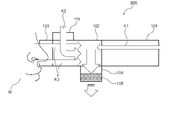
- FIG. 3 is a schematic configuration diagram showing a configuration example of the scent providing device 200. As shown in FIG. The scent providing device 200 is different from the scent providing device 100 according to the first embodiment in that it includes an intake section for sucking external airflow.
- the scent providing device 200 includes, for example, an aromatic portion 101, a space portion 102 connected to the aromatic portion 101, an emitting portion 103 connected to the space portion 102, and attached to the space portion 102. and a fragrant component trapping section 105 attached to the lower portion of the exhaust portion 104 in the exhaust direction. Furthermore, the scent providing device 200 includes an intake section 111 attached to the space section 102 .
- the intake section 111 is attached, for example, to the upper part of the space section 102 on the discharge section 103 side, and has an intake fan inside.
- the intake section 111 intakes the external airflow K3 into the space section 102 in conjunction with the exhaust section 104 .
- the fragrance operation is finished and the airflow discharge is turned off, and at the same time, the exhaust fan of the exhaust section 104 and the intake fan of the intake section 111 are turned on.
- the scent-containing airflow K1 staying on the side of the aromatic part 101 and the scent-containing airflow K2 staying on the side of the releasing part 103 pass through the space 102 and enter the space. It is sucked into an exhaust 104 attached to the bottom of 102 . At this time, the residual fragrance component F1 remaining in the space 102 is also sucked into the exhaust section 104 .
- the external airflow K3 sucked in the air intake portion 111 also passes through the space portion 102, and contains the residual scent component F1 retained in the space portion 102, and enters the exhaust portion 104 attached to the lower portion of the space portion 102. sucked in.
- the scent-containing airflow K1 containing the residual scent component F1, the scent-containing airflow K2, and the external airflow K3 sucked into the exhaust unit 104 are sent to the scent component capture unit 105, where they are After the scent component is captured and deodorized, it is released to the outside.
- FIG. 4 is a flow chart showing an operation example of a plurality of scent providing devices 100. As shown in FIG. 4
- step S101 the fragrance-containing airflow formed by the fragrance section 101 passes through the space section 102 and is emitted from the release section 103 to provide the user M with fragrance (perfume).
- step S102 by turning off the discharge of the airflow, the fragrance operation by emitting the scent-containing airflow is stopped, and the provision of the scent to the user M is finished.
- step S103 the exhaust fan of the exhaust unit 104 is turned on in conjunction with the end of the fragrance operation.
- step S104 the deodorizing filter 141 turns on deodorizing scanning of the space 102, and performs deodorizing processing within the space 102.
- step S ⁇ b>105 the intake fan of the intake section 111 is turned ON in conjunction with turning on the exhaust fan of the exhaust section 104 to suck the external airflow K ⁇ b>3 from the intake section 111 into the space section 102 .
- step S106 it is determined whether or not there is a fragrance instruction from another scent providing device 100 other than the scent providing device 100 that is performing the deodorizing process. If Yes, go to step S108. If No, the process proceeds to step S107 to continue the deodorizing process.
- step S108 after the deodorizing process in the space 102 has been sufficiently performed, the deodorizing scan of the space 102 is turned off.
- step S109 the intake fan of the intake unit 111 is turned off.
- step S110 the exhaust fan of the exhaust unit 104 is turned off.
- step S111 the deodorizing process ends. After the deodorizing process is completed, the process returns to step S101 to start the deodorizing process.
- the fragrance providing device 200 in addition to the same effect as the fragrance providing device 100 according to the first embodiment, since the external airflow K3 is also sucked in to deodorize, more unnecessary fragrance components are produced. can be properly removed.
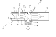
- FIG. 5 is a schematic configuration diagram showing a configuration example of the scent providing device 300. As shown in FIG. The scent providing device 300 is different from the scent providing device 200 according to the second embodiment in that it includes a plurality of intake units for sucking external airflow.
- the scent providing device 300 includes, for example, an aromatic portion 101, a space portion 102 connected to the aromatic portion 101, an emitting portion 103 connected to the space portion 102, and an air conditioner attached to the space portion 102. and a fragrant component trapping section 105 attached to the lower portion of the exhaust portion 104 in the exhaust direction.
- the fragrance section 101 has one or more perfume cartridges 114 holding perfume.
- the scent providing device 200 includes an intake section 111 and an intake section 112 attached to the space section 102 .
- the intake section 111 is attached, for example, to the upper part of the space section 102 on the discharge section 103 side, and has an intake fan inside.
- the intake section 111 intakes the external airflow K3 into the space section 102 in conjunction with the exhaust section 104 .
- the intake section 112 is attached, for example, to the upper portion of the space section 102 on the aromatic section 101 side, and has an intake fan inside. Intake portion 112 sucks external airflow K4 into space portion 102 in conjunction with intake portion 111 and exhaust portion 104 . Further, the intake section 112 has a flap 113 near its intake port, which is a rectifying mechanism that blows the external airflow K4 that has been taken in toward the discharge port of the fragrance cartridge 114 that discharges the fragrance-containing airflow of the fragrance section 101 . The flap 113 directs the external airflow K4 sucked from the suction part 112 to the outlet of the fragrance cartridge 114 to remove residual fragrance components adhering thereto.
- the fragrance operation is finished and the airflow discharge is turned off, and at the same time, the exhaust fan of the exhaust section 104 and the intake fan of the intake section 111 are turned on.
- the scent-containing airflow K1 staying on the side of the aromatic part 101 and the scent-containing airflow K2 staying on the side of the releasing part 103 pass through the space 102 and enter the space. It is sucked into an exhaust 104 attached to the bottom of 102 . At this time, the residual fragrance component F1 remaining in the space 102 is also sucked into the exhaust section 104 .
- the external airflow K3 sucked in the air intake portion 111 also passes through the space portion 102, and contains the residual scent component F1 retained in the space portion 102, and enters the exhaust portion 104 attached to the lower portion of the space portion 102. sucked in.
- the external airflow K4 taken in by the intake part 112 passes through the outlet of the fragrance cartridge 114 by means of the flap 113, and is attached to the lower part of the space part 102, including the residual fragrance component F1 adhering to the outlet. It is sucked into the exhaust section 104 .
- the scent-containing airflow K1 containing the residual scent component F1, the scent-containing airflow K2, the external airflow K3, and the external airflow K4, which are sucked into the exhaust unit 104, are sent to the scent component capture unit 105, where the scent component is extracted. After the scent component is captured by the capture unit 105 and deodorized, it is released to the outside.
- the external airflow K4 also sucks in and deodorizes residual fragrance components at the outlet of the fragrance cartridge 114. Therefore, more unnecessary fragrance components can be removed appropriately.
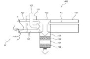
- FIG. 6 is a schematic configuration diagram showing a configuration example of the scent providing device 400. As shown in FIG. The scent providing device 400 differs from the scent providing device 200 according to the second embodiment in that it includes a plurality of exhaust units and scent component capturing units.
- the scent providing device 400 includes, for example, an aromatic portion 101, a space portion 102 connected to the aromatic portion 101, an emitting portion 103 connected to the space portion 102, and attached to the space portion 102. and a fragrant component trapping section 105 attached to the lower portion of the exhaust portion 104 in the exhaust direction.
- the scent providing device 400 also includes an intake section 111 attached to the upper portion of the space section 102 on the release section 103 side.
- the scent providing device 400 includes an exhaust section 121 attached in the lower exhaust direction of the fragrance component capturing section 105 and a fragrance component capturing section 122 attached in the lower exhaust direction of the exhaust section 121 .
- the exhaust section 121 and the scent component trapping section 122 have the same functions as the exhaust section 104 and the scent component trapping section 105, respectively.
- the number of exhaust units and scent component trapping units is not limited to that of the present embodiment, and any number may be attached according to the application.
- the fragrance operation is terminated and the discharge of the airflow is turned off, and at the same time, the exhaust fan of the exhaust section 104 and the intake fan of the intake section 111 are turned on.
- the scent-containing airflow K1 staying on the side of the aromatic part 101 and the scent-containing airflow K2 staying on the side of the releasing part 103 pass through the space 102 and enter the space. It is sucked into an exhaust 104 attached to the bottom of 102 . At this time, the residual fragrance component F1 remaining in the space 102 is also sucked into the exhaust section 104 .
- the external airflow K3 sucked in the air intake portion 111 also passes through the space portion 102, and contains the residual scent component F1 retained in the space portion 102, and enters the exhaust portion 104 attached to the lower portion of the space portion 102. sucked in.
- the scent-containing airflow K1 containing the residual scent component F1, the scent-containing airflow K2, and the external airflow K3 sucked into the exhaust unit 104 are sent to the scent component capture unit 105, where they are The fragrant component is captured and sucked into the exhaust section 121 .
- the scent-containing airflow K1, the scent-containing airflow K2, and the external airflow K3 sucked into the exhaust unit 121 are sent to the scent component capturing unit 122, where the scent component capturing unit 122 further extracts the scent components. After being captured and deodorized, it is released to the outside.
- the scent component is captured by the scent component capture unit 105 in the airflow. Since the part 122 further captures the fragrance component and then releases it to the outside, the accuracy of capturing the scent component increases, and the deodorizing effect can be enhanced.
- FIG. 7 is a schematic configuration diagram showing a configuration example of the scent providing device 500.
- the scent providing device 500 is different from the scent providing device 200 according to the second embodiment in that an intake section that draws in external airflow and an exhaust section that discharges the airflow to the outside are provided on the same straight line in the vertical direction.
- the scent providing device 500 includes, for example, an aromatic portion 101, a space portion 102 connected to the aromatic portion 101, an emitting portion 103 connected to the space portion 102, and an air conditioner attached to the space portion 102. and a fragrant component trapping section 105 attached to the lower portion of the exhaust portion 104 in the exhaust direction. Furthermore, the scent providing device 500 includes an intake section 131 attached to the space section 102 .
- the intake section 131 is attached, for example, to the upper part of the center in the left-right direction of the space section 102, and has an intake fan inside.
- the exhaust portion 104 is also attached to the lower portion of the center of the space portion 102 in the left-right direction, and the intake portion 131 and the exhaust portion 104 are arranged on the same straight line in the vertical direction.
- the intake section 111 intakes the external airflow K5 into the space section 102 in conjunction with the exhaust section 104 .
- the fragrance operation is terminated and the discharge of the airflow is turned off, and at the same time, the exhaust fan of the exhaust section 104 and the intake fan of the intake section 131 are turned on.
- the scent-containing airflow K1 staying on the side of the aromatic part 101 and the scent-containing airflow K2 staying on the side of the releasing part 103 pass through the space 102 and enter the space. It is sucked into an exhaust 104 attached to the bottom of 102 . At this time, the residual fragrance component F1 remaining in the space 102 is also sucked into the exhaust section 104 .
- the external airflow K5 sucked by the air intake portion 131 also passes through the space portion 102, and contains the residual scent component F1 remaining in the space portion 102, and enters the exhaust portion 104 attached to the lower portion of the space portion 102. sucked in.
- the intake portion 131 and the exhaust portion 104 are arranged on the same straight line in the vertical direction, the external airflow K5 taken in by the intake portion 131 does not stay in the space portion 102 while containing the residual scent component F1. It is sucked into the exhaust part 104 without any pressure.
- the scent-containing airflow K1 containing the residual scent component F1, the scent-containing airflow K2, and the external airflow K5 sucked into the exhaust unit 104 are sent to the scent component capture unit 105, where they are After the scent component is captured and deodorized, it is released to the outside.
- the intake part 131 and the exhaust part 104 are arranged on the same straight line in the vertical direction. Therefore, the lingering fragrance component F1 can be efficiently discharged to the exhaust portion 104 by the sucked external airflow K5, and the deodorizing effect can be enhanced.
- FIG. 8 is a schematic configuration diagram showing a configuration example of the scent providing device 600. As shown in FIG. The scent providing device 600 differs from the scent providing device 200 according to the second embodiment in that it does not include the release section 103 .
- the scent providing device 600 includes, for example, an aromatic portion 101, a space portion 102 connected to the aromatic portion 101, an exhaust portion 104 attached to the space portion 102, and a lower exhaust portion of the exhaust portion 104. and a fragrance component capturing part 105 attached in the direction. Furthermore, the scent providing device 200 includes an intake section 111 attached to the space section 102 .
- the scent providing device 600 passes the scent-containing airflow K1 discharged from the fragrance portion 101 through the space portion 102 and directly discharges it from the space portion 102 to the user M in the scent operation of providing the user M with scent.
- the deodorizing operation of the scent providing device 600 is the same as that of the scent providing device 200 according to the second embodiment, so the description is omitted.
- the scent providing device 600 in addition to the same effect as the scent providing device 200 according to the second embodiment, since it does not include the release unit 103 that releases the scent-containing airflow to the user M, It is possible to simplify, reduce the size and weight.
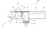
- FIG. 9 is a schematic configuration diagram showing a configuration example of the scent providing device 600. As shown in FIG. The scent providing device 700 differs from the scent providing device 200 according to the second embodiment in that a deodorizing filter is provided inside the space 102 .
- the scent providing device 700 includes, for example, an aromatic portion 101, a space portion 102 connected to the aromatic portion 101, an emitting portion 103 connected to the space portion 102, and an air conditioner attached to the space portion 102. and a fragrant component trapping section 105 attached to the lower portion of the exhaust portion 104 in the exhaust direction.
- the scent providing device 700 also includes an intake section 111 attached to the upper portion of the space section 102 on the release section 103 side.
- the scent providing device 700 includes a deodorizing filter 141 that adsorbs scent components staying in the space 102 .
- the scent providing device 700 can also include a scanning unit that scans the deodorizing filter 141 within the space 102 .
- the deodorizing filter 141 is arranged at the bottom of the space 102 and is vertically movable in the space 102 .
- the operation of the deodorizing filter 141 may be a horizontal operation, a rotating operation, or the like.
- the power source of the deodorizing filter 141 may be an actuator or airflow.
- a slit structure in which a gas-adsorbing substance such as activated carbon is woven or kneaded, or the fiber or structure itself has a gas-adsorbing structure, or the like can be applied.
- This slit structure may be a linear slit, or may be a honeycomb structure or the like.
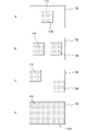
- FIG. 10A to 10D are schematic plan views showing configuration examples of deodorizing filters applicable to the scent providing device 700.
- FIG. 10A to 10D are schematic plan views showing configuration examples of deodorizing filters applicable to the scent providing device 700.
- the deodorizing filter 141 can use a linear slit structure arranged at regular intervals.
- the deodorizing filter 142 may have a slit structure in which a plurality of triangular shapes are arranged.
- the deodorizing filter 143 can use a slit structure in which a plurality of rectangles are arranged by arranging a plurality of orthogonal straight lines at regular intervals.
- the deodorizing filter 143 may have a slit structure with a honeycomb structure.
- FIGS. 9 and 11 to 13 are schematic configuration diagrams showing an operation example of the scent providing device 700.
- FIG. 11 to 13 are schematic configuration diagrams showing an operation example of the scent providing device 700.
- the fragrance operation is finished and the airflow discharge is turned off, and at the same time, the exhaust fan of the exhaust section 104 and the intake fan of the intake section 111 are turned on.
- the scent-containing airflow K1 staying on the side of the aromatic part 101 and the scent-containing airflow K2 staying on the side of the releasing part 103 pass through the space 102 and enter the space. It is sucked into an exhaust 104 attached to the bottom of 102 . At this time, the residual fragrance component F1 remaining in the space 102 is also sucked into the exhaust section 104 .
- the external airflow K3 sucked in the air intake portion 111 also passes through the space portion 102, and contains the residual scent component F1 retained in the space portion 102, and enters the exhaust portion 104 attached to the lower portion of the space portion 102. sucked in.
- the deodorizing filter 141 arranged at the bottom of the space 102 is moved upward in the moving direction D1 of the space 102 .
- the deodorizing filter 141 moves in the movement direction D1 to the ceiling in the space 102.
- the moving direction is reversed so that the deodorizing filter 141 moves downward in the moving direction D2 of the space 102. move.
- the deodorizing filter 141 moves in the movement direction D2 to the bottom of the space 102, as shown in FIG.
- the deodorizing filter 141 adsorbs and removes the scent components remaining in the space 102 .
- the scent-containing airflow K1 containing the residual scent component F1, the scent-containing airflow K2, and the external airflow K3 sucked into the exhaust unit 104 are sent to the scent component capturing unit 105, where they are After the scent component is captured and deodorized, it is released to the outside.
- the deodorizing filter 141 removes the scent components remaining in the space 102. Therefore, the deodorizing effect in the space 102 can be enhanced.
- FIG. 14 is a schematic configuration diagram showing a configuration example of the scent providing device 800. As shown in FIG. The scent providing device 800 differs from the scent providing device 200 according to the second embodiment in that a stirring mechanism is provided inside the space 102 .
- the scent providing device 800 includes, as an example, an aromatic portion 101, a space portion 102 connected to the aromatic portion 101, an emitting portion 103 connected to the space portion 102, and an air conditioner attached to the space portion 102. and a fragrant component trapping section 105 attached to the lower portion of the exhaust portion 104 in the exhaust direction.
- the scent providing device 800 also includes an intake section 111 attached to the upper portion of the space section 102 on the release section 103 side.
- the scent providing device 800 includes a deodorizing fan 151 that is a stirring mechanism that stirs and adsorbs the scent components staying in the space 102 .
- FIG. 15 is a schematic plan view showing a configuration example of the deodorizing fan 151 applicable to the scent providing device 800. As shown in FIG. 15
- the deodorizing fan 151 has a rotating shaft 152 and a plurality of rotating blades 153 attached to the rotating shaft 152 .
- the deodorizing fan 151 rotates a plurality of rotor blades 153 around a rotating shaft 152 counterclockwise toward the paper surface of FIG. 15 .
- the fragrance operation is terminated and the discharge of the airflow is turned off, and at the same time, the exhaust fan of the exhaust section 104 and the intake fan of the intake section 111 are turned on.
- the scent-containing airflow K1 staying on the side of the aromatic part 101 and the scent-containing airflow K2 staying on the side of the releasing part 103 pass through the space 102 and enter the space. It is sucked into an exhaust 104 attached to the bottom of 102 . At this time, the residual fragrance component F1 remaining in the space 102 is also sucked into the exhaust section 104 .
- the external airflow K3 sucked in the air intake portion 111 also passes through the space portion 102, and contains the residual scent component F1 retained in the space portion 102, and enters the exhaust portion 104 attached to the lower portion of the space portion 102. sucked in.
- the rotation operation of the deodorizing fan 151 arranged in the space 102 is started.
- the deodorizing fan 151 agitates, adsorbs, and removes the scent components remaining in the space 102 .
- the scent-containing airflow K1 containing the residual scent component F1, the scent-containing airflow K2, and the external airflow K3 sucked into the exhaust unit 104 are sent to the scent component capturing unit 105, where they are After the scent component is captured and deodorized, it is released to the outside.
- the deodorizing fan 151 removes the fragrance components remaining in the space 102. Therefore, the deodorizing effect in the space 102 can be enhanced.
- FIG. 16 is a schematic configuration diagram showing a configuration example of the scent providing device 900. As shown in FIG. The scent providing device 900 differs from the scent providing device 200 according to the second embodiment in that the inner wall surface of the device is provided with a deodorizing sheet.
- the scent providing device 900 includes, for example, a fragrance portion 101, a space portion 102 connected to the fragrance portion 101, a release portion 103 connected to the space portion 102, and attached to the space portion 102. and a fragrant component trapping section 105 attached to the lower portion of the exhaust portion 104 in the exhaust direction.
- the scent providing device 900 also includes an intake section 111 attached to the upper portion of the space section 102 on the release section 103 side.
- the scent providing device 900 includes deodorizing sheets 161 and 162 that cover the inner wall surfaces of the aromatic portion 101 and/or the space portion 102 and are detachable.
- the deodorizing sheet 161 covers the upper inner wall surface of the space portion 102 .
- the deodorizing sheet 162 covers the upper inner wall surface of the space 102 .
- the deodorizing sheet 161 and the deodorizing sheet 162 adsorb and remove the scent components remaining in the space 102 .
- the deodorizing sheet 161 and the deodorizing sheet 162 can also cover the upper and lower inner wall surfaces of the discharge section 103 .
- the fragrance operation is terminated and the airflow discharge is turned off, and at the same time, the exhaust fan of the exhaust section 104 and the intake fan of the intake section 111 are turned on.
- the scent-containing airflow K1 staying on the side of the aromatic part 101 and the scent-containing airflow K2 staying on the side of the releasing part 103 pass through the space 102 and enter the space. It is sucked into an exhaust 104 attached to the bottom of 102 . At this time, the residual fragrance component F1 remaining in the space 102 is also sucked into the exhaust section 104 .
- the external airflow K3 sucked in the air intake portion 111 also passes through the space portion 102, and contains the residual scent component F1 retained in the space portion 102, and enters the exhaust portion 104 attached to the lower portion of the space portion 102. sucked in.
- the deodorizing sheet 161 and the deodorizing sheet 162 absorb and remove the scent components remaining in the aromatic portion 101, the space portion 102, and the release portion 103. Note that this step can be performed concurrently with other steps.
- the scent-containing airflow K1 containing the residual scent component F1, the scent-containing airflow K2, and the external airflow K3 sucked into the exhaust unit 104 are sent to the scent component capturing unit 105, where they are After the scent component is captured and deodorized, it is released to the outside.
- the scent providing device 900 in addition to the same effect as the scent providing device 200 according to the second embodiment, the scent components remaining in the space 102 are removed by the deodorizing sheets 161 and 162. Since it is removed, the deodorizing effect in the space part 102 can be enhanced.
- FIG. 17 is a schematic configuration diagram showing a configuration example of the scent providing device 1000.
- the scent providing device 1000 differs from the scent providing device 100 according to the first embodiment in that it has a structure in which droplets of the user M do not flow into the scent providing device 1000 .
- the scent providing device 1000 includes, as an example, a fragrance portion 101, a space portion 102 connected to the fragrance portion 101, a release portion 103 connected to the space portion 102, and attached to the space portion 102. and a fragrant component trapping section 105 attached to the lower portion of the exhaust portion 104 in the exhaust direction.
- the scent providing device 1000 has a structure in which the emitting part 103 has a nose cover, and the nose cover is worn on the user M's nose. Further, a slope-shaped structure 171 inclined toward the user M is provided inside the nose cover. Note that the structure 171 may be a bent portion.
- the structure 171 has a slope shape that inclines toward the user M side, even if the droplets of the user M flow into the discharge portion 103, the slope shape reflects the droplets toward the user M side, and the space portion It is possible to prevent droplets from flowing into 102 and the aromatic portion 101 and the like.
- the scent providing device 1000 performs the same operations as the scent providing device 100 according to the first embodiment for the scenting operation of providing the scent to the user M and the deodorizing operation of the space part 102, so description thereof will be omitted. do.
- the structure 171 can prevent droplets from flowing into the scent providing device 1000. can.
- FIG. 18 is a schematic configuration diagram showing a configuration example of the scent providing device 1100. As shown in FIG. The scent providing device 1100 differs from the scent providing device 200 according to the second embodiment in that it has a function of preventing the droplets of the user M from flowing into the scent providing device 1000 .
- the scent providing device 1100 includes, for example, an aromatic portion 101, a space portion 102 connected to the aromatic portion 101, an emitting portion 103 connected to the space portion 102, and attached to the space portion 102. and a fragrant component trapping section 105 attached to the lower portion of the exhaust portion 104 in the exhaust direction.
- the scent providing device 1100 also includes an intake section 181 attached to the upper portion of the space section 102 on the release section 103 side.
- the intake unit 181 has, for example, an intake fan inside.
- the intake section 181 works in conjunction with the exhaust section 104 to intake the external airflow K12 into the space section 102 .
- the intake unit 181 directs the external airflow K12 toward the nose tip of the user M to generate an airflow.
- the air shutter is generated by the external airflow K12, so that the droplets can be prevented from flowing into the space portion 102, the fragrance portion 101, and the like. can.
- the intake section 181 and/or the exhaust section 104 constantly blows the external airflow K12 sucked from the intake section 181 to the discharge section 103, and at the time of exhaustion, the airflow in the space section 102 is exhausted from the exhaust section 104 to the outside.
- a control unit 182 for controlling the can be provided.
- the scent providing device 1100 can be provided with a sensor 183 such as a pressure sensor that detects the airflow flowing in the direction of the space portion 102 from the emitting portion 103, such as the backflow of scent-containing airflow toward the user M or the inflow of droplets.
- a sensor 183 such as a pressure sensor that detects the airflow flowing in the direction of the space portion 102 from the emitting portion 103, such as the backflow of scent-containing airflow toward the user M or the inflow of droplets.
- the scent providing device 1100 can detect a backflow or an inflowing airflow, operate the external airflow K12 as an air shutter, and discharge a scent-containing airflow from the fragrance section 101 when detecting a backflow or an inflowing airflow. can also be stopped.
- FIGS. 19A to 19D are schematic plan views showing arrangement examples of the intake section 111 and the exhaust section 104 of the space section 102 viewed from above the scent providing device 1100.
- FIG. 19 It should be noted that any of the arrangement examples of FIGS. 19A to 19D can be combined.
- the intake section 111 and the exhaust section 104 can be arranged on the same straight line in the vertical direction by completely overlapping near the center of the space section 102 in plan view.
- the intake portion 111 can be arranged on the left side of the space portion 102 on the side of the discharge portion 103 in plan view
- the exhaust portion 104 can be arranged on the right side of the space portion 102 on the side of the aromatic portion 101 in plan view. can.
- the intake part 111 can be arranged at the upper left corner of the space part 102 in plan view, and the exhaust part 104 can be arranged at the lower right corner of the space part 102 in plan view.
- the intake section 111 can be arranged over the entire upper surface of the space section 102 and the exhaust section 104 can be arranged over the entire lower surface of the space section 102 .
- the scent providing device 1100 performs both the scenting operation of providing the scent to the user M and the operation of deodorizing the space 102 in the same manner as the scent providing device 200 according to the second embodiment, the description will be omitted. omitted.
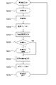
- FIG. 20 is a flow chart showing an operation example of the multiple scent providing devices 1100 .
- step S201 the air intake unit 181 is always turned on to generate an external airflow K12 toward the user M at all times.
- step S202 the scent-containing airflow K11 formed in the fragrance section 101 passes through the space section 102 and is emitted from the release section 103 to start providing the user M with fragrance (fragrance).
- step S203 by turning off the discharge of the airflow, the fragrance operation by emitting the scent-containing airflow K11 is stopped, and the provision of the scent to the user M is finished.
- step S204 the exhaust fan of the exhaust unit 104 is turned on in conjunction with the end of the fragrance operation.
- step S205 the deodorizing filter 141 turns on deodorizing scanning of the space 102, and performs deodorizing processing within the space 102.
- step S206 it is determined whether or not there is a fragrance instruction from another scent providing device 1100 other than the scent providing device 1100 that is performing the deodorizing process. If Yes, go to step S208. If No, the process proceeds to step S207 to continue the deodorizing process.
- step S208 after the deodorizing process in the space 102 has been sufficiently performed, the deodorizing scan of the space 102 is turned off.
- step S209 the exhaust fan of the exhaust unit 104 is turned off.
- step S210 the deodorizing process ends. After the deodorizing process ends, the process returns to step S201 to start the deodorizing process.
- the external airflow K12 in the direction of the user M generated by the intake unit 181 causes the inside of the scent providing device 1100 to It is possible to prevent the inflow of droplets into the
- the scent providing device according to this technology can be used, for example, in an olfactory display that artificially presents scents along with images. Furthermore, the scent providing device according to the present technology can also be used in an inspection device for measuring olfactory ability.
- FIG. 21 is a schematic configuration diagram showing a configuration example of the scent providing device 1200.
- the scent providing device 1200 is different from the scent providing device 100 according to the first embodiment in that an intake fan for sucking an external airflow is provided in the fragrance section 101 and a plurality of scent cartridges 114 are arranged in a fan shape.
- the scent providing device 1200 includes, as an example, a fragrance portion 101, a space portion 102 connected to the fragrance portion 101, a release portion 103 connected to the space portion 102, and attached to the space portion 102. and a fragrant component trapping section 105 attached to the lower portion of the exhaust portion 104 in the exhaust direction.
- the fragrance section 101 has an intake fan 191 that generates a main airflow that travels straight toward the nose of the user M via the space section 102 and the discharge section 103 .
- a plurality of fragrance cartridges 114 are arranged in a fan shape on the side of the space 102 in front of the intake fan 191 so as to discharge fragrance components toward the main airflow emitted from the intake fan 191 .
- the fragrance section 101 has a pump 192 that pumps air into the plurality of fragrance cartridges 114 .
- the air containing the fragrance component discharged from the fragrance cartridge 114 is discharged toward the main air current and sent to the nose of the user M on the main air current.
- the main airflow generated from the intake fan 191 does not have to travel straight, and the plurality of perfume cartridges 114 may be arranged in a spherical shape or the like.
- FIG. FIG. 22 is a schematic configuration diagram showing an operation example of the scent providing device 1200. As shown in FIG.
- the fragrance operation of the fragrance providing device 1200 is as follows: in the first step, the fragrance of the fragrance to be provided to the user M is held in the fragrance holding body; Incorporate into 101.
- the discharge of the main airflow generated by the intake fan 191 is turned on all the time to flow the airflow into the fragrance section 101 .
- the ventilation of the pump 192 is turned on to send air to the plurality of fragrance cartridges 114 .
- the fragrant component F2 is discharged from the plurality of perfume cartridges 114 toward the main airflow.
- a scent-containing airflow K21 containing a scent is formed by contacting the scent component F2 with the main airflow flowed into the fragrance portion 101 .
- the formed scent-containing airflow K21 is sent to the user M's nose.
- the operation of the deodorizing process of the fragrance providing device 1200 is the first step, in which the fragrance operation is finished, the suction supply of the pump 192 is turned off, and the exhaust fan of the exhaust unit 104 is turned on.
- the scent providing device 1200 can also perform an operation to increase the intake air volume by increasing the number of revolutions of the intake fan 191 as the exhaust fan of the exhaust unit 104 is turned on.
- the scent-containing airflow K21 staying on the side of the aromatic part 101 and the scent-containing airflow K22 staying on the side of the releasing part 103 pass through the space 102 and move to the lower part of the space 102. is sucked into the exhaust 104 attached to the At this time, the residual fragrance component F1 remaining in the space 102 is also sucked into the exhaust section 104 .
- the scent-containing airflow K21 and the scent-containing airflow K22 containing the residual scent component F1 sucked into the exhaust unit 104 are sent to the scent component capturing unit 105, and the scent components are captured by the scent component capturing unit 105. After being deodorized, it is released to the outside.
- fragrance providing device 1200 in addition to the same effect as the fragrance providing device 100 according to the first embodiment, air containing fragrance components in the main airflow generated from the intake fan 191 during the fragrance operation. is sent to the nose of the user M, it is possible to reduce the retention of residual scent in the fragrance portion 101, the space portion 102, and the release portion 103, and the adhesion of scent components to the inner wall surfaces of these structures. .
- the present technology can have the following configuration.
- an aromatic unit that discharges a fragrance-containing airflow containing fragrance; a space portion for passing or retaining the scent-containing airflow discharged from the aromatic portion; a release unit configured to release the scent-containing airflow that has passed through the space to a user; an exhaust unit that exhausts the scent-containing airflow that has accumulated in the space to the outside; a scent component trapping section for trapping volatile components in the scent-containing airflow discharged by the exhaust section;
- a scent providing device comprising: (2) The scent providing device according to (1), wherein the exhaust unit performs an operation of exhausting in conjunction with an operation of releasing the scent-containing airflow.
- the scent providing device has a guide portion that guides the scent-containing airflow toward the fragrance portion and/or the tip of the nose of the user.
- the fragrance providing device has a plurality of fragrance holding members holding fragrance.
- the release section has a detachable nose cover.
- the scent providing device is formed in a structure to be attached to the user's nose, and has a slope or bent portion inside the nose cover that slopes toward the user.
- the scent providing device according to any one of (1) to (6), further comprising an intake section that is linked to the exhaust section and sucks external airflow into the space section.
- the intake section has a rectifying mechanism that blows the external airflow that has been taken in toward an outlet of the fragrance section that discharges the scent-containing airflow.
- the deodorizing filter that adsorbs the volatile components remaining in the space, and a scanning unit that scans the deodorizing filter within the space. scent providing device.
- the scent providing device according to any one of (1) to (9), further comprising a stirring mechanism that stirs and adsorbs the volatile components staying in the space.
- the scent providing device according to any one of (1) to (10), further comprising a detachable deodorizing sheet covering the inner wall surface of the aromatic portion and/or the space portion. (12) (7) further comprising a control unit for controlling an operation of constantly blowing the external airflow sucked from the intake unit to the discharge unit, and discharging the airflow in the space to the outside from the exhaust unit during exhaustion; The scent providing device according to any one of (11) to (11). (13) (1) to (12), further comprising a sensor for detecting an airflow flowing from the discharge portion toward the space, wherein the fragrance portion stops discharging the scent-containing airflow when the inflowing airflow is detected.
- the scent providing device according to any one of the above.
Landscapes
- Health & Medical Sciences (AREA)
- Epidemiology (AREA)
- Life Sciences & Earth Sciences (AREA)
- Animal Behavior & Ethology (AREA)
- General Health & Medical Sciences (AREA)
- Public Health (AREA)
- Veterinary Medicine (AREA)
- Disinfection, Sterilisation Or Deodorisation Of Air (AREA)
Priority Applications (3)
| Application Number | Priority Date | Filing Date | Title |
|---|---|---|---|
| US18/283,072 US20240148928A1 (en) | 2021-03-30 | 2022-02-18 | Scent dispensing device and scent removing method |
| JP2023510640A JPWO2022209405A1 (https=) | 2021-03-30 | 2022-02-18 | |
| CN202280018060.9A CN117015405A (zh) | 2021-03-30 | 2022-02-18 | 香味提供装置和香味去除方法 |
Applications Claiming Priority (2)
| Application Number | Priority Date | Filing Date | Title |
|---|---|---|---|
| JP2021057196 | 2021-03-30 | ||
| JP2021-057196 | 2021-03-30 |
Publications (1)
| Publication Number | Publication Date |
|---|---|
| WO2022209405A1 true WO2022209405A1 (ja) | 2022-10-06 |
Family
ID=83455985
Family Applications (1)
| Application Number | Title | Priority Date | Filing Date |
|---|---|---|---|
| PCT/JP2022/006604 Ceased WO2022209405A1 (ja) | 2021-03-30 | 2022-02-18 | 香り提供装置および香り脱臭方法 |
Country Status (4)
| Country | Link |
|---|---|
| US (1) | US20240148928A1 (https=) |
| JP (1) | JPWO2022209405A1 (https=) |
| CN (1) | CN117015405A (https=) |
| WO (1) | WO2022209405A1 (https=) |
Citations (8)
| Publication number | Priority date | Publication date | Assignee | Title |
|---|---|---|---|---|
| JPH09173431A (ja) * | 1995-12-22 | 1997-07-08 | Pioneer Electron Corp | 芳香散布装置 |
| JP2002085542A (ja) * | 2000-09-18 | 2002-03-26 | Kao Corp | 芳香成分の放散装置 |
| JP2002537961A (ja) * | 1999-03-12 | 2002-11-12 | マイクロセント, エルエルシー. | 芳香エアゾールの局所送達のための方法および装置 |
| JP2005304608A (ja) * | 2004-04-19 | 2005-11-04 | Seiko Epson Corp | 香気装置 |
| JP2014219644A (ja) * | 2013-05-11 | 2014-11-20 | 純馬 青木 | 匂い呈示装置および方法 |
| JP2016129577A (ja) * | 2015-01-14 | 2016-07-21 | 株式会社島津製作所 | 嗅覚検査装置 |
| WO2016199441A1 (ja) * | 2015-06-12 | 2016-12-15 | 株式会社ソニー・インタラクティブエンタテインメント | 香料提示デバイス |
| JP2019048071A (ja) * | 2015-12-09 | 2019-03-28 | 株式会社ソニー・インタラクティブエンタテインメント | 匂い提示装置 |
Family Cites Families (2)
| Publication number | Priority date | Publication date | Assignee | Title |
|---|---|---|---|---|
| EP2114468A4 (en) * | 2006-11-21 | 2010-12-15 | David Sissom | INDEPENDENT PERFUME SAMPLE SYSTEM |
| CN203724574U (zh) * | 2012-09-18 | 2014-07-23 | 蒋准飞 | 便携式的空调及空气净化器一体化机 |
-
2022
- 2022-02-18 CN CN202280018060.9A patent/CN117015405A/zh active Pending
- 2022-02-18 US US18/283,072 patent/US20240148928A1/en active Pending
- 2022-02-18 WO PCT/JP2022/006604 patent/WO2022209405A1/ja not_active Ceased
- 2022-02-18 JP JP2023510640A patent/JPWO2022209405A1/ja active Pending
Patent Citations (8)
| Publication number | Priority date | Publication date | Assignee | Title |
|---|---|---|---|---|
| JPH09173431A (ja) * | 1995-12-22 | 1997-07-08 | Pioneer Electron Corp | 芳香散布装置 |
| JP2002537961A (ja) * | 1999-03-12 | 2002-11-12 | マイクロセント, エルエルシー. | 芳香エアゾールの局所送達のための方法および装置 |
| JP2002085542A (ja) * | 2000-09-18 | 2002-03-26 | Kao Corp | 芳香成分の放散装置 |
| JP2005304608A (ja) * | 2004-04-19 | 2005-11-04 | Seiko Epson Corp | 香気装置 |
| JP2014219644A (ja) * | 2013-05-11 | 2014-11-20 | 純馬 青木 | 匂い呈示装置および方法 |
| JP2016129577A (ja) * | 2015-01-14 | 2016-07-21 | 株式会社島津製作所 | 嗅覚検査装置 |
| WO2016199441A1 (ja) * | 2015-06-12 | 2016-12-15 | 株式会社ソニー・インタラクティブエンタテインメント | 香料提示デバイス |
| JP2019048071A (ja) * | 2015-12-09 | 2019-03-28 | 株式会社ソニー・インタラクティブエンタテインメント | 匂い提示装置 |
Also Published As
| Publication number | Publication date |
|---|---|
| JPWO2022209405A1 (https=) | 2022-10-06 |
| US20240148928A1 (en) | 2024-05-09 |
| CN117015405A (zh) | 2023-11-07 |
Similar Documents
| Publication | Publication Date | Title |
|---|---|---|
| JP6374638B2 (ja) | 汚染物質処理装置及びこれを用いた空気清浄維持システム | |
| JP6473910B2 (ja) | 除菌機能付き加湿空気清浄装置 | |
| KR102162454B1 (ko) | 음이온방출, 살균 및 방향휘산 다기능 차량용 공기청정기 | |
| WO1992009355A1 (en) | Method of treating air with discs in multilayer structure | |
| JP6367445B2 (ja) | 加湿空気清浄機 | |
| KR102464405B1 (ko) | 발향이 가능한 공기 청정기 | |
| JP5494340B2 (ja) | 加湿装置 | |
| WO2022209405A1 (ja) | 香り提供装置および香り脱臭方法 | |
| JP2009250463A (ja) | 空気清浄機 | |
| JP2020110436A (ja) | 脱臭工法及び脱臭施工システム | |
| JP2008215781A (ja) | 空気調和機 | |
| KR20100107986A (ko) | 공기 청정기 | |
| CN100591423C (zh) | 空气净化器 | |
| JP2008132156A (ja) | 電気掃除機 | |
| KR20190092779A (ko) | 습도 조절 기능을 갖는 미세먼지 공기청정기 | |
| JP2011143048A (ja) | 電気掃除機 | |
| JP3577443B2 (ja) | 室内脱臭機 | |
| JP2009039545A (ja) | 静電霧化装置 | |
| JP2004024414A (ja) | 電気掃除機 | |
| JP4668147B2 (ja) | 電気掃除機 | |
| JP2006250396A (ja) | 空気清浄機能付喫煙室 | |
| KR20210094218A (ko) | 방향제 겸용 차량용 공기청정기 | |
| JPH11351622A (ja) | 空気処理装置 | |
| JP2015123178A (ja) | 空気清浄機 | |
| KR20100025433A (ko) | 공기 청정기 |
Legal Events
| Date | Code | Title | Description |
|---|---|---|---|
| 121 | Ep: the epo has been informed by wipo that ep was designated in this application |
Ref document number: 22779632 Country of ref document: EP Kind code of ref document: A1 |
|
| WWE | Wipo information: entry into national phase |
Ref document number: 2023510640 Country of ref document: JP |
|
| WWE | Wipo information: entry into national phase |
Ref document number: 202280018060.9 Country of ref document: CN |
|
| WWE | Wipo information: entry into national phase |
Ref document number: 18283072 Country of ref document: US |
|
| NENP | Non-entry into the national phase |
Ref country code: DE |
|
| 122 | Ep: pct application non-entry in european phase |
Ref document number: 22779632 Country of ref document: EP Kind code of ref document: A1 |