WO2022209060A1 - 二次電池 - Google Patents
二次電池 Download PDFInfo
- Publication number
- WO2022209060A1 WO2022209060A1 PCT/JP2021/047214 JP2021047214W WO2022209060A1 WO 2022209060 A1 WO2022209060 A1 WO 2022209060A1 JP 2021047214 W JP2021047214 W JP 2021047214W WO 2022209060 A1 WO2022209060 A1 WO 2022209060A1
- Authority
- WO
- WIPO (PCT)
- Prior art keywords
- secondary battery
- positive electrode
- negative electrode
- lid portion
- lid
- Prior art date
- Legal status (The legal status is an assumption and is not a legal conclusion. Google has not performed a legal analysis and makes no representation as to the accuracy of the status listed.)
- Ceased
Links
Images




Classifications
-
- H—ELECTRICITY
- H01—ELECTRIC ELEMENTS
- H01M—PROCESSES OR MEANS, e.g. BATTERIES, FOR THE DIRECT CONVERSION OF CHEMICAL ENERGY INTO ELECTRICAL ENERGY
- H01M50/00—Constructional details or processes of manufacture of the non-active parts of electrochemical cells other than fuel cells, e.g. hybrid cells
- H01M50/10—Primary casings; Jackets or wrappings
- H01M50/147—Lids or covers
- H01M50/148—Lids or covers characterised by their shape
- H01M50/153—Lids or covers characterised by their shape for button or coin cells
-
- H—ELECTRICITY
- H01—ELECTRIC ELEMENTS
- H01M—PROCESSES OR MEANS, e.g. BATTERIES, FOR THE DIRECT CONVERSION OF CHEMICAL ENERGY INTO ELECTRICAL ENERGY
- H01M10/00—Secondary cells; Manufacture thereof
- H01M10/05—Accumulators with non-aqueous electrolyte
- H01M10/052—Li-accumulators
- H01M10/0525—Rocking-chair batteries, i.e. batteries with lithium insertion or intercalation in both electrodes; Lithium-ion batteries
-
- H—ELECTRICITY
- H01—ELECTRIC ELEMENTS
- H01M—PROCESSES OR MEANS, e.g. BATTERIES, FOR THE DIRECT CONVERSION OF CHEMICAL ENERGY INTO ELECTRICAL ENERGY
- H01M50/00—Constructional details or processes of manufacture of the non-active parts of electrochemical cells other than fuel cells, e.g. hybrid cells
- H01M50/10—Primary casings; Jackets or wrappings
- H01M50/102—Primary casings; Jackets or wrappings characterised by their shape or physical structure
- H01M50/103—Primary casings; Jackets or wrappings characterised by their shape or physical structure prismatic or rectangular
-
- H—ELECTRICITY
- H01—ELECTRIC ELEMENTS
- H01M—PROCESSES OR MEANS, e.g. BATTERIES, FOR THE DIRECT CONVERSION OF CHEMICAL ENERGY INTO ELECTRICAL ENERGY
- H01M50/00—Constructional details or processes of manufacture of the non-active parts of electrochemical cells other than fuel cells, e.g. hybrid cells
- H01M50/10—Primary casings; Jackets or wrappings
- H01M50/102—Primary casings; Jackets or wrappings characterised by their shape or physical structure
- H01M50/109—Primary casings; Jackets or wrappings characterised by their shape or physical structure of button or coin shape
-
- H—ELECTRICITY
- H01—ELECTRIC ELEMENTS
- H01M—PROCESSES OR MEANS, e.g. BATTERIES, FOR THE DIRECT CONVERSION OF CHEMICAL ENERGY INTO ELECTRICAL ENERGY
- H01M50/00—Constructional details or processes of manufacture of the non-active parts of electrochemical cells other than fuel cells, e.g. hybrid cells
- H01M50/10—Primary casings; Jackets or wrappings
- H01M50/172—Arrangements of electric connectors penetrating the casing
- H01M50/174—Arrangements of electric connectors penetrating the casing adapted for the shape of the cells
- H01M50/176—Arrangements of electric connectors penetrating the casing adapted for the shape of the cells for prismatic or rectangular cells
-
- H—ELECTRICITY
- H01—ELECTRIC ELEMENTS
- H01M—PROCESSES OR MEANS, e.g. BATTERIES, FOR THE DIRECT CONVERSION OF CHEMICAL ENERGY INTO ELECTRICAL ENERGY
- H01M50/00—Constructional details or processes of manufacture of the non-active parts of electrochemical cells other than fuel cells, e.g. hybrid cells
- H01M50/50—Current conducting connections for cells or batteries
- H01M50/543—Terminals
- H01M50/545—Terminals formed by the casing of the cells
-
- H—ELECTRICITY
- H01—ELECTRIC ELEMENTS
- H01M—PROCESSES OR MEANS, e.g. BATTERIES, FOR THE DIRECT CONVERSION OF CHEMICAL ENERGY INTO ELECTRICAL ENERGY
- H01M50/00—Constructional details or processes of manufacture of the non-active parts of electrochemical cells other than fuel cells, e.g. hybrid cells
- H01M50/50—Current conducting connections for cells or batteries
- H01M50/543—Terminals
- H01M50/547—Terminals characterised by the disposition of the terminals on the cells
-
- H—ELECTRICITY
- H01—ELECTRIC ELEMENTS
- H01M—PROCESSES OR MEANS, e.g. BATTERIES, FOR THE DIRECT CONVERSION OF CHEMICAL ENERGY INTO ELECTRICAL ENERGY
- H01M50/00—Constructional details or processes of manufacture of the non-active parts of electrochemical cells other than fuel cells, e.g. hybrid cells
- H01M50/50—Current conducting connections for cells or batteries
- H01M50/543—Terminals
- H01M50/547—Terminals characterised by the disposition of the terminals on the cells
- H01M50/55—Terminals characterised by the disposition of the terminals on the cells on the same side of the cell
-
- H—ELECTRICITY
- H01—ELECTRIC ELEMENTS
- H01M—PROCESSES OR MEANS, e.g. BATTERIES, FOR THE DIRECT CONVERSION OF CHEMICAL ENERGY INTO ELECTRICAL ENERGY
- H01M50/00—Constructional details or processes of manufacture of the non-active parts of electrochemical cells other than fuel cells, e.g. hybrid cells
- H01M50/50—Current conducting connections for cells or batteries
- H01M50/543—Terminals
- H01M50/552—Terminals characterised by their shape
- H01M50/553—Terminals adapted for prismatic, pouch or rectangular cells
-
- H—ELECTRICITY
- H01—ELECTRIC ELEMENTS
- H01M—PROCESSES OR MEANS, e.g. BATTERIES, FOR THE DIRECT CONVERSION OF CHEMICAL ENERGY INTO ELECTRICAL ENERGY
- H01M50/00—Constructional details or processes of manufacture of the non-active parts of electrochemical cells other than fuel cells, e.g. hybrid cells
- H01M50/50—Current conducting connections for cells or batteries
- H01M50/543—Terminals
- H01M50/552—Terminals characterised by their shape
- H01M50/559—Terminals adapted for cells having curved cross-section, e.g. round, elliptic or button cells
-
- H—ELECTRICITY
- H01—ELECTRIC ELEMENTS
- H01M—PROCESSES OR MEANS, e.g. BATTERIES, FOR THE DIRECT CONVERSION OF CHEMICAL ENERGY INTO ELECTRICAL ENERGY
- H01M50/00—Constructional details or processes of manufacture of the non-active parts of electrochemical cells other than fuel cells, e.g. hybrid cells
- H01M50/50—Current conducting connections for cells or batteries
- H01M50/543—Terminals
- H01M50/564—Terminals characterised by their manufacturing process
-
- Y—GENERAL TAGGING OF NEW TECHNOLOGICAL DEVELOPMENTS; GENERAL TAGGING OF CROSS-SECTIONAL TECHNOLOGIES SPANNING OVER SEVERAL SECTIONS OF THE IPC; TECHNICAL SUBJECTS COVERED BY FORMER USPC CROSS-REFERENCE ART COLLECTIONS [XRACs] AND DIGESTS
- Y02—TECHNOLOGIES OR APPLICATIONS FOR MITIGATION OR ADAPTATION AGAINST CLIMATE CHANGE
- Y02E—REDUCTION OF GREENHOUSE GAS [GHG] EMISSIONS, RELATED TO ENERGY GENERATION, TRANSMISSION OR DISTRIBUTION
- Y02E60/00—Enabling technologies; Technologies with a potential or indirect contribution to GHG emissions mitigation
- Y02E60/10—Energy storage using batteries
Definitions
- This technology relates to secondary batteries.
- secondary batteries Due to the widespread use of various electronic devices such as mobile phones, secondary batteries are being developed as power sources that are compact, lightweight, and capable of obtaining high energy density.
- This secondary battery has a battery element housed inside an exterior member, and various studies have been made on the configuration of the secondary battery.
- the power generation element is housed inside a rectangular housing member, the opening surface of the housing member is closed by a lid member, and the external terminal member is attached to the lid member.
- An external terminal member protrudes outward from the lid member (see, for example, Patent Document 1).
- An electrode body is housed inside a battery outer can, a sealing plate is fixed to an opening of the battery outer can, and an external terminal is attached to the sealing plate (see, for example, Patent Document 2). .
- An electrode assembly is housed inside a case body, and a lid body is joined to the opening edge of the case body, and the lid body has a thick portion (see, for example, Patent Document 3).
- a power generation element is housed inside a cylindrical outer can, and a sealing plate is arranged in the open end of the outer can, and the sealing plate has a thick portion (for example, Patent Document 4 reference.).
- a secondary battery includes an exterior member, a battery element housed inside the exterior member, electrode terminals disposed outside the exterior member, and the electrode terminals and the exterior member. and an insulating adhesive member disposed therebetween.
- the exterior member includes a storage portion having an opening for storing the battery element inside, and a lid portion that closes the opening and is joined to the storage portion. At least a part of the outer peripheral edge of the electrode terminal is adhered to the lid via an adhesive member, and the thickness of the electrode terminal is greater than the thickness of the lid.
- the battery element is housed inside the exterior member, the electrode terminal is arranged outside the exterior member, and the electrode terminal is disposed between the exterior member and the electrode terminal.
- An insulating adhesive member is arranged in the housing portion, and the exterior member includes a lid portion joined to the storage portion, and at least a part of the outer peripheral end portion of the electrode terminal is attached to the lid portion via the adhesive member. and the thickness of the electrode terminal is larger than the thickness of the lid portion, so excellent deformation resistance can be obtained.
- FIG. 2 is an enlarged cross-sectional view showing the configuration of the secondary battery shown in FIG. 1;
- FIG. 3 is a cross-sectional view showing an enlarged configuration of a part of the secondary battery shown in FIG. 2;
- FIG. 3 is an enlarged sectional view showing the configuration of the battery element shown in FIG. 2;
- FIG. 3 is a cross-sectional view showing an enlarged configuration of external terminals and auxiliary terminals shown in FIG. 2;
- FIG. FIG. 4 is a cross-sectional view for explaining a method of manufacturing a secondary battery;
- FIG. 2 is a cross-sectional view showing an enlarged configuration of a part of a secondary battery of a comparative example;
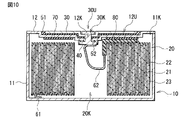
- 3 is a cross-sectional view for explaining problems of a secondary battery of a comparative example; 3 is a cross-sectional view showing the configuration of a secondary battery of Modification 1.
- FIG. 10 is a cross-sectional view showing the configuration of a secondary battery of Modification 2.
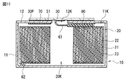
- FIG. 11 is a cross-sectional view showing the configuration of a secondary battery of Modification 3;
- the secondary battery described here has a columnar three-dimensional shape. As will be described later, this secondary battery has a pair of bottom portions facing each other and side wall portions connected to each of the pair of bottom portions.
- the secondary battery is a so-called coin-side or button-type secondary battery, and the height of the secondary battery is smaller than the outer diameter.
- the “outer diameter” is the diameter (maximum diameter) of each of the pair of bottoms, and the “height” is the distance (maximum distance) from one bottom to the other.
- This secondary battery includes an electrolyte together with a positive electrode and a negative electrode, and in the secondary battery, the charge capacity of the negative electrode is greater than the discharge capacity of the positive electrode. That is, the electrochemical capacity per unit area of the negative electrode is set to be larger than the electrochemical capacity per unit area of the positive electrode. This is to prevent electrode reactants from depositing on the surface of the negative electrode during charging.
- the type of electrode reactant is not particularly limited, but specifically light metals such as alkali metals and alkaline earth metals.
- alkali metals are lithium, sodium and potassium
- alkaline earth metals are beryllium, magnesium and calcium.
- lithium ion secondary battery A secondary battery whose battery capacity is obtained by utilizing the absorption and release of lithium is a so-called lithium ion secondary battery.
- lithium ion secondary battery lithium is intercalated and deintercalated in an ionic state.
- FIG. 1 shows a perspective configuration of a secondary battery.
- FIG. 2 is an enlarged sectional view of the secondary battery shown in FIG.
- FIG. 3 is an enlarged sectional view of part of the secondary battery shown in FIG.
- FIG. 4 is an enlarged sectional view of the battery element 20 shown in FIG.
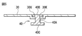
- FIG. 5 is an enlarged cross-sectional configuration of the external terminal 30 and the auxiliary terminal 40 shown in FIG.
- FIG. 3 only a part of each of the outer can 10 (accommodating portion 11 and lid portion 12), the external terminal 30 and the gasket 51 is shown. In FIG. 4, only part of the battery element 20 is shown.
- the upper side in FIG. 2 is the upper side of the secondary battery
- the lower side in FIG. 2 is the lower side of the secondary battery
- the secondary battery shown in FIG. 1 is a button-type secondary battery and has an outer diameter D and a height H. Therefore, the secondary battery has a three-dimensional shape in which the height H is smaller than the outer diameter D, that is, a flat and columnar three-dimensional shape.
- the ratio D/H of the outer diameter D to the height H is greater than one.
- the specific dimensions of the secondary battery are not particularly limited.
- this secondary battery comprises an outer can 10, a battery element 20, an external terminal 30, an auxiliary terminal 40, gaskets 51 and 52, a positive lead 61 and a negative lead 62. , an insulating plate 70 and a sealant 80 .
- the outer can 10 is a hollow outer member that houses the battery element 20 and the like.
- the outer can 10 has a flat and cylindrical three-dimensional shape according to the three-dimensional shape of the secondary battery, which is flat and cylindrical. Therefore, the outer can 10 has an upper bottom portion M1 and a lower bottom portion M2 facing each other, and a side wall portion M3.
- the side wall portion M3 is arranged between the upper base portion M1 and the lower base portion M2, and is connected to the upper base portion M1 and the lower base portion M2, respectively.
- the planar shape of each of the upper base portion M1 and the lower base portion M2 is circular, and the surface of the side wall portion M3 is an outwardly convex curved surface.
- This outer can 10 includes a storage portion 11 and a lid portion 12 , and the lid portion 12 is joined to the storage portion 11 .
- the lid portion 12 is welded to the storage portion 11 .
- the housing portion 11 is a flat and columnar substantially container-like member (lower bottom portion M2 and side wall portion M3) that houses therein the battery element 20 and the like.
- the storage portion 11 has a structure in which the lower bottom portion M2 and the side wall portion M3 are integrated with each other. Since the housing portion 11 has a hollow structure with an open upper end and a closed lower end, it has an opening 11K at its upper end.
- the lid portion 12 is a substantially disc-shaped member (upper bottom portion M1) that closes the opening portion 11K, and has an outer diameter D1 and a thickness T1. Since the lid portion 12 is welded to the storage portion 11 as described above, the storage portion 11 is sealed by the lid portion 12 . Note that the lid portion 12 has a through hole 12K for connecting the battery element 20 and the external terminal 30 to each other.
- the outer diameter D1 is the average value of the outer diameters of the lid portion 12 measured at five locations separated from each other
- the thickness T1 is the thickness of the lid portion 12 measured at five locations separated from each other. is the average value of
- the lid portion 12 is already welded to the housing portion 11 as described above, so the opening portion 11K is closed by the lid portion 12 . Therefore, even if the external appearance of the secondary battery is seen, it may not be possible to confirm whether or not the storage portion 11 has the opening portion 11K.
- the lid portion 12 is welded to the storage portion 11 , welding marks remain on the surface of the outer can 10 , more specifically, on the boundary between the storage portion 11 and the lid portion 12 . Therefore, it can be confirmed after the fact whether or not the storage portion 11 has the opening portion 11K according to the presence or absence of the welding mark.
- the lid portion 12 has a recess portion 12U.
- the lid portion 12 is bent so as to be partially recessed toward the inside of the storage portion 11, so that a portion of the lid portion 12 is bent to form a downward step.
- the lid portion 12 has a bottom surface W1 and an inner wall surface W2 inside the recess portion 12U.
- the shape of the recessed portion 12U that is, the shape defined by the outer edge of the recessed portion 12U when the secondary battery is viewed from above is not particularly limited.
- the shape of the recessed portion 12U is circular.
- the inner diameter and depth of the recessed portion 12U are not particularly limited, they can be set arbitrarily.
- the number of times the lid portion 12 is bent to form the recessed portion 12U, that is, the number of steps formed in the lid portion 12 is not particularly limited.
- the lid portion 12 is partially bent so as to be recessed in two stages, that is, a part of the lid portion 12 is bent twice so as to form two downward steps. is depressed in two stages.
- the recessed portion 12U has a lower recessed portion 12UX and an upper recessed portion 12UY.
- the lower recessed portion 12UX is located in the center, and the upper recessed portion 12UY is located around the lower recessed portion 12UX.
- the depth of lower recessed portion 12UX is greater than the depth of upper recessed portion 12UY.
- the through-hole 12K is provided in the lower hollow portion 12UX, and the bottom surface W1 and the inner wall surface W2 are provided in the upper hollow portion 12UY.
- the outer can 10 is a so-called welded can because it is a can in which two members (the storage portion 11 and the lid portion 12) that are physically separated from each other are welded together. As a result, since the outer can 10 is physically one member as a whole, it cannot be separated into two members (the storage portion 11 and the lid portion 12) afterwards.
- the outer can 10 which is a welded can, is a so-called crimpless can that is different from a crimped can formed using caulking. This is because the energy density per unit volume increases because the element space volume increases inside the outer can 10 .
- This “element space volume” is the volume (effective volume) of the internal space of the outer can 10 that can be used to house the battery element 20 .
- the armored can 10 which is a welded can, does not have a portion in which two or more members overlap each other, and does not have a portion in which two or more members overlap each other.
- Does not have a portion folded over means that the outer can 10 is not processed (bent) so that a part of the outer can 10 is folded over. Further, “not having a portion where two or more members overlap each other” means that the outer can 10 is physically one member after the completion of the secondary battery. It literally means that it cannot be separated into two or more members. That is, the state of the outer can 10 in the secondary battery after completion is not a state in which two or more members are combined while overlapping each other so that they can be separated later.
- each of the storage portion 11 and the lid portion 12 has conductivity.
- the outer can 10 is electrically connected to the battery element 20 (negative electrode 22 to be described later) through the negative electrode lead 62 , and thus functions as an external connection terminal for the negative electrode 22 . Since the secondary battery does not need to be provided with an external connection terminal for the negative electrode 22 separately from the outer can 10, the decrease in the element space volume due to the presence of the external connection terminal for the negative electrode 22 is suppressed. is. As a result, the element space volume increases, so the energy density per unit volume increases.
- each of the outer can 10, that is, the storage portion 11 and the lid portion 12 contains one or more of conductive materials such as metal materials and alloy materials, and the conductive materials Materials include iron, copper, nickel, stainless steel, iron alloys, copper alloys and nickel alloys.
- the type of stainless steel is not particularly limited, but specific examples include SUS304 and SUS316.
- the material for forming the storage portion 11 and the material for forming the lid portion 12 may be the same as or different from each other.
- the lid portion 12 is insulated via a gasket 51 from the external terminal 30 functioning as an external connection terminal for the positive electrode 21, as will be described later. This is because contact (short circuit) between the outer can 10 (terminal for external connection of the negative electrode 22) and the external terminal 30 (terminal for external connection of the positive electrode 21) is prevented.
- the battery element 20 is a power generating element that advances charge/discharge reactions, and is housed inside the outer can 10. As shown in FIG.
- the battery element 20 includes a positive electrode 21, a negative electrode 22, a separator 23, and an electrolytic solution (not shown) that is a liquid electrolyte.
- the battery element 20 described here is a so-called wound electrode body. That is, in the battery element 20, the positive electrode 21 and the negative electrode 22 are laminated with the separator 23 interposed therebetween, and the positive electrode 21, the negative electrode 22 and the separator 23 are wound. Accordingly, since the positive electrode 21 and the negative electrode 22 are wound while facing each other with the separator 23 interposed therebetween, the battery element 20 has a winding center space 20K that is a winding core.
- the positive electrode 21, the negative electrode 22 and the separator 23 are wound so that the separator 23 is arranged on the outermost periphery.
- the battery element 20 has a three-dimensional shape similar to the three-dimensional shape of the outer can 10, and thus has a cylindrical three-dimensional shape. Compared to the case where the battery element 20 has a three-dimensional shape different from the three-dimensional shape of the outer can 10, when the battery element 20 is accommodated inside the outer can 10, dead space (the outer can 10 and the battery element 20) is less likely to occur, and the internal space of the outer can 10 is effectively used. As a result, the element space volume increases, so the energy density per unit volume increases.
- the positive electrode 21 includes a positive electrode current collector 21A and a positive electrode active material layer 21B, as shown in FIG.
- the positive electrode current collector 21A is a conductive support that supports the positive electrode active material layer 21B, and has a pair of surfaces on which the positive electrode active material layer 21B is provided.
- This positive electrode current collector 21A contains a conductive material such as a metal material, and the metal material is aluminum or the like.
- the positive electrode active material layer 21B is provided on both sides of the positive electrode current collector 21A, and contains one or more of positive electrode active materials capable of intercalating and deintercalating lithium.
- the positive electrode active material layer 21B may be provided only on one side of the positive electrode current collector 21A on the side where the positive electrode 21 faces the negative electrode 22 .
- the positive electrode active material layer 21B may further contain one or more of materials such as a positive electrode binder and a positive electrode conductive agent.
- a method for forming the positive electrode active material layer 21B is not particularly limited, but a specific example is a coating method.
- the positive electrode active material contains a lithium compound. This is because a high energy density can be obtained.
- This lithium compound is a compound containing lithium as a constituent element, and more specifically, a compound containing lithium and one or more transition metal elements as constituent elements.
- the lithium compound may further contain one or more of other elements (elements other than lithium and transition metal elements).
- the type of lithium compound is not particularly limited, but specific examples include oxides, phosphoric acid compounds, silicic acid compounds and boric acid compounds. Specific examples of oxides include LiNiO 2 , LiCoO 2 and LiMn 2 O 4 . Specific examples of phosphoric acid compounds include LiFePO4 and LiMnPO4 .
- the positive electrode binder contains one or more of synthetic rubber and polymer compounds.
- the synthetic rubber is styrene-butadiene rubber and the like, and the polymer compound is polyvinylidene fluoride and the like.
- the positive electrode conductive agent contains one or more of conductive materials such as carbon materials, such as graphite, carbon black, acetylene black, and ketjen black.
- the conductive material may be a metal material, a polymer compound, or the like.
- the negative electrode 22 includes a negative electrode current collector 22A and a negative electrode active material layer 22B, as shown in FIG.
- the negative electrode current collector 22A is a conductive support that supports the negative electrode active material layer 22B, and has a pair of surfaces on which the negative electrode active material layer 22B is provided.
- This negative electrode current collector 22A contains a conductive material such as a metal material, and the metal material is copper or the like.
- the negative electrode active material layer 22B is provided on both surfaces of the negative electrode current collector 22A, and contains one or more of negative electrode active materials capable of intercalating and deintercalating lithium.
- the negative electrode active material layer 22B may be provided only on one side of the negative electrode current collector 22A on the side where the negative electrode 22 faces the positive electrode 21 .
- the negative electrode active material layer 22B may further contain one or more of materials such as a negative electrode binder and a negative electrode conductor. The details of the negative electrode binder and the negative electrode electrical conductor are the same as the details of the positive electrode binder and the positive electrode electrical conductor.
- the method of forming the negative electrode active material layer 22B is not particularly limited, but specifically, any one of a coating method, a vapor phase method, a liquid phase method, a thermal spraying method, a firing method (sintering method), or the like, or Two or more types.
- the negative electrode active material includes one or both of a carbon material and a metal-based material. This is because a high energy density can be obtained.
- Carbon materials include graphitizable carbon, non-graphitizable carbon and graphite (natural graphite and artificial graphite).
- a metallic material is a material containing as constituent elements one or more of metallic elements and semi-metallic elements capable of forming an alloy with lithium, and the metallic and semi-metallic elements are silicon and one or both of the tins, and so on.
- the metallic material may be a single substance, an alloy, a compound, a mixture of two or more thereof, or a material containing two or more phases thereof. Specific examples of metallic materials include TiSi 2 and SiO x (0 ⁇ x ⁇ 2 or 0.2 ⁇ x ⁇ 1.4).
- the negative electrode 22 is positioned above and below the positive electrode 21, respectively. protrudes to This is to prevent lithium released from the positive electrode 21 during charging from depositing on the surface of the negative electrode 22 .
- the "height" described here is the vertical dimension in FIG.
- the separator 23 is an insulating porous film interposed between the positive electrode 21 and the negative electrode 22, as shown in FIG. Allows lithium ions to pass through.
- This separator 23 contains a polymer compound such as polyethylene.
- the separator 23 protrudes above and below the negative electrode 22 . This is because short-circuiting between the positive electrode 21 and the negative electrode 22 is prevented, and short-circuiting between the positive electrode 21 and the outer can 10 that functions as an external connection terminal of the negative electrode 22 is also prevented.
- the electrolyte is impregnated in each of the positive electrode 21, the negative electrode 22 and the separator 23 and contains a solvent and an electrolyte salt.
- the solvent contains one or more of non-aqueous solvents (organic solvents) such as a carbonate-based compound, a carboxylic acid ester-based compound, and a lactone-based compound, and includes the non-aqueous solvent.
- the electrolytic solution is a so-called non-aqueous electrolytic solution.
- the electrolyte salt contains one or more of light metal salts such as lithium salts.
- the external terminal 30, as shown in FIGS. 1 to 3 and 5, is an electrode terminal connected to an electronic device when the secondary battery is mounted on the electronic device, and has an outer diameter D2 and a thickness has T2.
- the outer diameter D2 is the average value of the outer diameters of the external terminals 30 measured at five locations separated from each other
- the thickness T2 is the thickness of the external terminals 30 measured at five locations separated from each other. is the average value of
- the external terminal 30 is arranged outside the outer can 10 and supported by the outer can 10 via a gasket 51 . That is, the external terminal 30 is fixed to the lid portion 12 via the gasket 51 and is insulated from the lid portion 12 via the gasket 51 .
- the external terminal 30 is thermally welded to the lid portion 12 via a gasket 51, as will be described later.
- the external terminal 30 is electrically connected to the battery element 20 (the positive electrode 21 described above) via the positive electrode lead 61, it functions as an external connection terminal for the positive electrode 21.
- the secondary battery is connected to the electronic device via the external terminal 30 (the terminal for external connection of the positive electrode 21) and the outer can 10 (the terminal for external connection of the negative electrode 22).
- the electronic device becomes operable using the secondary battery as a power source.
- the external terminal 30 is arranged inside the recess 12U so as not to protrude outside the recess 12U. This is because the height H of the secondary battery is smaller than in the case where the external terminal 30 protrudes outward beyond the recessed portion 12U, thereby increasing the volumetric energy density.
- the external terminal 30 is a substantially plate-shaped member and has a through hole 30K.
- the external terminal 30 has a recessed portion 30U, and the through hole 30K is provided in the recessed portion 30U.
- the external terminals 30 are bent so as to be partially recessed toward the interior of the storage portion 11, so that a portion of the external terminals 30 is bent to form a downward step.
- the details regarding the shape of the recessed portion 30U are the same as the details regarding the recessed portion 12U.
- the shape of the recessed portion 30U is circular.
- the inner diameter and depth of the recessed portion 30U are not particularly limited, they can be set arbitrarily.
- the number of steps formed on the external terminal 30 is not particularly limited, and may be one step or two steps or more. Here, the number of steps is one.
- the external terminal 30 has an outer peripheral edge 30P.
- the outer peripheral end portion 30P is an end portion along the outer edge of the external terminal 30, that is, an outer end portion of the external terminal 30.
- the gasket 51 is arranged not only between the lid portion 12 and a portion of the external terminal 30 other than the outer peripheral end portion 30P, but also between the outer peripheral end portion 30P and the lid portion 12. is also located in As a result, the external terminal 30 is adhered to the lid portion 12 via the gasket 51 , and in particular, the outer peripheral end portion 30 ⁇ /b>P is adhered to the lid portion 12 via the gasket 51 .
- the entire outer peripheral end portion 30P is adhered to the lid portion 12 via a gasket 51.
- only a portion of the outer peripheral end portion 30P may be adhered to the lid portion 12 via the gasket 51.
- FIG. This is because the advantages described above can be obtained as compared with the case where the outer peripheral end portion 30P is not adhered to the lid portion 12 via the gasket 51 .
- the thickness T2 of the external terminal 30 is larger than the thickness T1 of the lid portion 12 . This is because the rigidity of the external terminal 30 is higher than the rigidity of the lid portion 12, so that the external terminal 30 is less likely to deform when the internal pressure of the outer can 10 increases. The details of the reasons explained here will also be described later.
- the external terminal 30 is arranged inside the recess 12U as described above. Therefore, the outer peripheral end portion 30P is adhered to the bottom surface W1 via the gasket 51, and is adhered to the inner wall surface W2 via the gasket 52. As shown in FIG. This is because the external terminal 30 is less likely to deform when the internal pressure of the outer can 10 increases.
- the external terminal 30 contains one or more of conductive materials such as metal materials and alloy materials, and the conductive materials are aluminum, aluminum alloys, and the like.
- the external terminal 30 may contain a clad material.
- This clad material includes an aluminum layer and a nickel layer in order from the side closer to the gasket 51, and the aluminum layer and the nickel layer are roll-bonded to each other.
- the clad material may contain a nickel alloy layer instead of the nickel layer.
- the ratio of the outer diameter D2 of the external terminal 30 to the outer diameter D1 of the lid portion 12 is not particularly limited, but is preferably 0.45 to 0.90. is preferred. This is because the outer diameter ratio RT is optimized, so that the external terminals 30 are less likely to deform when the internal pressure of the outer can 10 increases. However, the value of the outer diameter ratio RT is a value rounded off to the third decimal place.
- the auxiliary terminal 40 is a member that connects the external terminal 30 and the positive electrode lead 61 to each other, and is electrically connected to the external terminal 30, as shown in FIGS.
- the auxiliary terminal 40 is a substantially rivet-shaped member in which two large outer diameter portions 40B and 40C are connected to each other via one small outer diameter portion 40A. That is, the auxiliary terminal 40 has a substantially cylindrical three-dimensional shape in which the outer diameter is locally reduced in the middle.
- the small outer diameter portion 40A is inserted inside the through hole 12K and has an outer diameter equal to or less than the inner diameter of the through hole 12K. Moreover, since the small outer diameter portion 40A is inserted through the through hole 30K, it has an inner diameter equal to or smaller than the inner diameter of the through hole 30K.
- the small outer diameter portion 40A is connected to the large outer diameter portion 40B and also to the large outer diameter portion 40C.
- the large outer diameter portion 40B is arranged outside the lid portion 12, more specifically outside the external terminal 30, and has an outer diameter larger than the inner diameters of the through holes 12K and 30K.
- the large outer diameter portion 40B is arranged inside the recessed portion 30U so as not to protrude outside the recessed portion 30U. This is because the height H of the secondary battery is smaller than in the case where the large outer diameter portion 40B protrudes outward beyond the recessed portion 30U, thereby increasing the volumetric energy density. Since the large outer diameter portion 40B is thereby connected to the external terminal 30, the auxiliary terminal 40 is electrically connected to the external terminal 30 as described above.
- the large outer diameter portion 40C is arranged inside the lid portion 12 and has an outer diameter larger than the inner diameters of the through holes 12K and 30K.
- the outer diameter of the large outer diameter portion 40C may be the same as the outer diameter of the large outer diameter portion 40B, or may be different from the outer diameter of the large outer diameter portion 40B.
- a part or all of the large outer diameter portion 40C is preferably arranged inside the winding center space 20K. This is because even if the large outer diameter portion 40C is arranged inside the storage portion 11, the height of the battery element 20 is ensured, so that the volumetric energy density is ensured.
- the large outer diameter portions 40B and 40C have outer diameters larger than the inner diameters of the through holes 12K and 30K, respectively. It becomes difficult to pass through each of 12K and 30K. As a result, the auxiliary terminals 40 are less likely to fall off the lid portion 12 , and the external terminals 30 are also less likely to fall off the lid portion 12 .
- the auxiliary terminal 40 is attached with the external terminal 30 upward, that is, in a direction toward the outside of the storage section 11 according to a pressing force described later in a state where the small outer diameter portion 40A is inserted inside the through hole 30K. I am gaining momentum. As a result, the external terminal 30 is electrically connected to the auxiliary terminal 40 because it is connected to the large outer diameter portion 40B as described above.
- the large outer diameter portions 40B and 40C sandwich the lid portion 12 and the external terminal 30 from above and below with gaskets 51 and 52 interposed therebetween.
- the large outer diameter portion 40B presses the external terminals 30 toward the gasket 51
- the outer diameter portion 40B presses the lid portion 12 toward the gasket 51 .
- the external terminal 30 and the auxiliary terminal 40 are fixed to the lid portion 12 by using the pressing forces of the large outer diameter portions 40B and 40C.
- the auxiliary terminal 40 may be omitted.
- the external terminal 30 may not have the through hole 30K and the gasket 52 may be omitted.
- the gasket 51 is an insulating adhesive member disposed between the outer can 10 and the external terminal 30, as shown in FIGS. It is located between 30 As a result, the external terminal 30 is adhered to the lid portion 12 via the gasket 51 as described above, so that the outer peripheral end portion 30P is adhered to the lid portion 12 via the gasket 51 .
- the gasket 51 extends along each of the bottom surface W1 and the inner wall surface W2 inside the recessed portion 12U. Thereby, the gasket 51 is arranged between the outer peripheral end portion 30P and the bottom surface W1, and is arranged between the outer peripheral end portion 30P and the inner wall surface W2. Therefore, the outer peripheral end portion 30P is adhered to each of the bottom surface W1 and the inner wall surface W2 via the gasket 51, as described above.
- the gasket 51 contains one or more of insulating and thermally fusible polymer compounds, and the polymer compound is polypropylene or the like.
- the external terminal 30 is thermally welded to the lid portion 12 via the gasket 51 as described above, and thus is fixed to the lid portion 12 via the gasket 51 while being insulated from the lid portion 12 . .
- the gasket 51 has a ring-shaped planar shape having through holes at locations corresponding to the through holes 12K and 30K.
- the planar shape of the gasket 51 is not particularly limited, it can be arbitrarily changed.
- the gasket 52 is arranged between the lid portion 12 and the auxiliary terminal 40 and connected to the gasket 51, as shown in FIG.
- the gasket 52 may extend not only to the area between the lid portion 12 and the auxiliary terminal 40 but also to the periphery of that area.
- the details of the material and shape of the gasket 52 are the same as the details of the material and shape of the gasket 51 . Since the auxiliary terminal 40 is thermally welded to the lid portion 12 via the gasket 52 , the auxiliary terminal 40 is fixed to the lid portion 12 while being insulated from the lid portion 12 via the gasket 52 .
- the positive electrode lead 61 is accommodated inside the outer can 10 and is a connection wiring for the positive electrode 21 that connects the positive electrode 21 to the external terminal 30 .
- the positive electrode lead 61 is connected to the positive electrode current collector 21A and to the external terminal 30 via the through hole 12K.
- the secondary battery has one positive electrode lead 61 .
- the secondary battery may have two or more positive electrode leads 61 . This is because the electrical resistance of the battery element 20 decreases as the number of the positive electrode leads 61 increases.
- the details of the material forming the positive electrode lead 61 are the same as the details of the material forming the positive electrode current collector 21A. However, the material for forming the positive electrode lead 61 and the material for forming the positive electrode current collector 21A may be the same as or different from each other.
- the positive electrode lead 61 is physically separated from the positive electrode current collector 21A, and thus is separated from the positive electrode current collector 21A. However, since the positive electrode lead 61 is physically continuous with the positive electrode current collector 21A, it may be integrated with the positive electrode current collector 21A.
- the negative electrode lead 62 is housed inside the outer can 10 as shown in FIG. This negative electrode lead 62 is connected to the negative electrode current collector 22A and to the housing portion 11 .
- the secondary battery has one negative electrode lead 62 .
- the secondary battery may have two or more negative electrode leads 62 . This is because the electrical resistance of the battery element 20 decreases as the number of the negative electrode leads 62 increases.
- the details of the material forming the negative electrode lead 62 are the same as the details of the material forming the negative electrode current collector 22A. However, the material for forming the negative electrode lead 62 and the material for forming the negative electrode current collector 22A may be the same as or different from each other.
- the negative electrode lead 62 is separated from the negative electrode current collector 22A because it is physically separated from the negative electrode current collector 22A. However, since the negative electrode lead 62 is physically continuous with the negative electrode current collector 22A, it may be integrated with the negative electrode current collector 22A.
- the insulating plate 70 is arranged between the lid portion 12 and the battery element 20 as shown in FIG.
- This insulating plate 70 contains an insulating material such as a polymer compound, and the polymer compound is polyimide or the like.
- the insulating plate 70 has a through hole at a position that overlaps part or all of the winding center space 20K. This is because the volumetric energy density increases for the same reason as when the large outer diameter portion 40C is arranged inside the winding center space 20K.
- the electrolytic solution is easily impregnated into the wound body.
- the sealant 80 is a member that protects the positive electrode lead 61 as shown in FIG.
- the sealant 80 includes an insulating material such as a polymeric compound, such as polyimide. Thereby, the positive electrode lead 61 is insulated from each of the lid portion 12 and the negative electrode 22 via the sealant 80 .
- a secondary battery operates as described below during charging and discharging.
- lithium is released from the positive electrode 21 and absorbed into the negative electrode 22 via the electrolyte.
- lithium is released from the negative electrode 22 and absorbed into the positive electrode 21 through the electrolyte.
- Lithium is intercalated and deintercalated in an ionic state during charging and discharging.
- FIG. 6 shows a perspective configuration corresponding to FIG. 1 in order to explain the manufacturing method of the secondary battery. However, FIG. 6 shows a state in which the storage portion 11 and the lid portion 12 are separated from each other.
- FIG. 1 to FIG. 5 already described will be referred to along with FIG.
- the positive electrode 21 and the negative electrode 22 are prepared and the electrolytic solution is prepared according to the procedure illustrated below, and then the secondary battery is assembled using the positive electrode 21, the negative electrode 22 and the electrolytic solution. At the same time, the secondary battery after assembly is stabilized.
- a housing portion 11 and a lid portion 12 that are physically separated from each other are used to form the outer can 10 .
- the storage section 11 has the opening 11K.
- the lid portion 12 has a recess portion 12U, and the external terminal 30 and the auxiliary terminal 40 are adhered to the lid portion 12 via gaskets 51 and 52 in advance.
- a paste-like positive electrode mixture slurry is prepared by putting a positive electrode mixture in which a positive electrode active material, a positive electrode binder, and a positive electrode conductor are mixed together into a solvent.
- This solvent may be an aqueous solvent or an organic solvent.
- the cathode active material layer 21B is formed by applying the cathode mixture slurry to both surfaces of the cathode current collector 21A.
- the cathode active material layer 21B is compression-molded using a roll press or the like. In this case, the positive electrode active material layer 21B may be heated and the compression molding may be repeated multiple times. As a result, the cathode active material layers 21B are formed on both surfaces of the cathode current collector 21A, so that the cathode 21 is produced.
- a paste-like negative electrode mixture slurry is prepared by putting a negative electrode mixture in which a negative electrode active material, a negative electrode binder, and a negative electrode conductor are mixed together into a solvent.
- the anode active material layer 22B is formed by applying the anode mixture slurry to both surfaces of the anode current collector 22A.
- the negative electrode active material layer 22B is compression-molded using a roll press or the like. The details of the compression molding of the negative electrode active material layer 22B are the same as the details of the compression molding of the positive electrode active material layer 21B. As a result, the negative electrode 22 is manufactured because the negative electrode active material layers 22B are formed on both surfaces of the negative electrode current collector 22A.
- the positive electrode lead 61 partially covered with the sealant 80 is connected to the positive electrode current collector 21A of the positive electrode 21 by welding or the like. Further, the negative electrode lead 62 is connected to the negative electrode current collector 22A of the negative electrode 22 by welding or the like.
- the welding method is one or more of resistance welding, laser welding, and the like. The details of the welding method described here are the same hereinafter.
- a wound body 20Z having The wound body 20Z has the same structure as the battery element 20 except that the positive electrode 21, the negative electrode 22 and the separator 23 are not impregnated with the electrolytic solution.
- the insulating plate 70 is stored together with the wound body 20Z inside the storage part 11 through the opening 11K.
- a welding method or the like is used to connect the negative electrode lead 62 to the storage portion 11 .
- the electrolytic solution is injected into the storage portion 11 through the opening portion 11K.
- the wound body 20Z (the positive electrode 21, the negative electrode 22, and the separator 23) is impregnated with the electrolytic solution, so that the battery element 20 is produced.
- part of the electrolytic solution is supplied to the inside of the winding central space 20K, so that the electrolytic solution impregnates the wound body 20Z from the inside of the winding central space 20K.
- the lid 12 is joined to the storage portion 11.
- the lid portion 12 is welded to the storage portion 11 using a welding method.
- the positive electrode lead 61 is connected to the external terminal 30 via the through hole 12K using a welding method or the like.
- the storage part 11 and the lid part 12 are welded together, so that the outer can 10 is formed, and the battery element 20 and the like are accommodated inside the outer can 10, so that the secondary battery is assembled.
- the battery element 20 is housed inside the exterior can 10 (the storage portion 11 and the lid portion 12), and the external terminals 30 are arranged outside the lid portion 12.
- a gasket 51 is arranged between the lid portion 12 and the external terminal 30 , and the lid portion 12 is joined to the storage portion 11 .
- the outer peripheral end portion 30P is adhered to the lid portion 12 via the gasket 51, and the thickness T2 of the external terminal 30 is larger than the thickness T1 of the lid portion 12. As shown in FIG. Therefore, for the reasons explained below, excellent deformation resistance can be obtained.
- FIG. 7 shows a cross-sectional configuration of a secondary battery of a comparative example, and corresponds to FIG.
- FIG. 8 shows a cross-sectional structure corresponding to FIG. 7 in order to explain the problem of the secondary battery of the comparative example.
- the outer peripheral end portion 30P is not adhered to the lid portion 12 via the gasket 51. has the same configuration as the configuration of the secondary battery of this embodiment shown in FIG.
- the external terminal 30 is adhered to the lid portion 12 via the gasket 51, so that the external terminal 30 is used for external connection of the positive electrode 21. Functions as a terminal.
- the outer peripheral end portion 30P is not adhered to the lid portion 12 via the gasket 51, the outer peripheral end portion 30P behaves as a free end portion against external force. As a result, when the internal pressure of the outer can 10 increases, the external terminals 30 are easily deformed.
- the outer can 10 expands.
- the reason why the internal pressure of the outer can 10 increases is that the decomposition reaction of the electrolytic solution proceeds excessively when the secondary battery is charged under a condition of a large current or when the secondary battery is overcharged. This is because a large amount of gas is generated inside the outer can 10 .
- the lid portion 12 since the lid portion 12 is pushed outward (upward) due to the increase in internal pressure, the lid portion 12 pushes the external terminal 30 outward through the gasket 51 .
- the outer peripheral end portion 30P which is a free end portion that is not bonded to the lid portion 12 via the gasket 51, is easily deformed so as to warp outward.
- the external terminals 30 are easily deformed when the internal pressure of the outer can 10 is increased, making it difficult to obtain excellent deformation resistance.
- the outer peripheral end portion 30P behaves as a fixed end portion against external force, so that the external terminal 30 is less likely to deform even if the internal pressure of the outer can 10 increases.
- the outer can 10 expands as the internal pressure rises, even if the external terminal 30 is pushed outward together with the lid 12, the outer peripheral end 30P, which is the fixed end, is pushed through the gasket 51 to the lid. The state of being adhered to 12 is easily maintained. This makes it difficult for the outer peripheral end portion 30P to be deformed so as to warp outward.
- the thickness T2 of the external terminal 30 is greater than the thickness T1 of the lid portion 12, the rigidity of the external terminal 30 is higher than that of the lid portion 12.
- the external terminal 30 itself is less likely to deform in response to an external force, so even if the external terminal 30 is pushed outward together with the lid portion 12 due to an increase in internal pressure, the outer peripheral end portion 30P is less likely to deform. .
- the external terminals 30 are less likely to deform when the internal pressure of the outer can 10 rises, so excellent deformation resistance can be obtained.
- the thickness ratio RT is optimized particularly when the thickness ratio RT is between 0.40 and 0.67. Therefore, when the internal pressure of the outer can 10 rises, the external terminal 30 is less likely to be deformed, so that a higher effect can be obtained.
- the outer diameter ratio RT is between 0.45 and 0.90, the outer diameter ratio RT is optimized. Therefore, when the internal pressure of the outer can 10 rises, the external terminal 30 is less likely to be deformed, so that a higher effect can be obtained.
- the lid portion 12 has the recessed portion 12U and the external terminals 30 are arranged inside the recessed portion 12U, the volumetric energy density increases according to the increase in the element space volume, resulting in a higher effect. can be obtained.
- the lid portion 12 has a bottom surface W1 and an inner wall surface W2 inside the recessed portion 12U, and the outer peripheral end portion 30P is adhered to the bottom surface W1 and the inner wall surface W2 via the gasket 51, respectively.
- the deformation of the external terminal 30 becomes more difficult when the internal pressure of the outer can 10 increases, so that a higher effect can be obtained.
- the battery element 20 includes a positive electrode 21 and a negative electrode 22, the positive electrode 21 is electrically connected to the external terminal 30, and the negative electrode 22 is electrically connected to the outer can 10, the The external terminal 30 functions as an external connection terminal for the positive electrode 21 , and the outer can 10 functions as an external connection terminal for the negative electrode 22 .
- the secondary battery can be easily connected to the electronic device via the outer can 10 and the external terminal 30, and the energy density per unit volume increases according to the increase in the element space volume, resulting in a higher effect. can be obtained.
- the secondary battery is a flat and columnar secondary battery, even in a small secondary battery in which the internal pressure of the outer can 10 is likely to increase, the external terminal 30 is less likely to be effectively deformed, resulting in a higher effect. can be obtained.
- the secondary battery is a lithium-ion secondary battery
- a sufficient battery capacity can be stably obtained by utilizing the absorption and release of lithium, so a higher effect can be obtained.
- the gasket 51 is arranged between the external terminal 30 and the bottom surface W1 and between the external terminal 30 and the inner wall surface W2. It is adhered to each of W1 and inner wall surface W2.
- the gasket 51 is arranged between the external terminal 30 and the bottom surface W1, whereas the gasket 51 is arranged between the external terminal 30 and the inner wall surface W2. Therefore, the outer peripheral end portion 30P is not adhered to the inner wall surface W2 via the gasket 51, but is adhered only to the bottom surface W1.
- the external terminal 30 is less likely to deform when the internal pressure of the outer can 10 rises, so the same effect as in the case shown in FIG. 3 can be obtained.
- the positive electrode 21 is connected to the external terminal 30 via the positive electrode lead 61
- the negative electrode 22 is connected to the housing 11 via the negative electrode lead 62 . Therefore, the external terminal 30 functions as an external connection terminal for the positive electrode 21
- the outer can 10 functions as an external connection terminal for the negative electrode 22 .
- the positive electrode 21 is connected to the housing portion 11 via the positive lead 61
- the negative electrode 22 is connected to the external terminal 30 via the negative lead 62.
- the outer can 10 may function as an external connection terminal for the positive electrode 21
- the external terminal 30 may function as an external connection terminal for the negative electrode 22 .
- the external terminal 30 contains one or more of conductive materials such as a metal material and an alloy material in order to function as a terminal for external connection of the negative electrode 22, and its conductivity Materials include iron, copper, nickel, stainless steel, iron alloys, copper alloys and nickel alloys.
- conductive materials include aluminum, aluminum alloys and stainless steel.
- the secondary battery can be connected to an electronic device via the external terminal 30 (terminal for external connection of the negative electrode 22) and the outer can 10 (terminal for external connection of the positive electrode 21). It is possible to obtain the same effect as in the case of
- the weight of the secondary battery is reduced. Therefore, the weight energy density is increased, and a higher effect can be obtained.
- the lid portion 12 has a recessed portion 12U, and the external terminals 30 are arranged inside the recessed portion 12U.
- the lid portion 12 may not have the recess portion 12U.
- the secondary battery shown in FIG. 11 has the same configuration as the secondary battery shown in FIG. It has a similar configuration.
- the outer peripheral end portion 30P is adhered to the lid portion 12 via the gasket 51.
- the external terminal 30 is less likely to deform when the internal pressure of the outer can 10 increases, so that the same effect as in the case shown in FIG. 2 can be obtained.
- the secondary battery shown in FIGS. 1 and 2 is a button type secondary battery whose height H is smaller than its outer diameter D.
- the secondary battery may be a cylindrical secondary battery having a height H larger than the outer diameter D.
- the ratio D/H can be set arbitrarily.
- the external terminal 30 is less likely to deform when the internal pressure of the outer can 10 rises, so the same effects as those shown in FIGS. 1 and 2 can be obtained.
- a laminated separator includes a porous membrane having a pair of surfaces and a polymer compound layer provided on one or both sides of the porous membrane. This is because the adhesiveness of the separator to each of the positive electrode 21 and the negative electrode 22 is improved, so that the winding misalignment of the battery element 20 is suppressed. As a result, even if a decomposition reaction of the electrolytic solution occurs, the secondary battery is less likely to swell.
- the polymer compound layer contains a polymer compound such as polyvinylidene fluoride. This is because polyvinylidene fluoride or the like has excellent physical strength and is electrochemically stable.
- One or both of the porous film and the polymer compound layer may contain one or more of a plurality of insulating particles. This is because the plurality of insulating particles dissipate heat when the secondary battery generates heat, thereby improving the safety (heat resistance) of the secondary battery.
- the insulating particles include one or both of inorganic particles and resin particles. Specific examples of inorganic particles are particles such as aluminum oxide, aluminum nitride, boehmite, silicon oxide, titanium oxide, magnesium oxide and zirconium oxide. Specific examples of resin particles are particles of acrylic resins, styrene resins, and the like.
- the precursor solution is applied to one or both sides of the porous membrane.
- the porous membrane may be immersed in the precursor solution.
- a plurality of insulating particles may be contained in the precursor solution.
- the positive electrode 21 and the negative electrode 22 are laminated with the separator 23 and the electrolyte layer interposed therebetween, and the positive electrode 21, the negative electrode 22, the separator 23 and the electrolyte layer are wound.
- This electrolyte layer is interposed between the positive electrode 21 and the separator 23 and interposed between the negative electrode 22 and the separator 23 .
- the electrolyte layer may be interposed only between the positive electrode 21 and the separator 23 or may be interposed only between the negative electrode 22 and the separator 23 .
- the electrolyte layer contains a polymer compound together with an electrolytic solution, and the electrolytic solution is held by the polymer compound. This is because leakage of the electrolytic solution is prevented.
- the composition of the electrolytic solution is as described above.
- Polymer compounds include polyvinylidene fluoride and the like.
- the secondary battery includes a wound battery element 20 (wound electrode body).
- the secondary battery may include a laminated battery element (laminated electrode body).
- the laminated battery element has the same configuration as the wound battery element 20, except for the following description.
- a laminated battery element includes a positive electrode, a negative electrode, and a separator, and the positive electrode and the negative electrode are alternately laminated with the separator interposed therebetween. Therefore, a laminated battery element includes one or more positive electrodes, one or more negative electrodes, and one or more separators.
- the configurations of the positive electrode, the negative electrode, and the separator are the same as the configurations of the positive electrode 21, the negative electrode 22, and the separator 23, respectively.
- the laminated battery element When the laminated battery element includes a plurality of positive electrodes and a plurality of negative electrodes, a positive electrode lead is connected to each positive electrode current collector of each of the plurality of positive electrodes, and each negative electrode current collector of each of the plurality of negative electrodes is connected to the positive electrode lead. Since the negative lead is connected to the body, the secondary battery has a plurality of positive leads and a plurality of negative leads. The plurality of positive leads are connected to the external terminal 30 while being joined together, and the plurality of negative leads are connected to the storage portion 11 while being joined to each other.
- a button-type secondary battery (lithium ion secondary battery) shown in FIGS. 1 to 5 was produced by the procedure described below.
- Layer 21B was formed.
- the positive electrode active material layer 21B was compression-molded using a roll press. Thus, the positive electrode 21 was produced.
- the positive electrode lead 61 (aluminum) was welded to the positive electrode current collector 21A of the positive electrode 21 by resistance welding, and the negative electrode lead was welded to the negative electrode current collector 22A of the negative electrode 22 by resistance welding.
- 62 (aluminum) was welded.
- a positive electrode lead 61 partially covered with a sealant 80 (polyimide tape) was used.
- the wound body 20Z and the insulating plate 70 were stored inside the storage portion 11 (SUS316) through the opening 11K.
- the negative electrode lead 62 was welded to the housing portion 11 by resistance welding by inserting a welding electrode into the winding center space 20K.
- the lid portion 12 (SUS316) was welded to the storage portion 11 using a laser welding method.
- the positive electrode lead 61 was welded to the external terminal 30 via the through hole 12K provided in the lid portion 12 using a resistance welding method.
- the lid portion 12 When preparing the lid portion 12 in which the external terminal 30 and the auxiliary terminal 40 are bonded via the gaskets 51 and 52, the lid portion 12 can be adjusted as shown in Table 1 by adjusting the installation range of the gasket 51. Whether or not the outer peripheral end portion 30P is adhered to the portion 12 is set. In the column of "adhesion of outer peripheral edge" in Table 1, when the outer peripheral edge 30P is adhered to the lid portion 12 via the gasket 51 (FIG. 3), "yes” is indicated and the outer peripheral edge is attached. When the end portion 30P is not adhered to the lid portion 12 via the gasket 51 (FIG. 7), "none" is indicated.
- the wound body 20Z (the positive electrode 21, the negative electrode 22, and the separator 23) was impregnated with the electrolytic solution, so that the battery element 20 was produced, and the lid portion 12 was welded to the storage portion 11, so that the outer can 10 was formed. Been formed. Accordingly, since the battery element 20 and the like were sealed inside the outer can 10, the secondary battery was assembled.
- the secondary battery was first charged in a normal temperature environment.
- the charging conditions were the same as those for stabilizing the secondary battery described above.
- the quality of the secondary battery was determined by visually confirming whether or not the outer peripheral end portion 30P was warped outward due to the increase in the internal pressure of the outer can 10.
- 100 secondary batteries (the number of tests) were used to check the presence or absence of warp in the outer peripheral end portion 30P.
- the secondary battery in which the outer peripheral end portion 30P was not warped was determined as a non-defective product, and the secondary battery in which the outer peripheral end portion 30P was warped was determined as a defective product.
- the blistering good product rate (%) (number of good products/100 pieces) x 100 was used to calculate the blistering good product rate.
- the lid portion 12 was welded to the storage portion 11 using the laser welding method.
- the gasket 51 was heated under the influence of the heat generated during welding.
- the quality of the secondary battery was determined by visually confirming. In this case, the number of secondary batteries (the number of tests) used for checking the presence or absence of floating of the outer peripheral end portion 30P was set to 100 pieces. In addition, the secondary battery in which the outer peripheral end portion 30P was not floating was determined as a good product, and the secondary battery in which the outer peripheral end portion 30P was floating was determined as a defective product.
- the thickness non-defective product rate (%) (number of non-defective products/100 pieces) x 100 was used to calculate the thickness non-defective product rate.
- the thickness T2 of the external terminal 30 is equal to or less than the thickness T1 of the lid portion 12 (Comparative Examples 2 and 3). Similarly, the ratio of non-defective products due to swelling was remarkably deteriorated.
- the thickness ratio RT was 0.40 to 0.67
- the blistering non-defective rate increased.
- the outer diameter ratio RD was 0.45 to 0.90, not only was the ratio of satisfactory products for swelling improved, but also the ratio of acceptable products for thickness was improved.
- the electrode reactant is lithium
- the electrode reactant is not particularly limited.
- the electrode reactants may be other alkali metals such as sodium and potassium, or alkaline earth metals such as beryllium, magnesium and calcium, as described above.
- the electrode reactant may be other light metals such as aluminum.
Landscapes
- Chemical & Material Sciences (AREA)
- Chemical Kinetics & Catalysis (AREA)
- Electrochemistry (AREA)
- General Chemical & Material Sciences (AREA)
- Engineering & Computer Science (AREA)
- Manufacturing & Machinery (AREA)
- Materials Engineering (AREA)
- Sealing Battery Cases Or Jackets (AREA)
- Secondary Cells (AREA)
- Connection Of Batteries Or Terminals (AREA)
Priority Applications (2)
| Application Number | Priority Date | Filing Date | Title |
|---|---|---|---|
| JP2023510249A JP7552875B2 (ja) | 2021-03-31 | 2021-12-21 | 二次電池 |
| US18/234,560 US20230395907A1 (en) | 2021-03-31 | 2023-08-16 | Secondary battery |
Applications Claiming Priority (2)
| Application Number | Priority Date | Filing Date | Title |
|---|---|---|---|
| JP2021060140 | 2021-03-31 | ||
| JP2021-060140 | 2021-03-31 |
Related Child Applications (1)
| Application Number | Title | Priority Date | Filing Date |
|---|---|---|---|
| US18/234,560 Continuation US20230395907A1 (en) | 2021-03-31 | 2023-08-16 | Secondary battery |
Publications (1)
| Publication Number | Publication Date |
|---|---|
| WO2022209060A1 true WO2022209060A1 (ja) | 2022-10-06 |
Family
ID=83455752
Family Applications (1)
| Application Number | Title | Priority Date | Filing Date |
|---|---|---|---|
| PCT/JP2021/047214 Ceased WO2022209060A1 (ja) | 2021-03-31 | 2021-12-21 | 二次電池 |
Country Status (3)
| Country | Link |
|---|---|
| US (1) | US20230395907A1 (https=) |
| JP (1) | JP7552875B2 (https=) |
| WO (1) | WO2022209060A1 (https=) |
Citations (5)
| Publication number | Priority date | Publication date | Assignee | Title |
|---|---|---|---|---|
| JP2005056648A (ja) * | 2003-08-01 | 2005-03-03 | Hitachi Maxell Ltd | 密閉型電池 |
| JP2008305573A (ja) * | 2007-06-05 | 2008-12-18 | Sony Corp | 負極および電池 |
| JP2009104925A (ja) * | 2007-10-24 | 2009-05-14 | Toyota Motor Corp | 電池および電池の製造方法 |
| JP2009302056A (ja) * | 2008-06-12 | 2009-12-24 | Samsung Sdi Co Ltd | 二次電池 |
| JP2012142161A (ja) * | 2010-12-28 | 2012-07-26 | Hitachi Maxell Energy Ltd | 密閉型電池 |
-
2021
- 2021-12-21 WO PCT/JP2021/047214 patent/WO2022209060A1/ja not_active Ceased
- 2021-12-21 JP JP2023510249A patent/JP7552875B2/ja active Active
-
2023
- 2023-08-16 US US18/234,560 patent/US20230395907A1/en active Pending
Patent Citations (5)
| Publication number | Priority date | Publication date | Assignee | Title |
|---|---|---|---|---|
| JP2005056648A (ja) * | 2003-08-01 | 2005-03-03 | Hitachi Maxell Ltd | 密閉型電池 |
| JP2008305573A (ja) * | 2007-06-05 | 2008-12-18 | Sony Corp | 負極および電池 |
| JP2009104925A (ja) * | 2007-10-24 | 2009-05-14 | Toyota Motor Corp | 電池および電池の製造方法 |
| JP2009302056A (ja) * | 2008-06-12 | 2009-12-24 | Samsung Sdi Co Ltd | 二次電池 |
| JP2012142161A (ja) * | 2010-12-28 | 2012-07-26 | Hitachi Maxell Energy Ltd | 密閉型電池 |
Also Published As
| Publication number | Publication date |
|---|---|
| US20230395907A1 (en) | 2023-12-07 |
| JP7552875B2 (ja) | 2024-09-18 |
| JPWO2022209060A1 (https=) | 2022-10-06 |
Similar Documents
| Publication | Publication Date | Title |
|---|---|---|
| CN115552688B (zh) | 二次电池 | |
| CN115552684B (zh) | 二次电池 | |
| KR20020072770A (ko) | 리튬이온 2차 전지용 격리막, 그의 제조방법 및 그를포함하여 제조되는 리튬이온 2차 전지 | |
| JP7670068B2 (ja) | 電池 | |
| CN116114094A (zh) | 二次电池 | |
| JP7505641B2 (ja) | 二次電池 | |
| CN116210108A (zh) | 二次电池 | |
| US20240204235A1 (en) | Secondary battery | |
| WO2022209059A1 (ja) | 二次電池およびその製造方法 | |
| WO2022209061A1 (ja) | 二次電池 | |
| WO2022264526A1 (ja) | 二次電池 | |
| JP7754185B2 (ja) | 二次電池 | |
| JP7552875B2 (ja) | 二次電池 | |
| JP7556394B2 (ja) | 二次電池 | |
| WO2022209063A1 (ja) | 二次電池 | |
| CN115428224A (zh) | 二次电池 | |
| JP7823762B2 (ja) | 二次電池 | |
| JP7800729B2 (ja) | 電池 | |
| JP7816368B2 (ja) | 二次電池 | |
| JP7632634B2 (ja) | 二次電池 | |
| JP2024131678A (ja) | 二次電池 | |
| WO2023063009A1 (ja) | 二次電池 | |
| WO2022264822A1 (ja) | 二次電池 | |
| JP2025024547A (ja) | 二次電池 | |
| WO2023002807A1 (ja) | 二次電池 |
Legal Events
| Date | Code | Title | Description |
|---|---|---|---|
| 121 | Ep: the epo has been informed by wipo that ep was designated in this application |
Ref document number: 21935209 Country of ref document: EP Kind code of ref document: A1 |
|
| ENP | Entry into the national phase |
Ref document number: 2023510249 Country of ref document: JP Kind code of ref document: A |
|
| NENP | Non-entry into the national phase |
Ref country code: DE |
|
| 122 | Ep: pct application non-entry in european phase |
Ref document number: 21935209 Country of ref document: EP Kind code of ref document: A1 |