WO2022209056A1 - 波面収差導出方法、機械学習モデルの生成方法、レンズ光学系の製造方法、波面収差導出装置、及び波面収差導出プログラム - Google Patents
波面収差導出方法、機械学習モデルの生成方法、レンズ光学系の製造方法、波面収差導出装置、及び波面収差導出プログラム Download PDFInfo
- Publication number
- WO2022209056A1 WO2022209056A1 PCT/JP2021/047044 JP2021047044W WO2022209056A1 WO 2022209056 A1 WO2022209056 A1 WO 2022209056A1 JP 2021047044 W JP2021047044 W JP 2021047044W WO 2022209056 A1 WO2022209056 A1 WO 2022209056A1
- Authority
- WO
- WIPO (PCT)
- Prior art keywords
- wavefront aberration
- machine learning
- learning model
- derivation
- resolution performance
- Prior art date
- Legal status (The legal status is an assumption and is not a legal conclusion. Google has not performed a legal analysis and makes no representation as to the accuracy of the status listed.)
- Ceased
Links
Images




Classifications
-
- G—PHYSICS
- G01—MEASURING; TESTING
- G01M—TESTING STATIC OR DYNAMIC BALANCE OF MACHINES OR STRUCTURES; TESTING OF STRUCTURES OR APPARATUS, NOT OTHERWISE PROVIDED FOR
- G01M11/00—Testing of optical apparatus; Testing structures by optical methods not otherwise provided for
- G01M11/02—Testing optical properties
-
- G—PHYSICS
- G02—OPTICS
- G02B—OPTICAL ELEMENTS, SYSTEMS OR APPARATUS
- G02B13/00—Optical objectives specially designed for the purposes specified below
-
- G—PHYSICS
- G06—COMPUTING OR CALCULATING; COUNTING
- G06N—COMPUTING ARRANGEMENTS BASED ON SPECIFIC COMPUTATIONAL MODELS
- G06N20/00—Machine learning
Definitions
- the present invention relates to a wavefront aberration derivation method, a machine learning model generation method, a lens optical system manufacturing method, a wavefront aberration derivation device, and a wavefront aberration derivation program.
- Patent Document 1 a CTF (Contrast Transfer Function) is obtained as a performance value of the lens optical system, and this performance value is input to a neural network. A method for determining movement adjustments is described.
- CTF Contrast Transfer Function
- Patent Document 2 describes a method of analyzing and optimizing a target design with respect to the relationship of Zernike sensitivity to pattern placement errors between target candidates and device designs.
- Patent Document 3 discloses a method for determining the imaging quality of an optical imaging system having an illumination system including a light source, a sample holder for storing a sample, an imaging optical system, and at least one dot resolution detection device as main constituent groups. Have been described.
- Patent Document 4 discloses an image acquisition unit that acquires a captured image of reflected light of a measurement pattern projected onto an eye to be inspected, and a ring that detects a ring image based on the reflected light from within the captured image acquired by the image acquisition unit.
- An image analysis apparatus comprising an image detection unit and a high-order aberration detection unit that detects a specific high-order aberration of an eye to be inspected that causes distortion of the ring image based on the ring image detected by the ring image detection unit. It is
- US Pat. No. 6,200,401 discloses the steps of acquiring, with a sensor, diagnostic measurement data of a patient's eye representing at least 4th order Zernike wavefront aberration, fitting a polynomial of only 2nd order to the wavefront data describing the aberrated wavefront; and calculating the manifest refraction value from a second order polynomial fit.
- Patent Document 6 describes a method of calculating wavefront aberration from an interference fringe image measured with an interferometer.
- Patent Document 7 describes a step of measuring a transmitted wavefront of transmitted light that has passed through a test optical system, and a step of acquiring each aberration component of the wavefront aberration of the test optical system based on the transmitted wavefront of the transmitted light. obtaining a sensitivity of each aberration component of the wavefront aberration that changes when an optical element of the optical system to be measured is displaced; a step of obtaining coefficient information for increasing the correlation of each aberration component of the wavefront aberration, the sensitivity of each aberration component of the wavefront aberration, and the position of the optical element of the optical system to be measured using the coefficient information and determining the amount of deviation.
- Japanese Patent Application Laid-Open No. 2008-170981 Japanese special table 2018-514807 Japanese special table 2006-527353 Japanese Patent Application Laid-Open No. 2020-081450 Japanese Patent Publication No. 2004-528130 Japanese Patent Laid-Open No. 6-235619 Japanese Patent Application Laid-Open No. 2019-191121
- Measuring wavefront aberration generally requires a lot of equipment and time, so the measurement work is not easy. None of the above conventional techniques describes a method for easily deriving the wavefront aberration.
- An object of the present invention is to provide a wavefront aberration derivation method, apparatus, and program capable of easily deriving wavefront aberration, a method for generating a machine learning model used in this wavefront aberration derivation method, and lens optics using this wavefront aberration derivation method.
- An object of the present invention is to provide a method for producing a system.
- a wavefront aberration derivation method of one aspect of the present invention is a wavefront aberration derivation method for deriving wavefront aberration of a lens optical system, comprising: a first step of obtaining resolution performance information of the lens optical system; and a second step of inputting information into a machine learning model to obtain the wavefront aberration of the lens optical system from the machine learning model.
- a method of generating a machine learning model acquires a first simulation result of resolution performance information of a plurality of virtual optical systems obtained by imparting a plurality of patterns of assumed errors to optical elements of a lens optical system. obtaining a second simulation result of the wavefront aberration of the plurality of virtual optical systems, and performing machine learning of a correspondence relationship between the resolution performance information and the wavefront aberration from the first simulation result and the second simulation result; It is of a machine learning model that produces a learning model.
- a method for manufacturing a lens optical system is a method for manufacturing a lens optical system having a plurality of optical elements including an optical element to be adjusted, comprising a step of acquiring resolution performance information of the lens optical system. inputting the resolution performance information into a machine learning model to obtain the wavefront aberration of the lens optical system from the machine learning model; and setting the position of the optical element to be adjusted based on the wavefront aberration. and a lens optical system.
- a wavefront aberration derivation device is a wavefront aberration derivation device that derives wavefront aberration of a lens optical system, obtains resolution performance information of the lens optical system, and uses machine learning to obtain the resolution performance information.
- a processor for inputting a model to obtain the wavefront aberration of the lens optical system from the machine learning model.
- a wavefront aberration derivation program is a wavefront aberration derivation program for deriving wavefront aberration of a lens optical system, comprising: a first step of obtaining resolution performance information of the lens optical system; and a second step of inputting information into a machine learning model and obtaining the wavefront aberration of the lens optical system from the machine learning model.
- wavefront aberration can be easily derived.
- FIG. 1 is a schematic diagram showing a schematic configuration of a position adjustment system 100 incorporated in a manufacturing system for the lens device 1;
- FIG. FIG. 3 is a schematic diagram of the resolution chart 2 shown in FIG. 2 viewed in the optical axis direction Z from the lens device 1 side;
- 3 is a schematic diagram showing an example of information acquired by a processor 51 shown in FIG. 2;
- FIG. 5 is a schematic diagram showing an example of an MTF data group Gpx1 shown in FIG. 4;
- FIG. 5 is a schematic diagram showing an example of teacher data used for generating a machine learning model 52.
- FIG. 1 is a schematic diagram showing an example of a lens device 1 manufactured using a computer 5, which is an embodiment of the wavefront aberration derivation device of the present invention.
- the lens device 1 is used for an imaging device such as a digital camera or a projection device such as a projector, and constitutes a lens optical system. In the following description, it is assumed that the lens device 1 is used as an imaging device.
- the lens device 1 includes a plurality of optical elements provided in a lens barrel 10 (in the example of FIG. 1, four optical elements of a first lens 11, a second lens 12, a third lens 13, and a fourth lens 14). ).
- the first lens 11, the second lens 12, the third lens 13, and the fourth lens 14 are arranged along the optical axis K of the lens device 1 in this order from the object side.
- the direction in which the optical axis K extends is called the optical axis direction Z.
- the second lens 12 constitutes an adjustable optical element.
- the fourth lens 14 is a focus lens. By moving the fourth lens 14 in the optical axis direction Z, the imaging position of the subject by the lens device 1 can be changed.
- the lens device 1 is manufactured, for example, as follows. A first lens 11, a second lens 12, a third lens 13, and a fourth lens 14 are arranged in the lens barrel 10 according to design values, and the first lens 11, the third lens 13, and the fourth lens 14 are arranged. is fixed to the lens barrel 10.
- the second lens 12 is temporarily fixed to the lens barrel 10 so that the position can be adjusted (including the tilt of the optical axis and the position in the direction of the optical axis).
- the lens device 1 in which the first lens 11, the third lens 13, and the fourth lens 14 are fixed to the lens barrel 10, and the second lens 12 is temporarily fixed to the lens barrel 10, is hereinafter referred to as the lens before adjustment. Also referred to as device 1 .
- the subject is imaged by the imaging device 3 described later through the lens device 1 before adjustment.
- the imaging device 3 captures the image of the resolution chart 2 at each movement position.
- the distance between the imaging position of the resolution chart 2 imaged by the lens device 1 before adjustment and the light receiving surface of the image sensor 3 is changed to a plurality of values, A plurality of captured images of the resolution chart 2 are obtained.
- the wavefront aberration of the lens apparatus 1 before adjustment is derived based on the plurality of captured images and a machine learning model 52 described later.
- the position of the temporarily fixed second lens 12 is set so that the derived wavefront aberration is in a desired state, and the second lens 12 is adjusted so as to reach the set position. After completing this adjustment, the second lens 12 is permanently fixed to the lens barrel 10, and the lens device 1 is completed.
- FIG. 2 is a schematic diagram showing a schematic configuration of the position adjustment system 100 incorporated in the manufacturing system of the lens device 1.
- the position adjustment system 100 includes a resolution chart 2, a lens device 1 before adjustment, an imaging device 3 such as a CMOS (Complementary Metal Oxide Semiconductor) image sensor or a CCD (Charge Coupled Device) image sensor, and the lens device 1.
- a focus drive device 4 that drives the focus lens (fourth lens 14), a computer 5 that constitutes a wavefront aberration derivation device, and an adjustment device 6 that adjusts the position of the second lens 12 included in the lens device 1 before adjustment. And prepare.
- CMOS Complementary Metal Oxide Semiconductor
- CCD Charge Coupled Device
- FIG. 3 is a view of the resolution chart 2 shown in FIG. 2 as viewed in the optical axis direction Z from the lens device 1 side.
- the resolution chart 2 is a rectangular plane perpendicular to the optical axis direction Z, the direction X coincides with the longitudinal direction of the light receiving surface of the image sensor 3, and the direction Y perpendicular to the direction X is the direction of the light receiving surface of the image sensor 3. Matches the short direction.
- Direction X and direction Y are perpendicular to the optical axis direction Z.
- a first pattern 21 is formed in the central portion that intersects the optical axis K of the lens device 1 before adjustment.
- a second pattern 22 is formed at a predetermined position on the circumference of a virtual circle 24 centered at a point that intersects the optical axis K of the lens device 1 before adjustment.
- a plurality of second patterns 22 may be formed on the circumference of the virtual circle 24 .
- the center position that intersects the optical axis K is defined as the reference image height, and the center position is the center of the circle.
- the position is defined as the image height of the value according to the radius of this circle. Therefore, the second pattern 22 on the circumference of the virtual circle 24 in the captured image of the resolution chart 2 shown in FIG. 3 and the first pattern 21 at the center of the virtual circle 24 are patterns with different image heights. can be done.
- the lens device 1 before adjustment is placed between the resolution chart 2 and the image sensor 3.
- the imaging device 3 and the focus driving device 4 are built in, for example, a body of a digital camera for inspection to which the lens device 1 can be attached.
- the computer 5 includes a processor 51, a machine learning model 52, and memories such as RAM (Random Access Memory) and ROM (Read Only Memory) (not shown).
- the machine learning model 52 is stored, for example, in the above ROM.
- the machine learning model 52 may be stored in an external device provided outside the computer 5. In this case, the processor 51 is configured to be accessible to this external device.
- the processor 51 is a programmable logic device (CPU (Central Processing Unit), which is a general-purpose processor that executes programs and performs various processes, FPGA (Field Programmable Gate Array), etc., which is a processor whose circuit configuration can be changed after manufacturing.
- Programmable Logic Device: PLD or a dedicated electric circuit that is a processor with a circuit configuration specially designed to execute specific processing such as ASIC (Application Specific Integrated Circuit). More specifically, the structure of the processor 51 is an electric circuit combining circuit elements such as semiconductor elements.
- the processor 51 can derive the wavefront aberration of the lens apparatus 1 before adjustment by executing a wavefront aberration derivation program stored in the ROM.
- the procedure for deriving the wavefront aberration is as follows.
- the processor 51 controls the digital camera body to move the fourth lens 14 to a plurality of positions in the optical axis direction Z, and the state where the fourth lens 14 is at each position (in other words, the lens device before adjustment). 1), the resolution chart 2 is imaged by the image sensor 3 through the lens apparatus 1 before adjustment.
- the lens before adjustment It is possible to change the relative position between the imaging position of the device 1 and the imaging device 3 .
- the processor 51 acquires captured images of the resolution chart 2 captured by the image sensor 3 with the fourth lens 14 at each position (hereinafter referred to as a group of captured images) from the digital camera main body, the captured images are obtained. Based on the groups and the machine learning model 52, the wavefront aberration of the lens apparatus 1 before adjustment is derived.
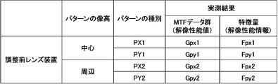
- the processor 51 calculates an MTF (Modulation Transfer Function) value, which is the resolution performance value of the lens apparatus 1 corresponding to the pattern PX1, from the image of the pattern PX1 included in each captured image that constitutes the captured image group. derive
- the MTF value expresses, as a spatial frequency characteristic, how faithfully the contrast of the pattern to be evaluated can be reproduced.
- a set of MTF values corresponding to the pattern PX1 derived here is described as an MTF data group Gpx1.
- the processor 51 derives the MTF value corresponding to the pattern PY1 from the image of the pattern PY1 included in each captured image forming the captured image group.
- a set of MTF values corresponding to the pattern PY1 derived here is described as an MTF data group Gpy1.
- the processor 51 derives the MTF value corresponding to the pattern PX2 from the image of the pattern PX2 included in each captured image forming the captured image group.
- a set of MTF values corresponding to the pattern PX2 derived here is described as an MTF data group Gpx2.
- the processor 51 derives the MTF value corresponding to the pattern PY2 from the image of the pattern PY2 included in each captured image forming the captured image group.
- a set of MTF values corresponding to the pattern PY2 derived here is described as an MTF data group Gpy2.
- the processor 51 derives the respective feature amounts of the MTF data group Gpx1, the MTF data group Gpy1, the MTF data group Gpx2, and the MTF data group Gpy2.
- Each of the MTF data group Gpx1, MTF data group Gpy1, MTF data group Gpx2, and MTF data group Gpy2 is a set of resolution performance values of the lens apparatus 1 before adjustment.
- the feature amount is resolution performance information indicating the resolution performance of the lens device 1 derived based on this set.
- FIG. 4 shows a summary of information acquired based on the group of captured images.
- each of the pattern PX1, the pattern PY1, the pattern PX2, and the pattern PY2 has the same spatial frequency
- each of the pattern PX1, the pattern PY1, the pattern PX2, and the pattern PY2 is a high-frequency pattern with a high spatial frequency. may be divided into two low-frequency patterns with low .
- a set of MTF data group Gpx1, MTF data group Gpy1, MTF data group Gpx2, and MTF data group Gpy2 is generated for two patterns, a high frequency pattern and a low frequency pattern, based on the captured image group. become.
- eight patterns of feature amounts are generated based on the group of captured images.
- a method of deriving the feature values of the MTF data group Gpx1, the MTF data group Gpy1, the MTF data group Gpx2, and the MTF data group Gpy2 will be described below using the MTF data group Gpx1 as an example.
- the method of deriving the feature amount of each of the MTF data group Gpy1, the MTF data group Gpx2, and the MTF data group Gpy2 is the same as the method of deriving the feature amount of the MTF data group Gpx1, so description thereof will be omitted.
- Two patterns of the first feature amount and the second feature amount can be cited as the feature amount to be derived.
- FIG. 5 is a diagram showing an example of the MTF data group Gpx1.
- the horizontal axis of FIG. 5 indicates the position of the fourth lens 14 (focus lens position), in other words, the relative position between the imaging position of the lens device 1 and the image sensor 3 before adjustment.
- the vertical axis in FIG. 5 indicates the MTF value corresponding to the pattern PX1 obtained by imaging at each focus lens position.
- White circles in FIG. 5 indicate MTF values according to the focus lens position.
- the processor 51 obtains the maximum and minimum values of the MTF data group Gpx1 from the differential values of the MTF data group Gpx1.
- FIG. 5 shows the minimum value B1, the minimum value B2, the minimum value B3, the minimum value B4 and the maximum value P1, the maximum value P2, and the maximum value P3 obtained by the differential value.
- the processor 51 sets the maximum value P1, the maximum value P2, and the maximum value P3 as the first feature amount of the MTF data group Gpx1.
- the MTF data group Gpx1 can be divided into a first group, a second group, and a third group according to the minimum value B1, the minimum value B2, the minimum value B3, and the minimum value B4 derived by differentiation.
- the first group is a group of MTF values corresponding to each focus lens position from the focus lens position corresponding to the minimum value B1 to the focus lens position corresponding to the minimum value B2.
- the second group is a group of MTF values corresponding to each focus lens position from the focus lens position corresponding to the minimum value B2 to the focus lens position corresponding to the minimum value B3.
- the third group is a group of MTF values corresponding to each focus lens position from the focus lens position corresponding to the minimum value B3 to the focus lens position corresponding to the minimum value B4. Therefore, the maximum value P1 becomes the first feature amount of the first group, the maximum value P2 becomes the first feature amount of the second group, and the maximum value P3 becomes the first feature amount of the third group.
- the processor 51 calculates the average values of the MTF values included in each of the first to third groups, and uses them as the first feature amount.
- the processor 51 may regard each group as a histogram, calculate an integral value, and derive an MTF value that divides this integral value in half as an average value of each group.
- the processor 51 calculates the variance of the MTF values included in each of the first to third groups, and uses these as the first feature quantity.
- the processor 51 calculates the standard deviation of each group from the variance of each group of the first to third groups, and uses them as the first feature amount.
- the processor 51 calculates the skewness and kurtosis of each group from the average value and the standard deviation of each group of the first to third groups and the moment generating function, and uses them as the first feature amount. .
- the moment generating function is a statistic expressed as a function of the mean and standard deviation. Therefore, if the average value and standard deviation of each group of the first group to the third group are obtained, the third moment indicating the skewness of each group of the first group to the third group using the moment generating function, It is possible to calculate the fourth-order moment that indicates the kurtosis of each group of the first to third groups. Examples of moment generating function, 3rd moment, and 4th moment expressions are shown below. E(X) indicates the expected value of the variable X (MTF value). ⁇ indicates the average value of X. ⁇ indicates the standard deviation of X. The square of the standard deviation may be used instead of ⁇ . r is the order.
- the processor 51 approximates the MTF data group Gpx1 with at least one Gaussian function (three in the example of FIG. 1) determined according to the design data of the lens apparatus 1 . Specifically, the processor 51 optimizes the parameters of each Gaussian function by an optimization technique such as the Levenberg-Marquardt method so that the residual between each Gaussian function prepared in advance and the MTF data group Gpx1 is minimized. decide.
- FIG. 5 shows the curves of the Gaussian function G1, the Gaussian function G2 and the Gaussian function G3 to which the determined parameters are applied.
- the processor 51 calculates the maximum value of the Gaussian function G1 and the focus lens position when the maximum value is obtained, the maximum value of the Gaussian function G2 and the focus lens position when the maximum value is obtained, the maximum value of the Gaussian function G3 and the focus lens position when the maximum value is obtained.
- the focus lens position when the maximum value is obtained is derived as the second feature amount.
- the MTF data group Gpx1 is approximated by a fourth group represented by the Gaussian function G1, a fifth group represented by the Gaussian function G2, and a sixth group represented by the Gaussian function G3. .
- the parameters of the Gaussian function G1 include the average value and standard deviation of the MTF values included in the fourth group. Therefore, the processor 51 uses the average value and standard deviation included in the parameters of the Gaussian function G1 as the second feature amount. Similarly, the processor 51 uses the average value and standard deviation included in the parameters of the Gaussian function G2 as second feature amounts, and the average value and standard deviation included in the parameters of the Gaussian function G3 as second feature amounts. By squaring each of these standard deviations, the variance of each of the fourth to sixth groups may be derived and used as the second feature amount.
- the processor 51 calculates the skewness and kurtosis of each group from the average value and standard deviation of each group of the fourth group to the sixth group and the moment generating function, and uses them as the second feature amount and
- the information consists of the focus lens position, mean value, variance, standard deviation, skewness, and kurtosis corresponding to .
- the feature amount F py1 of the MTF data group Gpy1 shown in FIG. 4 corresponds to the local maximum value (or maximum value) of each of the plurality of groups constituting the MTF data group Gpy1, and its local maximum value (or maximum value).
- This information consists of focus lens position, mean value, variance, standard deviation, skewness, and kurtosis.
- the feature amount F px2 of the MTF data group Gpx2 shown in FIG. 4 corresponds to the local maximum value (or maximum value) of each of the plurality of groups constituting the MTF data group Gpx2 and its local maximum value (or maximum value).
- This information consists of focus lens position, mean value, variance, standard deviation, skewness, and kurtosis.
- the feature amount F py2 of the MTF data group Gpy2 shown in FIG. 4 corresponds to the local maximum value (or maximum value) of each of the plurality of groups constituting the MTF data group Gpy2 and its local maximum value (or maximum value).
- This information consists of focus lens position, mean value, variance, standard deviation, skewness, and kurtosis.
- the machine learning model 52 is a model generated by machine-learning teacher data obtained by simulation .
- the wavefront aberration of the lens apparatus 1 before adjustment is output by inputting the resolution performance information consisting of the quantity Fpy2 .
- the wavefront aberration output from the machine learning model 52 is the coefficient of the Zernike polynomial, but it is not limited to this as long as it is information representing the aberration component of the wavefront aberration.
- the processor 51 inputs the feature quantity F px1 , the feature quantity F py1 , the feature quantity F px2 , and the feature quantity F py2 for the four patterns to the machine learning model 52, and the wavefront output from the machine learning model 52 accordingly.
- information on the adjustment amount of the position of the second lens 12 is generated so that the acquired wavefront aberration satisfies desired conditions, and is transmitted to the adjusting device 6 .
- the ROM of the processor 51 data in which the wavefront aberration of the lens apparatus 1 before adjustment and information on the amount of adjustment of the position of the second lens 12 are associated with each other are obtained by simulation and stored in advance. Therefore, the processor 51 reads information on the adjustment amount of the position of the second lens 12 corresponding to the obtained wavefront aberration from the ROM and transmits the information to the adjusting device 6 .
- the adjustment device 6 sets and adjusts the position of the second lens 12 according to the information received from the processor 51 .
- an operator adjusts the position of the second lens 12 by manual operation or robot operation according to information on the amount of adjustment of the position of the second lens 12 output from the processor 51. may In the above, it is not always necessary to extract feature amounts from all groups.
- the machine learning model 52 is based on the resolution performance information of a plurality of virtual lens devices (feature amounts F px1 for 4 patterns shown in FIG. 4, Based on the simulation results of the feature quantity F py1 , the feature quantity F px2 , and the feature quantity F py2 ) and the simulation results of the wavefront aberration of the plurality of virtual lens devices, the correspondence relationship between the resolution performance information and the wavefront aberration is learned. It is what is done.
- Machine learning model 52 is comprised of at least one of neural networks, convolutional neural networks, Gaussian process regression, support vector machines, multiple regression, and the like.
- FIG. 6 is a diagram showing an example of teacher data used for machine learning.
- FIG. 6 shows design data with errors of n (n is a natural number of 2 or more) virtual lens devices A1, A2, A3, A4, A5, .
- n is a natural number of 2 or more
- the virtual lens devices A1, A2, A3, A4, A5, . . . , An each constitute a virtual optical system.
- the design data with error includes the design values (shape, refractive index, etc.) of each of the first lens 11, the second lens 12, the third lens 13, and the fourth lens 14 of the lens device 1, the first lens 11, the It is data obtained by adding random errors to the design values (arrangement intervals in the optical axis direction Z, etc.) regarding the arrangement of the second lens 12, the third lens 13, and the fourth lens 14.
- FIG. 1 The design data with error includes the design values (shape, refractive index, etc.) of each of the first lens 11, the second lens 12, the third lens 13, and the fourth lens 14 of the lens device 1, the first lens 11, the It is data obtained by adding random errors to the design values (arrangement intervals in the optical axis direction Z, etc.) regarding the arrangement of the second lens 12, the third lens 13, and the fourth lens 14.
- Errors given to each of the virtual lens devices A1 to An are assembly errors of the first lens 11, second lens 12, third lens 13, and fourth lens 14, first lens 11, second lens 12, and Errors in the range of several times various errors such as manufacturing errors of each of the third lens 13 and the fourth lens 14 are randomly given by, for example, Monte Carlo simulation.
- a simulation result is associated with each of n pieces of design data with error.
- the feature quantity in the simulation results constitutes the first simulation result, and the 4 It is a simulation result of the feature amount (first feature amount or second feature amount) of the MTF data group for the pattern.
- the wavefront aberration constitutes the second simulation result, and the simulation result of the wavefront aberration (coefficient of Zernike polynomial) of the corresponding virtual lens apparatus Ak (k is any of 1 to n) is be. In this way, the machine learning model 52 is generated by obtaining each simulation result shown in FIG.
- the processor 51 determines the image quality of the lens device 1 based on a plurality of pieces of resolution performance information obtained by changing the distance between the imaging position of the lens device 1 and the position of the image sensor 3 and the machine learning model 52. Derive the wavefront aberration. Derivation of the wavefront aberration requires at least hardware for obtaining a captured image group. Therefore, the wavefront aberration can be derived easily and at low cost.
- the machine learning model 52 receives as input the resolution performance information consisting of the feature amount F px1 , the feature amount F py1 , the feature amount F px2 , and the feature amount F py2 for the four patterns shown in FIG. It outputs the wavefront aberration of the lens device 1 .
- the machine learning model 52 is a model that outputs wavefront aberration with input of a plurality of pieces of resolution performance information obtained from images of different image heights and different types of patterns. Prediction accuracy can be improved.
- a maximum value (or maximum value) indicating the characteristics of the MTF data group, and a focus lens position corresponding to the maximum value (or maximum value) mean, variance, standard deviation, skewness, and kurtosis.
- the feature amount (feature amount used as teacher data) to be input to the machine learning model 52 is the maximum value (or maximum value) indicating the characteristics of the MTF data group, the focus lens position corresponding to the maximum value (or maximum value), Prediction of wavefront aberration by the machine learning model 52 is possible if at least one of the mean, variance, standard deviation, skewness, and kurtosis is included.
- the prediction accuracy of the wavefront aberration by the machine learning model 52 is improved. found to be enhanced.
- the feature amount further includes the focus lens position, skewness, and kurtosis corresponding to the local maximum (or maximum value)
- the prediction accuracy of the wavefront aberration by the machine learning model 52 can be further improved. I found out. That is, even if the average value, the variance, and the standard deviation are omitted in the first feature amount or the second feature amount described above, the influence on the prediction accuracy of the wavefront aberration by the machine learning model 52 is small.
- the lens device 1 has only lenses as optical elements, the optical elements that the lens device 1 has may include things other than lenses, such as diaphragms, prisms, and mirrors. Also, the number of optical elements to be adjusted in the lens device 1 may be plural instead of one.
- the lens device 1 has been described as being applied to an imaging device, the lens device 1 may be applied to a projector.
- the resolution chart 2 is placed at the position of the imaging device 3, the resolution chart 2 is projected onto the screen via the lens device 1, and the image projected on the screen is displayed. , and an image pickup device 3 to obtain a group of picked-up images.
- the lens device 1 may be an optical system used in optical devices other than cameras and projectors.
- the alignment system shown in FIG. 2 is suitable when it is necessary to measure the amount of misalignment of optical elements of an optical system during assembly.
- the processor 51 acquires the resolution performance value (MTF value) using the captured image
- the resolution performance value may be acquired using another sensor instead of the captured image.
- the resolution performance value is the MTF value, but instead of the MTF value, it is also possible to use point image intensity or line image intensity.
- a wavefront aberration derivation method for deriving wavefront aberration of a lens optical system a first step of acquiring resolution performance information of the lens optical system; and a second step of inputting the resolution performance information into a machine learning model and obtaining wavefront aberration of the lens optical system from the machine learning model.
- the wavefront aberration derivation method according to (1) or (2) The wavefront aberration derivation method, wherein the resolution performance information is information based on resolution performance values including resolution, point image intensity, or line image intensity.
- the wavefront aberration derivation method is Based on a captured image obtained by imaging a subject with the imaging device in a state in which the relative position between the imaging device that images the subject through the lens optical system and the imaging position of the lens optical system is changed to a plurality of values
- the wavefront aberration derivation method according to (4), The first step is a wavefront aberration derivation method of deriving a feature amount of a data group including the resolution performance value corresponding to the relative position, and acquiring the feature amount as the resolution performance information.
- the wavefront aberration derivation method according to (5), The first step is a wavefront aberration derivation method for deriving the feature amount of a plurality of groups included in the data group.
- the wavefront aberration derivation method acquires the resolution performance value corresponding to a different image height of the captured image based on the captured image obtained by capturing the subject with an imaging device that captures the subject through the lens optical system, A wavefront aberration derivation method for deriving the feature amount corresponding to different image heights of the captured image.
- the wavefront aberration derivation method according to any one of (5) to (7), The wavefront aberration derivation method, wherein the feature amount includes at least one of a maximum value, the relative position corresponding to the maximum value, an average value, a variance, a standard deviation, a skewness, and a kurtosis.
- the data group is approximated by at least one Gaussian function, and the maximum value of the approximated Gaussian function, the relative position corresponding to the maximum value, the mean value, the standard deviation, and the variance are used as the feature amount. , skewness, and kurtosis.
- the wavefront aberration derivation method is Based on a simulation result of resolution performance information of a plurality of virtual optical systems obtained by imparting a plurality of patterns of assumed errors to the optical elements of the lens optical system, and a simulation result of wavefront aberration of the plurality of virtual optical systems, A wavefront aberration derivation method in which a correspondence relationship between resolution performance information and wavefront aberration is learned.
- the method for generating a machine learning model The method of generating a machine learning model, wherein the resolution performance information is information based on resolution performance values including resolution, point image intensity, or line image intensity.
- the resolution performance information is a solution corresponding to the relative position in a state where the relative position between the imaging position set in the optical axis direction of the virtual optical system and the imaging position of the virtual optical system has a plurality of values.
- a method for generating a machine learning model that is information based on image performance values.
- the first simulation result is a simulation result of the feature amount of the data group including the resolution performance value corresponding to different image heights at the imaging position set in the optical axis direction of the virtual optical system.
- the machine learning model generation method includes at least one of a local maximum value, the relative position corresponding to the local maximum value, an average value, a variance, a standard deviation, a skewness, and a kurtosis.
- the machine learning model generation method according to any one of (18) to (20),
- the feature amount is the maximum value of the Gaussian function when the data group is approximated by at least one Gaussian function, the relative position corresponding to the maximum value, the mean value, the standard deviation, the variance, the skewness, and the kurtosis.
- a method of generating a machine learning model comprising at least one of
- the machine learning model generation method according to any one of The method of generating a machine learning model in which the skewness and the kurtosis are derived using the average value, the standard deviation, and the moment generating function.
- a wavefront aberration derivation device for deriving wavefront aberration of a lens optical system comprising a processor that acquires resolution performance information of the lens optical system, inputs the resolution performance information into a machine learning model, and obtains wavefront aberration of the lens optical system from the machine learning model.
Landscapes
- Physics & Mathematics (AREA)
- General Physics & Mathematics (AREA)
- Engineering & Computer Science (AREA)
- Software Systems (AREA)
- Theoretical Computer Science (AREA)
- Evolutionary Computation (AREA)
- Medical Informatics (AREA)
- Data Mining & Analysis (AREA)
- Computing Systems (AREA)
- General Engineering & Computer Science (AREA)
- Computer Vision & Pattern Recognition (AREA)
- Mathematical Physics (AREA)
- Artificial Intelligence (AREA)
- Chemical & Material Sciences (AREA)
- Analytical Chemistry (AREA)
- Optics & Photonics (AREA)
- Lenses (AREA)
- Testing Of Optical Devices Or Fibers (AREA)
Priority Applications (2)
| Application Number | Priority Date | Filing Date | Title |
|---|---|---|---|
| JP2023510246A JP7576158B2 (ja) | 2021-03-31 | 2021-12-20 | 波面収差導出方法 |
| CN202180095463.9A CN116964425A (zh) | 2021-03-31 | 2021-12-20 | 波前像差导出方法、机器学习模型的生成方法、透镜光学系统的制造方法、波前像差导出装置及波前像差导出程序 |
Applications Claiming Priority (2)
| Application Number | Priority Date | Filing Date | Title |
|---|---|---|---|
| JP2021061084 | 2021-03-31 | ||
| JP2021-061084 | 2021-03-31 |
Publications (1)
| Publication Number | Publication Date |
|---|---|
| WO2022209056A1 true WO2022209056A1 (ja) | 2022-10-06 |
Family
ID=83455792
Family Applications (1)
| Application Number | Title | Priority Date | Filing Date |
|---|---|---|---|
| PCT/JP2021/047044 Ceased WO2022209056A1 (ja) | 2021-03-31 | 2021-12-20 | 波面収差導出方法、機械学習モデルの生成方法、レンズ光学系の製造方法、波面収差導出装置、及び波面収差導出プログラム |
Country Status (3)
| Country | Link |
|---|---|
| JP (1) | JP7576158B2 (https=) |
| CN (1) | CN116964425A (https=) |
| WO (1) | WO2022209056A1 (https=) |
Cited By (2)
| Publication number | Priority date | Publication date | Assignee | Title |
|---|---|---|---|---|
| CN118075590A (zh) * | 2024-03-22 | 2024-05-24 | 四川大学 | 一种基于多虚拟透镜的消色差扩景深成像系统及成像方法 |
| US20250271327A1 (en) * | 2022-04-01 | 2025-08-28 | Fogale Nanotech | Method and system for characterizing an optical lens for correcting optical aberrations introduced by said optical lens in an image |
Citations (9)
| Publication number | Priority date | Publication date | Assignee | Title |
|---|---|---|---|---|
| JP2000107129A (ja) * | 1998-10-09 | 2000-04-18 | Hoya Corp | 眼光学系のシミュレーション方法及び装置 |
| JP2003075295A (ja) * | 2001-09-03 | 2003-03-12 | Seiko Epson Corp | レンズの評価方法およびレンズ評価装置 |
| JP2012185089A (ja) * | 2011-03-07 | 2012-09-27 | Nikon Corp | 計測方法、及び計測装置 |
| JP2012220200A (ja) * | 2011-04-04 | 2012-11-12 | Canon Inc | 光学特性測定装置 |
| JP2019191121A (ja) * | 2018-04-27 | 2019-10-31 | キヤノン株式会社 | 計測方法、調整方法及び光学系の製造方法 |
| JP2020060469A (ja) * | 2018-10-11 | 2020-04-16 | キヤノン株式会社 | 収差推定方法、収差推定装置、プログラムおよび記憶媒体 |
| WO2020158325A1 (ja) * | 2019-01-31 | 2020-08-06 | 富士フイルム株式会社 | 光学部材の位置調整支援装置、光学部材の位置調整支援方法、光学部材の位置調整支援プログラム、レンズ装置の製造方法 |
| JP2021060353A (ja) * | 2019-10-09 | 2021-04-15 | キヤノン株式会社 | 光学系の内部誤差の推定方法および計測装置 |
| JP2021196230A (ja) * | 2020-06-11 | 2021-12-27 | キヤノン株式会社 | 光学特性取得方法 |
Family Cites Families (4)
| Publication number | Priority date | Publication date | Assignee | Title |
|---|---|---|---|---|
| JP2004132858A (ja) * | 2002-10-11 | 2004-04-30 | Canon Inc | 光学系の光学性能を測定する装置及び方法 |
| JP2007033168A (ja) * | 2005-07-26 | 2007-02-08 | Tochigi Nikon Corp | レンズ検査方法およびレンズ検査装置 |
| CN105283118B (zh) * | 2013-06-10 | 2018-01-02 | 埃西勒国际通用光学公司 | 用于确定待测试光学系统的波前像差数据的方法 |
| WO2020002143A1 (en) * | 2018-06-25 | 2020-01-02 | Asml Netherlands B.V. | Wavefront optimization for tuning scanner based on performance matching |
-
2021
- 2021-12-20 JP JP2023510246A patent/JP7576158B2/ja active Active
- 2021-12-20 WO PCT/JP2021/047044 patent/WO2022209056A1/ja not_active Ceased
- 2021-12-20 CN CN202180095463.9A patent/CN116964425A/zh active Pending
Patent Citations (9)
| Publication number | Priority date | Publication date | Assignee | Title |
|---|---|---|---|---|
| JP2000107129A (ja) * | 1998-10-09 | 2000-04-18 | Hoya Corp | 眼光学系のシミュレーション方法及び装置 |
| JP2003075295A (ja) * | 2001-09-03 | 2003-03-12 | Seiko Epson Corp | レンズの評価方法およびレンズ評価装置 |
| JP2012185089A (ja) * | 2011-03-07 | 2012-09-27 | Nikon Corp | 計測方法、及び計測装置 |
| JP2012220200A (ja) * | 2011-04-04 | 2012-11-12 | Canon Inc | 光学特性測定装置 |
| JP2019191121A (ja) * | 2018-04-27 | 2019-10-31 | キヤノン株式会社 | 計測方法、調整方法及び光学系の製造方法 |
| JP2020060469A (ja) * | 2018-10-11 | 2020-04-16 | キヤノン株式会社 | 収差推定方法、収差推定装置、プログラムおよび記憶媒体 |
| WO2020158325A1 (ja) * | 2019-01-31 | 2020-08-06 | 富士フイルム株式会社 | 光学部材の位置調整支援装置、光学部材の位置調整支援方法、光学部材の位置調整支援プログラム、レンズ装置の製造方法 |
| JP2021060353A (ja) * | 2019-10-09 | 2021-04-15 | キヤノン株式会社 | 光学系の内部誤差の推定方法および計測装置 |
| JP2021196230A (ja) * | 2020-06-11 | 2021-12-27 | キヤノン株式会社 | 光学特性取得方法 |
Cited By (2)
| Publication number | Priority date | Publication date | Assignee | Title |
|---|---|---|---|---|
| US20250271327A1 (en) * | 2022-04-01 | 2025-08-28 | Fogale Nanotech | Method and system for characterizing an optical lens for correcting optical aberrations introduced by said optical lens in an image |
| CN118075590A (zh) * | 2024-03-22 | 2024-05-24 | 四川大学 | 一种基于多虚拟透镜的消色差扩景深成像系统及成像方法 |
Also Published As
| Publication number | Publication date |
|---|---|
| CN116964425A (zh) | 2023-10-27 |
| JPWO2022209056A1 (https=) | 2022-10-06 |
| JP7576158B2 (ja) | 2024-10-30 |
Similar Documents
| Publication | Publication Date | Title |
|---|---|---|
| CN104949763B (zh) | 一种基于逆哈特曼原理的透镜波前像差测量方法 | |
| US8260024B2 (en) | Systems and methods for measuring surface shape | |
| US7831105B2 (en) | Method for determining the image quality of an optical imaging system | |
| JP6494205B2 (ja) | 波面計測方法、形状計測方法、光学素子の製造方法、光学機器の製造方法、プログラム、波面計測装置 | |
| CN108012147B (zh) | Ar成像系统虚像距测试方法及装置 | |
| KR20190121689A (ko) | 수차 보정을 위한 카메라의 보정 모델을 생성하기 위한 방법 | |
| CN1747682A (zh) | 眼科的塔尔波特-莫尔波前传感器 | |
| WO2018029950A1 (ja) | 較正装置、較正方法、光学装置、撮影装置、および投影装置 | |
| TWI484283B (zh) | 影像計算量測方法、影像計算量測裝置及影像檢查裝置 | |
| CN110261069B (zh) | 一种用于光学镜头的检测方法 | |
| CA3132556A1 (en) | System and method of wavefront sensing with engineered images | |
| US9990724B2 (en) | Image recording simulation in a coordinate measuring machine | |
| CN102667439A (zh) | 用于测量波前像差的方法和波前像差测量设备 | |
| JP7576158B2 (ja) | 波面収差導出方法 | |
| CN106556357A (zh) | 一种基于一维无衍射光束测量三维面形的装置及方法 | |
| US20250271327A1 (en) | Method and system for characterizing an optical lens for correcting optical aberrations introduced by said optical lens in an image | |
| JP2025121323A (ja) | 計測装置、計測方法および光学系の製造方法 | |
| JP7059406B2 (ja) | 光学部材の位置調整支援装置、光学部材の位置調整支援方法、光学部材の位置調整支援プログラム、レンズ装置の製造方法 | |
| CN108278977B (zh) | 测量仪及测量方法 | |
| US20250264372A1 (en) | Apparatus and method for testing an astigmatic optical test object | |
| JP2025090472A (ja) | 収差推定装置、収差推定方法、プログラムおよび記憶媒体 | |
| WO2020036488A1 (en) | Optical device and method for measuring spatially-varying aberrations of an imaging system | |
| TW202607447A (zh) | 用於將光學物鏡特徵化的方法及系統 | |
| CN119135874A (zh) | 一种光学系统像差检查方法及装置 | |
| CN119147221A (zh) | 一种自聚焦透镜阵列焦点深度的测试方法及装置 |
Legal Events
| Date | Code | Title | Description |
|---|---|---|---|
| 121 | Ep: the epo has been informed by wipo that ep was designated in this application |
Ref document number: 21935205 Country of ref document: EP Kind code of ref document: A1 |
|
| DPE1 | Request for preliminary examination filed after expiration of 19th month from priority date (pct application filed from 20040101) | ||
| WWE | Wipo information: entry into national phase |
Ref document number: 2023510246 Country of ref document: JP |
|
| WWE | Wipo information: entry into national phase |
Ref document number: 202180095463.9 Country of ref document: CN |
|
| NENP | Non-entry into the national phase |
Ref country code: DE |
|
| 122 | Ep: pct application non-entry in european phase |
Ref document number: 21935205 Country of ref document: EP Kind code of ref document: A1 |