WO2022208956A1 - 医療用管状体搬送装置 - Google Patents
医療用管状体搬送装置 Download PDFInfo
- Publication number
- WO2022208956A1 WO2022208956A1 PCT/JP2021/039049 JP2021039049W WO2022208956A1 WO 2022208956 A1 WO2022208956 A1 WO 2022208956A1 JP 2021039049 W JP2021039049 W JP 2021039049W WO 2022208956 A1 WO2022208956 A1 WO 2022208956A1
- Authority
- WO
- WIPO (PCT)
- Prior art keywords
- tubular body
- medical
- distal end
- medical use
- proximal end
- Prior art date
Links
- 238000003780 insertion Methods 0.000 claims abstract description 67
- 230000037431 insertion Effects 0.000 claims abstract description 67
- 238000003860 storage Methods 0.000 claims description 124
- 230000001681 protective effect Effects 0.000 claims description 73
- 230000002265 prevention Effects 0.000 claims description 63
- 230000004308 accommodation Effects 0.000 abstract 7
- 230000003902 lesion Effects 0.000 description 21
- 238000000034 method Methods 0.000 description 11
- 230000000694 effects Effects 0.000 description 10
- 239000002184 metal Substances 0.000 description 8
- 229910052751 metal Inorganic materials 0.000 description 8
- 238000005452 bending Methods 0.000 description 6
- 210000004204 blood vessel Anatomy 0.000 description 5
- 239000000463 material Substances 0.000 description 5
- 230000007246 mechanism Effects 0.000 description 5
- 210000000013 bile duct Anatomy 0.000 description 4
- 238000002788 crimping Methods 0.000 description 4
- 239000011347 resin Substances 0.000 description 4
- 229920005989 resin Polymers 0.000 description 4
- 238000003466 welding Methods 0.000 description 4
- 239000010410 layer Substances 0.000 description 3
- 238000004519 manufacturing process Methods 0.000 description 3
- 239000010935 stainless steel Substances 0.000 description 3
- 229910001220 stainless steel Inorganic materials 0.000 description 3
- 230000001954 sterilising effect Effects 0.000 description 3
- 238000004659 sterilization and disinfection Methods 0.000 description 3
- 238000004804 winding Methods 0.000 description 3
- 239000004952 Polyamide Substances 0.000 description 2
- 230000006866 deterioration Effects 0.000 description 2
- 201000010099 disease Diseases 0.000 description 2
- 208000037265 diseases, disorders, signs and symptoms Diseases 0.000 description 2
- 210000001198 duodenum Anatomy 0.000 description 2
- 210000001035 gastrointestinal tract Anatomy 0.000 description 2
- 238000001727 in vivo Methods 0.000 description 2
- 238000005304 joining Methods 0.000 description 2
- 230000005012 migration Effects 0.000 description 2
- 238000013508 migration Methods 0.000 description 2
- 229920002647 polyamide Polymers 0.000 description 2
- 239000002861 polymer material Substances 0.000 description 2
- 230000008569 process Effects 0.000 description 2
- 206010004593 Bile duct cancer Diseases 0.000 description 1
- IAYPIBMASNFSPL-UHFFFAOYSA-N Ethylene oxide Chemical compound C1CO1 IAYPIBMASNFSPL-UHFFFAOYSA-N 0.000 description 1
- 208000031481 Pathologic Constriction Diseases 0.000 description 1
- 239000004698 Polyethylene Substances 0.000 description 1
- FAPWRFPIFSIZLT-UHFFFAOYSA-M Sodium chloride Chemical compound [Na+].[Cl-] FAPWRFPIFSIZLT-UHFFFAOYSA-M 0.000 description 1
- 208000007536 Thrombosis Diseases 0.000 description 1
- 239000000853 adhesive Substances 0.000 description 1
- 230000001070 adhesive effect Effects 0.000 description 1
- 229910045601 alloy Inorganic materials 0.000 description 1
- 239000000956 alloy Substances 0.000 description 1
- 230000008901 benefit Effects 0.000 description 1
- 210000000941 bile Anatomy 0.000 description 1
- 208000026900 bile duct neoplasm Diseases 0.000 description 1
- 210000003445 biliary tract Anatomy 0.000 description 1
- 208000006990 cholangiocarcinoma Diseases 0.000 description 1
- 238000004891 communication Methods 0.000 description 1
- 229920001971 elastomer Polymers 0.000 description 1
- 239000000806 elastomer Substances 0.000 description 1
- 239000012530 fluid Substances 0.000 description 1
- 230000012447 hatching Effects 0.000 description 1
- 210000003090 iliac artery Anatomy 0.000 description 1
- 238000002347 injection Methods 0.000 description 1
- 239000007924 injection Substances 0.000 description 1
- 239000011229 interlayer Substances 0.000 description 1
- 239000007769 metal material Substances 0.000 description 1
- 150000002739 metals Chemical class 0.000 description 1
- 229910001000 nickel titanium Inorganic materials 0.000 description 1
- 210000000277 pancreatic duct Anatomy 0.000 description 1
- 230000002093 peripheral effect Effects 0.000 description 1
- 239000012466 permeate Substances 0.000 description 1
- -1 polyethylene Polymers 0.000 description 1
- 229920000573 polyethylene Polymers 0.000 description 1
- 239000011780 sodium chloride Substances 0.000 description 1
- 230000036262 stenosis Effects 0.000 description 1
- 208000037804 stenosis Diseases 0.000 description 1
- 230000002966 stenotic effect Effects 0.000 description 1
- 239000000758 substrate Substances 0.000 description 1
- 238000001356 surgical procedure Methods 0.000 description 1
- 230000001225 therapeutic effect Effects 0.000 description 1
- XLYOFNOQVPJJNP-UHFFFAOYSA-N water Substances O XLYOFNOQVPJJNP-UHFFFAOYSA-N 0.000 description 1
- 238000009941 weaving Methods 0.000 description 1
Images


Classifications
-
- A—HUMAN NECESSITIES
- A61—MEDICAL OR VETERINARY SCIENCE; HYGIENE
- A61B—DIAGNOSIS; SURGERY; IDENTIFICATION
- A61B17/00—Surgical instruments, devices or methods, e.g. tourniquets
-
- A—HUMAN NECESSITIES
- A61—MEDICAL OR VETERINARY SCIENCE; HYGIENE
- A61F—FILTERS IMPLANTABLE INTO BLOOD VESSELS; PROSTHESES; DEVICES PROVIDING PATENCY TO, OR PREVENTING COLLAPSING OF, TUBULAR STRUCTURES OF THE BODY, e.g. STENTS; ORTHOPAEDIC, NURSING OR CONTRACEPTIVE DEVICES; FOMENTATION; TREATMENT OR PROTECTION OF EYES OR EARS; BANDAGES, DRESSINGS OR ABSORBENT PADS; FIRST-AID KITS
- A61F2/00—Filters implantable into blood vessels; Prostheses, i.e. artificial substitutes or replacements for parts of the body; Appliances for connecting them with the body; Devices providing patency to, or preventing collapsing of, tubular structures of the body, e.g. stents
- A61F2/02—Prostheses implantable into the body
- A61F2/04—Hollow or tubular parts of organs, e.g. bladders, tracheae, bronchi or bile ducts
- A61F2/06—Blood vessels
- A61F2/07—Stent-grafts
-
- A—HUMAN NECESSITIES
- A61—MEDICAL OR VETERINARY SCIENCE; HYGIENE
- A61F—FILTERS IMPLANTABLE INTO BLOOD VESSELS; PROSTHESES; DEVICES PROVIDING PATENCY TO, OR PREVENTING COLLAPSING OF, TUBULAR STRUCTURES OF THE BODY, e.g. STENTS; ORTHOPAEDIC, NURSING OR CONTRACEPTIVE DEVICES; FOMENTATION; TREATMENT OR PROTECTION OF EYES OR EARS; BANDAGES, DRESSINGS OR ABSORBENT PADS; FIRST-AID KITS
- A61F2/00—Filters implantable into blood vessels; Prostheses, i.e. artificial substitutes or replacements for parts of the body; Appliances for connecting them with the body; Devices providing patency to, or preventing collapsing of, tubular structures of the body, e.g. stents
- A61F2/95—Instruments specially adapted for placement or removal of stents or stent-grafts
- A61F2/962—Instruments specially adapted for placement or removal of stents or stent-grafts having an outer sleeve
- A61F2/966—Instruments specially adapted for placement or removal of stents or stent-grafts having an outer sleeve with relative longitudinal movement between outer sleeve and prosthesis, e.g. using a push rod
Definitions
- the present invention relates to a medical tubular body delivery device, which is a device for delivering a medical tubular body such as a stent into the body.
- Medical tubular bodies typified by stents are medical devices used to treat various diseases caused by stenosis or blockage of lumens in the body, such as gastrointestinal tracts such as bile ducts and pancreatic ducts, and blood vessels such as iliac arteries. be.
- Medical tubular bodies are used to expand a lesion such as a stenotic or obstructed site from the inside and remain in the lesion to maintain the inner diameter of the lumen, or to treat a thrombus generated in or around the lesion.
- a lesion such as a stenotic or obstructed site from the inside and remain in the lesion to maintain the inner diameter of the lumen, or to treat a thrombus generated in or around the lesion.
- a medical tubular body is inserted into the biliary tract to drain bile from the bile duct to the duodenum side in a biliary obstruction due to bile duct cancer.
- the placement method will be described below.
- an endoscope is inserted from the mouth to the entrance (papilla) of the bile duct of the duodenum.
- a guidewire is then delivered to the lesion through the endoscope.
- the medical tubular body conveying device is conveyed to the lesion along the guide wire. Then, the medical tubular body conveying device is operated to place the medical tubular body in the affected area.
- Patent Document 1 discloses a first tubular member having a distal end for receiving a stent, a second tubular member longitudinally slidable on the first tubular member, and a second tubular member. a third tubular member disposed over at least a portion of the two tubular members and rotatable relative to the first tubular member and the second tubular member;
- a stent delivery system is disclosed having a handle body retractable relative to a tubular member.
- the tubular body transportation device for medical use is often greatly twisted.
- it is necessary to eliminate the twist by turning an operation handle for indwelling the medical tubular body provided on the proximal side of the medical tubular body conveying device in the affected area.
- the medical tubular body may be mistakenly placed in a non-lesioned part of the lumen of the body. There is also a risk of being detained for a long time.
- a stent which is a tubular body for medical use, is placed between a first tube member and a second tube member, delivered to a lesion site, delivered to the lesion site, and then transported to a handle main body. is operated to retract the second tubular member with respect to the first tubular member, thereby exposing the stent from the second tubular member and deploying and indwelling the stent at the lesion site.
- a third tubular member is provided that is rotatable relative to the first and second tubular members to alleviate compressive forces caused by twisting the third tubular member while in a tortuous in vivo lumen. It has become a stent delivery system that can
- the third tubular member is only rotatable with respect to the first and second tubular members, and the structure connected to the handle body for the stent-carrying first and second tubular members. It has become. Therefore, when the first pipe member and the second pipe member are twisted, the twisting of the first pipe member and the second pipe member cannot be eliminated by twisting the third pipe member, and the operation of turning the handle body is still required. Met.
- the present invention has been made in view of the above-mentioned circumstances, and its primary object is to eliminate the large torsion that occurs in a medical tubular body conveying device during conveyance of the medical tubular body conveying device.
- Another object of the present invention is to provide a medical tubular body conveying device that eliminates the need for an operator to turn an operating handle, which is not related to medical treatment.
- a second object of the present invention is to provide a medical tubular body delivery device having a medical tubular body deploying mechanism by means of a moving body driven by an operating handle, wherein the medical tubular body such as a stent is moved by the operating handle.
- the storage member When the storage member is attached in a rotatable state, it prevents the storage member from advancing (moving toward the distal end of the catheter), preventing the storage member from colliding with the distal tip of the inner tube, and preventing medical tubular bodies such as stents. To prevent deterioration of the placement accuracy of a catheter.
- a medical tubular body delivery device that can solve the above-described problems is a device for delivering a medical tubular body into the body, comprising: and an operating handle for moving the storage member proximally with respect to the inner tube.
- the operation handle holds the inner tube and stores the storage member. It comprises a base, a moving body that can move in the longitudinal direction of the storage member, and a driving part that moves the moving body, and the moving body has a holding part provided with an insertion hole through which the storage member can be rotatably inserted.
- the storage member is provided with an advance prevention portion on the proximal side of the insertion hole, and the movement of the movable body and the storage member by the driving portion is enabled by abutment of the advance prevention portion and the holding portion. is.
- the advance prevention portion is arranged in contact with the holding portion.
- the tubular body conveying device for medical use of the present invention preferably includes a retraction preventing portion arranged so that the storage member can abut against the holding portion on the distal side of the insertion hole.
- the storage member includes an outer tube in which the medical tubular body is arranged in a lumen, and a pulling member connected to the outer tube, and the proximal end side of the outer tube and the pulling member connected to the outer tube. , a portion of the inner tube extending proximally from the proximal end of the outer tube, and a traction member disposed in the lumen, and a guidewire port for passing a guidewire through the lumen of the inner tube.
- a protective tube is preferably provided.
- the tubular body conveying device for medical use of the present invention includes a protective member that abuts on the distal end side of the retraction prevention portion and is arranged on the traction member.
- the protective member is preferably attached to the base.
- the protective member is preferably attached to the protective tube.
- the protective tube is preferably attached to the base so as to be rotatable with respect to the operating handle.
- the inner tube is preferably attached to the base so as to be rotatable with respect to the operating handle.
- a medical tubular body conveying device that can solve the above problems is a device that conveys a medical tubular body into the body, and includes a storage member in which the medical tubular body is arranged in a lumen on the distal end side. an inner tube disposed in the lumen of the medical tubular body; and an operating handle for moving the storage member proximally with respect to the inner tube, the operating handle holding the inner tube and the storage member.
- a moving body capable of moving in the longitudinal direction of the storage member; and a drive unit for moving the moving body, and the moving body is provided with an insertion hole through which the storage member can be rotatably inserted.
- the storage member has an advance prevention portion on the proximal side of the insertion hole, and the movement of the moving body and the storage member by the driving portion is enabled by abutment between the advance prevention portion and the holding portion. It is characterized.
- a medical tubular body conveying device that can solve the above problems is a device for conveying a medical tubular body into the body, comprising: a storage member in which the medical tubular body is arranged in a lumen; an inner tube disposed within the lumen of the tubular body; and a handle for moving the containment member proximally with respect to the inner tube, the handle extending in the longitudinal direction of the containment member and the base containing the containment member.
- a moving body that can move into the body, the moving body has an insertion passage through which the storage member is rotatably inserted; , in contact with the moving object.
- the handle preferably holds the inner tube.
- the distal end of the advance prevention section preferably contacts the proximal end of the movable body.
- the distal end of the advance prevention section can be positioned further distally than the proximal end of the movable body.
- the distal end of the advancement preventing portion is positioned further distally than the proximal end of the insertion passage, and the proximal end of the advancement preventing portion is located further distally than the distal end of the insertion passage. is also proximal.
- the moving body has a holding portion, and the insertion path is formed in the holding portion.
- the advance prevention section is disposed in contact with the holding section.
- the distal end of the advance prevention section contacts the proximal end of the holding section.
- the distal end of the advance preventing portion can be positioned further distally than the proximal end of the holding portion.
- the storage member has a retraction prevention section on the distal side of the advance prevention section, and at least part of the retraction prevention section is in contact with the moving body.
- the proximal end of the anti-retreat part is in contact with the distal end of the movable body.
- the proximal end of the retraction prevention part can be positioned closer to the proximal side than the distal end of the movable body.
- the distal end of the retraction preventing portion is located on the distal side of the proximal end of the insertion passage, and the proximal end of the retraction preventing portion is located further than the distal end of the insertion passage. is also proximal.
- the anti-retreat part is arranged in contact with the holding part.
- the proximal end of the anti-retreat part is in contact with the distal end of the holding part.
- the proximal end of the anti-retreat part can be positioned closer to the proximal side than the distal end of the holding part.
- the storage member comprises an outer tube in which the medical tubular body is arranged in the lumen, and a traction member connected to the outer tube.
- the pull member has a protective tube disposed within the lumen, the protective tube having a guidewire port in communication with the inner tube through which a guidewire is passed through the lumen.
- the tubular body conveying device for medical use of the present invention preferably has a protective member disposed on the traction member, and the protective member preferably abuts against the retraction prevention portion.
- the protective member is preferably fixed to the base.
- the protective member is preferably fixed to the protective tube.
- the protective tube is preferably fixed to the base and rotatable with respect to the handle.
- the inner tube is preferably fixed to the base and rotatable with respect to the handle.
- the storage member for the medical tubular body such as a stent is rotatable with respect to the handle, if the conventional medical tubular body conveying device When the body is transported, the large torsion that occurs in the tubular body transporting apparatus for medical use does not occur.
- the storage member can be prevented from moving forward in the axial direction, the storage member and the distal end tip can be prevented from colliding with each other and being damaged, and the positional relationship between the distal end of the storage member and the medical tubular body can be displaced. It is also possible to prevent deterioration of placement accuracy of the medical tubular body due to
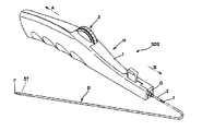
- FIG. 1 is an overall perspective view showing a medical tubular body conveying device according to an embodiment of the present invention
- FIG. Fig. 2 is an enlarged perspective view of a main part showing the configuration of the distal end portion of the delivery catheter according to the embodiment of the present invention
- FIG. 2 is a plan view of the portion where the outer tube, the inner tube, and the protective tube of the medical tubular body conveying device shown in FIG. 1 are present
- 1 is an exploded perspective view of a handle according to an embodiment of the invention
- FIG. FIG. 4 is an enlarged cross-sectional view of a portion where a moving body, a traction member, and a holding portion are present in the handle according to the embodiment of the present invention
- a medical tubular body delivery device SDS (hereinafter also referred to as a stent delivery system) according to an embodiment of the present invention includes a coaxial inner tube 1 and a medical tubular body ST such as a stent.
- a medical tubular body ST (hereinafter also referred to as a stent) held at the distal end of the delivery catheter D, and an operating handle H (hereinafter referred to as a handle (also written as
- proximal side refers to the direction toward the hand side of the user or the operator with respect to the extending direction of the stent delivery system SDS or the longitudinal direction of the delivery catheter D
- distal side refers to the proximal direction. It refers to the side opposite direction, ie, the direction of the subject's side where the stent ST is placed.
- the end on the proximal side is the proximal end
- the vicinity of the proximal end is the proximal end
- the end on the distal side is the distal end
- the vicinity of the distal end is the distal end and
- the stent ST is a self-expanding tubular body made of, for example, a nickel-titanium alloy, which is a superelastic alloy, and has a mesh configuration.
- the stent ST is held at the distal end of the delivery catheter D in a state of being reduced in diameter.
- the distal tip F in the enlarged perspective view of the essential part of FIG. It is formed in a tapered shape depending on the material.
- FIG. 1 shows a delivery catheter D, which is an example of a catheter, and a handle H attached to this delivery catheter D.
- FIG. A system including a handle H and a delivery catheter D attached to the handle H is referred to as a stent delivery system SDS.
- the handle H moves the housing member 2 to the proximal side with respect to the inner tube 1.
- a handle H preferably holds the inner tube 1 .
- the storage member 2 is arranged in the lumen on the distal end side of the medical tubular body ST.
- the stent ST is arranged in the lumen on the distal end side of the housing member 2 .
- the storage member 2 preferably includes an outer tube 15 in which the medical tubular body ST is arranged, and a traction member 13 connected to the outer tube 15 . Further, as shown in FIG. 3, the storage member 2 may be composed of an outer tube 15 that stores the stent ST, and a pulling member 13 fixed to the proximal side of the outer tube 15 . Furthermore, the storage member 2 may comprise a protective tube 14 covering part of the outer tube 15 and the traction member 13 . Protective tube 14 is preferably positioned in the lumen where the proximal end of outer tube 15 and retraction member 13 are located.
- a distal tip F is preferably provided at the distal end of the inner tube 1 .
- the distal tip F has a lumen which preferably communicates with the lumen of the inner tube 1 . Since the distal tip F constitutes the distal end of the delivery catheter D, when the delivery catheter D is inserted into the forceps channel of the endoscope to transport the stent ST to the lesion site, the distal end of the delivery catheter D can be can be prevented from damaging the in vivo lumen. In addition, since the tip F is located at the distal end of the delivery catheter D, the followability of the delivery catheter D to the preceding guide wire and forceps channel and the deliverability of the tip of the delivery catheter D to the lesion are enhanced. and the operability of the stent delivery system SDS is improved.
- FIG. 3(a) is a partial plan view of the stent delivery system SDS shown in FIG. 1, showing a plan view of a state in which the stent ST is housed in the delivery catheter D, similar to FIG. 2(a).
- FIG. 3(b) is a plan view of the stent delivery system SDS shown in FIG. 1 in which the outer tube 15 is moved proximally and the stent ST is exposed from the stent delivery system SDS and radially expanded. show.
- the outer tube 15 is located at the distal part of the storage member 2, and the stent ST is arranged in the lumen of the outer tube 15.
- the outer tube 15 is formed to be movable in the far-near direction with respect to the inner tube 1 and the protective tube 14, and FIG. (b) shows a state in which the outer tube 15 is located on the most proximal side.
- the outer tube 15 protects the stent ST from being exposed outside the storage member 2 as shown in FIG. 3(a) when the stent ST is transported to the lesion site.
- the outer tube 15 functions to hold the stent ST in a reduced diameter state during delivery of the stent ST, thereby facilitating delivery of the stent ST to the lesion site.
- the length of the outer tube 15 in the far-near direction can be appropriately set according to the length in the far-near direction of the stent ST placed in the lumen, and can be, for example, about 50 mm to 800 mm.
- the range in which the outer tube 15 can move in the far-near direction can be appropriately set according to the length of the stent ST placed in the lumen of the outer tube 15 in the far-near direction. Long is preferred.
- the outer diameter of the outer tube 15 may be, for example, approximately 0.5 mm to 3.5 mm.
- the perspective direction can be rephrased as the longitudinal axis direction or the longitudinal direction.
- a typical example of the medical tubular body ST is a stent.
- a stent By using a stent, it is possible to treat various diseases caused by narrowing or obstruction of a living body lumen such as a digestive tract such as a bile duct or a blood vessel.
- the medical tubular body ST includes a single linear metal or coil-shaped body made of a polymer material, a metal tube or a tube made of a polymer material cut out with a laser or the like, or a linear member. There are those assembled by welding, and those formed by weaving multiple linear metals.
- a stent graft, an obturator, an injection catheter, a prosthetic valve, etc. can be used in addition to a stent.
- the medical tubular body ST is (i) mounted (mounted) on the surface of a balloon, transported to the lesion site, and expanded by the balloon at the lesion site. and (ii) the self-expanding type, in which the medical tubular body is transported to the lesion while the expansion is suppressed, and the medical tubular body expands by itself by removing the member that suppresses the expansion at the lesion. can be classified.
- the stent delivery system SDS is preferably used for carrying a self-expanding medical tubular body, and the outer tube 15 functions as a member that suppresses expansion of the stent ST.
- the stent ST contracts in the radial direction and expands in the longitudinal direction, so that the stent ST assumes a diameter-reduced state that is a more elongated cylindrical shape than in the expanded state.
- the diameter of the self-expanding medical tubular body can be made smaller than the balloon-expandable medical tubular body.
- the inner tube 1 is arranged in the lumen of the medical tubular body ST. That is, the inner tube 1 is arranged in the lumen of the storage member 2 and the lumen of the stent ST.
- the inner tube 1 is arranged in the lumen of the outer tube 15 and the lumen of the stent ST, and extends proximally from the proximal end of the outer tube 15 .
- the stent ST is delivered into the body by the stent delivery system SDS, the stent ST is arranged between the inner tube 1 and the outer tube 15 in the radial direction.
- a guide wire is passed through the lumen of the inner tube 1 .
- the length of the inner tube 1 in the far-near direction may be, for example, about 800 mm to 3000 mm.
- the outer diameter of the inner tube 1 may be, for example, approximately 0.3 mm to 3.0 mm.
- the proximal end of the distal tip F is preferably positioned closer to the proximal side than the distal end of the outer tube 15 when the outer tube 15 is positioned on the most distal side. That is, the proximal end of distal tip F is preferably in the lumen of the distal end of outer tube 15 . Since the proximal end of the distal tip F is in the lumen of the distal end of the outer tube 15, when the delivery catheter D is inserted into the forceps channel of the endoscope to convey the stent ST to the lesion site, The outer tube 15 can easily follow the bending motion of the distal tip F, and the operability of the delivery catheter D can be improved when the stent ST is transported to the lesion site.
- a protective tube 14 in which the proximal end of the outer tube 15 is arranged in the lumen.
- the proximal end of the outer tube 15 and the inner tube 1 are arranged in the lumen of the protective tube 14 , and the protective tube 14 extends proximally from the proximal end of the outer tube 15 .
- a handle H is provided on the proximal side of the protective tube 14 for the user to operate the stent delivery system SDS.
- the length of the protection tube 14 in the distance direction may be, for example, about 500 mm to 2200 mm.
- the outer diameter of the protective tube 14 may be, for example, approximately 0.5 mm to 3.5 mm.
- the proximal end of the outer tube 15 is preferably placed in the lumen of the protective tube 14 with the outer tube 15 positioned most proximally and most distally.
- the length of the proximal end portion of the outer tube 15 disposed in the lumen of the protective tube 14 in the far-near direction may be, for example, 1 mm or more and 50 mm or less when the outer tube 15 is located at the most distal side.
- At least part of the portion of the inner tube 1 extending proximally from the proximal end of the outer tube 15 is disposed in the lumen of the protective tube 14, and the portion further distal than that, specifically The portion overlapping the proximal end of the outer tube 15 that is placed in the lumen of the protective tube 14 is also placed in the lumen of the protective tube 14 .
- the protective tube 14 is preferably provided with a guidewire port 12 for passing a guidewire through the lumen of the inner tube 1 . That is, the protective tube 14 preferably has a guidewire port 12 through which a guidewire is inserted through the lumen and communicates with the inner tube 1 .
- the guidewire port 12 is provided as an opening for passing a guidewire inside the delivery catheter D. As shown in FIG.
- the guidewire normally enters the distal end (tip F) of the inner tube 1 and exits the guidewire port 12 to the lumen of the inner tube 1. is inserted into the In this case, the guidewire port 12 serves as an opening for leading the guidewire from the lumen of the inner tube 1 to the outside of the stent delivery system SDS.
- the position of the guidewire port 12 in the far-near direction may be appropriately set according to the type of stent delivery system SDS, ie, rapid exchange type or over-the-wire type.
- FIG. 3 shows a configuration example of a rapid exchange type medical tubular body delivery device in which a guide wire is inserted halfway from the distal end to the proximal end of the shaft portion. It can also be applied to an over-the-wire type medical tubular body delivery device in which a guide wire is inserted from the distal end to the proximal end of the shaft portion.
- Guidewire port 12 is preferably proximal to the proximal end of outer tube 15, with outer tube 15 being most proximal.
- a traction member 13 is preferably connected to the proximal end of the outer tube 15 .
- a retraction member 13 extends proximally from the proximal end of outer tube 15, is disposed within the lumen of protective tube 14, and is connected to handle H, either directly or via another member.
- the handle H By manipulating the handle H, the traction member 13 and the outer tube 15 can be moved in the far-near direction. For example, by pulling the pulling member 13 proximally from the state shown in FIG. ), the stent ST can be exposed outside the delivery catheter D and left in the body.
- the traction member 13 is sent distally, the outer tube 15 is moved distally with respect to the inner tube 1 and the protective tube 14, and the stent ST is pulled outward again. It is also possible to house the stent ST in the lumen of the tube 15 and adjust the indwelling position of the stent ST. It should be noted that the inner tube 1 and the protective tube 14 do not move proximally by pulling the pulling member 13 proximally.
- traction member 13 may be connected to the inner surface of outer tube 15 or may be connected to the outer surface of outer tube 15 . may be connected to the peripheral wall between the Alternatively, the proximal end portion of the outer tube 15 may be of a multi-layer structure, the distal end portion of the pull member 13 may be arranged between the layers, and the pull member 13 may be connected to the outer tube 15 .
- known joining means such as adhesion with an adhesive, welding, fitting, and interlayer pressure bonding of the outer tube 15 having a multi-layer structure can be employed.
- Only one traction member 13 may be provided, or a plurality thereof may be provided. When a plurality of traction members 13 are provided, it is preferable that the plurality of traction members 13 be provided at different positions in the circumferential direction of the outer tube 15 . In order to make the outer diameter of the protective tube 14 smaller, it is preferable that only one pulling member 13 is provided.
- the delivery catheter D is configured as described above, so that the outer tube 15 is pulled proximally with respect to the inner tube 1 and the protective tube 14, and the stent ST is placed in the body lumen. It becomes easy to indwell at a desired position with high accuracy. Specifically, when the outer tube 15 is moved proximally, the outer tube 15 can be housed in the lumen of the protective tube 14, so when the outer tube 15 is moved in the far-near direction, the outer tube 15 can be It is possible to reduce frictional resistance caused by the tube 15 coming into contact with the forceps channel and the forceps port of the endoscope.
- the operating load when moving the outer tube 15 in the far-near direction is reduced, and the stent ST can be stably deployed.
- the entire delivery catheter D can be moved to the proximal side. can be suppressed, and the stent ST can be placed at a desired position with high accuracy.
- the space between the outer tube 15 and the inner tube 1 and the space between the protective tube 14 and the inner tube 1 are separated. It is desirable to evacuate the air present in the intervening space and replace it with water or saline.
- the outer tube 15 and the inner tube 1 can be separated when moving the outer tube 15 in the near and far directions.
- the frictional resistance between the outer tube 15 and the protective tube 14 By reducing the frictional resistance between the outer tube 15 and the protective tube 14 , the operating load of the outer tube 15 can be further reduced.
- the air inside the delivery catheter D is removed so that the air is mixed in the blood vessel when the outer tube 15 is moved in the far-near direction. You can also prevent it from doing so.
- a fluid such as ethylene oxide gas
- the sterilization medium can easily permeate into the delivery catheter D and be discharged. As a result, sterilization efficiency is improved, and safety and production efficiency can also be improved.
- Fig. 4 shows a perspective view of the handle H according to the embodiment of the present invention, which is disassembled in the longitudinal direction.
- the handle H includes a base I that houses the storage member 2 and a movable body 5 that can move in the longitudinal direction of the storage member 2 .
- the moving body 5 may be composed of a slide mechanism for moving the storage member 2 in the longitudinal direction with respect to the inner tube 1 .
- the slide mechanism preferably includes a slide body 5 that can move in the longitudinal direction of the storage member 2, and a drive section 6 for moving the slide body. When the storage member 2 is held by the slide body, the slide body can be moved in the longitudinal direction by the drive unit 6 to move the storage member 2 relative to the inner tube 1 .
- the drive unit 6 is not particularly limited as long as it can move the moving body 5 (slide body) in the longitudinal direction.
- FIG. 4 shows a drive unit 6 using a rack-and-pinion mechanism and a thumbwheel 3 .
- a slide body is provided with a thumbwheel 3 having a gear portion 3A, a rotating body 4 (pinion) having teeth meshing with the gear portion 3A, and rack teeth 5A meshing with the teeth 4A of the rotating body 4.
- the moving body 5 (slide body) is provided with a handle (not shown), and the base body I is provided with an opening rail (not shown), so that the operator can grasp the handle. and pull proximally to retract the slide.
- the moving body 5 has an insertion passage 8A through which the storage member 2 is rotatably inserted.
- the insertion path 8A may have any configuration as long as it can rotatably insert the storage member 2, and examples thereof include holes and grooves. Since the moving body 5 has the insertion path 8A through which the storage member 2 is rotatably inserted, the storage member 2 can rotate relative to the moving body 5 and the handle H within the insertion path 8A. Therefore, even if the medical tubular body transporting device SDS is twisted in the process of transporting the medical tubular body ST by the medical tubular body transporting device SDS, the operator must turn the handle H in order to untwist it. disappears. As a result, the operator does not need to turn the handle H, which is unrelated to treatment.
- the storage member 2 has a forward prevention portion 9 arranged on the storage member 2 , and at least a part of the forward prevention portion 9 is in contact with the moving body 5 .
- the movable body 5 comes into contact with at least a portion of the advance prevention section 9 .
- the storage member 2 can be moved to the proximal side by the moving body 5 coming into contact with at least a part of the forward preventing portion 9 . Since the storage member 2 is rotatably inserted into the moving body 5 through the insertion passage 8A, the storage member 2 may move distally. can prevent the storage member 2 from moving to the distal side.
- FIG. 5 is a schematic cross-sectional view enlarging the periphery of the holding portion 8 in FIG.
- a holding portion 8 is provided on a moving body 5 (sliding body).
- the holding portion 8 has an insertion passage 8A, and the storage member 2 is inserted through the insertion passage 8A.
- the insertion passage 8A is a hole through which the storage member 2 can be inserted. That is, the moving body 5 has a holding portion 8 provided with an insertion hole through which the storage member 2 can be rotatably inserted.
- the shape of the insertion hole is not limited, and may be circular or U-shaped.
- the storage member 2 Since the storage member 2 is not fixed to the holding portion 8, it is rotatable with respect to the slide member and the handle H within the insertion hole 8A. Accordingly, even if the medical tubular body transporting device SDS is twisted in the process of transporting the medical tubular body ST by the medical tubular body transporting device SDS, the operator turns the handle H in order to untwist it. no longer needed. Therefore, there is an effect that the operator does not need to turn the handle H, which is unrelated to treatment.
- the storage member 2 is provided with an advance preventing portion 9 on the proximal side of the insertion passage 8 ⁇ /b>A (insertion hole), and the holding portion 8 pushes the storage member 2 through the advance preventing portion 9 . Hold.
- the moving body 5 silica body
- the slide body comes into contact with the forward prevention part 9 held by the storage member 2, thereby causing the storage member 2 to move.
- the storage member 2 is rotatable with respect to the slide body and the handle H within the insertion passage 8A.
- the tubular body conveying device SDS for medical use is twisted, the operator does not need to turn the handle H to untwist it, and the stent ST can be placed.
- the storage member 2 since the storage member 2 is not fixed to the holding portion 8 within the insertion passage 8A, the storage member 2 may move distally. Abutting the end prevents the storage member 2 from moving distally. As a result, the tip of the storage member 2 can be prevented from colliding with the tip F. As shown in FIG.
- the storage member 2 is composed of the outer tube 15 and the traction member 13 connected to the outer tube 15, it is preferable to use a highly rigid metal wire as the traction member 13, for example.
- a metal wire for the pulling member 13
- the rigidity of the delivery catheter D can be increased, and the pushability of the medical tubular body delivery device SDS can be improved.
- the pulling member 13 is made of a metal wire
- the pulling member 13 itself can be thinner than when the pulling member 13 has a tubular shape, so the outer diameter of the delivery catheter D can be made thinner. As a result, the followability of the delivery catheter D to the blood vessel can be improved.
- stainless steel (SUS) or the like is preferable as the metal material forming the metal wire.
- the forward preventing portion 9 is fixed to the storage member 2, and its material and shape are not particularly limited as long as it has an outer diameter larger than the inner diameter of the minimum portion of the insertion passage 8A.
- the method of fixing the forward preventing portion 9 to the storage member 2 is not particularly limited, and may be fixed by welding, bonding, winding an elongated member in a coil shape, or fixing by crimping a tubular member.
- the advance preventing portion 9 may be formed from the storage member 2, or a part of the storage member 2 may be processed so as to have an outer diameter larger than the outer diameter of the insertion passage 8A. For example, part of the storage member 2 or the shape of the proximal end may be processed.
- the storage member 2 may be processed into a state in which the outer diameter is expanded (provided with a flare, taper, or thick portion) by heat, a bent state, a coiled state, or the like.
- a method of forming the advance preventing portion 9 a method of bonding a resin pipe or a method of crimping a stainless steel pipe is more preferable in that the manufacturing method is easy.
- the distal end of the advance prevention part 9 is in contact with the proximal end of the moving body 5 .
- the ends of the forward preventing portion 9 and the moving body 5 come into contact with each other, and the storage member 2 to which the forward preventing portion 9 is fixed is removed. Distal migration becomes less likely.
- the distal end of the forward movement preventing portion 9 can be located on the distal side of the proximal end of the moving body 5 .
- the fact that the distal end of the advancement preventing portion 9 can be located on the distal side of the proximal end of the moving body 5 means that, for example, the distal end of the advancement preventing portion 9 is located at the proximal end of the moving body 5 . It has a hole larger than the outer shape of the end, and the distal end of the advancement prevention part 9 is inserted into this hole. It has a hole larger in size than the outer shape of the body, and the proximal end of the moving body 5 is inserted into this hole.
- the distal end of the advancement preventing portion 9 can be positioned further distally than the proximal end of the moving body 5 , the distal end portion of the advancement preventing portion 9 and the proximal end portion of the moving body 5 are separated from each other. It can fit and make it harder for the storage member 2 to move distally.
- the distal end of the advancement preventing portion 9 is located on the distal side of the proximal end of the insertion passage 8A, and the proximal end of the advancement prevention portion 9 is located on the proximal side of the distal end of the insertion passage 8A. is preferred. Since the distal end of the advancement preventing portion 9 is located on the distal side of the proximal end of the insertion passage 8A, and the proximal end of the advancement preventing portion 9 is located on the proximal side of the distal end of the insertion passage 8A, Movement of the storage member 2 in the longitudinal direction can be prevented by the moving body 5 having the insertion passage 8A.
- the moving body 5 has a holding portion 8, and the insertion passage 8A is formed in the holding portion 8. Since the moving body 5 has the holding portion 8 in which the insertion passage 8A is formed, the forward preventing portion 9 and the holding portion 8 of the moving body 5 come into contact with each other, so that the contact area of the forward preventing portion 9 increases and the storage space is reduced. The effect of preventing movement of the member 2 can be enhanced.
- the advance prevention portion 9 is preferably arranged in contact with the holding portion 8 .
- the forward preventing portion 9 can be prevented from moving by the holding portion 8 .
- the distal end of the advance prevention part 9 is in contact with the proximal end of the holding part 8 .
- the ends of the forward preventing portion 9 and the holding portion 8 are brought into contact with each other. 2 can be more prevented from moving distally.
- the distal end of the advance prevention part 9 can be positioned further distally than the proximal end of the holding part 8 . That is, it is preferable that the advance prevention part 9 can move beyond the proximal end of the holding part 8 to the distal side. Since the distal end of the advancement preventing portion 9 can be located on the distal side of the proximal end of the holding portion 8, the distal end portion of the advancement preventing portion 9 and the insertion passage formed in the holding portion 8 are separated. 8A are in contact with each other, and the contact area can be increased. Therefore, the effect of preventing the storage member 2 from moving can be enhanced by the friction generated between the distal end portion of the advance prevention portion 9 and the insertion passage 8A of the holding portion 8 .
- the forward prevention part 9 may be arranged so as to contact the proximal end of the insertion passage 8A.
- the advance preventing portion 9 is not fixed to the holding portion 8 and is configured to freely rotate inside the insertion passage 8A.
- the stent ST can be placed quickly. Further, it is possible to prevent the advance preventing portion 9 provided on the storage member 2 or the pulling member 13 from moving near the proximal end of the holding portion 8 and colliding with other members inside the handle H.
- the insertion passage 8A When the insertion passage 8A is a hole, the insertion passage 8A has a variable inner diameter as shown in FIG.
- the forward preventing portion 9 may be in contact with the enlarged region, and the forward preventing portion 9 may enter the region where the inner diameter is enlarged.
- the advance preventing portion 9 is not fixed to the holding portion 8 and is configured to freely rotate inside the insertion passage 8A. With such a configuration, when the storage member 2 or the pulling member 13 is pulled proximally to place the stent ST in the body, the stent ST can be placed quickly.
- a retreat prevention part 10 may be provided on the distal side of the insertion passage 8A.
- the storage member 2 is rotatable within the insertion passage 8A and is not fixed to the holding portion 8 or the moving body 5 (slide body). Therefore, an erroneous operation may move the storage member 2 proximally and unintentionally start deploying the stent ST.
- the storage member 2 has a retraction prevention portion 10 disposed so as to be able to abut against the holding portion 8 on the distal side of the insertion passage 8A, for example, the storage member 2 may be erroneously pulled toward the proximal side before surgery.
- the retraction prevention part 10 abuts against the distal end of the holding part 8, thereby preventing the stent ST from unintentionally deploying. can.
- the storage member 2 is composed of the outer tube 15 and the traction member 13 connected to the outer tube 15, the pushability of the medical tubular body transport device SDS can be improved, and the delivery catheter D can be This is preferable in that the diameter can be reduced and the size of the anti-backup portion 10 can be reduced.
- the backward preventing portion 10 is fixed to the pulling member 13, and its material and shape are not particularly limited as long as it has an outer diameter larger than the inner diameter of the insertion passage 8A. It may be made of resin or metal. may The fixing method is also not particularly limited, and may be fixed by welding, bonding, winding an elongated member in a coil shape, or fixing by crimping a tubular member. Alternatively, the retraction preventing portion 10 may be formed from the storage member 2, or may be processed so that a portion of the storage member 2 has an outer diameter larger than the outer diameter of the insertion passage 8A. For example, the shape of part of the storage member 2 may be processed.
- the storage member 2 may be processed into a state in which the outer diameter is expanded (provided with a flare, taper, or thick portion) by heat, a bent state, a coiled state, or the like.
- a method for forming the retreat preventing portion 10 a method of bonding a resin pipe or a method of crimping a stainless steel pipe is more preferable in that the manufacturing method is easy.
- the storage member 2 has a retreat prevention section 10 on the distal side of the advance prevention section 9 , and at least a part of the retreat prevention section 10 preferably contacts the moving body 5 . Since the storage member 2 has the retraction prevention portion 10 which is located on the distal side of the advance prevention portion 9 and is at least partially in contact with the moving body 5, the storage member 2 may be accidentally operated by the user of the stent delivery system SDS. 2 is to be moved proximally, the retraction prevention part 10 prevents the storage member 2 from moving proximally, thereby preventing unintended deployment of the stent ST.
- the proximal end of the anti-retreat part 10 is preferably in contact with the distal end of the moving body 5. Since the proximal end of the anti-retreat part 10 contacts the distal end of the movable body 5 , the ends of the anti-retraction part 10 and the movable body 5 are brought into contact with each other. Increases the effect of preventing movement to the side.
- the proximal end of the anti-retreat part 10 can be located closer to the proximal side than the distal end of the moving body 5 . Since the proximal end of the anti-retreat part 10 can be positioned closer to the proximal side than the distal end of the movable body 5, the proximal end of the anti-retraction part 10 and the distal end of the movable body 5 are fitted. This state makes it difficult for the storage member 2 to move to the proximal side.
- the distal end of the anti-retraction part 10 is on the distal side of the proximal end of the insertion passage 8A, and the proximal end of the anti-retraction part 10 is on the proximal side of the distal end of the insertion passage 8A. is preferred. Since the distal end of the anti-retraction part 10 is on the distal side of the proximal end of the insertion passage 8A, and the proximal end of the anti-retraction part 10 is on the proximal side of the distal end of the insertion passage 8A, The moving body 5 having the insertion path 8A can enhance the effect of preventing the storage member 2 from moving in the longitudinal direction.
- the anti-retreat part 10 is preferably arranged in contact with the holding part 8 .
- the movement of the anti-backup portion 10 can be prevented by the holding portion 8 .
- the movement of the storage member 2 can be further prevented.
- the proximal end of the anti-backup part 10 is preferably in contact with the distal end of the holding part 8.
- the ends of the anti-backup portion 10 and the holding portion 8 come into contact with each other, increasing the area of contact with each other. can enhance the effect of preventing proximal migration of the .
- the proximal end of the anti-retraction part 10 can be positioned closer to the proximal side than the distal end of the holding part 8 .
- the anti-backup part 10 can move beyond the distal end of the movable body 5 to the proximal side. Since the proximal end of the anti-retreat part 10 can be positioned closer to the proximal side than the distal end of the holding part 8, the proximal end part of the anti-retreat part 10 and the insertion passage of the moving body 5 are separated. 8A contact with each other, and the contact area between the anti-retreat part 10 and the moving body 5 can be increased. As a result, the friction generated between the proximal end portion of the anti-retreat portion 10 and the insertion passage 8A enhances the effect of preventing the movement of the storage member 2 .
- the housing member 2 is composed of an outer tube 15 and a pulling member 13 connected to the outer tube 15, and the protective tube 14 is provided with the proximal end side of the outer tube 15 and the outer tube 15.
- the proximal end side of the inner tube 1 and the pulling member 13 are arranged in the lumen and the guide wire port 12 is provided, the pulling member 13 on the proximal side of the insertion passage 8A is prevented from moving forward.
- a portion 9 may be provided, and a retraction prevention portion 10 may be provided on the traction member 13 on the distal side of the insertion passage 8A.
- a guide wire port 12 is provided for inserting a guide wire necessary for transporting the medical tubular body ST into the body.
- both the advance prevention part 9 and the retreat prevention part 10 are provided on the traction member 13, the storage member 2 and the distal tip F may collide with each other while the storage member 2 is rotatable, and the stent ST may be unintentionally damaged. It is more effective because it accomplishes both of preventing deployment.
- the stent delivery system SDS has a protective member 11 arranged on the traction member 13, and the protective member 11 preferably abuts against the retraction prevention portion 10.
- the protection member 11 abutting on the retraction prevention part 10 is arranged on the traction member 13 to prevent the storage member 2 from being bent in the handle H and retracting, thereby unintentionally deploying the stent ST. can be prevented.
- a protective member 11 is disposed on the distal side of the distal end of the holding portion 8 provided on the moving body 5 (slide body) so as to cover the storage member 2. good too.
- the protective member 11 is in contact with the distal end side of the anti-retreat portion 10 .
- the material and shape of the protective member 11 are not limited as long as they can cover the storage member 2, resin materials such as polyamide, polyamide elastomer, and polyethylene are preferable.
- the protective member 11 may be attached to the handle H or may be attached to the protective tube 14 .
- the protection member 11 may also serve as the anti-retreat part 10 without providing the anti-retreat part 10 .
- the protective member 11 is preferably fixed to the base I. Since the protective member 11 is fixed to the base I, the protective member 11 arranged so as to cover the storage member 2 is bent when receiving a force in the direction in which the storage member 2 is bent inside the handle H. It is possible to prevent the storage member 2 from being put away, and to effectively prevent the bending of the storage member 2. - ⁇
- the protective member 11 is preferably fixed to the protective tube 14. By fixing the protection member 11 to the protection tube 14, the storage member 2 can be supported by the protection member 11 from the outside of the storage member 2, and the effect of preventing the deflection of the storage member 2 can be enhanced.
- the protective tube 14 is preferably fixed to the base I and rotatable with respect to the handle H. Since the protective tube 14 is fixed to the base I and is rotatable with respect to the handle H, the protective tube 14 is less likely to bend, and the bending of the protective tube 14 can prevent the storage member 2 from bending. can. Further, since the protective tube 14 is rotatable with respect to the handle H, when the protective tube 14 is twisted, the twist can be eliminated by rotating the handle H.
- the inner tube 1 is preferably fixed to the base I and rotatable with respect to the handle H. Since the inner tube 1 is fixed to the base I and is rotatable with respect to the handle H, the inner tube 1 is hard to bend, and the bending of the inner tube 1 can prevent the storage member 2 from bending. Further, when the inner tube 1 is twisted, the twist of the delivery catheter D can be restored by rotating the handle H.
- the inner tube 1 preferably has a receiver G attached to its proximal end and is configured to be able to fit into the cavity at the distal end of the handle H. Since the inner tube 1 has the receiver G and is configured to be fitted into the handle H, the inner tube 1 can also be attached to the handle H so as to be rotatable. Furthermore, if protective tube 14 is present, a receiver G, not shown, is attached near the proximal end of protective tube 14 and is configured to fit into a cavity near the distal end of handle H. good too. Since the protection tube 14 has the receiver G and is configured to be fitted into the handle H, the protection tube 14 can be attached to the handle H so as to be rotatable. The inner tube 1 and protective tube 14 may be attached to the handle H individually or together.
- the inner tube 1, the storage member 2 (the outer tube 15 and the traction member 13), and the protective tube 14 can each rotate with respect to the handle H. Therefore, even if the delivery catheter D is twisted when the stent delivery system SDS is delivered to the treatment site, the handle H can be rotated with respect to the delivery catheter D, and the handle H can be operated regardless of the orientation of the delivery catheter D. can.
- the storage member 2 that is movable for placing the medical tubular body ST but also the inner tube 1 and the protective tube 14 that support the placement of the medical tubular body ST are attached to the handle H. Since it is rotatable, there is an effect that the medical tubular body conveying device SDS is much less likely to be twisted. Furthermore, it is possible to reduce the interference between these members, particularly the winding of the traction member 13, and the like.
- Inner tube 2 Storage member 3: Thumbwheel 3A: Gear part 4: Rotating body 4A: Teeth of rotating body 5: Moving body 5A: Teeth of rack 6: Driving part 8: Holding part 8A: Insertion path 9: Advance Prevention part 10: Retraction prevention part 11: Protection member 12: Guide wire port 13: Traction member 14: Protection tube 15: Outer tube A: Proximal side B: Distal side D: Delivery catheter F: Distal tip G: Receiver H: Handle I: Substrate P: Pusher member SDS: Medical tubular body conveying device ST: Medical tubular body conveying device ST: Medical tubular body conveying device ST: Medical tubular body conveying device ST: Medical tubular body conveying device ST: Medical tubular body conveying device ST: Medical tubular body conveying device ST: Medical tubular body conveying device ST: Medical tubular body conveying device ST: Medical tubular body conveying device ST: Medical tubular body conveying device ST: Medical tubular body conveying device ST: Medical tubular body conveying device ST: Medical tubular body
Abstract
医療用管状体が先端側の内腔に配置される収納部材(2)と、医療用管状体の内腔に配置される内側チューブと、内側チューブに対して収納部材(2)を近位側へ移動させるハンドルとを有し、ハンドルは、内側チューブ(1)を保持するとともに収納部材(2)を収納する基体と、収納部材(2)の長手方向に移動可能な移動体(5)と、移動体(5)を移動させる駆動部とを備え、移動体(5)は収納部材(2)が回転可能に挿通することができる挿通路(8A)が設けられた保持部(8)を備え、収納部材(2)は挿通路(8A)よりも近位側に前進防止部(9)を備え、前進防止部(9)と保持部(8)が当接することにより駆動部による移動体(5)と収納部材(2)の移動が可能となることを特徴とする医療用管状体搬送装置。
Description
本発明は、ステント等の医療用管状体を体内に搬送する装置である医療用管状体搬送装置に関するものである。
ステントに代表される医療用管状体は、胆管や膵管等の消化管、腸骨動脈等の血管等の生体内管腔が狭窄または閉塞することにより生じる様々な疾患を治療するための医療器具である。医療用管状体には、狭窄または閉塞部位等の病変部を内側から拡張し、その管腔内径を維持するために病変部に留置するもの、あるいは、病変部またはその周囲に発生した血栓等を絡め取り体外へ除去し、その病変部における管腔内径を回復させるもの等がある。
内視鏡を用いた医療用管状体での治療の一例として、胆管がんで閉塞した胆道において、胆管内から十二指腸側への胆汁の排出(ドレナージ)を行うために、胆道に医療用管状体を留置する方法について以下に説明する。まず、口から十二指腸の胆管の入口(乳頭)まで内視鏡を挿入する。次に、内視鏡を通じて、ガイドワイヤを病変部まで搬送する。さらに、ガイドワイヤに沿って医療用管状体搬送装置を病変部まで搬送する。そして、医療用管状体搬送装置を操作し、医療用管状体を病変部に留置する。
医療用管状体搬送装置として、例えば特許文献1には、ステントを受け入れる遠位端を備えた第1管部材と、第1管部材の上を長手方向に滑動可能な第2管部材と、第2管部材の少なくとも一部の上に配置されており第1管部材および第2管部材に対して回転可能な第3管部材と、第2管部材に連結されて第2管部材を第1管部材に対して後退させるようにしたハンドル本体部とを有するステント搬送システムが開示されている。
医療用管状体搬送装置では、細長く曲がりくねった生体内管腔を通じてステント等の医療用管状体を体内の病変部まで搬送する必要がある。そのため、搬送の際に、医療用管状体搬送装置に大きなねじれが発生することが頻繁に生じる。このような大きなねじれが発生した場合には、医療用管状体搬送装置の手元側に備えられた医療用管状体を病変部に留置するための操作ハンドルを回すことでねじれを解消する必要があるが、医療用管状体搬送装置の操作者にとっては不便であり、また、このような治療とは関係のない操作の際に、医療用管状体が生体内管腔の病変部ではない部分に誤って留置されてしまう虞もある。
特許文献1に開示されるステント搬送システムでは、医療用管状体であるステントを第1管部材と第2管部材の間に配置して病変部まで搬送し、病変部まで搬送した後にハンドル本体部を操作して第2管部材を第1管部材に対して後退させることで、第2管部材からステントを露出させて、病変部でステントを展開して留置する。また、第1管部材および第2管部材に対して回転可能な第3管部材を備えることで、曲りくねった生体内管腔にある時に第3管部材を捻転させることにより生じる圧縮力を緩和することができるステント搬送システムとなっている。
しかしながら、第3管部材は第1管部材および第2管部材に対して回転可能であるにすぎず、ステントを搬送する第1管部材と第2管部材についてはハンドル本体部に接続された構造となっている。そのため、第1管部材と第2管部材がねじれた場合に、第3管部材を捻転させることでは第1管部材と第2管部材のねじれを解消できず、ハンドル本体を回す操作は依然として必要であった。
本発明は、前記の事情に鑑みてなされたものであり、その第一の目的は、医療用管状体搬送装置の搬送の際に、医療用管状体搬送装置に発生する大きなねじれの解消のために、操作者が操作ハンドルを回すといった治療とは関係のない操作が不要となる医療用管状体搬送装置を提供することにある。さらに、本発明の第二の目的は、操作ハンドルで駆動する移動体による医療用管状体の展開機構を有する医療用管状体搬送装置において、操作ハンドルに対して、ステント等の医療用管状体の収納部材が回転可能な状態で取り付けられた際に、収納部材の前進(カテーテル先端側への移動)を防ぎ、収納部材が内側チューブの先端チップに衝突することや、ステント等の医療用管状体の留置精度の低下を防ぐことにある。
前記課題を解決することができた医療用管状体搬送装置は、医療用管状体を体内に搬送する装置であって、医療用管状体が先端側の内腔に配置される収納部材と、医療用管状体の内腔に配置される内側チューブと、内側チューブに対して収納部材を近位側へ移動させる操作ハンドルとを有し、操作ハンドルは、内側チューブを保持するとともに収納部材を収納する基体と、収納部材の長手方向に移動可能な移動体と、移動体を移動させる駆動部とを備え、移動体は収納部材が回転可能に挿通することができる挿通孔が設けられた保持部を備え、収納部材は挿通孔よりも近位側に前進防止部を備え、前進防止部と保持部が当接することにより駆動部による移動体と収納部材の移動が可能となることを特徴とするものである。
本発明の医療用管状体搬送装置は、前進防止部が保持部に当接して配置されていることが好ましい。
本発明の医療用管状体搬送装置は、収納部材が挿通孔の遠位側において保持部に当接可能に配置される後退防止部を備えていることが好ましい。
本発明の医療用管状体搬送装置は、収納部材が、医療用管状体が内腔に配置される外側チューブと、外側チューブに接続された牽引部材とを備え、外側チューブの近位端側と、内側チューブの外側チューブの近位端より近位側に延在する部分と、牽引部材とが内腔に配置され、内側チューブの内腔にガイドワイヤを通すためのガイドワイヤポートが設けられた保護チューブとを備えることが好ましい。
本発明の医療用管状体搬送装置は、後退防止部の先端側に当接し、牽引部材上に配置された保護部材を備えることが好ましい。
本発明の医療用管状体搬送装置は、保護部材は基体に取り付けられていることが好ましい。
本発明の医療用管状体搬送装置は、保護部材は保護チューブに取り付けられていることが好ましい。
本発明の医療用管状体搬送装置は、保護チューブは操作ハンドルに対して回転可能に基体に取り付けられていることが好ましい。
本発明の医療用管状体搬送装置は、内側チューブは操作ハンドルに対して回転可能に基体に取り付けられていることが好ましい。
また、前記課題を解決することができた医療用管状体搬送装置は、医療用管状体を体内に搬送する装置であって、医療用管状体が先端側の内腔に配置される収納部材と、医療用管状体の内腔に配置される内側チューブと、内側チューブに対して収納部材を近位側へ移動させる操作ハンドルと、を有し、操作ハンドルは、内側チューブを保持するとともに収納部材を収納する基体と、収納部材の長手方向に移動可能な移動体と、移動体を移動させる駆動部と、を備え、移動体は収納部材が回転可能に挿通することができる挿通孔が設けられた保持部を備え、収納部材は挿通孔よりも近位側に前進防止部を備え、前進防止部と保持部が当接することにより駆動部による移動体と収納部材の移動が可能となることを特徴とするものである。
さらに、前記課題を解決することができた医療用管状体搬送装置は、医療用管状体を体内に搬送する装置であって、医療用管状体が内腔に配置される収納部材と、医療用管状体の内腔に配置される内側チューブと、内側チューブに対して収納部材を近位側へ移動させるハンドルと、を有し、ハンドルは、収納部材を収納する基体と、収納部材の長手方向に移動可能な移動体と、を備え、移動体は、収納部材を回転可能に挿通する挿通路を有し、収納部材上に前進防止部が配置されており、前進防止部の少なくとも一部は、移動体と接する。
本発明の医療用管状体搬送装置において、ハンドルは、内側チューブを保持していることが好ましい。
本発明の医療用管状体搬送装置において、前進防止部の遠位端は、移動体の近位端と接することが好ましい。
本発明の医療用管状体搬送装置において、前進防止部の遠位端は、移動体の近位端よりも遠位側に位置することができることも好ましい。
本発明の医療用管状体搬送装置において、前進防止部の遠位端は、挿通路の近位端よりも遠位側にあり、前進防止部の近位端は、挿通路の遠位端よりも近位側にあることが好ましい。
本発明の医療用管状体搬送装置において、移動体は、保持部を有しており、挿通路は、保持部に形成されていることが好ましい。
本発明の医療用管状体搬送装置において、前進防止部は、保持部に当接して配置されることが好ましい。
本発明の医療用管状体搬送装置において、前進防止部の遠位端は、保持部の近位端と接することが好ましい。
本発明の医療用管状体搬送装置において、前進防止部の遠位端は、保持部の近位端よりも遠位側に位置することができることも好ましい。
本発明の医療用管状体搬送装置において、収納部材は、前進防止部よりも遠位側に後退防止部を有しており、後退防止部の少なくとも一部は、移動体と接することが好ましい。
本発明の医療用管状体搬送装置において、後退防止部の近位端は、移動体の遠位端と接することが好ましい。
本発明の医療用管状体搬送装置において、後退防止部の近位端は、移動体の遠位端よりも近位側に位置することができることも好ましい。
本発明の医療用管状体搬送装置において、後退防止部の遠位端は、挿通路の近位端よりも遠位側にあり、後退防止部の近位端は、挿通路の遠位端よりも近位側にあることが好ましい。
本発明の医療用管状体搬送装置において、後退防止部は、保持部に当接して配置されることが好ましい。
本発明の医療用管状体搬送装置において、後退防止部の近位端は、保持部の遠位端と接することが好ましい。
本発明の医療用管状体搬送装置において、後退防止部の近位端は、保持部の遠位端よりも近位側に位置することができることも好ましい。
本発明の医療用管状体搬送装置において、収納部材は、医療用管状体が内腔に配置される外側チューブと、外側チューブに接続された牽引部材と、を備え、外側チューブの近位端および牽引部材が内腔に配置される保護チューブを有し、保護チューブは、内腔にガイドワイヤが挿通され、内側チューブと連通しているガイドワイヤポートを有していることが好ましい。
本発明の医療用管状体搬送装置において、牽引部材上に配置された保護部材を有しており、保護部材は、後退防止部に当接することが好ましい。
本発明の医療用管状体搬送装置において、保護部材は、基体に固定されていることが好ましい。
本発明の医療用管状体搬送装置において、保護部材は、保護チューブに固定されていることが好ましい。
本発明の医療用管状体搬送装置において、保護チューブは、基体に固定されており、ハンドルに対して回転可能であることが好ましい。
本発明の医療用管状体搬送装置において、内側チューブは、基体に固定されており、ハンドルに対して回転可能であることが好ましい。
本発明の医療用管状体搬送装置によれば、ステント等の医療用管状体の収納部材がハンドルに対して回転可能であることから、従来の医療用管状体搬送装置であれば、医療用管状体の搬送の際に、医療用管状体搬送装置に発生していた大きなねじれが生じることがない。また、収納部材が軸方向に前進することを防止できるため、収納部材と先端チップが互いに衝突して損傷することを防ぐことができ、収納部材の先端と医療用管状体の位置関係がずれることによる医療用管状体の留置精度の低下も防ぐことができる。
以下、下記実施の形態に基づき本発明をより具体的に説明するが、本発明はもとより下記実施の形態によって制限を受けるものではなく、前・後記の趣旨に適合し得る範囲で適当に変更を加えて実施することも勿論可能であり、それらはいずれも本発明の技術的範囲に包含される。なお、各図面において、便宜上、ハッチングや部材符号等を省略する場合もあるが、かかる場合、明細書や他の図面を参照するものとする。また、図面における種々部材の寸法は、本発明の特徴の理解に資することを優先しているため、実際の寸法とは異なる場合がある。
図1の斜視図に示すように、本発明の実施の形態に係る医療用管状体搬送装置SDS(以後、ステントデリバリーシステムとも表記)は、同軸の内側チューブ1およびステント等の医療用管状体STの収納部材2により構成されるデリバリーカテーテルD、デリバリーカテーテルDの先端部に保持された医療用管状体ST(以後、ステントとも表記)、並びに、デリバリーカテーテルDを保持する操作ハンドルH(以後、ハンドルとも表記)を有している。
なお、本発明において、近位側とはステントデリバリーシステムSDSの延在方向またはデリバリーカテーテルDの長手軸方向に対して使用者または術者の手元側の方向を指し、遠位側とは近位側の反対方向、すなわちステントSTが配置される処置対象者側の方向を指す。また、各部材において、近位側の端を近位端、近位端の付近を近位端部とするとともに、遠位側の端を遠位端、遠位端の付近を遠位端部とする。
ここで、ステントSTは、例えば超弾性合金であるニッケルチタン合金製等の自己拡張型の管体であり、網目状の構成を有している。図2(a)の要部拡大斜視図に示すように、ステントSTは、縮径させた状態でデリバリーカテーテルDの先端部に保持される。図2の要部拡大斜視図における先端チップFは、デリバリーカテーテルDを患部(病変部)へ送達する際に消化管や血管等の生体内管腔壁を傷つけないようにするために、柔軟な材質により先細り形状に形成される。
図2(a)に示すように、縮径状態のステントSTは、内側チューブ1に固定されたプッシャ部材Pにより近位側への移動が規制される。よって、ステントSTを患部に送達した状態で、術者がハンドルHを操作し、図2(b)のように内側チューブ1に対して収納部材2を近位側へ移動させると(図2(a)内の矢印参照)、ステントSTはデリバリーカテーテルDから放出されて径方向へ拡張する。図1は、カテーテルの一例であるデリバリーカテーテルDと、このデリバリーカテーテルDに取付けられるハンドルHとを示す。なお、ハンドルHと、そのハンドルHに取り付けられるデリバリーカテーテルDとを含むシステムを、ステントデリバリーシステムSDSとする。
ハンドルHは、内側チューブ1に対して収納部材2を近位側へ移動させる。ハンドルHは、内側チューブ1を保持していることが好ましい。
収納部材2は、医療用管状体STが先端側の内腔に配置される。言い換えると、ステントSTは、収納部材2の遠位端側の内腔に配置される。
収納部材2は、医療用管状体STが内腔に配置される外側チューブ15と、外側チューブ15に接続された牽引部材13と、を備えることが好ましい。また、図3に示すように、収納部材2は、ステントSTを収納する部分である外側チューブ15と、外側チューブ15の近位側に固定された牽引部材13から構成されていてもよい。さらに、収納部材2は、外側チューブ15と牽引部材13の一部を覆う保護チューブ14を備えていてもよい。保護チューブ14は、外側チューブ15の近位端および牽引部材13が内腔に配置されることが好ましい。
内側チューブ1の遠位端部には先端チップFが設けられることが好ましい。先端チップFは内腔を有し、当該内腔が内側チューブ1の内腔と連通していることが好ましい。先端チップFがデリバリーカテーテルDの遠位端部を構成していることにより、デリバリーカテーテルDを内視鏡の鉗子チャンネルに挿入してステントSTを病変部に搬送する際に、デリバリーカテーテルDの先端が生体内管腔を傷つけることを防止することができる。また、先端チップFがデリバリーカテーテルDの遠位端部にあることにより、先行するガイドワイヤや鉗子チャンネルへのデリバリーカテーテルDの追従性や、病変部へのデリバリーカテーテルDの先端の送達性を高めることができ、ステントデリバリーシステムSDSの操作性が向上する。
図3(a)は、図1に示したステントデリバリーシステムSDSの部分平面図であって、図2(a)と同様、ステントSTがデリバリーカテーテルD内に収納された状態の平面図を表す。図3(b)は、図1に示したステントデリバリーシステムSDSにおいて、外側チューブ15を近位側に移動させ、ステントSTがステントデリバリーシステムSDSから露出して径方向に拡張した状態の平面図を表す。
外側チューブ15は収納部材2の遠位部に位置し、外側チューブ15の内腔にステントSTが配置される。外側チューブ15は、内側チューブ1および保護チューブ14に対して遠近方向に移動可能に形成され、図3(a)は、外側チューブ15が最も遠位側に位置する状態を示しており、図3(b)は、外側チューブ15が最も近位側に位置する状態を示している。外側チューブ15は、ステントSTを病変部まで搬送する際、図3(a)に示されるように、ステントSTが収納部材2の外側に露出しないように保護する。また、ステントSTの搬送の際にステントSTを縮径状態に保持するように外側チューブ15が機能することにより、ステントSTの病変部への搬送を容易にする。外側チューブ15の遠近方向の長さは、内腔に配置するステントSTの遠近方向の長さに応じて適宜設定することができ、例えば50mm~800mm程度とすることができる。外側チューブ15が遠近方向に移動可能な範囲は、外側チューブ15の内腔に配置されるステントSTの遠近方向の長さに応じて適宜設定することができ、ステントSTの遠近方向の長さよりも長いことが好ましい。外側チューブ15の外径は、例えば0.5mm~3.5mm程度とすればよい。なお、遠近方向は、長手軸方向あるいは長手方向と言い換えることができる。
医療用管状体STとしては、代表的にはステントが挙げられる。ステントを用いることにより、胆管等の消化管や血管等の生体内管腔が狭窄または閉塞することによって生じる様々な疾患を治療することができる。医療用管状体STには、1本の線状の金属または高分子材料から形成されたコイル状のもの、金属チューブや高分子材料からなるチューブをレーザー等で切り抜き加工したもの、線状の部材を溶接して組み立てたもの、複数の線状金属を織って形成したもの等がある。医療用管状体STとしては、ステント以外にも、ステントグラフト、閉塞具、注入カテーテル、プロテーゼ弁等を用いることもできる。
医療用管状体STは、拡張機構の観点から、(i)バルーンの表面上に医療用管状体を装着(マウント)して病変部まで搬送し、病変部でバルーンによって医療用管状体を拡張するバルーン拡張型と、(ii)拡張を抑制した状態で医療用管状体を病変部まで搬送し、病変部で拡張を抑制する部材を取り外すことにより医療用管状体が自ら拡張する自己拡張型とに分類することができる。ステントデリバリーシステムSDSは、自己拡張型の医療用管状体を搬送するのに好適に用いられ、外側チューブ15がステントSTの拡張を抑制する部材として機能する。従って、ステントSTは、外側チューブ15の内腔に設置された状態においては、径方向に縮小し、長手軸方向に伸びることにより、拡張状態よりも細長い円筒状の形態である縮径状態となる。自己拡張型の医療用管状体は、医療用管状体の内部にバルーンを設けなくてもよいことから、バルーン拡張型の医療用管状体に比べて縮径状態の径を小さくすることができる。
内側チューブ1は、医療用管状体STの内腔に配置される。つまり、内側チューブ1は、収納部材2の内腔、かつ、ステントSTの内腔に配置される。
内側チューブ1は、外側チューブ15の内腔およびステントSTの内腔に配置され、外側チューブ15の近位端より近位側に延在する。ステントデリバリーシステムSDSによってステントSTを体内に搬送する際、ステントSTは径方向に対して内側チューブ1と外側チューブ15の間に配置される。内側チューブ1の内腔にはガイドワイヤが挿通される。ガイドワイヤを内側チューブ1の内腔に挿通し、ガイドワイヤに沿ってデリバリーカテーテルDを移動させることで、デリバリーカテーテルDの先端を病変部まで送達することができる。内側チューブ1の遠近方向の長さは、例えば800mm~3000mm程度であればよい。内側チューブ1の外径は、例えば0.3mm~3.0mm程度とすればよい。
先端チップFの近位端は、外側チューブ15が最も遠位側に位置する状態で、外側チューブ15の遠位端より近位側に位置することが好ましい。すなわち、先端チップFの近位端部は外側チューブ15の遠位端部の内腔にあることが好ましい。先端チップFの近位端部が外側チューブ15の遠位端部の内腔にあることにより、デリバリーカテーテルDを内視鏡の鉗子チャンネルに挿入してステントSTを病変部に搬送する際に、先端チップFの屈曲の動きに外側チューブ15が追従しやすくなり、ステントSTを病変部に搬送する際のデリバリーカテーテルDの操作性を高めることができる。
外側チューブ15の近位側には、外側チューブ15の近位端部を内腔に配置した保護チューブ14が設けられることが好ましい。保護チューブ14の内腔には、外側チューブ15の近位端部と内側チューブ1が配置され、保護チューブ14は外側チューブ15の近位端より近位側に延在する。保護チューブ14の近位側には、使用者がステントデリバリーシステムSDSを操作するためのハンドルHが設けられる。保護チューブ14の遠近方向の長さは、例えば500mm~2200mm程度であればよい。保護チューブ14の外径は、例えば0.5mm~3.5mm程度とすればよい。
外側チューブ15の近位端部は、外側チューブ15が最も近位側に位置する状態および最も遠位側に位置する状態で、保護チューブ14の内腔に配置されることが好ましい。保護チューブ14の内腔に配置される外側チューブ15の近位端部の遠近方向の長さは、外側チューブ15が最も遠位側に位置する状態で、例えば1mm以上50mm以下であればよい。内側チューブ1は、外側チューブ15の近位端より近位側に延在する部分のうち少なくとも一部が保護チューブ14の内腔に配置され、それよりも遠位側の部分、具体的には保護チューブ14の内腔に配置される外側チューブ15の近位端部と重なる部分も、保護チューブ14の内腔に配置される。
保護チューブ14には、内側チューブ1の内腔にガイドワイヤを通すためのガイドワイヤポート12が設けられることが好ましい。つまり、保護チューブ14は、内腔にガイドワイヤが挿通され、内側チューブ1と連通しているガイドワイヤポート12を有していることが好ましい。ガイドワイヤポート12は、デリバリーカテーテルDの内部にガイドワイヤを通すための開口として設けられる。ステントデリバリーシステムSDSによりステントSTを病変部まで搬送する際、ガイドワイヤは通常、内側チューブ1の遠位端(先端チップF)を入口とし、ガイドワイヤポート12を出口として、内側チューブ1の内腔に挿通される。この場合、ガイドワイヤポート12は、内側チューブ1の内腔からステントデリバリーシステムSDSの外部へとガイドワイヤを出すための開口となる。
遠近方向におけるガイドワイヤポート12の位置は、ステントデリバリーシステムSDSの型式、すなわちラピッドエクスチェンジ型かオーバーザワイヤ型かに応じて適宜設定すればよい。図3には、シャフト部の遠位端部から近位端部に至る途中までガイドワイヤを挿通するラピッドエクスチェンジ型の医療用管状体搬送装置の構成例が示されているが、本発明は、シャフト部の遠位端部から近位端部にわたってガイドワイヤを挿通するオーバーザワイヤ型の医療用管状体搬送装置にも適用できる。ガイドワイヤポート12は、外側チューブ15が最も近位側に位置する状態で、外側チューブ15の近位端よりも近位側にあることが好ましい。
外側チューブ15の近位端部には牽引部材13が接続されることが好ましい。牽引部材13は、外側チューブ15の近位端より近位側に延在し、保護チューブ14の内腔に配置され、ハンドルHに直接または他の部材を介して接続される。ハンドルHを操作することにより、牽引部材13および外側チューブ15を遠近方向に移動させることができる。例えば、図3(a)に示した状態から牽引部材13を近位側に牽引し、外側チューブ15を内側チューブ1および保護チューブ14に対して近位側に移動させることにより、図3(b)に示すようにステントSTをデリバリーカテーテルDの外側に露出させ、ステントSTを体内に留置することができる。また、ステントSTをデリバリーカテーテルDから露出させる途中に牽引部材13を遠位側に送り、外側チューブ15を内側チューブ1および保護チューブ14に対して遠位側に移動させて、ステントSTを再度外側チューブ15の内腔に収納し、ステントSTの留置場所の調整を行うことも可能である。なお、牽引部材13を近位側に牽引する操作により、内側チューブ1と保護チューブ14は近位側に移動しない。
外側チューブ15の近位端部において、牽引部材13は、外側チューブ15の内側面に接続されてもよく、外側チューブ15の外側面に接続されてもよく、外側チューブ15の内側面と外側面の間の周壁部に接続されてもよい。また、外側チューブ15の近位端部を多層構造とし、その層間に牽引部材13の遠位端部を配置し、牽引部材13を外側チューブ15に接続してもよい。牽引部材13の外側チューブ15への接合手段は、接着剤による接着、溶着、嵌合、多層構造からなる外側チューブ15の層間圧着等、公知の接合手段を採用することができる。
牽引部材13は、1つのみ設けられてもよく、複数設けられてもよい。牽引部材13が複数である場合、外側チューブ15の周方向の異なる位置に複数設けられることが好ましい。なお、保護チューブ14の外径をより小さく形成する点からは、牽引部材13は1つのみ設けられることが好ましい。
ステントデリバリーシステムSDSは、上記のようにデリバリーカテーテルDが構成されることにより、外側チューブ15を内側チューブ1および保護チューブ14に対して近位側へ牽引して、ステントSTを生体内管腔の所望の位置に精度よく留置することが容易になる。具体的には、外側チューブ15を近位側に移動させたときに、外側チューブ15を保護チューブ14の内腔に収納することができるため、外側チューブ15を遠近方向に移動させる際に、外側チューブ15が内視鏡の鉗子チャンネルや鉗子口と接触することによる摩擦抵抗の発生を低減することができる。そのため、外側チューブ15を遠近方向に移動させる際の操作荷重が低減され、ステントSTを安定して展開できる。また、ステントSTを展開する際に、保護チューブ14を固定して外側チューブ15のみを牽引部材13を介して近位側に牽引することで、デリバリーカテーテルDの全体が近位側に移動することを抑制でき、ステントSTを所望の位置に精度よく留置することができる。
上記のように構成されたステントデリバリーシステムSDSは、内視鏡の鉗子チャンネルを通してデリバリーカテーテルDを体内に挿入するにあたり、外側チューブ15と内側チューブ1の間の空間や保護チューブ14と内側チューブ1の間の空間に存在する空気を抜いて、水や生理食塩水で置換することが望ましい。外側チューブ15と内側チューブ1の間や保護チューブ14と内側チューブ1の間の空間に存在する空気を抜くことにより、外側チューブ15を遠近方向に移動させる際に、外側チューブ15と内側チューブ1との間の摩擦抵抗や外側チューブ15と保護チューブ14との間の摩擦抵抗を減らして、外側チューブ15の操作荷重をより低減することができる。また、ステントデリバリーシステムSDSが血管内にステントSTを搬送するものである場合は、デリバリーカテーテルDの内部の空気を抜くことで、外側チューブ15を遠近方向に移動させる際に血管内に空気が混入することを防ぐこともできる。
また、ステントデリバリーシステムSDSの滅菌媒体としてエチレンオキサイドガスのような流体を使用する場合は、保護チューブ14に通気口が形成されると、デリバリーカテーテルDの内部への滅菌媒体の浸透および排出が容易になるため、滅菌効率が向上して、安全性や生産効率を高めることもできる。
図4に本発明の実施の形態に係るハンドルHを長手方向に分解した斜視図を示す。ハンドルHは、収納部材2を収納する基体Iと、収納部材2の長手方向に移動可能な移動体5と、を備える。移動体5は、収納部材2を内側チューブ1に対して長手方向に移動させるスライド機構により構成されていてもよい。スライド機構は、収納部材2の長手方向に移動可能な移動体5であるスライド体と、スライド体を移動させるための駆動部6を備えるものであることが好ましい。スライド体に収納部材2が保持されると、駆動部6によりスライド体が長手方向に移動し、収納部材2を内側チューブ1に対して移動させることができる。
駆動部6は、移動体5(スライド体)を長手方向に移動させることができれば、特に限定されない。例として、図4にラックアンドピニオン機構とサムホイール3を用いた駆動部6を示す。歯車部3Aを持つサムホイール3、歯車部3Aに噛合する歯を有する回転体4(ピニオン)、回転体4の歯4Aに噛合するようなラックの歯5Aをスライド体に設ける。このような構成により、術者がサムホイール3を回転させるとサムホイール3の歯車部3Aが回転体4を回転させ、回転体4の歯4Aと噛合したスライド体のラックの歯5Aが移動し、スライド体および収納部材2を後退させることができる。
また、駆動部6として、移動体5(スライド体)に引き手(図示せず)を備え、基体Iに開口レール(図示せず)を備える構成とすることにより、術者が引き手を把持して、近位側に向かって引っ張ると、スライド体を後退させることができる。
移動体5は、収納部材2を回転可能に挿通する挿通路8Aを有している。挿通路8Aは収納部材2を回転可能に挿通することができる構成であればよく、例えば、孔、溝等が挙げられる。移動体5が、収納部材2を回転可能に挿通する挿通路8Aを有していることにより、収納部材2が挿通路8A内で移動体5およびハンドルHに対して回転することができる。そのため、医療用管状体搬送装置SDSによる医療用管状体STの搬送の過程で医療用管状体搬送装置SDSにねじれが発生したとしても、そのねじれを戻すために、操作者がハンドルHを回す必要がなくなる。その結果、操作者にとって、ハンドルHを回すという治療と関係のない操作が不要になるという効果を奏する。
収納部材2は、収納部材2上に前進防止部9が配置されており、前進防止部9の少なくとも一部は、移動体5と接する。ステントデリバリーシステムSDSの使用者が移動体5を長手方向に移動させる操作を行うと、移動体5が前進防止部9の少なくとも一部と接する。移動体5が前進防止部9の少なくとも一部と接することによって、収納部材2を近位側に移動させることができる。収納部材2は挿通路8Aによって移動体5へ回転可能に挿通されているため、収納部材2が遠位側へ移動してしまうおそれがあるが、前進防止部9の少なくとも一部が移動体5に接していることにより、収納部材2の遠位側への移動を防止することができる。
図5は、図4の保持部8の周辺を拡大した概略断面図である。図5(a)に示すように、移動体5(スライド体)に保持部8が設けられている。保持部8は挿通路8Aを有し、挿通路8Aに収納部材2が挿通される。挿通路8Aは収納部材2を挿通することができる孔である。つまり、移動体5は、収納部材2を回転可能に挿通することができる挿通孔が設けられた保持部8を備えている。挿通孔の形状は限定されず、円形でもよいし、U字型であってもよい。収納部材2は、保持部8に固定されていないので、挿通孔8A内でスライド体およびハンドルHに対して回転可能である。これにより、医療用管状体搬送装置SDSによる医療用管状体STの搬送の過程で医療用管状体搬送装置SDSにねじれが発生したとしても、そのねじれを戻すために、操作者がハンドルHを回す必要がなくなる。そのため、操作者にとって、ハンドルHを回すという治療と関係のない操作が不要になるという効果を奏する。
収納部材2は、図5(a)に示すように、挿通路8A(挿通孔)よりも近位側に前進防止部9を備え、保持部8は前進防止部9を介して収納部材2を保持する。駆動部6(スライド手段)の操作によって、長手方向に移動体5(スライド体)を移動させると、スライド体が収納部材2に保持された前進防止部9に当接することで、収納部材2を近位側に移動させる。このとき、収納部材2は、スライド体およびハンドルHに対して、挿通路8A内で回転可能である。そのため、医療用管状体搬送装置SDSにねじれが発生しても、そのねじれを戻すために操作者がハンドルHを回す必要がなく、ステントSTを留置できるという効果を奏する。また、収納部材2は、保持部8とは挿通路8A内で固定されていないため、収納部材2が遠位側に移動する可能性があるが、前進防止部9が保持部8の近位端に当接することで、収納部材2の遠位側への移動を妨げる。これにより、収納部材2の先端部が先端チップFと衝突することを防ぐことができる。
ここで、収納部材2が、外側チューブ15と、外側チューブ15に接続された牽引部材13とからなる場合には、牽引部材13として例えば剛性の高い金属ワイヤを用いることが好ましい。牽引部材13に金属ワイヤを用いることにより、デリバリーカテーテルDの剛性を高めることができ、医療用管状体搬送装置SDSのプッシャビリティを向上することができる。また、牽引部材13を金属ワイヤとすると、牽引部材13の全長をチューブ形状にする場合に比べて、牽引部材13自体を細くできるので、デリバリーカテーテルDの外径を細くすることができる。その結果、デリバリーカテーテルDの血管への追随性を向上することができる。なお、金属ワイヤを構成する金属材料としては、コスト面からステンレス(SUS)等が好ましい。
前進防止部9は、収納部材2に固定され、挿通路8Aの最小部の内径よりも大きい外径を持つものであれば素材や形状等は特に限定されず、樹脂であっても金属であってもよい。また、収納部材2への前進防止部9の固定方法も特に限定されず、溶着、接着のほか、細長い部材をコイル状に巻きつけて固定してもよく、チューブ状の部材をかしめて固定してもよい。また、前進防止部9は、収納部材2から形成してもよく、収納部材2の一部分が挿通路8Aの外径よりも大きい外径を有するように加工してもよい。例えば、収納部材2の一部または近位端部の形状を加工してもよい。具体的には、収納部材2を、熱により外径を拡径(フレア、テーパー、肉厚箇所を設ける)した状態、折り曲げられた状態、コイル化した状態等に加工してもよい。前進防止部9を形成する方法としては、樹脂管を接着する方法、または、ステンレス管をかしめる方法が、製法が容易であるという点でより好ましい。
前進防止部9の遠位端は、移動体5の近位端と接することが好ましい。前進防止部9の遠位端が移動体5の近位端と接することにより、前進防止部9と移動体5の端部同士が接触し、前進防止部9が固定されている収納部材2の遠位側への移動がより起こりにくくなる。
また、前進防止部9の遠位端は、移動体5の近位端よりも遠位側に位置することができることも好ましい。前進防止部9の遠位端が、移動体5の近位端よりも遠位側に位置することができるとは、例えば、移動体5の近位端部に、前進防止部9の遠位端の外形よりも大きさが大きい穴を有しており、この穴に前進防止部9の遠位端が入り込む構成や、前進防止部9の遠位端部に、移動体5の近位端の外形よりも大きさが大きい穴を有しており、この穴に移動体5の近位端を入れ込む構成とすること等が挙げられる。前進防止部9の遠位端が、移動体5の近位端よりも遠位側に位置することができることにより、前進防止部9の遠位端部と移動体5の近位端部とが嵌合し、収納部材2が遠位側へより移動しにくくすることができる。
前進防止部9の遠位端は、挿通路8Aの近位端よりも遠位側にあり、前進防止部9の近位端は、挿通路8Aの遠位端よりも近位側にあることが好ましい。前進防止部9の遠位端が挿通路8Aの近位端よりも遠位側にあり、前進防止部9の近位端が挿通路8Aの遠位端よりも近位側にあることにより、収納部材2の長手方向における移動を、挿通路8Aを有する移動体5が妨げることができる。
移動体5は保持部8を有しており、挿通路8Aは保持部8に形成されていることが好ましい。移動体5が、挿通路8Aが形成されている保持部8を有することにより、前進防止部9と移動体5の保持部8とが接することとなり、前進防止部9の接触面積が増え、収納部材2の移動を妨げる効果を高めることができる。
前進防止部9は、保持部8に当接して配置されることが好ましい。前進防止部9が保持部8に当接して配置されることにより、保持部8によって前進防止部9の移動を防止することができる。その結果、前進防止部9が固定されている収納部材2も移動しにくくすることができる。
前進防止部9の遠位端は、保持部8の近位端と接することが好ましい。前進防止部9の遠位端が保持部8の近位端と接することにより、前進防止部9と保持部8との端部同士が接触することとなり、互いに接触する面積を増やして、収納部材2の遠位側への移動をより防止することができる。
前進防止部9の遠位端は、保持部8の近位端よりも遠位側に位置することができることも好ましい。つまり、前進防止部9が、保持部8の近位端を越えて遠位側に移動できることが好ましい。前進防止部9の遠位端が保持部8の近位端よりも遠位側に位置することができることにより、前進防止部9の遠位端部と、保持部8に形成されている挿通路8Aとが互いに接することとなり、接触面積を増やすことができる。そのため、前進防止部9の遠位端部と保持部8の挿通路8Aとの間に生じる摩擦によって、収納部材2の移動を妨げる効果を高められる。
また、図5(b)に示すように、前進防止部9は挿通路8Aの近位端に当接するような配置としてもよい。このとき前進防止部9は保持部8に固定されず、挿通路8Aの内部で自由に回転するように構成される。その結果、収納部材2または牽引部材13を近位側に牽引してステントSTを体内に留置する際に、速やかにステントSTを留置することができる。また、収納部材2または牽引部材13に設けられた前進防止部9が、保持部8の近位端付近で動いてハンドルH内の他の部材に衝突することを防ぐことができる。
挿通路8Aが孔である場合、挿通路8Aは、図5(c)に示すように、挿通孔の内径は一定でなく、保持部8の挿通路8Aの近位端部に挿通孔の径が拡大した領域があり、前進防止部9が当接するとともに、その内径が拡大している領域に前進防止部9が入り込む構造であってもよい。このとき、前進防止部9は保持部8に固定されず、挿通路8Aの内部で自由に回転するように構成される。このような構成にすると、収納部材2または牽引部材13を近位側に牽引してステントSTを体内に留置する際に、速やかにステントSTを留置することができる。さらに、保持部8内における前進防止部9の径方向の移動が妨げられるのと同時に、収納部材2または牽引部材13の径方向の移動が妨げられるので、収納部材2の先端とステントSTとの位置関係がずれることなく、ステント等の医療用管状体STの留置精度が向上するというより大きな効果を奏する。
また、図5(c)に示すように、挿通路8Aの遠位側に後退防止部10を備えていてもよい。上述したように、収納部材2は、挿通路8A内で回転可能であり、保持部8または移動体5(スライド体)に対して固定されていない。そのため、誤操作によって、収納部材2が近位側に移動して、意図せずステントSTの展開が始まる可能性がある。一方、挿通路8Aの遠位側において、収納部材2が、保持部8に当接可能に配置された後退防止部10を有すると、例えば術前に収納部材2を誤って手元側に引いてしまう等の誤操作によって収納部材2が近位側に移動しようとした場合に、後退防止部10が保持部8の遠位端に当接するので、意図せずステントSTが展開することを防ぐことができる。
なお、収納部材2が、外側チューブ15と、外側チューブ15に接続された牽引部材13とから構成されていると、医療用管状体搬送装置SDSのプッシャビリティを向上すること、デリバリーカテーテルDの外径を細くできること、後退防止部10の大きさを小さくできることの点で好ましい。
前進防止部9と同様に後退防止部10は、牽引部材13に固定され、挿通路8Aの内径よりも大きい外径を有するものであれば素材や形状は特に限定されず、樹脂または金属であってもよい。また、固定方法も特に限定されず、溶着、接着、細長い部材をコイル状に巻きつけて固定してもよく、チューブ状の部材をかしめて固定してもよい。また、後退防止部10は、収納部材2から形成してもよく、収納部材2の一部分が挿通路8Aの外径よりも大きい外径を有するように加工してもよい。例えば、収納部材2の一部の形状を加工してもよい。具体的には、収納部材2を、熱により外径を拡径(フレア、テーパー、肉厚箇所を設ける)した状態、折り曲げられた状態、コイル化した状態等に加工してもよい。後退防止部10を形成する方法としては、樹脂管を接着する方法、または、ステンレス管をかしめる方法が、製法が容易であるという点でより好ましい。
収納部材2は、前進防止部9よりも遠位側に後退防止部10を有しており、後退防止部10の少なくとも一部は、移動体5と接することが好ましい。収納部材2が、前進防止部9よりも遠位側にあり、少なくとも一部が移動体5と接する後退防止部10を有していることにより、ステントデリバリーシステムSDSの使用者が誤操作によって収納部材2を近位側へ移動させようとした場合に、後退防止部10が収納部材2の近位側への移動を防止し、意図しないステントSTの展開を防ぐことができる。
後退防止部10の近位端は、移動体5の遠位端と接することが好ましい。後退防止部10の近位端が移動体5の遠位端と接することにより、後退防止部10と移動体5の端部同士が接することとなり、互いに接触する面積を増やし、収納部材2の近位側への移動を防ぐ効果を高められる。
また、後退防止部10の近位端は、移動体5の遠位端よりも近位側に位置することができることも好ましい。後退防止部10の近位端が移動体5の遠位端よりも近位側に位置することができることにより、後退防止部10の近位端と移動体5の遠位端とが嵌合する状態となり、収納部材2が近位側へ移動しにくくすることができる。
後退防止部10の遠位端は、挿通路8Aの近位端よりも遠位側にあり、後退防止部10の近位端は、挿通路8Aの遠位端よりも近位側にあることが好ましい。後退防止部10の遠位端が挿通路8Aの近位端よりも遠位側にあり、後退防止部10の近位端が挿通路8Aの遠位端よりも近位側にあることにより、挿通路8Aを有する移動体5が収納部材2の長手方向における移動を防止する効果を高めることができる。
後退防止部10は、保持部8に当接して配置されることが好ましい。後退防止部10が保持部8に当接して配置されることにより、保持部8によって後退防止部10の移動を防ぐことができる。その結果、収納部材2の移動をより妨げることができる。
後退防止部10の近位端は、保持部8の遠位端と接することが好ましい。後退防止部10の近位端が保持部8の遠位端と接することにより、後退防止部10と保持部8との端部同士が接触することとなり、互いに接触する面積を増やし、収納部材2の近位側への移動を防止する効果を高めることができる。
後退防止部10の近位端は、保持部8の遠位端よりも近位側に位置することができることも好ましい。つまり、後退防止部10が、移動体5の遠位端を越えて近位側に移動することができることが好ましい。後退防止部10の近位端が保持部8の遠位端よりも近位側に位置することができることにより、後退防止部10の近位端部と、移動体5が有している挿通路8Aとが互いに接触し、後退防止部10と移動体5との接触面積を増やすことができる。その結果、後退防止部10の近位端部と挿通路8Aとの間に生じる摩擦によって、収納部材2の移動を妨げる効果が高まる。
なお、図3に示すように、収納部材2が、外側チューブ15と、外側チューブ15に接続された牽引部材13とから構成され、また、保護チューブ14に、外側チューブ15の近位端側と、内側チューブ1の近位端側と、牽引部材13とが内腔に配置され、かつガイドワイヤポート12が設けられた構成としたとき、挿通路8Aより近位側の牽引部材13に前進防止部9を設け、挿通路8Aの遠位側において牽引部材13に後退防止部10を設けてもよい。牽引部材13に前進防止部9および後退防止部10が設けられている構成にすると、医療用管状体STを体内に搬送する際に必要なガイドワイヤを挿通するためのガイドワイヤポート12を設けた状態で、ハンドルHの操作によって、医療用管状体搬送装置SDSの先端部に位置する外側チューブ15を近位側に牽引することができる。かつ、医療用管状体搬送装置SDSを治療部位に送達する際にデリバリーカテーテルDがねじれても、デリバリーカテーテルDに対してハンドルHを回転させることで、デリバリーカテーテルDのねじれを解消することができる。
また、前進防止部9と後退防止部10の両者を牽引部材13に設けると、収納部材2が回転可能な状態で、収納部材2と先端チップFが互いに衝突することと、意図しないステントSTの展開を防ぐことの両者を達成できるので、より効果的である。
ステントデリバリーシステムSDSは、牽引部材13上に配置された保護部材11を有しており、保護部材11は後退防止部10に当接することが好ましい。牽引部材13上に、後退防止部10に当接する保護部材11が配置されていることにより、収納部材2がハンドルH内でたわんで位置が後退することを防ぎ、ステントSTが意図せず展開することを防止できる。
また、図5(c)に示す通り、移動体5(スライド体)に設けられた保持部8の遠位端よりも遠位側に、収納部材2を覆うように保護部材11を配置してもよい。なお、図5(c)では、保護部材11は、後退防止部10の先端側に当接している。保護部材11を備えることにより、収納部材2がハンドルH内でたわむことによって後退し、意図せずステントSTが展開することを防ぐことができる。保護部材11は、収納部材2を覆うことができれば材質や形状は限定されないが、例えば、ポリアミド、ポリアミドエラストマー、ポリエチレン等の樹脂材料が好ましい。また、保護部材11はハンドルHに備え付けられてもよく、保護チューブ14に取り付けられてもよい。なお、後退防止部10を設けず、保護部材11が後退防止部10の役割を兼ねてもよい。
保護部材11は、基体Iに固定されていることが好ましい。保護部材11が基体Iに固定されていることにより、ハンドルHの内部にて収納部材2がたわむ方向の力を受けた際に、収納部材2を覆うように配置されている保護部材11がたわんでしまうことを防止し、収納部材2のたわみを効果的に防止することができる。
保護部材11は、保護チューブ14に固定されていることが好ましい。保護部材11が保護チューブ14に固定されていることにより、収納部材2を保護部材11が収納部材2の外方から支えることができ、収納部材2のたわみを防ぐ効果を高めることができる。
保護チューブ14は、基体Iに固定されており、ハンドルHに対して回転可能であることが好ましい。保護チューブ14が基体Iに固定されており、ハンドルHに対して回転可能であることにより、保護チューブ14がたわみにくくなり、保護チューブ14がたわむことによって収納部材2もたわむことを防止することができる。また、保護チューブ14がハンドルHに対して回転可能であることにより、保護チューブ14がねじれてしまった場合に、ハンドルHを回転することによってねじれを解消することができる。
内側チューブ1は、基体Iに固定されており、ハンドルHに対して回転可能であることが好ましい。内側チューブ1が基体Iに固定されており、ハンドルHに対して回転可能であることにより、内側チューブ1がたわみにくく、内側チューブ1のたわみによって収納部材2もたわむことを防ぐことができる。また、内側チューブ1がねじれた際にはハンドルHを回転することによりデリバリーカテーテルDのねじれを元に戻すことができる。
また、図1および図4に示すように、内側チューブ1は近位端部に受け具Gが取り付けられ、ハンドルHの遠位端部の空洞にはめ込むことができる構成であることが好ましい。内側チューブ1が受け具Gを有しており、ハンドルHにはめ込むことができる構成であることにより、内側チューブ1についてもハンドルHに対して回転可能に取り付けることが可能となる。さらに、保護チューブ14が存在する場合、図示してはいないが保護チューブ14の近位端付近に受け具Gが取り付けられ、ハンドルHの遠位端付近の空洞にはめ込むことができる構成であってもよい。保護チューブ14が受け具Gを有しており、ハンドルHにはめ込むことができる構成であることにより、ハンドルHに対して保護チューブ14を回転可能に取り付けることができる。内側チューブ1と保護チューブ14はハンドルHにそれぞれ取り付けられていてもよいし、一緒に取り付けられてもよい。
以上の通り述べた構成にすることで、内側チューブ1、収納部材2(外側チューブ15と牽引部材13)、保護チューブ14はハンドルHに対して、それぞれ回転することができる。そのため、ステントデリバリーシステムSDSを治療部位に送達する際にデリバリーカテーテルDがねじれても、デリバリーカテーテルDに対してハンドルHが回転でき、デリバリーカテーテルDの向きによらずにハンドルHを操作することができる。また、医療用管状体STを留置するために可動させる収納部材2だけでなく、医療用管状体STの留置のための支えとなる内側チューブ1、および、保護チューブ14についてもハンドルHに対して回転可能となるため、医療用管状体搬送装置SDSがより一層ねじれにくいという効果を奏する。さらに、これらの部材同士が干渉すること、特に、牽引部材13の巻き付き等を軽減することができるという効果を奏する。
本願は、2021年3月30日に出願された日本国特許出願第2021-058325号に基づく優先権の利益を主張するものである。2021年3月30日に出願された日本国特許出願第2021-058325号の明細書の全内容が、本願に参考のため援用される。
1:内側チューブ
2:収納部材
3:サムホイール
3A:歯車部
4:回転体
4A:回転体の歯
5:移動体
5A:ラックの歯
6:駆動部
8:保持部
8A:挿通路
9:前進防止部
10:後退防止部
11:保護部材
12:ガイドワイヤポート
13:牽引部材
14:保護チューブ
15:外側チューブ
A:近位側
B:遠位側
D:デリバリーカテーテル
F:先端チップ
G:受け具
H:ハンドル
I:基体
P:プッシャ部材
SDS:医療用管状体搬送装置
ST:医療用管状体
2:収納部材
3:サムホイール
3A:歯車部
4:回転体
4A:回転体の歯
5:移動体
5A:ラックの歯
6:駆動部
8:保持部
8A:挿通路
9:前進防止部
10:後退防止部
11:保護部材
12:ガイドワイヤポート
13:牽引部材
14:保護チューブ
15:外側チューブ
A:近位側
B:遠位側
D:デリバリーカテーテル
F:先端チップ
G:受け具
H:ハンドル
I:基体
P:プッシャ部材
SDS:医療用管状体搬送装置
ST:医療用管状体
Claims (23)
- 医療用管状体を体内に搬送する装置であって、
医療用管状体が先端側の内腔に配置される収納部材と、
前記医療用管状体の内腔に配置される内側チューブと、
前記内側チューブに対して前記収納部材を近位側へ移動させる操作ハンドルと、を有し、
前記操作ハンドルは、
前記内側チューブを保持するとともに前記収納部材を収納する基体と、
前記収納部材の長手方向に移動可能な移動体と、
前記移動体を移動させる駆動部と、を備え、
前記移動体は前記収納部材が回転可能に挿通することができる挿通孔が設けられた保持部を備え、
前記収納部材は前記挿通孔よりも近位側に前進防止部を備え、
前記前進防止部と前記保持部が当接することにより前記駆動部による前記移動体と前記収納部材の移動が可能となることを特徴とする医療用管状体搬送装置。 - 医療用管状体を体内に搬送する装置であって、
前記医療用管状体が内腔に配置される収納部材と、
前記医療用管状体の内腔に配置される内側チューブと、
前記内側チューブに対して前記収納部材を近位側へ移動させるハンドルと、を有し、
前記ハンドルは、
前記収納部材を収納する基体と、
前記収納部材の長手方向に移動可能な移動体と、を備え、
前記移動体は、前記収納部材を回転可能に挿通する挿通路を有し、
前記収納部材上に前進防止部が配置されており、
前記前進防止部の少なくとも一部は、前記移動体と接する医療用管状体搬送装置。 - 前記ハンドルは、前記内側チューブを保持している請求項2に記載の医療用管状体搬送装置。
- 前記前進防止部の遠位端は、前記移動体の近位端と接する請求項2または3に記載の医療用管状体搬送装置。
- 前記前進防止部の遠位端は、前記移動体の近位端よりも遠位側に位置することができる請求項2または3に記載の医療用管状体搬送装置。
- 前記前進防止部の遠位端は、前記挿通路の近位端よりも遠位側にあり、
前記前進防止部の近位端は、前記挿通路の遠位端よりも近位側にある請求項5に記載の医療用管状体搬送装置。 - 前記移動体は、保持部を有しており、
前記挿通路は、前記保持部に形成されている請求項2~6のいずれか一項に記載の医療用管状体搬送装置。 - 前記前進防止部は、前記保持部に当接して配置される請求項7に記載の医療用管状体搬送装置。
- 前記前進防止部の遠位端は、前記保持部の近位端と接する請求項8に記載の医療用管状体搬送装置。
- 前記前進防止部の遠位端は、前記保持部の近位端よりも遠位側に位置することができる請求項8に記載の医療用管状体搬送装置。
- 前記収納部材は、前記前進防止部よりも遠位側に後退防止部を有しており、
前記後退防止部の少なくとも一部は、前記移動体と接する請求項2~10のいずれか一項に記載の医療用管状体搬送装置。 - 前記後退防止部の近位端は、前記移動体の遠位端と接する請求項11に記載の医療用管状体搬送装置。
- 前記後退防止部の近位端は、前記移動体の遠位端よりも近位側に位置することができる請求項11に記載の医療用管状体搬送装置。
- 前記後退防止部の遠位端は、前記挿通路の近位端よりも遠位側にあり、
前記後退防止部の近位端は、前記挿通路の遠位端よりも近位側にある請求項13に記載の医療用管状体搬送装置。 - 前記後退防止部は、前記保持部に当接して配置される請求項11~14のいずれか一項に記載の医療用管状体搬送装置。
- 前記後退防止部の近位端は、前記保持部の遠位端と接する請求項15に記載の医療用管状体搬送装置。
- 前記後退防止部の近位端は、前記保持部の遠位端よりも近位側に位置することができる請求項15に記載の医療用管状体搬送装置。
- 前記収納部材は、医療用管状体が内腔に配置される外側チューブと、前記外側チューブに接続された牽引部材と、を備え、
前記外側チューブの近位端および前記牽引部材が内腔に配置される保護チューブを有し、
前記保護チューブは、内腔にガイドワイヤが挿通され、前記内側チューブと連通しているガイドワイヤポートを有している請求項1~17のいずれか一項に記載の医療用管状体搬送装置。 - 前記牽引部材上に配置された保護部材を有しており、
前記保護部材は、前記後退防止部に当接する請求項18に記載の医療用管状体搬送装置。 - 前記保護部材は、前記基体に固定されている請求項19に記載の医療用管状体搬送装置。
- 前記保護部材は、前記保護チューブに固定されている請求項19または20に記載の医療用管状体搬送装置。
- 前記保護チューブは、前記基体に固定されており、前記ハンドルに対して回転可能である請求項21に記載の医療用管状体搬送装置。
- 前記内側チューブは、前記基体に固定されており、前記ハンドルに対して回転可能である請求項1~22のいずれか一項に記載の医療用管状体搬送装置。
Priority Applications (1)
| Application Number | Priority Date | Filing Date | Title |
|---|---|---|---|
| JP2023510199A JPWO2022208956A1 (ja) | 2021-03-30 | 2021-10-22 |
Applications Claiming Priority (2)
| Application Number | Priority Date | Filing Date | Title |
|---|---|---|---|
| JP2021058325 | 2021-03-30 | ||
| JP2021-058325 | 2021-03-30 |
Publications (1)
| Publication Number | Publication Date |
|---|---|
| WO2022208956A1 true WO2022208956A1 (ja) | 2022-10-06 |
Family
ID=83458319
Family Applications (1)
| Application Number | Title | Priority Date | Filing Date |
|---|---|---|---|
| PCT/JP2021/039049 WO2022208956A1 (ja) | 2021-03-30 | 2021-10-22 | 医療用管状体搬送装置 |
Country Status (2)
| Country | Link |
|---|---|
| JP (1) | JPWO2022208956A1 (ja) |
| WO (1) | WO2022208956A1 (ja) |
Citations (2)
| Publication number | Priority date | Publication date | Assignee | Title |
|---|---|---|---|---|
| JP2003334254A (ja) * | 2002-04-23 | 2003-11-25 | Medtronic Ave Inc | 迅速摺動機構を有する統合機械的ハンドル |
| JP2011078843A (ja) * | 2011-01-25 | 2011-04-21 | Terumo Corp | 生体器官拡張器具 |
-
2021
- 2021-10-22 JP JP2023510199A patent/JPWO2022208956A1/ja active Pending
- 2021-10-22 WO PCT/JP2021/039049 patent/WO2022208956A1/ja active Application Filing
Patent Citations (2)
| Publication number | Priority date | Publication date | Assignee | Title |
|---|---|---|---|---|
| JP2003334254A (ja) * | 2002-04-23 | 2003-11-25 | Medtronic Ave Inc | 迅速摺動機構を有する統合機械的ハンドル |
| JP2011078843A (ja) * | 2011-01-25 | 2011-04-21 | Terumo Corp | 生体器官拡張器具 |
Also Published As
| Publication number | Publication date |
|---|---|
| JPWO2022208956A1 (ja) | 2022-10-06 |
Similar Documents
| Publication | Publication Date | Title |
|---|---|---|
| JP5748163B2 (ja) | 迅速交換機能を備えたステント送出カテーテル | |
| US8597276B2 (en) | Implant delivery system with interlocked RX port orientation | |
| US5980533A (en) | Stent delivery system | |
| JP4689595B2 (ja) | 回転シースにより包囲されるバルーンカテーテルを備えたステント搬送システム | |
| JP5350248B2 (ja) | 分岐部カテーテルアセンブリ | |
| US20090264865A1 (en) | Insertion assisting tool for catheter, catheter assembly, and catheter set | |
| JP2022504291A (ja) | 医療用インプラント送達システム | |
| JP4709755B2 (ja) | 分岐ステント搬送システム | |
| JPH10500882A (ja) | ステント送り出し器具 | |
| US20080269721A1 (en) | Interventional medical device system having a spiral section and radiopaque marker and method of making the same | |
| EP2015826B1 (en) | Guidewire placement device | |
| EP3811899B1 (en) | Stent for bypass between hollow organs and stent delivery system including stent for bypass between hollow organs | |
| WO2022208956A1 (ja) | 医療用管状体搬送装置 | |
| JP7329043B2 (ja) | 医療用管状体搬送装置 | |
| JP7378460B2 (ja) | 医療用管状体搬送装置およびその製造方法 | |
| JP7378459B2 (ja) | 医療用管状体搬送装置およびその製造方法 | |
| JP7295868B2 (ja) | 医療用管状体搬送装置 | |
| JP7329042B2 (ja) | 医療用管状体搬送装置 | |
| WO2022209351A1 (ja) | 医療用管状体搬送装置およびその製造方法 | |
| WO2022064779A1 (ja) | 医療用管状体搬送装置 | |
| WO2022249464A1 (ja) | デリバリーデバイスおよび内視鏡システム | |
| WO2023176701A1 (ja) | 医療用管状体搬送装置 | |
| JP2023136942A (ja) | 医療用管状体内装チューブの製造方法および医療用管状体搬送装置の製造方法 | |
| JP2020048922A (ja) | 展開物デリバリーシステム | |
| WO2020059576A1 (ja) | カテーテル及びカテーテルを用いた治療方法 |
Legal Events
| Date | Code | Title | Description |
|---|---|---|---|
| 121 | Ep: the epo has been informed by wipo that ep was designated in this application |
Ref document number: 21935112 Country of ref document: EP Kind code of ref document: A1 |
|
| WWE | Wipo information: entry into national phase |
Ref document number: 2023510199 Country of ref document: JP |
|
| NENP | Non-entry into the national phase |
Ref country code: DE |
|
| 122 | Ep: pct application non-entry in european phase |
Ref document number: 21935112 Country of ref document: EP Kind code of ref document: A1 |