WO2022208933A1 - 半導体装置、変速機の制御装置、電子制御装置の制御方法 - Google Patents
半導体装置、変速機の制御装置、電子制御装置の制御方法 Download PDFInfo
- Publication number
- WO2022208933A1 WO2022208933A1 PCT/JP2021/033310 JP2021033310W WO2022208933A1 WO 2022208933 A1 WO2022208933 A1 WO 2022208933A1 JP 2021033310 W JP2021033310 W JP 2021033310W WO 2022208933 A1 WO2022208933 A1 WO 2022208933A1
- Authority
- WO
- WIPO (PCT)
- Prior art keywords
- circuit
- semiconductor device
- terminal
- stop processing
- voltage
- Prior art date
- Legal status (The legal status is an assumption and is not a legal conclusion. Google has not performed a legal analysis and makes no representation as to the accuracy of the status listed.)
- Ceased
Links
Images


Classifications
-
- F—MECHANICAL ENGINEERING; LIGHTING; HEATING; WEAPONS; BLASTING
- F16—ENGINEERING ELEMENTS AND UNITS; GENERAL MEASURES FOR PRODUCING AND MAINTAINING EFFECTIVE FUNCTIONING OF MACHINES OR INSTALLATIONS; THERMAL INSULATION IN GENERAL
- F16H—GEARING
- F16H61/00—Control functions within control units of change-speed- or reversing-gearings for conveying rotary motion ; Control of exclusively fluid gearing, friction gearing, gearings with endless flexible members or other particular types of gearing
- F16H61/12—Detecting malfunction or potential malfunction, e.g. fail safe ; Circumventing or fixing failures
-
- G—PHYSICS
- G05—CONTROLLING; REGULATING
- G05F—SYSTEMS FOR REGULATING ELECTRIC OR MAGNETIC VARIABLES
- G05F1/00—Automatic systems in which deviations of an electric quantity from one or more predetermined values are detected at the output of the system and fed back to a device within the system to restore the detected quantity to its predetermined value or values, i.e. retroactive systems
- G05F1/10—Regulating voltage or current
- G05F1/46—Regulating voltage or current wherein the variable actually regulated by the final control device is DC
- G05F1/56—Regulating voltage or current wherein the variable actually regulated by the final control device is DC using semiconductor devices in series with the load as final control devices
-
- G—PHYSICS
- G06—COMPUTING OR CALCULATING; COUNTING
- G06F—ELECTRIC DIGITAL DATA PROCESSING
- G06F1/00—Details not covered by groups G06F3/00 - G06F13/00 and G06F21/00
- G06F1/26—Power supply means, e.g. regulation thereof
-
- H—ELECTRICITY
- H01—ELECTRIC ELEMENTS
- H01F—MAGNETS; INDUCTANCES; TRANSFORMERS; SELECTION OF MATERIALS FOR THEIR MAGNETIC PROPERTIES
- H01F7/00—Magnets
- H01F7/06—Electromagnets; Actuators including electromagnets
- H01F7/064—Circuit arrangements for actuating electromagnets
-
- H—ELECTRICITY
- H02—GENERATION; CONVERSION OR DISTRIBUTION OF ELECTRIC POWER
- H02M—APPARATUS FOR CONVERSION BETWEEN AC AND AC, BETWEEN AC AND DC, OR BETWEEN DC AND DC, AND FOR USE WITH MAINS OR SIMILAR POWER SUPPLY SYSTEMS; CONVERSION OF DC OR AC INPUT POWER INTO SURGE OUTPUT POWER; CONTROL OR REGULATION THEREOF
- H02M1/00—Details of apparatus for conversion
- H02M1/0003—Details of control, feedback or regulation circuits
- H02M1/0006—Arrangements for supplying an adequate voltage to the control circuit of converters
-
- H—ELECTRICITY
- H02—GENERATION; CONVERSION OR DISTRIBUTION OF ELECTRIC POWER
- H02M—APPARATUS FOR CONVERSION BETWEEN AC AND AC, BETWEEN AC AND DC, OR BETWEEN DC AND DC, AND FOR USE WITH MAINS OR SIMILAR POWER SUPPLY SYSTEMS; CONVERSION OF DC OR AC INPUT POWER INTO SURGE OUTPUT POWER; CONTROL OR REGULATION THEREOF
- H02M1/00—Details of apparatus for conversion
- H02M1/08—Circuits specially adapted for the generation of control voltages for semiconductor devices incorporated in static converters
-
- H—ELECTRICITY
- H02—GENERATION; CONVERSION OR DISTRIBUTION OF ELECTRIC POWER
- H02M—APPARATUS FOR CONVERSION BETWEEN AC AND AC, BETWEEN AC AND DC, OR BETWEEN DC AND DC, AND FOR USE WITH MAINS OR SIMILAR POWER SUPPLY SYSTEMS; CONVERSION OF DC OR AC INPUT POWER INTO SURGE OUTPUT POWER; CONTROL OR REGULATION THEREOF
- H02M1/00—Details of apparatus for conversion
- H02M1/36—Means for starting or stopping converters
-
- H—ELECTRICITY
- H02—GENERATION; CONVERSION OR DISTRIBUTION OF ELECTRIC POWER
- H02M—APPARATUS FOR CONVERSION BETWEEN AC AND AC, BETWEEN AC AND DC, OR BETWEEN DC AND DC, AND FOR USE WITH MAINS OR SIMILAR POWER SUPPLY SYSTEMS; CONVERSION OF DC OR AC INPUT POWER INTO SURGE OUTPUT POWER; CONTROL OR REGULATION THEREOF
- H02M3/00—Conversion of DC power input into DC power output
- H02M3/02—Conversion of DC power input into DC power output without intermediate conversion into AC
- H02M3/04—Conversion of DC power input into DC power output without intermediate conversion into AC by static converters
- H02M3/10—Conversion of DC power input into DC power output without intermediate conversion into AC by static converters using discharge tubes with control electrode or semiconductor devices with control electrode
- H02M3/145—Conversion of DC power input into DC power output without intermediate conversion into AC by static converters using discharge tubes with control electrode or semiconductor devices with control electrode using devices of a triode or transistor type requiring continuous application of a control signal
- H02M3/155—Conversion of DC power input into DC power output without intermediate conversion into AC by static converters using discharge tubes with control electrode or semiconductor devices with control electrode using devices of a triode or transistor type requiring continuous application of a control signal using semiconductor devices only
- H02M3/156—Conversion of DC power input into DC power output without intermediate conversion into AC by static converters using discharge tubes with control electrode or semiconductor devices with control electrode using devices of a triode or transistor type requiring continuous application of a control signal using semiconductor devices only with automatic control of output voltage or current, e.g. switching regulators
-
- H—ELECTRICITY
- H02—GENERATION; CONVERSION OR DISTRIBUTION OF ELECTRIC POWER
- H02M—APPARATUS FOR CONVERSION BETWEEN AC AND AC, BETWEEN AC AND DC, OR BETWEEN DC AND DC, AND FOR USE WITH MAINS OR SIMILAR POWER SUPPLY SYSTEMS; CONVERSION OF DC OR AC INPUT POWER INTO SURGE OUTPUT POWER; CONTROL OR REGULATION THEREOF
- H02M3/00—Conversion of DC power input into DC power output
- H02M3/02—Conversion of DC power input into DC power output without intermediate conversion into AC
- H02M3/16—Conversion of DC power input into DC power output without intermediate conversion into AC by dynamic converters
-
- F—MECHANICAL ENGINEERING; LIGHTING; HEATING; WEAPONS; BLASTING
- F16—ENGINEERING ELEMENTS AND UNITS; GENERAL MEASURES FOR PRODUCING AND MAINTAINING EFFECTIVE FUNCTIONING OF MACHINES OR INSTALLATIONS; THERMAL INSULATION IN GENERAL
- F16H—GEARING
- F16H61/00—Control functions within control units of change-speed- or reversing-gearings for conveying rotary motion ; Control of exclusively fluid gearing, friction gearing, gearings with endless flexible members or other particular types of gearing
- F16H61/12—Detecting malfunction or potential malfunction, e.g. fail safe ; Circumventing or fixing failures
- F16H2061/1232—Bringing the control into a predefined state, e.g. giving priority to particular actuators or gear ratios
-
- F—MECHANICAL ENGINEERING; LIGHTING; HEATING; WEAPONS; BLASTING
- F16—ENGINEERING ELEMENTS AND UNITS; GENERAL MEASURES FOR PRODUCING AND MAINTAINING EFFECTIVE FUNCTIONING OF MACHINES OR INSTALLATIONS; THERMAL INSULATION IN GENERAL
- F16H—GEARING
- F16H61/00—Control functions within control units of change-speed- or reversing-gearings for conveying rotary motion ; Control of exclusively fluid gearing, friction gearing, gearings with endless flexible members or other particular types of gearing
- F16H61/12—Detecting malfunction or potential malfunction, e.g. fail safe ; Circumventing or fixing failures
- F16H2061/1256—Detecting malfunction or potential malfunction, e.g. fail safe ; Circumventing or fixing failures characterised by the parts or units where malfunctioning was assumed or detected
- F16H2061/1292—Detecting malfunction or potential malfunction, e.g. fail safe ; Circumventing or fixing failures characterised by the parts or units where malfunctioning was assumed or detected the failing part is the power supply, e.g. the electric power supply
Definitions
- Patent Document 1 can reduce power consumption when a high-voltage load such as an audio amplifier is not in use. ) to operate amplifiers and other drivers.
- the output control of the solenoid driver is directly related to the control of the gear ratio.
- a microcomputer is used as a dedicated semiconductor chip to calculate the optimum gear ratio for the output current amount of the solenoid driver as the low-voltage side load from the vehicle speed, engine speed, etc.
- an object of the present invention is to provide a semiconductor device in which a switching power supply circuit and a driver circuit are mounted together.
- An object of the present invention is to provide a highly reliable semiconductor device, a transmission control device using the semiconductor device, and a control method for an electronic control device.
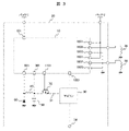
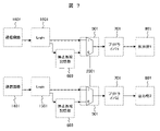
- the present invention provides a first terminal connected to a battery power supply, a switching power supply circuit for stepping down a battery voltage input from the first terminal, and a switching power supply circuit different from the battery power supply. It is characterized by comprising a second terminal connected to a power supply, a regulator circuit for stepping down a voltage input from the second terminal, and a pre-driver circuit connected to the regulator circuit.
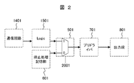
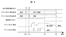
- the selection signal 2001 is the voltage of the first terminal 101, for example.
- a control device 20 for a transmission will be described as an example of a control device using the semiconductor device 10 of this embodiment.
Landscapes
- Engineering & Computer Science (AREA)
- Power Engineering (AREA)
- Physics & Mathematics (AREA)
- Electromagnetism (AREA)
- General Engineering & Computer Science (AREA)
- Mechanical Engineering (AREA)
- General Physics & Mathematics (AREA)
- Theoretical Computer Science (AREA)
- Radar, Positioning & Navigation (AREA)
- Automation & Control Theory (AREA)
- Continuous-Control Power Sources That Use Transistors (AREA)
- Control Of Transmission Device (AREA)
- Power Sources (AREA)
- Dc-Dc Converters (AREA)
Abstract
Description
Claims (12)
- バッテリ電源に接続される第1の端子と、
前記第1の端子から入力されるバッテリ電圧を降圧するスイッチング電源回路と、
前記バッテリ電源とは異なるスイッチング電源に接続される第2の端子と、
前記第2の端子から入力される電圧を降圧するレギュレータ回路と、
前記レギュレータ回路に接続されるプリドライバ回路と、
を備える半導体装置。 - 請求項1に記載の半導体装置であって、
通常動作時における各ブロックの設定値の保持および通信回路を介した外部からの入力信号の前記各ブロックへの分配を行うロジック回路と、
異常発生時の停止処理フローを記憶する停止処理記憶部と、
外部からの選択信号により前記ロジック回路と前記停止処理記憶部のいずれか一方を前記プリドライバ回路と接続する選択回路と、を有し、
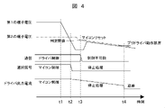
前記選択回路は、前記第1の端子の電圧が所定の電圧を下回った場合に、前記停止処理記憶部に予め記憶させた停止処理フローに基づき前記プリドライバ回路を停止させる半導体装置。 - 請求項1に記載の半導体装置であって、
前記スイッチング電源は、インダクタンス素子とダイオードとキャパシタとを有する半導体装置。 - 請求項1に記載の半導体装置であって、
前記第1の端子の電圧が所定の電圧を下回った場合に、当該半導体装置を制御するマイコンへの電源供給を停止する停止信号を出力する半導体装置。 - 請求項2に記載の半導体装置であって、
前記停止処理記憶部に記憶された停止処理フローは、前記通信回路を介した外部からの入力信号により書き換え可能である半導体装置。 - 請求項2に記載の半導体装置であって、
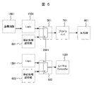
前記レギュレータ回路とは異なる別のレギュレータ回路と、
前記選択回路とは異なる別の選択回路と、
前記停止処理記憶部とは異なる停止処理記憶部と、を有し、
前記別の選択回路は、前記第1の端子の電圧が所定の電圧を下回った場合に、前記別の停止処理記憶部に予め記憶させた停止処理フローに基づき前記別のレギュレータ回路を停止させる半導体装置。 - 請求項1に記載の半導体装置であって、
出力トランジスタをさらに備え、
前記プリドライバ回路は、前記出力トランジスタを制御して、1つの電圧設定で絶対値の等しい正負両電圧を出力するトラッキングレギュレータである半導体装置。 - 請求項1に記載の半導体装置であって、
前記プリドライバ回路は、外付けの出力トランジスタを駆動制御する駆動回路である半導体装置。 - 請求項1から8のいずれか1項に記載の半導体装置を用いた変速機の制御装置であって、
前記プリドライバ回路により前記変速機の電磁コイルを駆動制御する変速機の制御装置。 - スイッチング電源回路とドライバ回路を混載する半導体装置を搭載した電子制御装置の制御方法であって、
前記ドライバ回路は、前記スイッチング電源回路の出力電力により制御される電子制御装置の制御方法。 - 請求項10に記載の電子制御装置の制御方法であって、
前記スイッチング電源回路の入力電圧が所定の電圧を下回った場合に、停止処理記憶部に予め記憶させた停止処理フローに基づき前記ドライバ回路を停止させる電子制御装置の制御方法。 - 請求項11に記載の電子制御装置の制御方法であって、
前記ドライバ回路は、変速機の電磁コイルを駆動制御する電子制御装置の制御方法。
Priority Applications (3)
| Application Number | Priority Date | Filing Date | Title |
|---|---|---|---|
| US18/279,421 US12462960B2 (en) | 2021-03-30 | 2021-09-10 | Semiconductor device, control device for transmission, and control method of electronic control unit |
| CN202180095491.0A CN116982017A (zh) | 2021-03-30 | 2021-09-10 | 半导体装置、变速器的控制装置、电子控制装置的控制方法 |
| JP2023510187A JP7498852B2 (ja) | 2021-03-30 | 2021-09-10 | 半導体装置、変速機の制御装置、電子制御装置の制御方法 |
Applications Claiming Priority (2)
| Application Number | Priority Date | Filing Date | Title |
|---|---|---|---|
| JP2021057067 | 2021-03-30 | ||
| JP2021-057067 | 2021-03-30 |
Publications (1)
| Publication Number | Publication Date |
|---|---|
| WO2022208933A1 true WO2022208933A1 (ja) | 2022-10-06 |
Family
ID=83457358
Family Applications (1)
| Application Number | Title | Priority Date | Filing Date |
|---|---|---|---|
| PCT/JP2021/033310 Ceased WO2022208933A1 (ja) | 2021-03-30 | 2021-09-10 | 半導体装置、変速機の制御装置、電子制御装置の制御方法 |
Country Status (4)
| Country | Link |
|---|---|
| US (1) | US12462960B2 (ja) |
| JP (1) | JP7498852B2 (ja) |
| CN (1) | CN116982017A (ja) |
| WO (1) | WO2022208933A1 (ja) |
Citations (3)
| Publication number | Priority date | Publication date | Assignee | Title |
|---|---|---|---|---|
| JP2001245489A (ja) * | 2000-02-29 | 2001-09-07 | Nippon Densan Corp | 車載用モータの制御装置 |
| JP2013156874A (ja) * | 2012-01-31 | 2013-08-15 | Fujitsu Ten Ltd | 電源回路 |
| WO2020179250A1 (ja) * | 2019-03-01 | 2020-09-10 | 日立オートモティブシステムズ株式会社 | 半導体集積回路 |
Family Cites Families (8)
| Publication number | Priority date | Publication date | Assignee | Title |
|---|---|---|---|---|
| JPH05344726A (ja) * | 1992-06-09 | 1993-12-24 | Kofu Nippon Denki Kk | スイッチング電源回路 |
| JP3470695B2 (ja) * | 2000-11-15 | 2003-11-25 | 株式会社村田製作所 | スイッチング電源装置およびそれを用いた電子装置 |
| US20050237037A1 (en) * | 2004-04-23 | 2005-10-27 | Intersil Americas Inc. | Switching power supply controller system and method |
| JP2009015380A (ja) | 2007-06-29 | 2009-01-22 | Fujitsu Ten Ltd | 電源装置及び電子制御装置 |
| JP5885589B2 (ja) * | 2012-05-28 | 2016-03-15 | ルネサスエレクトロニクス株式会社 | 半導体集積回路およびその動作方法 |
| JP5971074B2 (ja) * | 2012-10-15 | 2016-08-17 | 富士電機株式会社 | スイッチング電源装置 |
| JP6466761B2 (ja) * | 2015-03-31 | 2019-02-06 | ラピスセミコンダクタ株式会社 | 半導体装置、及び電源供給方法 |
| JP2022151261A (ja) * | 2021-03-26 | 2022-10-07 | セイコーエプソン株式会社 | 電源制御装置およびスイッチング電源装置 |
-
2021
- 2021-09-10 JP JP2023510187A patent/JP7498852B2/ja active Active
- 2021-09-10 CN CN202180095491.0A patent/CN116982017A/zh active Pending
- 2021-09-10 WO PCT/JP2021/033310 patent/WO2022208933A1/ja not_active Ceased
- 2021-09-10 US US18/279,421 patent/US12462960B2/en active Active
Patent Citations (3)
| Publication number | Priority date | Publication date | Assignee | Title |
|---|---|---|---|---|
| JP2001245489A (ja) * | 2000-02-29 | 2001-09-07 | Nippon Densan Corp | 車載用モータの制御装置 |
| JP2013156874A (ja) * | 2012-01-31 | 2013-08-15 | Fujitsu Ten Ltd | 電源回路 |
| WO2020179250A1 (ja) * | 2019-03-01 | 2020-09-10 | 日立オートモティブシステムズ株式会社 | 半導体集積回路 |
Also Published As
| Publication number | Publication date |
|---|---|
| CN116982017A (zh) | 2023-10-31 |
| US12462960B2 (en) | 2025-11-04 |
| US20240186046A1 (en) | 2024-06-06 |
| JPWO2022208933A1 (ja) | 2022-10-06 |
| JP7498852B2 (ja) | 2024-06-12 |
Similar Documents
| Publication | Publication Date | Title |
|---|---|---|
| US20170019097A1 (en) | Semiconductor switching device | |
| US7606015B2 (en) | Power semiconductor device architecture for output transistor protection | |
| US8564359B2 (en) | Method and system for controlling HS-NMOS power switches with slew-rate limitation | |
| US6362665B1 (en) | Backwards drivable MOS output driver | |
| JP2001051730A (ja) | スイッチ回路及びシリーズレギュレータ | |
| JP6785736B2 (ja) | 電圧調整器の出力のアンダーシュートを低減する電子回路 | |
| JP7388317B2 (ja) | 駆動回路およびインバータ装置 | |
| JP2012109937A (ja) | 電力用半導体装置及びその動作方法 | |
| US20200044635A1 (en) | Miller clamp driver with feedback bias control | |
| US6075391A (en) | Turn-off circuit for an LDMOS in presence of a reverse current | |
| US20080272754A1 (en) | Constant voltage power supply circuit and method of controlling the same | |
| JP2007201723A (ja) | 電力供給制御装置 | |
| US6781458B2 (en) | Providing DC isolation in switching amplifiers | |
| CN115149795A (zh) | 用于调节电压的电路布置、对应的系统和方法 | |
| US10268221B2 (en) | Power supply device and electronic control unit for lowering a minimum operating voltage and suppressing a consumed current to be low | |
| JP7498852B2 (ja) | 半導体装置、変速機の制御装置、電子制御装置の制御方法 | |
| JP3643298B2 (ja) | 出力回路 | |
| US11466650B2 (en) | Fuel injection valve driving device | |
| KR101323896B1 (ko) | 시스템의 전원공급제어장치 및 방법 | |
| US20030098619A1 (en) | Power supply circuit for actuator of on-board travel control device | |
| US7994759B2 (en) | System and method for driving a power supply device in an initial activation stage | |
| JPH04354106A (ja) | ソレノイド駆動回路と車輌搭載用at制御装置 | |
| JP2008259182A (ja) | 昇圧回路に用いられる電流制御回路 | |
| US6304112B1 (en) | Integrated circuit provided with a fail-safe mode | |
| KR101038212B1 (ko) | 액츄에이터 구동장치 |
Legal Events
| Date | Code | Title | Description |
|---|---|---|---|
| 121 | Ep: the epo has been informed by wipo that ep was designated in this application |
Ref document number: 21935092 Country of ref document: EP Kind code of ref document: A1 |
|
| ENP | Entry into the national phase |
Ref document number: 2023510187 Country of ref document: JP Kind code of ref document: A |
|
| WWE | Wipo information: entry into national phase |
Ref document number: 18279421 Country of ref document: US |
|
| WWE | Wipo information: entry into national phase |
Ref document number: 202180095491.0 Country of ref document: CN |
|
| NENP | Non-entry into the national phase |
Ref country code: DE |
|
| 122 | Ep: pct application non-entry in european phase |
Ref document number: 21935092 Country of ref document: EP Kind code of ref document: A1 |
|
| WWG | Wipo information: grant in national office |
Ref document number: 18279421 Country of ref document: US |