WO2022202788A1 - エレメント、摩擦エレメント接合方法および摩擦エレメント接合継手の製造方法 - Google Patents
エレメント、摩擦エレメント接合方法および摩擦エレメント接合継手の製造方法 Download PDFInfo
- Publication number
- WO2022202788A1 WO2022202788A1 PCT/JP2022/013081 JP2022013081W WO2022202788A1 WO 2022202788 A1 WO2022202788 A1 WO 2022202788A1 JP 2022013081 W JP2022013081 W JP 2022013081W WO 2022202788 A1 WO2022202788 A1 WO 2022202788A1
- Authority
- WO
- WIPO (PCT)
- Prior art keywords
- plate
- mandrel
- press
- joining
- pin
- Prior art date
Links
- 238000000034 method Methods 0.000 title claims description 19
- 238000004519 manufacturing process Methods 0.000 title claims description 8
- 238000003466 welding Methods 0.000 title abstract description 13
- 229910052751 metal Inorganic materials 0.000 claims abstract description 97
- 239000002184 metal Substances 0.000 claims abstract description 97
- 238000005520 cutting process Methods 0.000 claims abstract description 18
- 238000005304 joining Methods 0.000 claims description 48
- 229910000831 Steel Inorganic materials 0.000 claims description 30
- 239000010959 steel Substances 0.000 claims description 30
- 239000000463 material Substances 0.000 claims description 10
- 230000002093 peripheral effect Effects 0.000 claims description 8
- 239000011248 coating agent Substances 0.000 claims description 3
- 238000000576 coating method Methods 0.000 claims description 3
- 238000005516 engineering process Methods 0.000 description 7
- 229910000838 Al alloy Inorganic materials 0.000 description 5
- 238000007599 discharging Methods 0.000 description 4
- 239000012530 fluid Substances 0.000 description 3
- 239000000446 fuel Substances 0.000 description 3
- 230000004927 fusion Effects 0.000 description 3
- 230000035515 penetration Effects 0.000 description 3
- 238000003825 pressing Methods 0.000 description 3
- RYGMFSIKBFXOCR-UHFFFAOYSA-N Copper Chemical compound [Cu] RYGMFSIKBFXOCR-UHFFFAOYSA-N 0.000 description 2
- 229910052782 aluminium Inorganic materials 0.000 description 2
- 230000000052 comparative effect Effects 0.000 description 2
- 229910052802 copper Inorganic materials 0.000 description 2
- 239000010949 copper Substances 0.000 description 2
- 239000007769 metal material Substances 0.000 description 2
- 238000009864 tensile test Methods 0.000 description 2
- 241000282414 Homo sapiens Species 0.000 description 1
- ATJFFYVFTNAWJD-UHFFFAOYSA-N Tin Chemical compound [Sn] ATJFFYVFTNAWJD-UHFFFAOYSA-N 0.000 description 1
- XAGFODPZIPBFFR-UHFFFAOYSA-N aluminium Chemical compound [Al] XAGFODPZIPBFFR-UHFFFAOYSA-N 0.000 description 1
- 239000000919 ceramic Substances 0.000 description 1
- 238000004140 cleaning Methods 0.000 description 1
- 238000002485 combustion reaction Methods 0.000 description 1
- 238000007796 conventional method Methods 0.000 description 1
- 230000002950 deficient Effects 0.000 description 1
- 230000000694 effects Effects 0.000 description 1
- 230000007613 environmental effect Effects 0.000 description 1
- 238000002474 experimental method Methods 0.000 description 1
- 230000009969 flowable effect Effects 0.000 description 1
- 229910000765 intermetallic Inorganic materials 0.000 description 1
- 238000011835 investigation Methods 0.000 description 1
- 238000002844 melting Methods 0.000 description 1
- 230000008018 melting Effects 0.000 description 1
- 238000005555 metalworking Methods 0.000 description 1
- 238000005121 nitriding Methods 0.000 description 1
- 238000012545 processing Methods 0.000 description 1
- 238000011160 research Methods 0.000 description 1
- 230000000717 retained effect Effects 0.000 description 1
- 239000002344 surface layer Substances 0.000 description 1
- 238000012360 testing method Methods 0.000 description 1
- 238000010792 warming Methods 0.000 description 1
- 239000002699 waste material Substances 0.000 description 1
Images


Classifications
-
- B—PERFORMING OPERATIONS; TRANSPORTING
- B23—MACHINE TOOLS; METAL-WORKING NOT OTHERWISE PROVIDED FOR
- B23K—SOLDERING OR UNSOLDERING; WELDING; CLADDING OR PLATING BY SOLDERING OR WELDING; CUTTING BY APPLYING HEAT LOCALLY, e.g. FLAME CUTTING; WORKING BY LASER BEAM
- B23K20/00—Non-electric welding by applying impact or other pressure, with or without the application of heat, e.g. cladding or plating
- B23K20/12—Non-electric welding by applying impact or other pressure, with or without the application of heat, e.g. cladding or plating the heat being generated by friction; Friction welding
- B23K20/122—Non-electric welding by applying impact or other pressure, with or without the application of heat, e.g. cladding or plating the heat being generated by friction; Friction welding using a non-consumable tool, e.g. friction stir welding
- B23K20/1245—Non-electric welding by applying impact or other pressure, with or without the application of heat, e.g. cladding or plating the heat being generated by friction; Friction welding using a non-consumable tool, e.g. friction stir welding characterised by the apparatus
- B23K20/1255—Tools therefor, e.g. characterised by the shape of the probe
-
- B—PERFORMING OPERATIONS; TRANSPORTING
- B23—MACHINE TOOLS; METAL-WORKING NOT OTHERWISE PROVIDED FOR
- B23K—SOLDERING OR UNSOLDERING; WELDING; CLADDING OR PLATING BY SOLDERING OR WELDING; CUTTING BY APPLYING HEAT LOCALLY, e.g. FLAME CUTTING; WORKING BY LASER BEAM
- B23K20/00—Non-electric welding by applying impact or other pressure, with or without the application of heat, e.g. cladding or plating
- B23K20/12—Non-electric welding by applying impact or other pressure, with or without the application of heat, e.g. cladding or plating the heat being generated by friction; Friction welding
- B23K20/122—Non-electric welding by applying impact or other pressure, with or without the application of heat, e.g. cladding or plating the heat being generated by friction; Friction welding using a non-consumable tool, e.g. friction stir welding
- B23K20/1245—Non-electric welding by applying impact or other pressure, with or without the application of heat, e.g. cladding or plating the heat being generated by friction; Friction welding using a non-consumable tool, e.g. friction stir welding characterised by the apparatus
- B23K20/125—Rotary tool drive mechanism
-
- B—PERFORMING OPERATIONS; TRANSPORTING
- B23—MACHINE TOOLS; METAL-WORKING NOT OTHERWISE PROVIDED FOR
- B23K—SOLDERING OR UNSOLDERING; WELDING; CLADDING OR PLATING BY SOLDERING OR WELDING; CUTTING BY APPLYING HEAT LOCALLY, e.g. FLAME CUTTING; WORKING BY LASER BEAM
- B23K20/00—Non-electric welding by applying impact or other pressure, with or without the application of heat, e.g. cladding or plating
- B23K20/12—Non-electric welding by applying impact or other pressure, with or without the application of heat, e.g. cladding or plating the heat being generated by friction; Friction welding
- B23K20/129—Non-electric welding by applying impact or other pressure, with or without the application of heat, e.g. cladding or plating the heat being generated by friction; Friction welding specially adapted for particular articles or workpieces
-
- B—PERFORMING OPERATIONS; TRANSPORTING
- B23—MACHINE TOOLS; METAL-WORKING NOT OTHERWISE PROVIDED FOR
- B23K—SOLDERING OR UNSOLDERING; WELDING; CLADDING OR PLATING BY SOLDERING OR WELDING; CUTTING BY APPLYING HEAT LOCALLY, e.g. FLAME CUTTING; WORKING BY LASER BEAM
- B23K35/00—Rods, electrodes, materials, or media, for use in soldering, welding, or cutting
- B23K35/02—Rods, electrodes, materials, or media, for use in soldering, welding, or cutting characterised by mechanical features, e.g. shape
- B23K35/0255—Rods, electrodes, materials, or media, for use in soldering, welding, or cutting characterised by mechanical features, e.g. shape for use in welding
- B23K35/0288—Welding studs
-
- B—PERFORMING OPERATIONS; TRANSPORTING
- B23—MACHINE TOOLS; METAL-WORKING NOT OTHERWISE PROVIDED FOR
- B23K—SOLDERING OR UNSOLDERING; WELDING; CLADDING OR PLATING BY SOLDERING OR WELDING; CUTTING BY APPLYING HEAT LOCALLY, e.g. FLAME CUTTING; WORKING BY LASER BEAM
- B23K2101/00—Articles made by soldering, welding or cutting
- B23K2101/18—Sheet panels
Definitions
- the present invention relates to friction element welding called FEW (Friction Element Welding), and particularly metal plates such as steel plates (for example, ordinary steel plates, high-tensile steel plates, etc.) and light metal plates (for example, aluminum plates, aluminum alloy plates, copper plates, etc.).
- FEW Frition Element Welding
- metal plates such as steel plates (for example, ordinary steel plates, high-tensile steel plates, etc.) and light metal plates (for example, aluminum plates, aluminum alloy plates, copper plates, etc.).
- the present invention relates to an element suitable for friction element joining in which two or more of the above are overlapped and joined, a friction element joining method using the same, and a method of manufacturing a friction element joined joint.
- Non-Patent Document 1 discloses a technique of performing frictional element joining using metal joining parts (hereinafter referred to as elements).
- elements metal joining parts
- metal plates are superimposed to form a plate assembly, and the elements are rotated at high speed and pressurized to force the elements to enter the plate assembly (hereinafter referred to as press-fitting) for joining.
- Patent Document 1 discloses a connecting element for friction welding connection.
- the element comprises a cylindrical mandrel, a collar attached to the mandrel and a pin projecting as a centering part from the substantially flat end face of the mandrel facing away from the collar. It is preferred that the mandrel surround the centering portion and have a recess for receiving softened material extruded from the centering portion, and that the pin be cylindrical or conical.
- the apex of the pin when the element is press-fitted into the plate assembly, the apex of the pin first contacts the plate assembly and rotates at high speed while being held in that position, thereby dissipating a predetermined amount of frictional heat. It is said that it can be generated by concentrating on the position of
- the position of the central axis of the pin tends to fluctuate greatly during the stage of generating frictional heat by rotating the element at high speed while bringing the apex of the pin into contact with the upper plate, and the frictional heat is generated. Because it is dispersed and not concentrated in a predetermined position on the upper plate, the upper plate does not soften easily, and as a result, the mandrel of the element does not penetrate the upper plate, and the penetration capability is insufficient, making it difficult to join the plate assembly. I have found that there is a problem. In particular, this phenomenon is conspicuous when it is applied to a set of plates in which steel plates are arranged not only on the lower plate but also on the upper plate.
- An object of the present invention is to solve the above-described problems of the conventional technology and to provide an element suitable for friction element joining of a plate assembly in which two or more metal plates are superimposed.
- the present inventors diligently studied elements that can be applied to friction element joining of a set of two metal plates in which metal plates are arranged on both the lower plate and the upper plate.
- the upper plate of the plate assembly consisting of two metal plates is the metal plate on the side that the apex of the pin first contacts before the mandrel of the element is press-fitted into the plate assembly.
- the apex of the pin rotating at high speed abuts against the upper plate, and as the pin is further pressed into the upper plate, an amount of metal plate (upper plate) corresponding to the volume of the pin press-fitted inside the upper plate is shaved off.
- the machined metal plate (shavings) can be discharged smoothly, the pin can be press-fitted into the upper plate while the pin is held at a predetermined position, and the lower end face of the mandrel contacts the upper plate.
- the element can continue to rotate at high speed without changing its position, the generated frictional heat is concentrated, and the position where the frictional heat is concentrated is softened and plastic flow is likely to occur.
- the softened and flowable metal that is, the upper plate
- the mandrel can be press-fitted into the upper plate and penetrated therethrough.
- a groove for discharging chips that have been cut from the upper plate by the pins that constitute the element, and for discharging metal that can flow due to plastic flow of the upper plate (hereinafter referred to as "fluid metal”)
- fluid metal a groove for discharging chips that have been cut from the upper plate by the pins that constitute the element, and for discharging metal that can flow due to plastic flow of the upper plate
- the lower end surface of the mandrel is a conical surface having an apex angle ⁇ m, and a groove for discharging cutting chips (cutting waste discharge groove) or a cutting edge is provided on the conical surface. Therefore, the inventors realized that it is possible to more smoothly perform friction element joining of a plate assembly in which various steel plates are combined.
- the present invention was completed based on these findings and further studies. That is, the gist of the present invention is as follows. [1] An element for performing frictional element joining of a plate set in which two or more metal plates are superimposed and press-fitted into the plate set while being rotated, A cylindrical mandrel to be press-fitted into the plate assembly in the friction element joining, a disk-shaped collar disposed on the upper end surface of the mandrel, and a lower end surface of the mandrel having a central axis that coincides with the central axis of the mandrel.
- An element for performing frictional element joining of a plate set in which two or more metal plates are superimposed and press-fitted into the plate set while being rotated A cylindrical mandrel to be press-fitted into the plate set in the friction element joining, a disk-shaped collar disposed on the upper end surface of the mandrel, and a lower end surface of the mandrel having a conical shape with an apex angle ⁇ m.
- T TOTAL - T BOTTOM total thickness of board assembly (mm)
- T BOTTOM board thickness of lower board of board assembly (mm)
- T TOTAL total thickness of board assembly (mm)
- T BOTTOM board thickness of lower board of board assembly (mm)
- friction element joining can be applied to a plate set in which two metal plates are superimposed as a lower plate and an upper plate. Frictional element joining can also be applied to a plate assembly in which steel plates are superimposed, or a plate assembly in which two steel plates are used as a lower plate and an upper plate, and one or more light metal plates are sandwiched between them. Effective.
- FIG. 4 is an explanatory view schematically showing another example of the element of the present invention, (a) being a side view of a mandrel and (b) being a plan view of the mandrel.
- FIG. 2 is a cross-sectional view schematically showing an example of a plate assembly that is joined using the elements shown in FIG. It is a stack of boards. 1.
- It is sectional drawing which shows typically the example which joins a board group using the element shown in FIG. 1, (a) is an example before press-fitting an element, (b) is an example after press-fitting an element.
- the element 1 of the present invention comprises a cylindrical mandrel 2 which is press-fitted into the plate assembly when performing friction element joining of the plate assembly, and one end surface of the mandrel 2 (hereinafter referred to as the upper end surface). ) and a conical pin 4 disposed on the other end face (hereinafter referred to as the lower end face) of the mandrel 2 .
- the diameter of the collar 3 is larger than the diameter of the mandrel 2, and the outer peripheral portion of the collar 3 is arranged to protrude from the outer periphery of the mandrel 2.
- the outer peripheral portion of the collar 3 is preferably formed so as to be inclined or curved downward.
- the diameter of the bottom surface of the pin 4 (the surface in contact with the lower end surface of the mandrel 2) is smaller than the diameter of the mandrel 2. Also, the pin 4 is arranged so that its central axis (that is, the center of the bottom surface) coincides with the central axis of the mandrel 2 . Therefore, the lower end surface of the mandrel 2 excluding the pin 4 becomes a flat area (portion).
- a fluidized metal discharge groove 5 is formed in a spiral or radial shape in a flat area (site) adjacent to the pin 4 .
- the number of fluidized metal discharge grooves 5 is preferably two or more.
- the number of fluidized metal discharge grooves 5 is preferably 10 or less. It is more preferable to set the number to 6 or less.
- the width W (mm) of the fluidized metal discharge groove 5 is preferably 0.01 mm or more. More preferably, the width W of the fluidized metal discharge groove 5 is 0.5 mm or more.
- the width W of the fluidized metal discharge groove 5 is 3 mm or less. More preferably, the width W of the fluidized metal discharge groove 5 is 1 mm or less.
- the depth U of the fluidized metal discharge groove 5 is preferably 0.01 mm or more. More preferably, the depth U of the fluidized metal discharge groove 5 is 0.5 mm or more.
- the depth U of the fluidized metal discharge groove 5 is preferably 3 mm or less. More preferably, the depth U of the fluidized metal discharge groove 5 is 2 mm or less.
- the number, width W, and depth U of the fluidized metal discharge grooves 5 in this way, it is possible to press-fit the element 1 into the plate group while smoothly discharging chips and fluidized metal. .
- the area of the portion forming the flowing metal discharge groove 5 that is, the area of the flat region of the lower end surface of the mandrel 2 excluding the pin 4
- the press-fitting of the element 1 is hindered. Therefore, the area of the bottom surface of the pin 4 is adjusted by specifying the apex angle ⁇ and the height H of the pin 4 .
- the apex angle ⁇ of the pin 4 is 30° or more. It is more preferable that the apex angle ⁇ of the pin 4 is 120° or more.
- the apex angle ⁇ of the pin 4 is preferably in the range of less than 180°. The apex angle ⁇ of the pin 4 is more preferably 160° or less.
- the height H of the pin 4 is preferably 0.01 mm or more. More preferably, the height H of the pin 4 is 0.1 mm or more.
- the height H of the pin 4 is 3 mm or less. More preferably, the height H of the pin 4 is 1 mm or less.
- the friction element joining can be performed efficiently by increasing the wear resistance of the pin 4 and the mandrel 2. Therefore, at least the outer surface of the pin 4 and the lower end surface of the mandrel 2 are preferably coated with a wear-resistant material.
- the wear-resistant material may have desired performance, and is not particularly specified, but may be subjected to hardening treatment such as WC, TiN, other ceramics, heat-resistant steel, nitriding, and the like.
- the element 1 shown in FIG. 2 has the form of a twist drill for metalworking, in which a pair of cutting edges formed by the tip angle of a mandrel 2 has a ridgeline shape curved from the tip toward the outer peripheral edge. , at the lower end of the mandrel 2 . That is, the lower end face is a conical surface with a vertex angle of ⁇ m, and one or more pairs of chip discharge grooves 11 are arranged in a curved line from the apex on the conical surface. A cutting edge 10 is formed adjacent to the groove 11 .
- the conical surface may be provided with only the chip discharge groove 11 and the cutting edge 10 may not be formed.
- the chip discharge groove 11 may be arranged radially from the vertex instead of curved. As shown in FIG. 2(b), the cutting edge 10 may be curved, but a straight line is more advantageous for adjustment of the cutting edge.
- the apex angle ⁇ m is preferably 30° or more.
- the apex angle ⁇ m is more preferably 120° or more.
- the apex angle ⁇ m is preferably in the range of less than 180°.
- the apex angle ⁇ m is more preferably 160° or less.
- FIG. 3(a) is a cross-sectional view of a plate set in which two metal plates are superimposed
- FIG. 3(b) is a cross-sectional view of a plate set in which three metal plates are superimposed.
- the element 1 uses the example shown in FIG. In FIG. 3, illustration of the fluidized metal discharge groove 5, the cutting edge 10, and the chip discharge groove 11 of the element 1 is omitted.
- the plate set 6 shown in FIG. 3(a) is a plate set 6 in which two metal plates consisting of an upper plate 7 and a lower plate 8 are superimposed.
- the plate set 6 shown in FIG. 3B is a plate set 6 made up of a total of three metal plates in which one metal plate is sandwiched between the upper plate 7 and the lower plate 8 .
- the present invention can also be applied to a plate set (not shown) composed of a total of four or more metal plates in which two or more metal plates are sandwiched between the upper plate 7 and the lower plate 8 .
- the pin 4 and the mandrel 2, or the mandrel 2 are softened by frictional heat to cause plastic flow, and are then discharged through the fluidized metal discharge groove 5 or the chip discharge groove 11. Therefore, if the distance L is too small (for example, distance L ⁇ (T TOTAL ⁇ T BOTTOM )+0.02 mm), the problem arises that the lower plate 8 cannot be reached.
- the distance L (mm) from the bottom edge of the outer circumference of the collar 3 to the top of the pin 4 is the total thickness T TOTAL (mm) of the plate set 6 and the plate thickness T BOTTOM (mm) of the lower plate 8. It is preferable to use a mandrel set at a difference of (T TOTAL ⁇ T BOTTOM )+0.02 mm or more.
- the above distance L (mm) shall be the difference between the total thickness T TOTAL (mm) of the plate group 6 and the plate thickness T BOTTOM (mm) of the lower plate 8 (T TOTAL - T BOTTOM ) + 0.2 mm or more.
- the distance L is the length in the direction parallel to the central axis of the mandrel 2 . This allows the pin 4 to reach the lower plate 8 by press-fitting the element 1 from above the upper plate 7 in frictional element joining. On the other hand, if the distance L is too large, the mandrel 2 deforms (for example, bends, twists, or buckles) above the top plate 7 (that is, before it is pressed into the top plate 7) when the element 1 is press-fitted.
- the distance L (mm) preferably satisfies (T TOTAL ⁇ T BOTTOM )+4 mm or less.
- the distance L (mm) is more preferably (T TOTAL ⁇ T BOTTOM )+2 mm or less, more preferably (T TOTAL ⁇ T BOTTOM )+1.5 mm or less. Note that the distance L (mm) in the direction parallel to the central axis from the lowest end of the outer peripheral portion of the collar to the vertex of the lower end surface of the mandrel shown in FIG. is preferred.
- FIG. 4 is a cross-sectional view schematically showing a case where the plate assembly 6 is joined using the element 1 (see FIG. 3(a)).
- FIG. 4(b) shows the state after the element 1 is press-fitted into the plate group 6.
- illustration of the fluidized metal discharge groove 5 of the element 1, the cutting edge 10, the chip discharge groove 11, and the rotary pressure machine for pressing the element 1 into the plate assembly 6 is omitted.
- the element 1 When the element 1 is press-fitted into the plate set 6, the element 1 rotating at high speed descends from above the upper plate 7, and the top of the pin 4 comes into contact with the upper plate 7 (see FIG. 4(a)). At this time, the central axis of the pin 4 (that is, the central axis of the mandrel 2) is perpendicular to the upper plate 7. As shown in FIG. As the element 1 continues to descend while rotating at high speed, the pin 4 is gradually press-fitted into the upper plate 7 from the top, and the central axis of the pin 4 is held at a predetermined position as the rotation axis of the element 1.
- the upper plate 7 discharged from the fluidized metal discharge groove 5 and the chip discharge groove 11 moves upward along the side surface of the mandrel 2 .
- the reason for this is that the lower plate 8 is arranged below and hinders movement.
- the top plate 7 is constrained by the outer circumference of the collar 3 after it has moved and protruded into the free space above, and is thus fixed to the element 1 . That is, when the element 1 of the present invention is used for friction element joining of a plate assembly 6 in which two metal plates are superimposed as shown in FIG. Joined at face 9 , top plate 7 is fixed to mandrel 2 and collar 3 .
- the type of metal plates to be superimposed as the plate set 6 is not particularly limited. Frictional heat is generated and the joint surfaces 9 are firmly joined.
- the element 1 of the present invention has the fluidized metal discharge groove 5 and the chip discharge groove 11, chip chips and softened top plate 7 can be discharged smoothly. Therefore, friction element joining of the plate set 6 in which steel plates are arranged not only on the lower plate 8 but also on the upper plate 7 can be performed without any trouble, and a friction element joined joint in which the plate set 6 is firmly joined can be obtained.
- the element targeted by the present invention is a plate assembly consisting of two metal plates in which a steel plate is arranged as a lower plate and a light metal plate is arranged as an upper plate, or a plate assembly in which both the lower plate and the upper plate are both steel plates, Alternatively, it can also be applied to friction element joining of a plate set consisting of three or more metal plates in which one or more light metal plates are sandwiched between a steel plate as a lower plate and a light metal plate as an upper plate without any problem, resulting in poor joining. can be obtained.
- Example 1 A plate set in which two metal plates (an upper plate and a lower plate) are superimposed is joined by friction element joining to prepare two friction element joined joints each.
- the element 1 used has the shape shown in FIG. 1, has an apex angle ⁇ of 140°, and has two flowing metal discharge grooves 5 arranged in a spiral.
- Mandrel 2 had a diameter of 4.55 mm.
- Table 1 shows the combination of the upper plate and the lower plate
- Table 2 shows the rotational speed (rpm) and applied pressure (kN) of the element used when joining the friction elements.
- rpm rotational speed
- KN applied pressure
- the joints evaluated as good ( ⁇ ) in the joint state were subjected to a cross tension test specified in JIS Z 3137 to investigate the strength of the joints.
- the strength was evaluated as A when the strength was 6.0 kN or more, B when the strength was 3.0 kN or more and less than 6.0 kN, and C when the strength was less than 3.0 kN.
- the joint state was good, and when both the upper plate and the lower plate were steel plates, the joint strength was 2.8 kN or more.
- joint No. In No. 12 the joint state is good "O", but since the upper plate is an aluminum alloy plate, the strength of the base material is lower than when the upper plate is a steel plate, and the strength as a joint joint is 1.0 kN. It is speculated that the value was relatively low.
- the bonding state was poor "x".
- Example 2 Two metal plates (upper plate and lower plate) shown in Table 1 were superimposed on each other and joined by friction element joining to prepare two friction element joints.
- the element 1 used was the element 1 having the shape shown in FIG.
- the element has an apex angle ⁇ m of 140° and a mandrel having two cutting blades 10 and a pair of chip discharge grooves 11 arranged in a curved line from the apex on the conical bottom surface.
- Mandrel 2 had a diameter of 4.55 mm.
- Table 3 shows the rotational speed (rpm) and applied pressure (kN) of the element used when joining the friction elements. For comparison, frictional element joining was also performed using the element 1 without the chip discharge groove 11 and the cutting edge 10 .
- Example 1 Regarding the obtained friction element welded joint, the cross section of the welded portion was visually observed in the same manner as in Example 1, and the welded state of the plate assembly was evaluated in the same manner as in Example 1.
- the bonding state was good, and when both the upper and lower plates were steel plates, they had a tensile strength of 2.1 kN or more.
- joint No. In No. 25 the joint state is good "O", but since the upper plate is an aluminum alloy plate, the wear of the element during penetration into the upper plate is remarkable, and a sufficient joint diameter cannot be secured, and the joint strength is 1. It was 5 kN, which was a lower value than the above.
- the bonding state was poor "x".
Landscapes
- Engineering & Computer Science (AREA)
- Mechanical Engineering (AREA)
- Pressure Welding/Diffusion-Bonding (AREA)
Abstract
Description
[1] 2枚以上の金属板を重ね合わせた板組に回転させながら圧入することによって前記板組の摩擦エレメント接合を行なうエレメントであって、
前記摩擦エレメント接合において前記板組に圧入する円柱形状のマンドレルと、該マンドレルの上端面に配設される円板状のカラーと、前記マンドレルの下端面に、中心軸が前記マンドレルの中心軸と一致するように配設される頂角αの円錐形状のピンとを備え、かつ前記マンドレルの前記下端面の前記ピンを除く平坦な領域に、流動金属排出溝を渦状または放射線状に複数本形成してなるエレメント。
[2] 2枚以上の金属板を重ね合わせた板組に回転させながら圧入することによって前記板組の摩擦エレメント接合を行なうエレメントであって、
前記摩擦エレメント接合において前記板組に圧入する円柱形状のマンドレルと、該マンドレルの上端面に配設される円板状のカラーと、を備え、さらに前記マンドレルの下端面を頂角αmの円錐状を呈する面とし、かつ該円錐状を呈する面に、切削屑排出溝を頂点から曲線状または放射線状に一対以上、あるいはさらに切削刃を複数本形成してなるエレメント。
[3] カラーの外周部の最下端からピンの頂点までの前記中心軸に平行な方向の距離L(mm)が、下記(1)式を満たす[1]に記載のエレメント。
記
(TTOTAL-TBOTTOM)+0.02mm≦L≦(TTOTAL-TBOTTOM)+4mm・・・(1)
ここで、TTOTAL:板組の全厚(mm)、TBOTTOM:板組の下板の板厚(mm)
[4] カラーの外周部の最下端からマンドレルの下端面の頂点までの中心軸に平行な方向の距離L(mm)が、下記(1)式を満たす[2]に記載のエレメント。
記
(TTOTAL-TBOTTOM)+0.02mm≦L≦(TTOTAL-TBOTTOM)+4mm・・・(1)
ここで、TTOTAL:板組の全厚(mm)、TBOTTOM:板組の下板の板厚(mm)
[5] エレメントが、少なくとも外表面の一部に耐摩耗性材料からなるコーティング被膜を形成してなる[1]~[4]のいずれかに記載のエレメント。
[6] [1]~[5]のいずれかに記載のエレメントを用いて、2枚以上の金属板を重ね合わせた板組にエレメントを回転させながら圧入することによって板組の接合を行なう摩擦エレメント接合方法。
[7] 2枚以上の金属板を重ね合わせた板組が、下板および上板の両方に鋼板を配置した板組である[6]に記載の摩擦エレメント接合方法。
[8] [1]~[5]のいずれかに記載のエレメントを用いて、2枚以上の金属板を重ね合わせた板組にエレメントを回転させながら圧入し板組の接合を行ない摩擦エレメント接合継手とする摩擦エレメント接合継手の製造方法。
[9] 2枚以上の金属板を重ね合わせた板組が、下板および上板の両方に鋼板を配置した板組である[8]に記載の摩擦エレメント接合継手の製造方法。
2枚(上板と下板)の金属板を重ね合わせた板組の摩擦エレメント接合を行ない、摩擦エレメント接合継手を各2個作製した。なお、使用したエレメント1は、図1に示す形状のエレメント1とし、頂角αが140°、流動金属排出溝5が2本を渦状に配置されたエレメントとした。マンドレル2の直径は4.55mmであった。

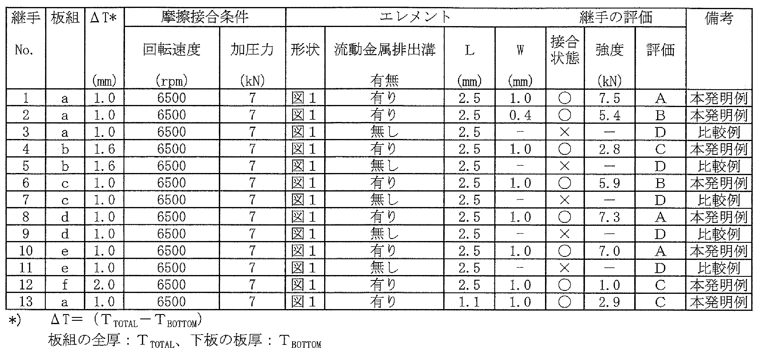
表1に示す2枚(上板と下板)の金属板を重ね合わせた板組の摩擦エレメント接合を行ない、摩擦エレメント接合継手を各2個作製した。なお、使用したエレメント1は、図2に示す形状のエレメント1とし、カラー3の最下端部からマンドレル2の下端面の頂点までの距離Lが1~5mm、下端面の円錐状を呈する面の頂角αmが140°、下端面の円錐状を呈する面に、切削屑排出溝11を頂点から曲線状に一対配置し、さらに切削刃10を2本形成したマンドレルを配置したエレメントとした。マンドレル2の直径は4.55mmであった。

2 マンドレル
3 カラー
4 ピン
5 流動金属排出溝
6 板組
7 上板
8 下板
9 接合面
10 切削刃
11 切削屑排出溝(屑排出溝)
12 開口部
Claims (9)
- 2枚以上の金属板を重ね合わせた板組に回転させながら圧入することによって前記板組の摩擦エレメント接合を行なうエレメントであって、
前記摩擦エレメント接合において前記板組に圧入する円柱形状のマンドレルと、該マンドレルの上端面に配設される円板状のカラーと、前記マンドレルの下端面に、中心軸が前記マンドレルの中心軸と一致するように配設される頂角αの円錐形状のピンとを備え、かつ前記マンドレルの前記下端面の前記ピンを除く平坦な領域に、流動金属排出溝を渦状または放射線状に複数本形成してなるエレメント。 - 2枚以上の金属板を重ね合わせた板組に回転させながら圧入することによって前記板組の摩擦エレメント接合を行なうエレメントであって、
前記摩擦エレメント接合において前記板組に圧入する円柱形状のマンドレルと、該マンドレルの上端面に配設される円板状のカラーと、を備え、さらに前記マンドレルの下端面を頂角αmの円錐状を呈する面とし、かつ該円錐状を呈する面に、切削屑排出溝を頂点から曲線状または放射線状に一対以上、あるいはさらに切削刃を複数本形成してなるエレメント。 - カラーの外周部の最下端からピンの頂点までの前記中心軸に平行な方向の距離L(mm)が、下記(1)式を満たす請求項1に記載のエレメント。
記
(TTOTAL-TBOTTOM)+0.02mm≦L≦(TTOTAL-TBOTTOM)+4mm・・・(1)
ここで、TTOTAL:板組の全厚(mm)、TBOTTOM:板組の下板の板厚(mm) - カラーの外周部の最下端からマンドレルの下端面の頂点までの中心軸に平行な方向の距離L(mm)が、下記(1)式を満たす請求項2に記載のエレメント。
記
(TTOTAL-TBOTTOM)+0.02mm≦L≦(TTOTAL-TBOTTOM)+4mm・・・(1)
ここで、TTOTAL:板組の全厚(mm)、TBOTTOM:板組の下板の板厚(mm) - エレメントが、少なくとも外表面の一部に耐摩耗性材料からなるコーティング被膜を形成してなる請求項1~4のいずれかに記載のエレメント。
- 請求項1~5のいずれかに記載のエレメントを用いて、2枚以上の金属板を重ね合わせた板組にエレメントを回転させながら圧入することによって板組の接合を行なう摩擦エレメント接合方法。
- 2枚以上の金属板を重ね合わせた板組が、下板および上板の両方に鋼板を配置した板組である請求項6に記載の摩擦エレメント接合方法。
- 請求項1~5のいずれかに記載のエレメントを用いて、2枚以上の金属板を重ね合わせた板組にエレメントを回転させながら圧入し板組の接合を行ない摩擦エレメント接合継手とする摩擦エレメント接合継手の製造方法。
- 2枚以上の金属板を重ね合わせた板組が、下板および上板の両方に鋼板を配置した板組である請求項8に記載の摩擦エレメント接合継手の製造方法。
Priority Applications (6)
| Application Number | Priority Date | Filing Date | Title |
|---|---|---|---|
| KR1020237031222A KR20230142619A (ko) | 2021-03-24 | 2022-03-22 | 엘리먼트, 마찰 엘리먼트 접합 방법 및 마찰 엘리먼트 접합 조인트의 제조 방법 |
| JP2022536965A JP7332050B2 (ja) | 2021-03-24 | 2022-03-22 | エレメント、摩擦エレメント接合方法および摩擦エレメント接合継手の製造方法 |
| US18/282,359 US20240149372A1 (en) | 2021-03-24 | 2022-03-22 | Element, method of friction element welding, and method of manufacturing friction-element-welded joint |
| CN202280021109.6A CN116981532A (zh) | 2021-03-24 | 2022-03-22 | 元件、摩擦元件接合方法及摩擦元件接合接头的制造方法 |
| MX2023011048A MX2023011048A (es) | 2021-03-24 | 2022-03-22 | Elemento, metodo de soldadura de elementos de friccion y metodo de fabricacion de junta soldada de elementos de friccion. |
| EP22775571.7A EP4279209A4 (en) | 2021-03-24 | 2022-03-22 | ELEMENT, FRICTION ELEMENT WELDING PROCESS AND PROCESS FOR PRODUCING A FRICTION ELEMENT WELDING JOINT |
Applications Claiming Priority (2)
| Application Number | Priority Date | Filing Date | Title |
|---|---|---|---|
| JP2021050332 | 2021-03-24 | ||
| JP2021-050332 | 2021-03-24 |
Publications (1)
| Publication Number | Publication Date |
|---|---|
| WO2022202788A1 true WO2022202788A1 (ja) | 2022-09-29 |
Family
ID=83397255
Family Applications (1)
| Application Number | Title | Priority Date | Filing Date |
|---|---|---|---|
| PCT/JP2022/013081 WO2022202788A1 (ja) | 2021-03-24 | 2022-03-22 | エレメント、摩擦エレメント接合方法および摩擦エレメント接合継手の製造方法 |
Country Status (7)
| Country | Link |
|---|---|
| US (1) | US20240149372A1 (ja) |
| EP (1) | EP4279209A4 (ja) |
| JP (1) | JP7332050B2 (ja) |
| KR (1) | KR20230142619A (ja) |
| CN (1) | CN116981532A (ja) |
| MX (1) | MX2023011048A (ja) |
| WO (1) | WO2022202788A1 (ja) |
Citations (5)
| Publication number | Priority date | Publication date | Assignee | Title |
|---|---|---|---|---|
| JP2007196291A (ja) * | 2006-01-26 | 2007-08-09 | Ejot Gmbh & Co Kg | 留め要素 |
| JP2009208138A (ja) * | 2008-03-06 | 2009-09-17 | Ihi Corp | 異種金属の接合方法及び過給機 |
| CN109483042A (zh) * | 2018-11-16 | 2019-03-19 | 首都航天机械有限公司 | 一种自锁式摩擦塞补焊方法 |
| WO2020256030A1 (ja) * | 2019-06-17 | 2020-12-24 | 日本製鉄株式会社 | 接合継手および接合継手の製造方法 |
| JP2021504147A (ja) * | 2017-12-01 | 2021-02-15 | アルノルト ウムフォルムテヒニク ゲゼルシャフト ミット ベシュレンクテル ハフツング ウント コンパニー コマンディトゲゼルシャフト | 少なくとも2つの構成要素を分離不能に接続するための接続エレメント及び複合配置 |
Family Cites Families (4)
| Publication number | Priority date | Publication date | Assignee | Title |
|---|---|---|---|---|
| US6769595B2 (en) * | 2000-12-20 | 2004-08-03 | Alcoa Inc. | Friction plunge riveting |
| US6892924B2 (en) * | 2002-12-18 | 2005-05-17 | General Motors Corporation | Precessing rivet and method for friction stir riveting |
| DE202005017524U1 (de) * | 2005-11-09 | 2005-12-29 | Ejot Gmbh & Co. Kg | Befestigungselement für eine Reibschweißverbindung |
| DE102010013229A1 (de) * | 2010-03-29 | 2011-09-29 | Ejot Gmbh & Co. Kg | Verbindungselement für eine Reibschweißverbindung zur Verbindung von mindestens zwei plattenartigen Bauteilen |
-
2022
- 2022-03-22 CN CN202280021109.6A patent/CN116981532A/zh active Pending
- 2022-03-22 US US18/282,359 patent/US20240149372A1/en active Pending
- 2022-03-22 MX MX2023011048A patent/MX2023011048A/es unknown
- 2022-03-22 KR KR1020237031222A patent/KR20230142619A/ko unknown
- 2022-03-22 JP JP2022536965A patent/JP7332050B2/ja active Active
- 2022-03-22 WO PCT/JP2022/013081 patent/WO2022202788A1/ja active Application Filing
- 2022-03-22 EP EP22775571.7A patent/EP4279209A4/en active Pending
Patent Citations (5)
| Publication number | Priority date | Publication date | Assignee | Title |
|---|---|---|---|---|
| JP2007196291A (ja) * | 2006-01-26 | 2007-08-09 | Ejot Gmbh & Co Kg | 留め要素 |
| JP2009208138A (ja) * | 2008-03-06 | 2009-09-17 | Ihi Corp | 異種金属の接合方法及び過給機 |
| JP2021504147A (ja) * | 2017-12-01 | 2021-02-15 | アルノルト ウムフォルムテヒニク ゲゼルシャフト ミット ベシュレンクテル ハフツング ウント コンパニー コマンディトゲゼルシャフト | 少なくとも2つの構成要素を分離不能に接続するための接続エレメント及び複合配置 |
| CN109483042A (zh) * | 2018-11-16 | 2019-03-19 | 首都航天机械有限公司 | 一种自锁式摩擦塞补焊方法 |
| WO2020256030A1 (ja) * | 2019-06-17 | 2020-12-24 | 日本製鉄株式会社 | 接合継手および接合継手の製造方法 |
Non-Patent Citations (2)
| Title |
|---|
| JAMIE D. SKOVRON, BRANDT J. RUSZKIEWICZ, LAINE MEARS: "INVESTIGATION OF THE CLEANING AND WELDING STEPS FROM THE FRICTION ELEMENT WELDING PROCESS", 12TH INTERNATIONAL MANUFACTURING SCIENCE AND ENGINEERING CONFERENCE COLLOCATED WITH THE JSME/ASME 2017 6TH INTERNATIONAL CONFERENCE ON MATERIALS AND PROCESSING |
| See also references of EP4279209A4 |
Also Published As
| Publication number | Publication date |
|---|---|
| JPWO2022202788A1 (ja) | 2022-09-29 |
| KR20230142619A (ko) | 2023-10-11 |
| EP4279209A1 (en) | 2023-11-22 |
| EP4279209A4 (en) | 2024-07-24 |
| CN116981532A (zh) | 2023-10-31 |
| JP7332050B2 (ja) | 2023-08-23 |
| MX2023011048A (es) | 2023-09-28 |
| US20240149372A1 (en) | 2024-05-09 |
Similar Documents
| Publication | Publication Date | Title |
|---|---|---|
| JP7173376B2 (ja) | エレメント、摩擦エレメント接合方法および摩擦エレメント接合継手の製造方法 | |
| JP6350334B2 (ja) | 接合方法及び複合圧延材の製造方法 | |
| JP4404052B2 (ja) | 摩擦攪拌接合方法 | |
| JP6076004B2 (ja) | 摩擦攪拌点接合用回転工具及びそれを用いた摩擦攪拌点接合方法 | |
| US6037559A (en) | Process for lap joining two kinds of metallic members having different melting points | |
| JP5061098B2 (ja) | 摩擦攪拌接合方法 | |
| JP4591547B2 (ja) | 接合体およびその製造方法 | |
| JP7247996B2 (ja) | 両面摩擦撹拌接合用回転ツール及び両面摩擦撹拌接合方法 | |
| CN112996623B (zh) | 异种材料接合用焊接法、接合辅助构件和异种材料焊接接头 | |
| KR102529491B1 (ko) | 이종재질 접합용 마찰리벳 | |
| WO2005092558A1 (ja) | 摩擦圧接による金属板の接合方法及び装置 | |
| KR20070080558A (ko) | 마찰교반접합방법 | |
| JP4856943B2 (ja) | 重ね継手の形成方法、圧延用板の接合方法、板材へのリブ材接合方法および中空体の製造方法 | |
| WO2022202788A1 (ja) | エレメント、摩擦エレメント接合方法および摩擦エレメント接合継手の製造方法 | |
| JP2007301578A (ja) | 材料の接合方法 | |
| JP2002224857A (ja) | 異種金属中空部材間の接合構造及びその接合方法 | |
| WO2015133096A1 (ja) | 抵抗スポット溶接方法 | |
| JP6740929B2 (ja) | 陽極酸化処理用複合部材の製造方法及び陽極酸化処理用複合部材 | |
| JP7405717B2 (ja) | 異材接合方法、及び接合体 | |
| US20050167401A1 (en) | Treatment of spot welded joints for fatigue life improvement | |
| JP7131927B2 (ja) | 異材接合法、接合補助部材、及び、異材接合継手 | |
| JP6688755B2 (ja) | 金属薄板の接合方法及び金属薄板の接合構造 | |
| WO2024128228A1 (ja) | 摩擦エレメント接合方法 | |
| WO2019082479A1 (ja) | 接合方法及び複合圧延材の製造方法 | |
| JP7424948B2 (ja) | 異材接合方法、及びこれに用いるリベット |
Legal Events
| Date | Code | Title | Description |
|---|---|---|---|
| ENP | Entry into the national phase |
Ref document number: 2022536965 Country of ref document: JP Kind code of ref document: A |
|
| 121 | Ep: the epo has been informed by wipo that ep was designated in this application |
Ref document number: 22775571 Country of ref document: EP Kind code of ref document: A1 |
|
| ENP | Entry into the national phase |
Ref document number: 2022775571 Country of ref document: EP Effective date: 20230817 |
|
| WWE | Wipo information: entry into national phase |
Ref document number: 202317057556 Country of ref document: IN |
|
| ENP | Entry into the national phase |
Ref document number: 20237031222 Country of ref document: KR Kind code of ref document: A |
|
| WWE | Wipo information: entry into national phase |
Ref document number: 202280021109.6 Country of ref document: CN Ref document number: 1020237031222 Country of ref document: KR |
|
| WWE | Wipo information: entry into national phase |
Ref document number: 18282359 Country of ref document: US |
|
| WWE | Wipo information: entry into national phase |
Ref document number: 2301005868 Country of ref document: TH |
|
| WWE | Wipo information: entry into national phase |
Ref document number: MX/A/2023/011048 Country of ref document: MX |
|
| NENP | Non-entry into the national phase |
Ref country code: DE |