WO2022202591A1 - 演算装置、工作システムおよび補正方法 - Google Patents
演算装置、工作システムおよび補正方法 Download PDFInfo
- Publication number
- WO2022202591A1 WO2022202591A1 PCT/JP2022/012174 JP2022012174W WO2022202591A1 WO 2022202591 A1 WO2022202591 A1 WO 2022202591A1 JP 2022012174 W JP2022012174 W JP 2022012174W WO 2022202591 A1 WO2022202591 A1 WO 2022202591A1
- Authority
- WO
- WIPO (PCT)
- Prior art keywords
- circular
- tool
- groove
- rotating member
- rotation center
- Prior art date
- Legal status (The legal status is an assumption and is not a legal conclusion. Google has not performed a legal analysis and makes no representation as to the accuracy of the status listed.)
- Ceased
Links
Images



Classifications
-
- G—PHYSICS
- G05—CONTROLLING; REGULATING
- G05B—CONTROL OR REGULATING SYSTEMS IN GENERAL; FUNCTIONAL ELEMENTS OF SUCH SYSTEMS; MONITORING OR TESTING ARRANGEMENTS FOR SUCH SYSTEMS OR ELEMENTS
- G05B19/00—Program-control systems
- G05B19/02—Program-control systems electric
- G05B19/18—Numerical control [NC], i.e. automatically operating machines, in particular machine tools, e.g. in a manufacturing environment, so as to execute positioning, movement or co-ordinated operations by means of program data in numerical form
- G05B19/402—Numerical control [NC], i.e. automatically operating machines, in particular machine tools, e.g. in a manufacturing environment, so as to execute positioning, movement or co-ordinated operations by means of program data in numerical form characterised by control arrangements for positioning, e.g. centring a tool relative to a hole in the workpiece, additional detection means to correct position
-
- G—PHYSICS
- G05—CONTROLLING; REGULATING
- G05B—CONTROL OR REGULATING SYSTEMS IN GENERAL; FUNCTIONAL ELEMENTS OF SUCH SYSTEMS; MONITORING OR TESTING ARRANGEMENTS FOR SUCH SYSTEMS OR ELEMENTS
- G05B19/00—Program-control systems
- G05B19/02—Program-control systems electric
- G05B19/18—Numerical control [NC], i.e. automatically operating machines, in particular machine tools, e.g. in a manufacturing environment, so as to execute positioning, movement or co-ordinated operations by means of program data in numerical form
- G05B19/404—Numerical control [NC], i.e. automatically operating machines, in particular machine tools, e.g. in a manufacturing environment, so as to execute positioning, movement or co-ordinated operations by means of program data in numerical form characterised by control arrangements for compensation, e.g. for backlash, overshoot, tool offset, tool wear, temperature, machine construction errors, load, inertia
-
- B—PERFORMING OPERATIONS; TRANSPORTING
- B23—MACHINE TOOLS; METAL-WORKING NOT OTHERWISE PROVIDED FOR
- B23Q—DETAILS, COMPONENTS, OR ACCESSORIES FOR MACHINE TOOLS, e.g. ARRANGEMENTS FOR COPYING OR CONTROLLING; MACHINE TOOLS IN GENERAL CHARACTERISED BY THE CONSTRUCTION OF PARTICULAR DETAILS OR COMPONENTS; COMBINATIONS OR ASSOCIATIONS OF METAL-WORKING MACHINES, NOT DIRECTED TO A PARTICULAR RESULT
- B23Q15/00—Automatic control or regulation of feed movement, cutting velocity or position of tool or work
- B23Q15/007—Automatic control or regulation of feed movement, cutting velocity or position of tool or work while the tool acts upon the workpiece
- B23Q15/12—Adaptive control, i.e. adjusting itself to have a performance which is optimum according to a preassigned criterion
-
- G—PHYSICS
- G05—CONTROLLING; REGULATING
- G05B—CONTROL OR REGULATING SYSTEMS IN GENERAL; FUNCTIONAL ELEMENTS OF SUCH SYSTEMS; MONITORING OR TESTING ARRANGEMENTS FOR SUCH SYSTEMS OR ELEMENTS
- G05B2219/00—Program-control systems
- G05B2219/30—Nc systems
- G05B2219/34—Director, elements to supervisory
- G05B2219/34149—Circular interpolation
-
- G—PHYSICS
- G05—CONTROLLING; REGULATING
- G05B—CONTROL OR REGULATING SYSTEMS IN GENERAL; FUNCTIONAL ELEMENTS OF SUCH SYSTEMS; MONITORING OR TESTING ARRANGEMENTS FOR SUCH SYSTEMS OR ELEMENTS
- G05B2219/00—Program-control systems
- G05B2219/30—Nc systems
- G05B2219/39—Robotics, robotics to robotics hand
- G05B2219/39215—Adaptive control with stabilizing compensation
Definitions
- the present invention relates to an arithmetic device, a machining system and a correction method.
- Japanese Patent Application Laid-Open No. 05-200649 discloses a method for aligning the center of the tool with the center of the rotary table.
- a tool is mounted on a rotary table that moves in the left-right direction via an adjustment base, and a detection sensor is fixed to a feed base that moves in the front-rear direction.
- the detection sensor detects the misalignment length of the tool in the left-right direction in which the phase of the rotary table is shifted by 180°. After that, the position of the tool is corrected in the horizontal direction by half of the length detected by the detection sensor.
- an object of the present invention is to solve the above problems.
- a first aspect of the present invention is In a machine coordinate system of a machine tool having a rotating member on which an object to be processed is arranged, and a movable member to which a tool for processing the object to be processed is attached and which is provided so as to be relatively movable with respect to the rotating member
- a data acquisition unit that acquires shape data related to the shape of the second circular machined groove machined by the rotation of the member; a coordinate calculation unit that calculates position coordinates corresponding to the first position with reference to the rotation center position of the rotating member, based on the shape data; a shift amount calculation unit that calculates a difference between the first position and the position coordinates as the shift amount; Prepare.
- a second aspect of the present invention is a machining system, It comprises the computing device of the first aspect, the machine tool, a control device that controls the machine tool, and a measuring device that measures the first circular machined groove and the second circular machined groove.
- a third aspect of the present invention includes a rotating member that rotates an object to be processed, and a movable member to which a tool for processing the object to be processed is attached and that is provided so as to be relatively movable with respect to the rotating member.
- the aspect of the present invention it is possible to detect whether or not there is a deviation between the rotation center position in the machine coordinate system and the actual rotation center position, and as a result, it is possible to improve the machining accuracy.
- FIG. 1 is a block diagram showing the machining system of the embodiment.
- FIG. 2 is a flow chart showing the procedure of a correction method for correcting the rotation center position in the machine coordinate system of the machine tool.
- FIG. 3 is a diagram showing grooves machined in the workpiece in the pretreatment step.
- FIG. 4 is a diagram showing how the measurement is performed.
- FIG. 5 is a diagram showing waveforms measured by the measuring device.
- FIG. 6 is a conceptual diagram showing how calculation is performed in the calculation step.
- FIG. 1 is a block diagram showing a machining system 10 of the embodiment.
- the machine tool system 10 includes a machine tool 12 and a control device 14 that controls the machine tool 12 .
- the controller 14 defines a machine coordinate system for the machine tool 12 .
- This machine coordinate system is an orthogonal coordinate system on software.
- the machine coordinate system is stored in a memory of controller 14 .
- the controller 14 controls the machine tool 12 according to a machine coordinate system stored in memory.
- the first direction is the direction corresponding to the X-axis (or Y-axis) of the machine coordinate system.
- a direction corresponding to the Y-axis (or X-axis) of the machine coordinate system is defined as a second direction.
- the direction corresponding to the Z-axis of the machine coordinate system is defined as the third direction.
- the first direction and the second direction are orthogonal to each other in the plane, and the third direction is orthogonal to each of the first direction and the second direction.
- the machine tool 12 has a rotating member 16 and a movable member 18 .
- the rotating member 16 is rotatably provided around a rotation axis AR.
- the movable member 18 is provided movably in each of the X, Y and Z directions.
- a workpiece 20 is placed on the surface of the rotating member 16 that is close to the movable member 18 .
- the workpiece 20 may be a real piece for an actual product or a test piece for testing.
- a tool 22 and a measuring device 24 are attached to the movable member 18 .
- the tool 22 is an implement for processing the object 20 to be processed.
- the measuring device 24 can measure the machined surface of the workpiece 20 machined by the tool 22 .
- Examples of the measuring device 24 include a probe for measuring the distance to the object 20 to be processed, or a camera for imaging the surface of the object 20 to be processed.
- the measuring device 24 is a probe that measures the distance to the workpiece 20 .
- the control device 14 has a relative movement control section 26 and a rotation control section 27 .
- the relative movement control section 26 moves the movable member 18 relative to the rotating member 16 based on the machine coordinate system.
- the rotation control section 27 rotates the rotating member 16 .
- a computing device 28 is mounted on the control device 14 .
- the computing device 28 computes the amount of deviation between the rotation center position of the rotating member 16 in the machine coordinate system and the actual rotation center position of the rotating member 16 .
- the control device 14 corrects the rotation center position of the rotating member 16 in the machine coordinate system based on the amount of deviation calculated by the calculation device 28 .
- the computing device 28 has a processor and a memory in which computing programs are stored.
- the calculation device 28 executes the calculation program, the calculation device 28 performs the processing defined by the calculation program as the data acquisition section 30, the coordinate calculation section 32, the deviation calculation section 34, and the output section 36.
- FIG. The data acquisition unit 30, the coordinate calculation unit 32, the deviation amount calculation unit 34, and the output unit 36 will be described later.
- the arithmetic unit 28 may be installed in an external device such as a personal computer. When the arithmetic unit 28 is installed in an external device, the external device is connected to the control device 14 via a wire or radio so that various information can be exchanged with the control device 14 .
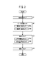
- FIG. 2 is a flow chart showing the procedure of a correction method for correcting the rotation center position of the machine tool 12 in the machine coordinate system.
- the correction method includes a preprocessing step S1, a data acquisition step S2, a calculation step S3 and a correction step S4.
- a preprocessing step S1 a data acquisition step S2, a calculation step S3 and a correction step S4.
- Each of the preprocessing step S1, the data acquisition step S2, the calculation step S3, and the correction step S4 will be described in detail below.
- FIG. 3 is a diagram showing grooves machined in the workpiece 20 in the preprocessing step S1.
- the preprocessing step S ⁇ b>1 is a step of processing a first circular processing groove G ⁇ b>1 and a second circular processing groove G ⁇ b>2 having different diameters and the same center on the processing surface of the workpiece 20 .
- the first circular machined groove G1 is formed under the control of the relative movement control section 26 and the rotation control section 27. That is, the relative movement control section 26 controls the movable member 18 so that the tool 22 moves to the first position P1. Thereafter, while the tool 22 is positioned at the first position P1, the rotation control section 27 rotates the rotating member 16 so as to rotate at a predetermined rotation speed. Thereby, the first circular processed groove G1 is formed.
- the second circular machined groove G2 is formed under the control of the relative movement control section 26 and the rotation control section 27 in the same manner as the first circular machined groove G1. That is, the relative movement control section 26 controls the movable member 18 so that the tool 22 moves to the second position P2. Thereafter, while the tool 22 is positioned at the second position P2, the rotation control section 27 rotates the rotating member 16 so as to rotate at a predetermined rotation speed. Thereby, the second circular processed groove G2 is formed.
- the second position P2 is a position separated by a distance X' from the first position P1 in the first direction (the direction corresponding to the X-axis or the Y-axis).
- the centers of the first circular processed groove G1 and the second circular processed groove G2 coincide with the actual rotation center position CP of the rotating member 16 .
- the first position P1 and the distance X' between the first position P1 and the second position P2 are set in advance by a calculation program.
- the first position P1 and the distance X′ between the first position P1 and the second position P2 may be changed according to the user's operation on the operation unit of the machine tool system 10 .
- the data acquisition step S2 is a step of acquiring shape data regarding the shapes of the first circular processed groove G1 and the second circular processed groove G2.
- the data acquisition unit 30 (FIG. 1) of the arithmetic unit 28 acquires the position coordinates (Mx, My) of the machine coordinate system of the first position P1 and the coordinates between the first position P1 and the second position P2. and the distance X' of are obtained as shape data.
- the data acquisition unit 30 may acquire the position coordinates (Mx, My) and the distance X' from the relative movement control unit 26, or may obtain the position coordinates (Mx, My) and the distance X' by analyzing the calculation program. ' can be obtained.
- FIG. 4 is a diagram showing the state of measurement.
- the data acquisition step S2 includes a first measurement step S2A (Fig. 2).
- the first measurement step S2A is a step of measuring the shapes of the first circular processed groove G1 and the second circular processed groove G2 along the first measurement path D1.
- the data acquisition step S2 also includes a second measurement step S2B (FIG. 2).
- the second measurement step S2B is a step of measuring the shapes of the first circular processed groove G1 and the second circular processed groove G2 along the second measurement path D2.
- the first measurement path D1 and the second measurement path D2 are in a parallel relationship, and the interval H between the first measurement path D1 and the second measurement path D2 is set in advance by a calculation program. Note that the setting of the interval H between the first measurement path D1 and the second measurement path D2 may be changed according to the user's operation on the operation unit of the machine tool system 10 .
- the relative movement control section 26 controls the movable member 18 so that the measuring device 24 passes through the first circular groove G1 and the second circular groove G2 along the first direction. Thereby, the measuring device 24 moves along the first measurement path D1. During this movement, the measuring device 24 measures the first measurement path D1.
- the measured value of the measuring device 24 is obtained as a waveform in which the distance from the workpiece 20 peaks corresponding to the positions of the first circular processed groove G1 and the second circular processed groove G2 that intersect the first measurement path D1. (See Figure 5).
- the relative movement control unit 26 moves the measuring device 24 offset in the second direction orthogonal to the first direction so that it passes through the first circular groove G1 and the second circular groove G2. It controls the movable member 18 along one direction. This causes the measuring device 24 to move along the second measurement path D2. During this movement, the measuring device 24 measures the second measurement path D2.
- the measured value of the measuring device 24 has a peak distance from the workpiece 20 corresponding to the positions of the first circular processed groove G1 and the second circular processed groove G2 that intersect with the second measurement path D2. obtained as a waveform that takes
- the data acquisition unit 30 of the calculation device 28 further acquires shape data. That is, the data acquisition unit 30 obtains the distance H between the first measurement path D1 and the second measurement path D2 and the measurement values of the measurement device 24 measured in the first measurement step S2A and the second measurement step S2B. , is acquired as shape data.
- the data acquisition unit 30 may acquire the distance H between the first measurement path D1 and the second measurement path D2 from the relative movement control unit 26, or may obtain the distance H between the first measurement path D1 and the second measurement path D2 by analyzing the calculation program. A distance H between D1 and the second measurement path D2 may be obtained.
- FIG. 6 is a conceptual diagram showing how the calculation is performed in the calculation step S3.
- the calculation step S3 is a step of calculating the amount of deviation between the rotation center position in the machine coordinate system and the rotation center position CP of the rotating member 16 based on the shape data acquired in the data acquisition step S2.
- the calculation step S3 includes a coordinate calculation step S3A and a deviation amount calculation step S3B.
- the coordinate calculation unit 32 (FIG. 2) of the calculation device 28 calculates the first position P1 based on the actual rotation center position CP (FIG. 3) of the rotary member 16 based on the shape data. Then, the position coordinates ( ⁇ X, ⁇ Y) are calculated.
- the calculation method of the coordinate calculation unit 32 is given as an example. That is, the coordinate calculator 32 calculates the radius R 1 of the first circular processed groove G1 according to formula (1). In addition, the coordinate calculation unit 32 calculates the radius R2 of the second circular processed groove G2 by the formula (2). For this calculation, the measurement value of the measuring device 24 and the interval H between the first measurement path D1 and the second measurement path D2 are used.
- x 1 is the distance from the intersection point P11 between the first measurement path D1 and the first circular machined groove G1 to the virtual line VL passing through the rotation center position CP of the rotating member 16 and perpendicular to the first measurement path D1.
- distance (Fig. 6) is the distance from the intersection point P21 between the second measurement path D2 and the first circular machined groove G1 to the virtual line VL (FIG. 6).
- x 2 is the distance from the intersection point P12 of the first measurement path D1 and the second circular machined groove G2 to the virtual line VL
- X 2 in the equation (2) is the second measurement path D2 and It is the distance from the intersection point P22 with the second circular processed groove G2 to the virtual line VL (FIG. 6).
- the coordinate calculation unit 32 calculates the position coordinates ( ⁇ X, ⁇ Y) corresponding to the first position P1 with reference to the rotation center position CP, using equation (3). For this calculation, the radius R1 of the first circular processed groove G1, the radius R2 of the second circular processed groove G2, and the distance X' (Fig. 3) between the first position P1 and the second position P2 are Used.
- S in equation (3) is a value obtained from Heron's formula in equation (4).
- the deviation amount calculation unit 34 (FIG. 1) of the arithmetic device 28 calculates the difference between the position coordinates ( ⁇ X, ⁇ Y) and the position coordinates (Mx, My) of the first position P1 in the machine coordinate system. is calculated as the deviation amount.
- the position coordinates ( ⁇ X, ⁇ Y) are calculated by the coordinate calculator 32 in the coordinate calculation step S3A.
- the output unit 36 (FIG. 1) of the computing device 28 outputs the calculated deviation amount to the outside. If there is a difference (deviation) in at least one of the X component and the Y component between the calculated position coordinates and the position coordinates of the machine coordinate system, the output unit 36 indicates that the rotation center position of the machine coordinate system is shifted. may be output to the outside together with the amount of deviation.
- the correction step S4 is a step of correcting the rotation center position of the rotating member 16 in the machine coordinate system based on the amount of deviation calculated in the calculation step S3.
- the control device 14 compares the deviation amount calculated by the deviation amount calculation unit 34 of the arithmetic device 28 with a threshold value. When the amount of deviation exceeds the threshold, the control device 14 corrects the rotation center position in the machine coordinate system so that the amount of deviation becomes smaller than the threshold.
- the position coordinates ( ⁇ X, ⁇ Y) are calculated. Further, in the present embodiment, the difference between the position coordinates ( ⁇ X, ⁇ Y) and the first position P1 (position coordinates (Mx, My) in the machine coordinate system) is the rotation center position of the rotating member 16 in the machine coordinate system. , is calculated as the amount of deviation from the actual rotation center position CP of the rotating member 16 .
- control device 14 that controls the machine tool 12 is equipped with an arithmetic device 28 .
- the rotation center position in the machine coordinate system is corrected based on the amount of deviation.
- the rotation center position in the machine coordinate system can be corrected if there is a deviation, and as a result, the machining accuracy can be improved.
- the rotating member 16 is rotated to form the first circular machining groove G1.
- the rotating member 16 is rotated to form the second circular machining groove G2.
- the first circular machined groove G1 and the second circular machined groove G2 can be formed without previously forming the first circular machined groove G1 and the second circular machined groove G2 by a machining device different from the machining system 10 . It is possible to obtain shape data about the shape of
- the measuring device 24 attached to the movable member 18 controls the movable member 18 so as to pass through the first circular processed groove G1 along the first direction, thereby determining the shape of the first circular processed groove G1. is measured.
- the measuring device 24 controls the movable member 18 to pass through the second circular groove G2 along the first direction, and the shape of the second circular groove G2 is measured.
- the measuring device 24 offset in the second direction perpendicular to the first direction controls the movable member 18 so as to pass through the first circular groove G1 along the second direction, thereby measuring the first circular groove G1. is measured.
- the measuring device 24 offset in the second direction controls the movable member 18 to pass through the second circular groove G2 along the second direction, and the shape of the second circular groove G2 is measured.
- the measured values of the shapes of the first circularly machined groove G1 and the second circularly machined groove G2 are acquired as shape data without using another measuring machine different from the machine tool 12 and the measuring device 24. be able to.
- the first circular machined groove G1 and the second circular machined groove G2 may be machined on the machined surface of the workpiece 20 by another machining device different from the machining system 10 .
- the first position P1 (FIG. 3) and the distance X′ (FIG. 3) between the first position P1 and the second position P2 (FIG. 3) are, for example, is input according to the operation of Further, the data acquisition unit 30 of the arithmetic unit 28 acquires the input position coordinates (Mx, My) and the distance X' as shape data.
- the shapes of the first circular groove G1 and the second circular groove G2 may be measured by another measuring machine different from the machine tool 12 and the measuring device 24.
- the data acquisition unit 30 of the arithmetic device 28 obtains the distance H (FIG. 4) between the first measurement path D1 and the second measurement path D2, the first circular groove G1 and the A measured value of the shape of the second circular processed groove G2 is acquired as shape data.
- the data acquisition unit 30 may acquire the distance H (FIG. 4) and the measurement value input according to the user's operation on the operation unit of the machine tool system 10 as the shape data.
- a rotary member (16) on which an object (20) to be processed is arranged and a tool (22) for machining the object to be processed are attached so as to be relatively movable with respect to the rotary member.
- the arithmetic unit calculates a first circular machined groove (G1) machined by the rotation of the rotating member when the tool is at a first position (P1) in the machine coordinate system, and a data acquisition unit (30) for acquiring shape data relating to a shape of a second circular machined groove (G2) machined by rotation of the rotating member when the tool is located at position 2 (P2); a coordinate calculation unit (32) for calculating position coordinates ( ⁇ X, ⁇ Y) corresponding to the first position based on the rotation center position (CP) of the rotating member; and a shift amount calculation unit (34) that calculates the shift amount as the shift amount.
- the computing device may be mounted on a control device (14) that controls the machine tool. As a result, it is possible to determine whether there is a deviation between the rotation center position in the machine coordinate system and the actual rotation center position without connecting the arithmetic device to the control device.
- a second aspect of the invention is a machine tool system (10) comprising the arithmetic device, the machine tool, the control device for controlling the machine tool, the first circular machined groove, and the second circular machined groove.
- the control device may correct the rotation center position in the machine coordinate system based on the deviation amount. As a result, the rotation center position in the machine coordinate system can be corrected, and as a result, machining accuracy can be improved.
- a third aspect of the invention is a machine tool having a rotating member for rotating an object to be processed, and a movable member to which a tool for processing the object to be processed is attached and which is provided so as to be relatively movable with respect to the rotating member.
- This is a correction method for correcting the rotation center position in the machine coordinate system.
- a correction method includes a first circular machined groove machined by rotation of the rotating member when the tool is at a first position in the machine coordinate system, and the tool is at a second position different from the first position.
- the correction method includes controlling the movable member so that the tool moves to the first position, then rotating the rotating member to form the first circular machining groove, and moving the tool to the second position.
- a pretreatment step (S1) may be included in which the rotating member is rotated to form the second circular processing groove after controlling the movable member as above.
- the data acquisition step measures the shape by controlling the movable member such that a measuring device attached to the movable member passes through the first circular processed groove and the second circular processed groove along a first direction.
- a first measuring step S2A
- the measuring device offset in a second direction perpendicular to the first direction forms the first circular processed groove and the second circular processed groove along the first direction.
- a second measuring step S2B of controlling the movable member so as to pass through and measuring the shape, and in the coordinate calculating step, the measured values measured in the first measuring step and the second measuring step may be used as the shape data.
- the first circularly machined groove and the second circularly machined groove can be measured without measuring the shapes of the first circularly machined groove and the second circularly machined groove using a measuring machine different from the machine tool and the measuring device. can be acquired as shape data.
Landscapes
- Engineering & Computer Science (AREA)
- Human Computer Interaction (AREA)
- Manufacturing & Machinery (AREA)
- Physics & Mathematics (AREA)
- General Physics & Mathematics (AREA)
- Automation & Control Theory (AREA)
- Mechanical Engineering (AREA)
- Automatic Control Of Machine Tools (AREA)
- Numerical Control (AREA)
Priority Applications (4)
| Application Number | Priority Date | Filing Date | Title |
|---|---|---|---|
| DE112022000605.6T DE112022000605T5 (de) | 2021-03-23 | 2022-03-17 | Rechenvorrichtung, Bearbeitungssystem und Korrekturverfahren |
| US18/549,600 US20250028296A1 (en) | 2021-03-23 | 2022-03-17 | Computation device, machining system, and correction method |
| CN202280021848.5A CN117043693A (zh) | 2021-03-23 | 2022-03-17 | 运算装置、工作系统及校正方法 |
| JP2023509094A JPWO2022202591A1 (https=) | 2021-03-23 | 2022-03-17 |
Applications Claiming Priority (2)
| Application Number | Priority Date | Filing Date | Title |
|---|---|---|---|
| JP2021048697 | 2021-03-23 | ||
| JP2021-048697 | 2021-03-23 |
Publications (1)
| Publication Number | Publication Date |
|---|---|
| WO2022202591A1 true WO2022202591A1 (ja) | 2022-09-29 |
Family
ID=83397257
Family Applications (1)
| Application Number | Title | Priority Date | Filing Date |
|---|---|---|---|
| PCT/JP2022/012174 Ceased WO2022202591A1 (ja) | 2021-03-23 | 2022-03-17 | 演算装置、工作システムおよび補正方法 |
Country Status (5)
| Country | Link |
|---|---|
| US (1) | US20250028296A1 (https=) |
| JP (1) | JPWO2022202591A1 (https=) |
| CN (1) | CN117043693A (https=) |
| DE (1) | DE112022000605T5 (https=) |
| WO (1) | WO2022202591A1 (https=) |
Citations (4)
| Publication number | Priority date | Publication date | Assignee | Title |
|---|---|---|---|---|
| JPS61265243A (ja) * | 1985-05-17 | 1986-11-25 | Hitachi Ltd | バイト位置決め装置 |
| JPH02156308A (ja) * | 1988-12-08 | 1990-06-15 | Fanuc Ltd | 数値制御装置 |
| JPH02180545A (ja) * | 1988-12-28 | 1990-07-13 | Toshiba Mach Co Ltd | 工具の自動芯合せ方法とその装置 |
| JP2006313540A (ja) * | 2005-05-06 | 2006-11-16 | Satisloh Gmbh | 特に眼科レンズの製造に使用するバイト旋回機器内においてツール(複数の場合もある)の自動キャリブレーションを行う方法 |
Family Cites Families (14)
| Publication number | Priority date | Publication date | Assignee | Title |
|---|---|---|---|---|
| GB8622218D0 (en) * | 1986-09-16 | 1986-10-22 | Renishaw Plc | Calibration for automatic machine tool |
| JPH05200649A (ja) | 1992-01-27 | 1993-08-10 | Toyoda Mach Works Ltd | 工具心出し装置 |
| US6437823B1 (en) * | 1999-04-30 | 2002-08-20 | Microsoft Corporation | Method and system for calibrating digital cameras |
| US6934601B2 (en) * | 1999-09-20 | 2005-08-23 | Hitachi, Ltd. | Numerically controlled curved surface machining unit |
| US6865498B2 (en) * | 2001-11-30 | 2005-03-08 | Thermwood Corporation | System for calibrating the axes on a computer numeric controlled machining system and method thereof |
| GB0525306D0 (en) * | 2005-12-13 | 2006-01-18 | Renishaw Plc | Method of machine tool calibration |
| JP4902316B2 (ja) * | 2006-11-10 | 2012-03-21 | 東芝機械株式会社 | 斜め加工のための5軸加工機の姿勢保証システム |
| TWI329246B (en) * | 2007-03-23 | 2010-08-21 | Univ Chung Yuan Christian | Measuring method and system for cnc machine |
| WO2009057229A1 (ja) * | 2007-11-02 | 2009-05-07 | Makino Milling Machine Co., Ltd. | エラーマップ作成方法及び装置並びにエラーマップ作成機能を有した数値制御工作機械 |
| US8515579B2 (en) * | 2009-12-09 | 2013-08-20 | GM Global Technology Operations LLC | Systems and methods associated with handling an object with a gripper |
| EP2492635B1 (de) * | 2011-02-22 | 2013-05-29 | Siemens Aktiengesellschaft | Kalibrierverfahren für einen kugelförmigen Messtaster |
| US9784554B2 (en) * | 2012-03-20 | 2017-10-10 | Hurco Companies, Inc. | Method for measuring a rotary axis of a machine tool system |
| US10203682B2 (en) * | 2016-06-14 | 2019-02-12 | Doosan Machine Tools Co., Ltd. | Position controller for controlling a rotation center of a tilting head |
| CN109358568B (zh) * | 2018-12-17 | 2020-04-07 | 大连理工大学 | 基于矢量场的曲面分区加工轨迹拓扑形状设计方法 |
-
2022
- 2022-03-17 JP JP2023509094A patent/JPWO2022202591A1/ja not_active Withdrawn
- 2022-03-17 CN CN202280021848.5A patent/CN117043693A/zh not_active Withdrawn
- 2022-03-17 DE DE112022000605.6T patent/DE112022000605T5/de not_active Withdrawn
- 2022-03-17 US US18/549,600 patent/US20250028296A1/en active Pending
- 2022-03-17 WO PCT/JP2022/012174 patent/WO2022202591A1/ja not_active Ceased
Patent Citations (4)
| Publication number | Priority date | Publication date | Assignee | Title |
|---|---|---|---|---|
| JPS61265243A (ja) * | 1985-05-17 | 1986-11-25 | Hitachi Ltd | バイト位置決め装置 |
| JPH02156308A (ja) * | 1988-12-08 | 1990-06-15 | Fanuc Ltd | 数値制御装置 |
| JPH02180545A (ja) * | 1988-12-28 | 1990-07-13 | Toshiba Mach Co Ltd | 工具の自動芯合せ方法とその装置 |
| JP2006313540A (ja) * | 2005-05-06 | 2006-11-16 | Satisloh Gmbh | 特に眼科レンズの製造に使用するバイト旋回機器内においてツール(複数の場合もある)の自動キャリブレーションを行う方法 |
Also Published As
| Publication number | Publication date |
|---|---|
| DE112022000605T5 (de) | 2023-11-23 |
| JPWO2022202591A1 (https=) | 2022-09-29 |
| CN117043693A (zh) | 2023-11-10 |
| US20250028296A1 (en) | 2025-01-23 |
Similar Documents
| Publication | Publication Date | Title |
|---|---|---|
| JP6295070B2 (ja) | 多軸工作機械の幾何誤差同定方法及び多軸工作機械 | |
| KR101130596B1 (ko) | 기상 계측 장치의 프로브 장착 위치 산출 방법 | |
| JP4959028B1 (ja) | 誤差測定装置及び誤差測定方法 | |
| CN105881102B (zh) | 使用了拍摄部的工件的定位装置 | |
| EP3327524B1 (en) | Kinematic calibration | |
| JP6942577B2 (ja) | 工作機械の数値制御装置及び数値制御方法 | |
| US8494800B2 (en) | Method and program for identifying mechanical errors | |
| US9506736B2 (en) | Measurement system | |
| CN112008496B (zh) | 机床对象物的位置计测方法及位置计测系统 | |
| JP3527565B2 (ja) | 歯車計測方法及びnc歯車加工機 | |
| EP1579168A1 (en) | Workpiece inspection method | |
| CN105723182A (zh) | 减小在确定工件坐标或加工工件时所采用的旋转设备的误差 | |
| CN114253217B (zh) | 带有自修正功能的五轴机床rtcp自动标定方法 | |
| JP7266511B2 (ja) | 工作機械における対象物の位置計測方法及び位置計測システム、位置計測プログラム | |
| KR20220023271A (ko) | 5축 공작기계의 기하학적 오차 측정 방법 | |
| CN109773589A (zh) | 对工件表面进行在线测量和加工导引的方法及装置、设备 | |
| KR20220023270A (ko) | 수직형 5축 공작기계의 기하학적 오차 측정 방법 | |
| JP5201871B2 (ja) | 形状測定方法及び装置 | |
| JP7396857B2 (ja) | 表示装置 | |
| CN110487233B (zh) | 校正机器人用户坐标系的方法及系统 | |
| WO2022202591A1 (ja) | 演算装置、工作システムおよび補正方法 | |
| CN114589545B (zh) | 一种复杂曲面变形在线检测及五轴补偿加工方法 | |
| JP3025413B2 (ja) | 輪郭形状測定方法及びその装置 | |
| JP5437693B2 (ja) | 主軸又はアタッチメント主軸の補正値自動計測方法 | |
| TW202338533A (zh) | 被加工物之加工方法及被加工物之加工系統 |
Legal Events
| Date | Code | Title | Description |
|---|---|---|---|
| 121 | Ep: the epo has been informed by wipo that ep was designated in this application |
Ref document number: 22775379 Country of ref document: EP Kind code of ref document: A1 |
|
| ENP | Entry into the national phase |
Ref document number: 2023509094 Country of ref document: JP Kind code of ref document: A |
|
| WWE | Wipo information: entry into national phase |
Ref document number: 18549600 Country of ref document: US Ref document number: 112022000605 Country of ref document: DE |
|
| WWE | Wipo information: entry into national phase |
Ref document number: 202280021848.5 Country of ref document: CN |
|
| 122 | Ep: pct application non-entry in european phase |
Ref document number: 22775379 Country of ref document: EP Kind code of ref document: A1 |