WO2022202418A1 - アンテナ及びアンテナ装置 - Google Patents
アンテナ及びアンテナ装置 Download PDFInfo
- Publication number
- WO2022202418A1 WO2022202418A1 PCT/JP2022/011082 JP2022011082W WO2022202418A1 WO 2022202418 A1 WO2022202418 A1 WO 2022202418A1 JP 2022011082 W JP2022011082 W JP 2022011082W WO 2022202418 A1 WO2022202418 A1 WO 2022202418A1
- Authority
- WO
- WIPO (PCT)
- Prior art keywords
- conductor
- antenna
- ground
- legs
- ground plane
- Prior art date
- Legal status (The legal status is an assumption and is not a legal conclusion. Google has not performed a legal analysis and makes no representation as to the accuracy of the status listed.)
- Ceased
Links
Images






Classifications
-
- H—ELECTRICITY
- H01—ELECTRIC ELEMENTS
- H01Q—ANTENNAS, i.e. RADIO AERIALS
- H01Q13/00—Waveguide horns or mouths; Slot antennas; Leaky-waveguide antennas; Equivalent structures causing radiation along the transmission path of a guided wave
- H01Q13/08—Radiating ends of two-conductor microwave transmission lines, e.g. of coaxial lines, of microstrip lines
-
- H—ELECTRICITY
- H01—ELECTRIC ELEMENTS
- H01Q—ANTENNAS, i.e. RADIO AERIALS
- H01Q15/00—Devices for reflection, refraction, diffraction or polarisation of waves radiated from an antenna, e.g. quasi-optical devices
- H01Q15/14—Reflecting surfaces; Equivalent structures
-
- H—ELECTRICITY
- H01—ELECTRIC ELEMENTS
- H01Q—ANTENNAS, i.e. RADIO AERIALS
- H01Q5/00—Arrangements for simultaneous operation of antennas on two or more different wavebands, e.g. dual-band or multi-band arrangements
- H01Q5/30—Arrangements for providing operation on different wavebands
- H01Q5/378—Combination of fed elements with parasitic elements
Definitions
- the present invention relates to antennas and antenna devices.
- Patent Document 1 discloses an antenna device having a metal plate portion and leg portions extending from the metal plate portion toward the front surface of the circuit board and fixed to the circuit board.
- the resonance frequency of the antenna device can be lowered by adding a capacitor to increase the capacitance between elements.
- the addition of the capacitor complicates the configuration of the antenna device.
- An example of the object of the present invention is to realize an antenna with a low resonance frequency with a simple configuration.
- Other objects of the present invention will become clear from the description herein.
- a ground portion a conductor positioned to face the ground portion, a support portion that supports the conductor so as to be physically separated from the ground portion by a predetermined distance
- An antenna comprising
- an antenna with a low resonance frequency can be realized with a simple configuration.
- FIG. 2 is a perspective view of a first antenna 20;
- FIG. 3 is an exploded perspective view of the first antenna 20;
- FIG. 3 is a perspective view of the main body 31 of the conductor 30 as viewed from the back surface 31C side.
- FIG. 3 is a developed view of a conductor 30;
- FIG. 3 is a perspective view and a side view of conductors 30A to 30C.
- 4 is a graph showing an example of frequency characteristics of each of conductors 30A to 30C;
- 3A and 3B are a perspective view and a side view of a conductor 30D and a conductor 30E;
- FIG. 4 is a graph showing an example of frequency characteristics of each of a conductor 30D and a conductor 30E;
- 9A is a diagram relating to the virtual volume of the conductor 30, and
- FIG. 9A is a diagram for explaining the virtual volume of the conductor 30.
- FIG. FIG. 9B is a graph showing an example of frequency characteristics when the virtual volume of the conductor 30 is changed.
- 10A is a perspective view of a modified conductor 30F having extensions 33 extending in a direction toward a central portion 31D.
- FIG. FIG. 10B is a perspective view of a modified conductor 30G having extensions 33 extending in a direction toward central portion 31D.
- 11A is a view showing a modification of the supporting structure of the conductor 30, and FIG.
- FIG. 11A is a view of the first antenna 20 having the insulator 50 between the ground plane 10 and the extension 33.
- FIG. 11B is a diagram of first antenna 20 having support portion 40 that supports both body portion 31 and extension portion 33.
- FIG. 12A is a view showing a modification of the support structure of the conductor 30, and
- FIG. 12A is a view of the first antenna 20 having a cross-shaped support portion 40.
- FIG. FIG. 12B is a diagram of first antenna 20 having multiple supports 40 .
- FIG. 4 is a diagram of the first antenna 20 in which the cover part 6 supports the conductor 30;
- 14A is a plan view of conductor 30 with slot 37.
- FIG. FIG. 14B is a plan view of conductor 30 with slot 37 having a meander.
- FIG. 1 is a perspective view of an antenna device 100;
- FIG. 2 is an exploded perspective view of the antenna device 100;
- FIG. 4 is a graph showing an example of return loss in the antenna device 100;
- 4 is a graph showing an example of gain in the zenith direction in the antenna device 100;
- FIG. 3 is an explanatory diagram of a feeding method in the antenna device 100;
- FIG. 19A is a block diagram of an antenna device 100 that feeds both the first antenna 20 and the second antenna 70.
- FIG. FIG. 19B is a block diagram of the antenna device 100 feeding only the second antenna 70.
- FIG. 4 is a graph showing an example of gain in the zenith direction in the antenna device 100;
- FIG. 4 is a graph showing an example of gain in the zenith direction in the antenna device 100;
- FIG. 4 is a graph showing an example of gain in the zenith direction in the antenna device 100;
- FIG. 4 is a graph showing an example of gain in the zeni
- FIG. 20A is a graph showing an example of the gain in the zenith direction in the antenna device 100 that feeds both the first antenna 20 and the second antenna 70.
- FIG. 20B is a graph showing an example of the gain in the zenith direction in the antenna device 100 feeding only the second antenna 70 .
- FIG. 1 is a perspective view of the first antenna 20.
- FIG. FIG. 2 is an exploded perspective view of the first antenna 20.
- the direction along the line connecting the central portion 31D of the conductor 30 of the first antenna 20 and one of the two feeding points 36A is defined as the X direction.
- the direction along the line connecting the other feeding point 36A and the central portion 31D is defined as the Y direction.
- a vertical direction perpendicular to the X direction and the Y direction is defined as the Z direction.
- the directions shown in FIGS. 1 and 2 are the +X direction and the +Y direction, and the zenith direction (upward direction) is the +Z direction. Details of the central portion 31D will be described later.
- the direction along the line segment connecting the central portion 31D and the feeding point 36A is defined as the X direction
- a direction perpendicular to the X direction is defined as a Y direction.
- the first antenna 20 is provided, for example, in an in-vehicle antenna device mounted in a vehicle (not shown).
- An in-vehicle antenna device is housed, for example, in a cavity between a roof panel of a vehicle and a roof lining on the ceiling surface of the vehicle interior.
- the first antenna 20 may be provided in the housing of a general shark fin antenna.
- the first antenna 20 may be provided in an antenna device attached to the instrument panel.
- the first antenna 20 is, for example, a planar antenna used in the GNSS (Global Navigation Satellite System) system.
- the first antenna 20 receives, for example, 1.5 GHz band radio waves from an artificial satellite.
- the first antenna 20 may receive radio waves in a plurality of frequency bands such as 1.2 GHz band and 1.6 GHz band.
- the communication standard and frequency band that can be received by the first antenna 20 are not limited to those described above, and other communication standards and frequency bands may be used.
- the first antenna 20 may be used in a satellite digital audio radio service (SDARS) system to receive left-hand circularly polarized waves (satellite signals) in the 2.3 GHz band.
- SDARS satellite digital audio radio service
- the first antenna 20 has a ground plane 10 , a conductor 30 and a support portion 40 .
- the ground plane 10 is an element used as the ground of the first antenna 20 .
- the base plate 10 is a substantially rectangular metal plate.
- substantially quadrilateral refers to a shape consisting of four sides, including squares and rectangles. good.
- a notch (concave portion) or protrusion (convex portion) may be provided on a part of the sides.
- the base plate 10 may be, for example, a circular or elliptical plate-like member.
- the base plate 10 may have a shape other than a plate shape as long as it is a metal member that functions as a ground.
- the base plate 10 is installed on the base 1 made of metal, for example.
- the first antenna 20 may not have the ground plane 10 and the conductor 30 and the support portion 40 may be directly installed on the base 1 .
- the base 1 may be used as a ground.
- an element used as a ground, including the ground plane 10 may be referred to as a "ground portion".
- one object of the present embodiment is to bring the conductor 30 closer to the ground while preventing the conductor 30 from coming into contact with the ground. Therefore, by disposing a plate-like member such as the ground plane 10 under the conductor 30, the distance between the conductor 30 and the ground portion can be easily designed.
- the conductor 30 is an element capable of receiving signals (radio waves) in a desired frequency band. Also, the conductor 30 is a conductive element electrically coupled to the ground plane 10 (ground portion). In this embodiment, the conductor 30 is an element capacitively coupled with the ground plane 10 . However, the conductor 30 is not limited to being capacitively coupled with the ground plane 10, and may be an element for other electrical coupling such as electrostatic coupling, electromagnetic resonance coupling, or electric field coupling.
- the conductor 30 is positioned so as to face the ground plane 10 . Also, the conductor 30 is physically separated from the ground plane 10 by a predetermined distance.
- two elements for example, element A and element B
- that are "physically separated by a predetermined distance" means that there is a gap between element A and element B. Specifically, it means that there is a predetermined gap between the end of the element A closest to the element B side and the end of the element B closest to the element A side.
- a Z-direction have a predetermined amount of gap between them.
- another member may be provided in the gap between the conductor 30 and the ground plane 10 .
- the conductor 30 Since the conductor 30 is physically separated from the ground plane 10 by a predetermined distance, the conductor 30 floats in the +Z direction with respect to the ground plane 10 . That is, the conductor 30 is not in physical contact with the ground plane 10 . In other words, the conductor 30 and the ground plane 10 are physically out of contact.
- the size of the conductor 30 and the size of the ground plane 10 are substantially the same when viewed from the +Z direction on the XY plane.
- the size of the conductor 30 and the size of the ground plane 10 may be different.
- the size of the ground plane 10 may be larger than the size of the conductor 30 .
- FIG. 3 is a perspective view of the body portion 31 of the conductor 30 viewed from the back surface 31C side.
- FIG. 4 is an exploded view of the conductor 30.
- the conductor 30 has a body portion 31 and leg portions 32 .
- the body portion 31 is a portion of the conductor 30 that is positioned so as to face the ground plane 10 .
- the body portion 31 is substantially quadrilateral.
- the main body portion 31 may be circular or elliptical, or polygonal other than a substantially quadrilateral.
- the main body portion 31 and the leg portion 32 may have any shape as long as the conductor 30 can receive signals (radio waves) in a desired frequency band.
- a feeding point 36A is provided on the main body 31.
- a feeding point 36A is a point where the feeding line 36 is electrically connected to the main body portion 31 .
- two feeding points 36A are provided.
- One feeding point 36A is provided at a position shifted in the +X direction from the central portion 31D of the main body portion 31 .
- the other feeding point 36A is provided at a position displaced from the central portion 31D of the main body portion 31 in the -Y direction.
- the position of the feeding point 36A is not limited to this.
- the “center portion 31D of the body portion 31” refers to the center point of the outer edge shape of the body portion 31, that is, the geometric center.
- the main body 31 has, for example, a substantially square shape with equal vertical and horizontal lengths so that desired circularly polarized waves can be transmitted and received.
- the “substantially square” is a shape included in the above-described “substantially quadrilateral”.
- a configuration in which only one power supply line 36 is connected to the main body 31, that is, a single power supply system may be adopted.
- the main body 31 of the single feeding system has, for example, a substantially rectangular shape with different lengths and widths so that desired circularly polarized waves can be transmitted and received.
- the “substantially rectangular” is a shape included in the above-described “substantially quadrilateral”.
- the “central portion 31D of the body portion 31” is the point where the diagonal lines of the body portion 31 intersect.
- a power feeding system other than the two power feeding system or the one power feeding system may be adopted, for example, a four power feeding system (four-point power feeding) may be adopted.
- the leg portion 32 is a portion extending from the main body portion 31 . As shown in FIG. 3, four legs 32A-32D extend from body portion 31. As shown in FIG. However, the number of legs 32 of the conductor 30 is not limited to four, and may be any number other than four. For example, two legs 32 may extend from body 31 . When the conductor 30 has two legs 32, only the legs 32A and 32C, or only the legs 32B and 32D, each leg 32 is paired with the main body 31. It is provided at a corner position. This facilitates the design of the layout of the feed point 36A. However, the positions where the two legs 32 are provided are not limited to this. Furthermore, the conductor 30 may have one leg portion 32 , or the conductor 30 may have no leg portion 32 .
- the four legs 32A to 32D are positioned rotationally symmetrical to the outer edge 31A of the main body 31.
- the four legs 32A to 32D are "positioned so as to be rotationally symmetrical" means that when the conductor 30 is rotated by a predetermined angle around the central portion 31D in a plan view of the XY plane viewed from the +Z direction, It means that the positions of the legs 32 are matched.
- the predetermined angle is an angle obtained by dividing 360° by the number of legs 32 that the conductor 30 has.
- the conductor 30 has four legs 32A to 32D, the positions of the legs 32 are aligned when the conductor 30 is rotated 90° (360°/4) around the center 31D. . Positioning the four legs 32A to 32D so as to be rotationally symmetrical is particularly advantageous in that the loss of radio waves can be suppressed in the case of the conductor 30 that receives circularly polarized radio waves.
- “rotationally symmetrical positions” is not limited to the case where the positions of the leg portions 32 are completely matched when the conductor 30 is rotated around the central portion 31D by a predetermined angle, and is not limited to a predetermined range. This includes cases where the deviation is within the range. This is because the position and size of the legs 32 change due to various factors such as tolerance.
- the "deviation" within a predetermined range may be a degree that can suppress the loss of radio waves for the conductor 30 that receives circularly polarized radio waves.
- the angle at which the leg portions 32 actually match may deviate from the predetermined angle within a range of about ⁇ 30%.
- the four legs 32A to 32D do not have to be positioned rotationally symmetrically with respect to the outer edge 31A of the main body 31. As shown in FIG.
- the conductor 30 has one leg 32. It is good as
- the leg portion 32 extends from the main body portion 31 is limited to the case where the main body portion 31 and the leg portion 32 configured to extend from the main body portion 31 are made of the same metal plate. can't A case in which the body portion 31 and the leg portion 32 are separate bodies and the leg portion 32 is connected (joined) to the body portion 31 so as to extend from the body portion 31 is also included. Further, the body portion 31 and the leg portion 32 may be made of the same metal member, or may be made of different metal members.
- each of the leg portions 32A to 32D the parts constituting the leg portion 32 are indicated with suffixes "A" to "D".
- the extending portion 33 of the leg portion 32A is referred to as "extending portion 33A”.
- the suffix may not be added.
- all four legs 32A to 32D may be simply referred to as “legs 32”.
- all of the extensions 33A to 32D may be simply referred to as "extensions 33”.
- bent portions 35 are provided at the connecting portions between the body portion 31 and the leg portions 32.
- the legs 32 are provided by bending from the main body 31 .
- the leg portion 32 extends toward the front surface of the base plate 10 (ground portion). Therefore, in this embodiment, the leg portion 32 is positioned between the base plate 10 and the main body portion 31 .
- the bent portion 35 is provided on the outer edge portion 31A of the body portion 31 . That is, the leg portion 32 is provided on the outer edge portion 31A of the body portion 31 .
- the bent portion 35 may be provided inside the outer edge portion 31A of the body portion 31 (on the center portion 31D side). That is, the leg portion 32 may be provided on a portion other than the outer edge portion 31A of the main body portion 31 .
- the leg portion 32 has an extension portion 33 as shown in FIGS.
- the extending portion 33 is a member having a facing surface 34 facing the base plate 10 (ground portion) at the leg portion 32 .
- the extending portion 33 is provided so as to be bent from the end portion of the leg portion 32 on the side of the main plate 10 by a bending portion 38 (38A to 38D) further provided at the end portion of the leg portion 32 on the side of the main plate 10. .
- the extending portion 33 may be separate from the leg portion 32 and may be connected (joined) so as to extend from the end portion of the leg portion 32 on the side of the base plate 10 .
- the extending portion 33 and the leg portion 32 are separate members, they may be connected (joined) so as to extend from a portion other than the end portion of the leg portion 32 on the side of the main plate 10 . Also, the leg portion 32 may not have the extending portion 33 . Furthermore, among the plurality of legs 32, those having the bent portion 38 and those having no bent portion 38 may be mixed.
- the extending portion 33 is positioned inside the outer edge portion 31A of the main body portion 31 . That is, the extending portion 33 extends from the outer edge portion 31A toward the central portion 31D. However, the extending portion 33 may be positioned outside the outer edge portion 31A of the body portion 31 . That is, the extending portion 33 may extend outside the outer edge portion 31A of the body portion 31, that is, in a direction away from the central portion 31D.
- the extending portion 33 extends substantially parallel to the front surface of the base plate 10 so as to have a facing surface 34 facing the base plate 10 (ground portion). However, as long as the extending portion 33 has the facing surface 34 , the extending portion 33 does not have to extend substantially parallel to the front surface of the base plate 10 .
- the conductor 30 is made of sheet metal. Specifically, as shown in FIG. 4, the body portion 31 and the leg portions 32A to 32D are integrated. Further, the conductor 30 is bent by having the bent portion 35 and the bent portion 38 to provide the leg portion 32 and the extension portion 33 described above. Therefore, the conductor 30 has a three-dimensional shape.
- leg 32 described above have been described as being common to the four legs 32A to 32D, as shown in FIGS. However, the features of the legs 32 described above may apply to at least one leg 32 out of the four legs 32A-32D. For example, only the leg portions 32A and 32C may be provided with the extending portions 33, and the leg portions 32B and 32D may not be provided with the extending portions 33. Therefore, in the four legs 32A to 32D, the features of the legs 32 described above can be freely combined.
- the support part 40 is a member that supports the conductor 30 so as to physically separate it from the ground plane 10 by a predetermined distance so that a desired capacitance is formed between the conductor 30 and the ground plane 10 (ground part). is.
- the support portion 40 has a cylindrical shape.
- the shape of the support portion 40 is not limited to this, and may be any shape other than a columnar shape as long as it can support the conductor 30, and may be, for example, a rectangular parallelepiped shape.
- the support portion 40 is made of a dielectric such as resin, for example.
- the supporting portion 40 may be formed of a material other than the dielectric as long as the material does not have conductivity.
- the support portion 40 is positioned between the ground plate 10 (ground portion) and the main body portion 31 of the conductor 30 .
- the support part 40 is a member that physically separates the conductor 30 and the ground plane 10 so that a desired capacitance is formed between them. Therefore, if the support portion 40 can support the conductor 30 so as to physically separate it from the ground plane 10 by a predetermined distance, the support portion 40 can be positioned between the ground plane 10 (ground portion) and the body portion 31 of the conductor 30 .
- the cover portion 6 may support the conductor 30 as shown in FIG. 13, which will be described later.
- the support portion 40 is smaller than the main body portion 31 in a plan view of the XY plane seen from the +Z direction. Further, the support portion 40 is positioned substantially in the center of the body portion 31 (conductor 30). Since the potential difference between the substantially center of the body portion 31 and the ground plane 10 (ground portion) is constant at 0, the position of the support portion 40 substantially at the center of the body portion 31 reduces the loss of radio waves and shortens the wavelength. The impact can be suppressed. Desirably, if the size of the support portion 40 in plan view on the XY plane seen from the +Z direction is within 50% of the size of the main body portion 31, the effects of radio wave loss and wavelength shortening can be further suppressed. can be done.
- the size of the support portion 40 may be larger than the size of the main body portion 31 in a plan view of the XY plane viewed from the +Z direction. Also, the support portion 40 does not have to be positioned substantially in the center of the body portion 31 . For example, the support portion 40 may be positioned at the outer edge portion 31A of the main body portion 31 in a plan view of the XY plane viewed from the +Z direction.
- the conductor 30 and the ground plane 10 can be brought closer to each other, and the capacitance between the conductor 30 and the ground plane 10 can be increased.
- the capacitance can be increased by providing a ceramic dielectric between the conductor 30 and the ground plane 10, but the use of ceramic increases the manufacturing cost. Therefore, the configuration having the support portion 40 as in the present embodiment can increase the capacitance between the conductor 30 and the ground plane 10 with a simple configuration. Therefore, an antenna with a low resonance frequency can be realized with a simple configuration.
- the portion of the leg portion 32 close to the base plate 10 is electrically coupled to the base plate 10 .
- the portion of the leg 32 close to the ground plane 10 is capacitively coupled with the ground plane 10 .
- the portion of the leg portion 32 close to the base plate 10 is the extending portion 33 of the leg portion 32 .
- the portion of the leg portion 32 close to the base plate 10 is the end portion of the leg portion 32 on the side of the base plate 10 (ground portion). Thereby, the capacitance between the conductor 30 and the ground plane 10 can be increased.
- the conductor 30 has a plurality of (here, four) legs 32A to 32D, and each of the legs 32A to 32D It has an extension 33 with a facing surface 34 .
- the portion of the leg portion 32 close to the ground plane 10 can be increased, and the capacitance between the conductor 30 and the ground plane 10 can be increased.
- a portion of the leg portion 32 close to the ground plane 10 is provided by bending a sheet metal.
- the presence or absence of a portion of the leg 32 close to the ground plane 10 using different models of the conductor 30 shown in FIGS. do.
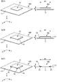
- FIG. 5A is a perspective view and a side view of the conductor 30A
- FIG. 5B is a perspective view and a side view of the conductor 30B
- FIG. 5C is a perspective view and a side view of the conductor 30C.
- a perspective view is shown on the left side and a side view is shown on the right side.
- the illustration of the supporting portion 40, the feeding point 36A, and the feeding line 36 is omitted. .
- the conductor 30A is not provided with the legs 32, and is composed only of the main body 31.
- the conductor 30B has leg portions 32 on both sides of the body portion 31 where the extension portions 33 are not provided.
- the conductor 30C has leg portions 32 on both sides of the body portion 31 on which the extension portions 33 are provided.
- Each of the conductors 30A to 30C has a width W1 in common. Further, each of the conductors 30A to 30C is physically separated from the ground plane 10 so that the upper surface of the body portion 31 is positioned at the height H.
- the distance between the end of the leg portion 32 on the side of the base plate 10 and the base plate 10 in FIG. 5B is equivalent to the distance between the extending portion 33 and the base plate 10 in FIG. 5C. Also, the conductors 30A to 30C and the ground plane 10 are not in physical contact.
- the height H between the main body portion 31 and the ground plane 10 indicates a predetermined distance by which the conductor 30 is physically separated from the ground plane 10 .
- the height H is the same as the ground plane 10 of the legs 32 when the conductor 30 is supported by the support 40.
- the height at which the side edge does not physically contact the base plate 10 is shown.
- FIG. 6 is a graph showing an example of frequency characteristics of each of the conductors 30A to 30C.
- the horizontal axis represents frequency
- the vertical axis represents voltage standing wave ratio (VSWR).
- VSWR voltage standing wave ratio
- the value of the frequency with the lowest voltage standing wave ratio is 3619 MHz for the conductor 30A, 2755 MHz for the conductor 30B, and 2755 MHz for the conductor 30C. , 2133 MHz.
- Comparing the conductor 30A and the conductor 30B based on the results of FIG. part is provided. It can be seen that this increases the capacitance between the conductor 30 and the ground plane 10 and shifts the resonance frequency of the first antenna 20 to the low frequency side. Further, when the conductor 30B and the conductor 30C are compared, the area of the portion of the leg 32 close to the ground plane 10 is increased by having the extension 33 having the facing surface 34 facing the ground plane 10. growing. As a result, the capacitance between the conductor 30 and the ground plane 10 is further increased, and the resonance frequency of the first antenna 20 is further shifted to the low frequency side.
- the verification is omitted here, if the portion of the leg portion 32 that is close to the ground plane 10 is brought closer to the ground plane 10 side, the capacitance between the conductor 30 and the ground plane 10 is further increased, and the first antenna 20 The resonance frequency of is further shifted to the low frequency side.
- the resonance frequency of the first antenna 20 can be adjusted by adjusting the length and width of the extension portion 33. can be adjusted. That is, the resonance frequency of the first antenna 20 can be adjusted to a desired frequency by adjusting the size of the extending portion 33 shown in FIG. 5C in the X direction and the Y direction. Therefore, for example, even if the resonance frequency of the first antenna 20 deviates from the desired frequency due to a change in the size of the substrate (not shown) of the first antenna 20 or the influence of the structure, the desired frequency can be easily obtained. can be adjusted to
- the frequency characteristics of the first antenna 20 were verified using a model in which the leg portion 32 and the extension portion 33 are added to the body portion 31 having a certain length (here, W1). However, the inductance of the conductor 30 is increased by the length of the leg 32 and extension 33 . In the following, the frequency characteristics of the first antenna 20 will be verified using a model in which the influence of the increase in the inductance of the conductor 30 is removed.
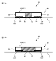
- FIG. 7A is a perspective view and a side view of the conductor 30D
- FIG. 7B is a perspective view and a side view of the conductor 30E.
- a perspective view is shown on the left side
- a side view is shown on the right side.
- the illustration of the supporting portion 40, the feeding point 36A, and the feeding line 36 is omitted. .
- the conductor 30D is not provided with the legs 32, and is composed only of the main body 31.
- the conductor 30E has leg portions 32 on both sides of the body portion 31 on which the extension portions 33 are provided.
- the width of the conductor 30D is the width W2
- the conductor 30E is provided with the leg portion 32 and the extension portion 33 by bending the conductor having the width W2. Therefore, a model is used in which the inductance of the conductor 30D and the inductance of the conductor 30E are substantially the same.
- each of the conductors 30D and 30E is physically separated from the ground plane 10 so that the upper surface of the body portion 31 is positioned at the height H. Also, the extending portion 33 and the base plate 10 in FIG. 7B are physically separated. The conductors 30D-30E and the ground plane 10 are not in physical contact.
- FIG. 8 is a graph showing an example of frequency characteristics of each of the conductors 30D and 30E.
- the horizontal axis represents frequency
- the vertical axis represents voltage standing wave ratio (VSWR).
- VSWR voltage standing wave ratio
- the value of the frequency with the lowest voltage standing wave ratio is 2584 MHz for the conductor 30D and 2133 MHz for the conductor 30E.
- the frequency band tends to widen as the conductor 30 becomes thicker in the Z direction.
- the virtual volume of the conductor 30 is defined, and changes in the frequency band due to changes in the virtual volume are verified.
- FIG. 9A is a diagram explaining the virtual volume of the conductor 30.
- FIG. 9A In the case of the conductor 30 having the leg portion 32 and the extension portion 33, as shown in FIG. 9A, a virtual columnar space that accommodates the conductor 30 in the X, Y and Z directions without gaps is considered. , the volume of this virtual columnar space is assumed to be a virtual volume.
- the virtual volume of the conductor 30 In the case of the conductor 30 without the legs 32 (that is, when the conductor 30 is formed in a plate shape), the virtual volume of the conductor 30 is the base area of the conductor 30 from the ground plane 10 It is equal to the volume multiplied by the distance to the back surface 31C of the body portion 31 of the conductor 30 . Note that in the present embodiment, the volume of the support portion 40 is smaller than the virtual volume.
- FIG. 9B is a graph showing an example of frequency characteristics when the virtual volume of the conductor 30 is changed.
- FIG. 9B is a graph showing frequency characteristics when the virtual volume has a common bottom area and the height is changed to t1, t2, and t4. Note that t2 is twice the value of t1, and t4 is four times the value of t1.
- the horizontal axis represents frequency
- the vertical axis represents voltage standing wave ratio (VSWR).
- VSWR voltage standing wave ratio
- results of FIG. 9B are simulation results in the case of the conductor 30 without the leg portion 32 . Although verification is omitted here, even in the case of the conductor 30 having the legs 32, the frequency band widens as the virtual volume increases.
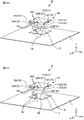
- FIG. 10 is a perspective view of a modified conductor 30F and conductor 30G having extensions 33 extending toward the central portion 31D.
- the four legs 32A-32D of the conductor 30 extend from the corners of the main body 31 along the outer edge 31A.
- the positions and extending directions of the legs 32A to 32D are not limited to this.
- the legs 32A-32D extend from the corners of the main body 31 toward the center 31D.
- the leg portions 32A to 32D extend from the center of the side of the outer edge portion 31A of the body portion 31 toward the central portion 31D.
- the four legs 32A to 32D are positioned rotationally symmetrical to the outer edge 31A of the main body 31. As shown in FIG. Thereby, in the case of the first antenna 20 that receives circularly polarized electromagnetic waves, the capacitance between the conductor 30 and the ground plane 10 can be increased.
- the supporting portion 40 is positioned substantially in the center of the main body portion 31 (the conductor 30) and supports the conductor 30 in a plan view of the XY plane viewed from the +Z direction.
- the supporting structure of the conductor 30 by the supporting portion 40 is not limited to this.
- FIG. 11A and 11A are diagrams showing modifications of the supporting structure of the conductor 30.
- the first antenna 20 in the modification shown in FIG. 11A has an insulator 50 between the front surface of the base plate 10 (ground portion) and the facing surface 34 of the extension portion 33 .
- the support portion 40 is positioned substantially in the center of the main body portion 31 (the conductor 30)
- the extending portion 33 located on the outer edge portion 31A side of the main body portion 31 (conductor 30) may come into contact with the ground plane 10 in some cases. 11A, the first antenna 20 in the modification shown in FIG. Contact with the base plate 10 can be suppressed.
- the support portion 40 supports the extension portion 33 in addition to the main body portion 31> Further, in the first antenna 20 in the modification shown in FIG. 11B, the support portion 40 is positioned between the base plate 10 (ground portion) and the main body portion 31, and the facing surfaces of the base plate 10 and the extension portion 33 34 are spaced apart from each other to support the extending portion 33 . This can also prevent the extending portion 33 from coming into contact with the base plate 10 .
- the support structure for the conductor 30 shown in FIG. 11A or 11B is adopted. can do. According to the supporting structure of the conductor 30 shown in FIG. 11A or 11B, the supporting state of the conductor 30 as a whole can be strengthened.
- the support portion 40 may be formed in a hollow shape. As a result, the occurrence of radio wave loss due to the supporting portion 40 can be reduced.
- FIG. 12A and 12B are diagrams showing modifications of the support structure of the conductor 30.
- FIG. 12A and 12B are diagrams showing modifications of the support structure of the conductor 30.
- the support portion 40 extends from the approximate center of the body portion 31 (conductor 30) to the side of the outer edge portion 31A in a plan view of the XY plane viewed from the +Z direction. It has a cross shape extending in all directions toward the center of the.
- the support portion 40 extends toward the center of the side of the outer edge portion 31A as shown in FIG. 12A, the occurrence of radio wave loss is reduced compared to when the support portion 40 extends to the corner portion of the outer edge portion 31A. can be done.
- the supporting state of the conductor 30 as a whole can be strengthened.
- ⁇ Case in which a plurality of support portions 40 support main body portion 30> In the first antenna 20 in the modified example shown in FIG. 12B, a plurality of support portions 40 are positioned only on the outer edge portion 31A in a plan view of the XY plane viewed from the +Z direction.
- the supporting structure of the conductor 30 shown in FIG. 12B can also strengthen the supporting state of the conductor 30 as a whole.
- the support portion 40 is positioned between the ground plane 10 (ground portion) and the main body portion 31 of the conductor 30 .
- the support portion 40 may be positioned other than between the ground plane 10 and the body portion 31 of the conductor 30 .
- FIG. 13A and 13B are diagrams showing a modification of the supporting structure of the conductor 30.
- FIG. 13A and 13B are diagrams showing a modification of the supporting structure of the conductor 30.
- the cover portion 6 of the first antenna 20 is provided with a protrusion 6A.
- a conductor 30 is hooked on the protrusion 6A so as to be physically separated from the ground plane 10 by a predetermined distance. Therefore, in the first antenna 20 in the modified example shown in FIG. 13, the projection 6A functions as the support portion 40.
- the first antenna 20 of this modified example may not have the projection 6A and the conductor 30 may be adhered to the cover portion 6 .
- the cover portion 6 functions as the support portion 40 .
- the structure may be such that the conductor 30 is suspended from the cover portion 6 by a suspension member.
- the suspension member functions as the support portion 40 .
- the conductor 30 may be fixed to the cover portion 6 by screwing. In this case, the screw serves as the support 40 .
- the first antenna 20 is an antenna that receives radio waves in one frequency band (eg, 1.5 GHz band). However, the first antenna 20 may receive radio waves in multiple (for example, two here) frequency bands.
- FIG. 14A is a plan view of conductor 30 with slot 37.
- FIG. 14B is a plan view of conductor 30 with slot 37 having a meander.
- the main body 31 is provided with four slots 37 along the outer edge 31A.
- the slot 37 is an opening (or hole) formed in the conductor 30 to radiate (or reflect) radio waves of a desired frequency band to be received by the first antenna 20 .
- the frequency band received by the first antenna 20 with the slot 37 includes two frequency bands: a frequency band determined by the outer dimensions of the conductor 30 and a frequency band determined by the length of the slot 37 formed in the conductor 30. will have. This allows the first antenna 20 to receive radio waves in multiple frequency bands. Further, for example, a configuration in which a slot 37, a slit, or the like is provided in the leg portion 32 in FIGS. 5B, 5C, 7B, and 9A may be adopted.
- a notch (slit) instead of an opening formed in the conductor 30 such as the slot 37 may be used. 14A, the slot 37 is provided in the body portion 31, but the slot 37 may be provided in the leg portion 32. FIG. These also allow the first antenna 20 to receive radio waves in a plurality of frequency bands.
- the shape of the slot 37 is not limited to that shown in FIG. 14A.
- a slot 37 having a meander portion is provided in the body portion 31 .
- the slot 37 has a longer overall length and an increased electrical length compared to the slot 37 having no meander portion shown in FIG. 14A. For this reason, the resonance frequency determined by the conductor 30 in the case of the slot 37 having the meander portion shown in FIG. can be done.
- FIG. 15 is a perspective view of the antenna device 100.
- FIG. FIG. 16 is an exploded perspective view of the antenna device 100.
- the antenna device 100 has a first antenna 20 having the characteristics described above and a second antenna 70 different from the first antenna 20 .
- the second antenna 70 is, for example, a planar antenna used for GNSS (Global Navigation Satellite System). Also, the second antenna 70 receives radio waves in a frequency band (eg, 1.2 GHz band) different from radio waves in a frequency band (eg, 1.6 GHz band) receivable by the first antenna 20 .
- the communication standard and frequency band that can be received by the second antenna 70 are not limited to those described above, and other communication standards and frequency bands may be used. Further, both the first antenna and the second antenna may not only receive signals, but may transmit signals or may transmit and receive signals. Also, the second antenna 70 is positioned above the first antenna 20 .
- the second antenna 70 has a dielectric 80 and a radiating element 90 .
- the dielectric 80 is a substantially rectangular plate-like member made of a dielectric material such as ceramic.
- the dielectric 80 is located on the +Z direction side of the conductor 30 of the first antenna 20 (the side opposite to the side of the conductor 30 facing the ground plane 10 (ground portion)).
- the front and back surfaces of the dielectric 80 are parallel to the X and Y directions, the front surface of the dielectric 80 is oriented in the +Z direction, and the back surface of the dielectric 80 is oriented in the -Z direction. directed in the direction.
- a ground conductor (ground conductor plate or ground conductor film) is provided on the back surface side of the dielectric 80 .
- the radiating element 90 is a substantially quadrilateral conductive element that is smaller than the front surface area of the dielectric 80 .
- a radiating element 90 is formed on the front surface of the dielectric 80 .
- the radiating element 90 is located on the +Z direction side of the dielectric 80 (the side opposite to the side of the dielectric 80 facing the conductor 30).
- the normal direction of the radiation surface of the radiation element 90 is the positive direction of the Z axis.
- the radiating element 90 may be provided with slots 37 as shown in Figures 14A and 14B.
- the frequency band (1.6 GHz band) of radio waves received by the first antenna 20 is higher than the frequency band (1.2 GHz band) of radio waves received by the second antenna 70.
- it may be requested to lower the frequency band of the radio waves received by the first antenna 20 .
- it may be requested to shift the frequency band of the radio wave received by the first antenna 20 toward the frequency band of the radio wave received by the second antenna 70 .
- the first antenna 20 of the present embodiment it is possible to easily change to a configuration with a low resonance frequency.
- the resonance frequency of the second antenna 70 instead of the first antenna 20, it is necessary to change the dielectric 80, for example.
- the first antenna 20 can realize an antenna with a low resonance frequency with a simple configuration. For example, in order to lower the resonance frequency of the first antenna 20, it is sufficient to adjust the distance between the extending portion 33 and the ground plane 10 (ground portion).
- the frequency band of the radio waves received by the first antenna 20 is higher than the frequency band of the radio waves received by the second antenna 70, the frequency band of the radio waves received by the first antenna 20 can be easily It can be shifted in a direction closer to the frequency band received by the second antenna 70 .
- the size of the first antenna 20 and the size of the second antenna 70 are substantially the same when viewed from the +Z direction on the XY plane.
- the size of the first antenna 20 and the size of the second antenna 70 may be different, and the size of the first antenna 20 may be larger than the size of the second antenna 70 .
- FIG. 17 is a graph showing an example of return loss in the antenna device 100.
- FIG. 18 is a graph showing an example of the gain in the zenith direction in the antenna device 100.
- the return loss is large in the two frequency bands of 1188.2 MHz and 1568 MHz, and the signal (radio wave) transmission efficiency is high.
- the gain in the zenith direction also has peaks in two frequency bands of 1188.2 MHz and 1568 MHz.
- the antenna device 100 of the present embodiment can satisfactorily receive radio waves in two different frequency bands.
- the antenna device 100 of the present embodiment power is supplied to the second antenna 70 by the power supply unit including the power supply line 36 .
- the first antenna 20 is unpowered. Therefore, the second antenna 70 operates by power feeding, and the first antenna 20 operates by electromagnetic field coupling in relation to the operation of the second antenna 70 .
- both the first antenna 20 and the second antenna 70 may be fed.
- both the first antenna 20 and the second antenna 70 are fed, for example, the electric wave radiated from the second antenna 70 causes electricity to flow in the feed line of the first antenna 20, causing the first antenna 20 to loss may occur in the radio waves radiated by the
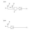
- FIG. 19A and 19B are explanatory diagrams of the feeding method in the antenna device 100.
- FIG. 19A and 19B are explanatory diagrams of the feeding method in the antenna device 100.
- FIG. 19A is a block diagram of an antenna device 100 of a reference example that supplies power to both the first antenna 20 and the second antenna 70.
- FIG. 19B is a block diagram of the antenna device 100 in which only the second antenna 70 is fed and the first antenna 20 is not fed.
- the diplexer 16 is not required, and the problem of deterioration of isolation described above can be avoided. can. Therefore, compared to the case where both the first antenna 20 and the second antenna 70 are fed, the decrease in gain can be suppressed without requiring a separate device such as the diplexer 16 or the like. That is, the number of parts in the antenna device 100 can be reduced.
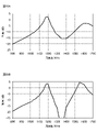
- FIG. 20A and 20B are graphs showing an example of gain in the zenith direction in the antenna device 100.
- FIG. FIG. 20A shows the result of an antenna device 100 feeding both the first antenna 20 and the second antenna 70
- FIG. 20B shows the antenna with the second antenna 70 fed and the first antenna 20 unfed.
- Figure 10 shows the results of device 100;
- the first antenna 20 includes a ground plane 10 (ground portion), a conductor 30 positioned to face the ground plane 10, and a conductor 30 that is physically separated from the ground plane 10 by a predetermined distance. and a support portion 40 .
- the conductor 30 can be brought closer to the ground plane 10 without bringing the conductor 30 and the ground plane 10 into physical contact with each other. can increase the capacity between Therefore, an antenna with a low resonance frequency can be realized with a simple configuration.
- the conductor 30 has a body portion 31 and leg portions 32 . Further, the body portion 31 is positioned so as to face the base plate 10 (ground portion). Further, the leg portion 32 extends from the body portion 31 and is positioned between the base plate 10 and the body portion 31 . As a result, the legs 32 of the conductors 30 can be brought closer to the ground plane 10 without physical contact between the legs 32 of the conductors 30 and the ground plane 10, and the conductors 30 and the ground plane 10 can be brought closer together. can increase the capacity between Therefore, an antenna with a lower resonance frequency can be realized.
- the portion of the leg portion 32 close to the ground plane 10 (ground portion) is electrically coupled to the ground plane 10 .
- the capacitance between the conductor 30 and the ground plane 10 can be increased. Therefore, an antenna with a lower resonance frequency can be realized.
- leg portion 32 is provided on the outer edge portion 31A of the body portion 31 . Therefore, the capacitance between the conductor 30 and the ground plane 10 can be increased. Therefore, an antenna with a lower resonance frequency can be realized.
- the main body portion 31 or the leg portion 32 has at least one of the bent portion 35 and the bent portion 38 .
- the leg portion 32 of the conductor 30 and the ground plane 10 are close to each other. Therefore, the capacitance between the conductor 30 and the ground plane 10 can be increased, and an antenna with a lower resonant frequency can be realized.
- the conductor 30 receives circularly polarized electromagnetic waves and has a plurality of legs 32A to 32D. Furthermore, the plurality of leg portions 32A to 32D are positioned rotationally symmetrical to the outer edge portion 31A of the main body portion 31. As shown in FIG. Thereby, in the case of the first antenna 20 that receives circularly polarized electromagnetic waves, the capacitance between the conductor 30 and the ground plane 10 can be increased. Therefore, an antenna with a lower resonance frequency can be realized.
- leg portion 32 has an extension portion 33 having a facing surface 34 facing the base plate 10 (ground portion).
- the capacitance between the conductor 30 and the ground plane 10 can be increased. Therefore, an antenna with a lower resonance frequency can be realized.
- the conductor 30 has a plurality of legs 32A to 32D. Further, each of the plurality of legs 32A-32D has extensions 33A-33D with facing surfaces 34A-34D. Thereby, the capacitance between the conductor 30 and the ground plane 10 can be increased. Therefore, an antenna with a lower resonance frequency can be realized.
- an insulator 50 is provided between the base plate 10 (ground portion) and the facing surface 34 of the extension portion 33 . Thereby, it is possible to prevent the extending portion 33 from coming into contact with the base plate 10 .
- the support portion 40 is positioned between the base plate 10 (ground portion) and the main body portion 31, and supports the extension portion 33 so that the base plate 10 and the facing surface 34 of the extension portion 33 are separated from each other. .
- the leg portion 32 of the conductor 30 can be brought closer to the ground plane 10 and the contact of the extending portion 33 with the ground plane 10 can be suppressed.
- the support portion 40 is positioned between the base plate 10 (ground portion) and the main body portion 31 . Thereby, the conductor 30 can be brought closer to the ground plane 10 without bringing the conductor 30 and the ground plane 10 into physical contact with each other.
- the conductor 30 has a plurality of legs 32A to 32D, and the support 40 is positioned between two adjacent legs 32. As shown in FIG. As a result, the conductor 30 can be brought closer to the ground plane 10 without physical contact between the conductor 30 and the ground plane 10 while suppressing the effects of radio wave loss and wavelength shortening.
- the supporting portion 40 has at least a center portion 31D in the shape of the conductor 30 and an outer edge portion 31A of the conductor 30 in a plan view seen from a direction (Z direction, vertical direction) perpendicular to the ground plane 10 (ground portion). support one side.
- the conductor 30 can be brought closer to the ground plane 10 without physical contact between the conductor 30 and the ground plane 10 while suppressing the effects of radio wave loss and wavelength shortening.
- the conductor 30 has at least one slot 37 (or slit). This makes it possible to support multiple frequency bands.
- the antenna device 100 includes the first antenna 20 having the characteristics described above and an antenna (second antenna 70) different from the first antenna 20. Furthermore, the second antenna 70 is positioned on the side (+Z direction side) opposite to the side of the conductor 30 facing the ground plane 10 (ground portion), and the side of the dielectric 80 facing the conductor 30 has a radiating element 90 located on the opposite side (+Z direction side). This makes it possible to support multiple frequency bands.
- the antenna device 100 includes a ground plane 10 (ground portion), a first antenna 20 having a conductor 30 positioned to face the ground plane 10 , and a conductive antenna 20 physically separated from the ground plane 10 by a predetermined distance.
- the conductor 30 can be brought closer to the ground plane without bringing the conductor 30 and the ground plane 10 into physical contact with each other. You can increase the capacity between Therefore, an antenna with a low resonance frequency can be realized with a simple configuration. Furthermore, it can support multiple frequency bands.
- the feeding section feeds the second antenna 70 and the first antenna 20 is non-feeding.
- the loss of radio waves can be suppressed, the number of parts can be reduced, and the configuration can be simplified.
- the radiating element 90 has at least one slot 37 (or slit).
- “In-vehicle” in this embodiment means that it can be mounted on a vehicle, so it is not limited to those attached to the vehicle, but also includes those that are brought into the vehicle and used inside the vehicle.
- the antenna device of the present embodiment is used in a "vehicle” which is a vehicle with wheels, it is not limited to this, and can be used for flying objects such as drones, probes, and construction machines without wheels. , agricultural machinery, ships, and other moving bodies.
Landscapes
- Physics & Mathematics (AREA)
- Electromagnetism (AREA)
- Waveguide Aerials (AREA)
- Aerials With Secondary Devices (AREA)
- Details Of Aerials (AREA)
Priority Applications (1)
| Application Number | Priority Date | Filing Date | Title |
|---|---|---|---|
| CN202290000355.9U CN221486824U (zh) | 2021-03-26 | 2022-03-11 | 天线及天线装置 |
Applications Claiming Priority (2)
| Application Number | Priority Date | Filing Date | Title |
|---|---|---|---|
| JP2021052943A JP7677817B2 (ja) | 2021-03-26 | 2021-03-26 | アンテナ及びアンテナ装置 |
| JP2021-052943 | 2021-03-26 |
Publications (1)
| Publication Number | Publication Date |
|---|---|
| WO2022202418A1 true WO2022202418A1 (ja) | 2022-09-29 |
Family
ID=83397145
Family Applications (1)
| Application Number | Title | Priority Date | Filing Date |
|---|---|---|---|
| PCT/JP2022/011082 Ceased WO2022202418A1 (ja) | 2021-03-26 | 2022-03-11 | アンテナ及びアンテナ装置 |
Country Status (3)
| Country | Link |
|---|---|
| JP (1) | JP7677817B2 (https=) |
| CN (1) | CN221486824U (https=) |
| WO (1) | WO2022202418A1 (https=) |
Families Citing this family (2)
| Publication number | Priority date | Publication date | Assignee | Title |
|---|---|---|---|---|
| JP7787320B2 (ja) * | 2022-08-22 | 2025-12-16 | 原田工業株式会社 | アンテナモジュール |
| JP2024172259A (ja) | 2023-05-31 | 2024-12-12 | 日本航空電子工業株式会社 | アンテナエレメント及びアンテナ装置 |
Citations (5)
| Publication number | Priority date | Publication date | Assignee | Title |
|---|---|---|---|---|
| KR100836001B1 (ko) * | 2007-03-05 | 2008-06-09 | 충남대학교산학협력단 | 플레이트 부착형 폴디드 마이크로 스트립 안테나 |
| KR20100020577A (ko) * | 2008-08-13 | 2010-02-23 | 충남대학교산학협력단 | 플레이트 장하를 이용한 미세조절 원형편파 마이크로스트립안테나 |
| KR20100030025A (ko) * | 2008-09-09 | 2010-03-18 | 엘에스엠트론 주식회사 | 소형 패치안테나 |
| KR100981664B1 (ko) * | 2008-06-16 | 2010-09-10 | 충남대학교산학협력단 | 2중 대역 원형편파 마이크로스트립 안테나 |
| WO2018164018A1 (ja) * | 2017-03-08 | 2018-09-13 | 株式会社ヨコオ | スロット付きパッチアンテナ |
Family Cites Families (4)
| Publication number | Priority date | Publication date | Assignee | Title |
|---|---|---|---|---|
| JP2005252585A (ja) * | 2004-03-03 | 2005-09-15 | Alps Electric Co Ltd | 円偏波アンテナ |
| JP6041966B1 (ja) * | 2015-11-19 | 2016-12-14 | 原田工業株式会社 | 複合パッチアンテナ装置 |
| WO2018225537A1 (ja) * | 2017-06-06 | 2018-12-13 | 株式会社村田製作所 | アンテナ |
| WO2019208100A1 (ja) * | 2018-04-27 | 2019-10-31 | 株式会社村田製作所 | アンテナモジュールおよびそれを搭載した通信装置 |
-
2021
- 2021-03-26 JP JP2021052943A patent/JP7677817B2/ja active Active
-
2022
- 2022-03-11 WO PCT/JP2022/011082 patent/WO2022202418A1/ja not_active Ceased
- 2022-03-11 CN CN202290000355.9U patent/CN221486824U/zh active Active
Patent Citations (5)
| Publication number | Priority date | Publication date | Assignee | Title |
|---|---|---|---|---|
| KR100836001B1 (ko) * | 2007-03-05 | 2008-06-09 | 충남대학교산학협력단 | 플레이트 부착형 폴디드 마이크로 스트립 안테나 |
| KR100981664B1 (ko) * | 2008-06-16 | 2010-09-10 | 충남대학교산학협력단 | 2중 대역 원형편파 마이크로스트립 안테나 |
| KR20100020577A (ko) * | 2008-08-13 | 2010-02-23 | 충남대학교산학협력단 | 플레이트 장하를 이용한 미세조절 원형편파 마이크로스트립안테나 |
| KR20100030025A (ko) * | 2008-09-09 | 2010-03-18 | 엘에스엠트론 주식회사 | 소형 패치안테나 |
| WO2018164018A1 (ja) * | 2017-03-08 | 2018-09-13 | 株式会社ヨコオ | スロット付きパッチアンテナ |
Also Published As
| Publication number | Publication date |
|---|---|
| JP2022150365A (ja) | 2022-10-07 |
| JP7677817B2 (ja) | 2025-05-15 |
| CN221486824U (zh) | 2024-08-06 |
Similar Documents
| Publication | Publication Date | Title |
|---|---|---|
| US10186778B2 (en) | Wideband dual-polarized patch antenna array and methods useful in conjunction therewith | |
| US11177578B2 (en) | Antenna device for vehicle | |
| US20150303576A1 (en) | Miniaturized Patch Antenna | |
| CN112368889B (zh) | 天线装置 | |
| CN108352599A (zh) | 适用于基站天线的天线元件 | |
| JP7168752B2 (ja) | スロット付きパッチアンテナ | |
| CN107210541A (zh) | 移动基站天线 | |
| CN106486741B (zh) | 一种空气贴片微带天线 | |
| JP7775226B2 (ja) | パッチアンテナ及び車載用アンテナ装置 | |
| US20200127388A1 (en) | Antenna structure and electronic device | |
| EP1033782B1 (en) | Monopole antenna | |
| JP2002359515A (ja) | M型アンテナ装置 | |
| JP2015111763A (ja) | 偏波ダイバーシチ用アンテナ及び無線通信装置 | |
| WO2022202418A1 (ja) | アンテナ及びアンテナ装置 | |
| US20180123236A1 (en) | Antenna System and Antenna Module With a Parasitic Element For Radiation Pattern Improvements | |
| US20240178554A1 (en) | Vehicular antenna device | |
| US10804609B1 (en) | Circular polarization antenna array | |
| JP6299505B2 (ja) | アンテナ装置 | |
| JP7734492B2 (ja) | パッチアンテナ | |
| JP2002252515A (ja) | アンテナ装置 | |
| JP2002094323A (ja) | 円偏波アンテナ装置 | |
| WO2022138785A1 (ja) | アンテナ装置 | |
| EP3280006A1 (en) | A dual polarized antenna | |
| CN119764840A (zh) | 一种小型化gnss天线 | |
| WO2023127835A1 (ja) | パッチアンテナ及びアンテナ装置 |
Legal Events
| Date | Code | Title | Description |
|---|---|---|---|
| 121 | Ep: the epo has been informed by wipo that ep was designated in this application |
Ref document number: 22775210 Country of ref document: EP Kind code of ref document: A1 |
|
| WWE | Wipo information: entry into national phase |
Ref document number: 202290000355.9 Country of ref document: CN |
|
| NENP | Non-entry into the national phase |
Ref country code: DE |
|
| 122 | Ep: pct application non-entry in european phase |
Ref document number: 22775210 Country of ref document: EP Kind code of ref document: A1 |