WO2022202354A1 - 食品製造方法、食品温調方法、食品製造装置及びプログラム - Google Patents
食品製造方法、食品温調方法、食品製造装置及びプログラム Download PDFInfo
- Publication number
- WO2022202354A1 WO2022202354A1 PCT/JP2022/010518 JP2022010518W WO2022202354A1 WO 2022202354 A1 WO2022202354 A1 WO 2022202354A1 JP 2022010518 W JP2022010518 W JP 2022010518W WO 2022202354 A1 WO2022202354 A1 WO 2022202354A1
- Authority
- WO
- WIPO (PCT)
- Prior art keywords
- temperature
- moving part
- temperature control
- food
- moving
- Prior art date
- Legal status (The legal status is an assumption and is not a legal conclusion. Google has not performed a legal analysis and makes no representation as to the accuracy of the status listed.)
- Ceased
Links
Images








Classifications
-
- A—HUMAN NECESSITIES
- A23—FOODS OR FOODSTUFFS; TREATMENT THEREOF, NOT COVERED BY OTHER CLASSES
- A23L—FOODS, FOODSTUFFS OR NON-ALCOHOLIC BEVERAGES, NOT OTHERWISE PROVIDED FOR; PREPARATION OR TREATMENT THEREOF
- A23L5/00—Preparation or treatment of foods or foodstuffs, in general; Food or foodstuffs obtained thereby; Materials therefor
- A23L5/10—General methods of cooking foods, e.g. by roasting or frying
- A23L5/15—General methods of cooking foods, e.g. by roasting or frying using wave energy, irradiation, electrical means or magnetic fields, e.g. oven cooking or roasting using radiant dry heat
-
- A—HUMAN NECESSITIES
- A21—BAKING; EDIBLE DOUGHS
- A21B—BAKERS' OVENS; MACHINES OR EQUIPMENT FOR BAKING
- A21B1/00—Bakers' ovens
- A21B1/40—Bakers' ovens characterised by the means for regulating the temperature
-
- A—HUMAN NECESSITIES
- A21—BAKING; EDIBLE DOUGHS
- A21B—BAKERS' OVENS; MACHINES OR EQUIPMENT FOR BAKING
- A21B5/00—Baking apparatus for special goods; Other baking apparatus
-
- A—HUMAN NECESSITIES
- A21—BAKING; EDIBLE DOUGHS
- A21B—BAKERS' OVENS; MACHINES OR EQUIPMENT FOR BAKING
- A21B1/00—Bakers' ovens
- A21B1/42—Bakers' ovens characterised by the baking surfaces moving during the baking
- A21B1/48—Bakers' ovens characterised by the baking surfaces moving during the baking with surfaces in the form of an endless band
Definitions
- the present disclosure relates to food manufacturing methods, food temperature control methods, food manufacturing apparatuses, and programs.
- a device uses a baking drum to heat paste-like ingredients such as batter to continuously produce thin-skinned baked foods.
- the skin-like food manufacturing apparatus disclosed in Patent Document 1 includes a baking drum that is heated by a built-in heater and rotates at a low speed, and a heating means that heats the end of the outer peripheral surface of the baking drum. is made uniform.
- the present disclosure has been made in view of the circumstances described above, and aims to provide a technology that is advantageous for stably performing temperature control processing of foodstuffs.
- One aspect of the present disclosure is preparation for temperature control control in which food is continuously applied to the moving part while the moving part cyclically moves in one or more cycles of the moving path without adjusting the temperature of the moving part.
- the food is continuously applied to the moving part while the temperature control process for adjusting the temperature of the moving part based on the target temperature control temperature range is turned on by the temperature control device. and a food temperature control treatment step.
- Another aspect of the present disclosure is temperature control that continuously applies foodstuff to the moving part while the moving part cyclically moves in one or more cycles of the moving path without adjusting the temperature of the moving part.
- the food is continuously fed to the moving portion while the temperature control processing for adjusting the temperature of the moving portion based on the target temperature control temperature range is turned on by the temperature control device. and a food temperature control treatment step to be applied.
- Another aspect of the present disclosure includes a moving section, a temperature control device that adjusts the temperature of the moving section, a foodstuff applying device that applies food to the moving section, and a temperature control device that controls the temperature control device.
- the temperature control device continuously applies foodstuff to the moving part while the moving part cyclically moves along the moving path for one or more cycles without adjusting the temperature of the moving part by the temperature control device.
- the food is placed in the moving part with the temperature control process for adjusting the temperature of the moving part based on the target temperature control temperature range by the temperature control device turned on. It relates to a food manufacturing apparatus that controls a temperature control device so as to perform a food temperature control treatment process that continuously applies the temperature.
- Another aspect of the present disclosure is temperature control that continuously applies foodstuff to the moving part while the moving part cyclically moves in one or more cycles of the moving path without adjusting the temperature of the moving part.
- food is continuously applied to the moving part while the temperature control process is turned on to adjust the temperature of the moving part based on the target temperature control temperature range by the temperature control device. and a program for causing a computer to execute a food temperature control procedure.
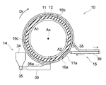
- FIG. 1 is a diagram showing an outline of an example of a food manufacturing apparatus.
- FIG. 2 is a block diagram showing an example of the control configuration of the food manufacturing apparatus.
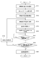
- FIG. 3 is a flow chart showing an example of a food manufacturing method and a food heating method.
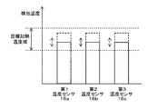
- FIG. 4 shows an example of detection results of the first to third temperature sensors after the moving part is adjusted to the preheating temperature.
- FIG. 5 is a diagram showing an outline of an example of a food manufacturing apparatus for explaining the temperature regulation control preparation process.
- FIG. 6 shows an example of detection results of the first to third temperature sensors when the food manufacturing apparatus is placed in the state shown in FIG.
- FIG. 7 is a diagram showing an outline of an example of a food manufacturing apparatus for explaining the temperature regulation control preparation process.
- FIG. 1 is a diagram showing an outline of an example of a food manufacturing apparatus.
- FIG. 2 is a block diagram showing an example of the control configuration of the food manufacturing apparatus.
- FIG. 3 is a flow chart showing an example of a food
- FIG. 8 shows an example of detection results of the first to third temperature sensors when the food manufacturing apparatus is placed in the state shown in FIG.
- FIG. 9 is a diagram showing an outline of an example of a food manufacturing apparatus for explaining the temperature regulation control preparation process.
- FIG. 10 shows an example of detection results of the first to third temperature sensors when the food manufacturing apparatus is placed in the state shown in FIG.
- FIG. 11 is a diagram showing an outline of an example of a food manufacturing apparatus for explaining the temperature regulation control preparation process.
- FIG. 12 shows an example of detection results of the first to third temperature sensors when the food manufacturing apparatus is placed in the state shown in FIG.
- FIG. 13 is a flow chart of the food manufacturing method and food heating method according to the first modified example.
- FIG. 14 is a cross-sectional view schematically showing an example of a moving part, a heating device, and an outer peripheral cover member according to a second modified example.
- FIG. 15 is a side view schematically showing an example of a moving part, a heating device, and an outer peripheral cover material according to a second modified example.
- FIG. 16 is a side view schematically showing an example of a moving section and a heating device according to a third modified example.
- the following embodiments relate to a food manufacturing apparatus, a food manufacturing method, and a food temperature control method for heating (particularly baking) foodstuffs. is also applicable.
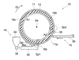
- FIG. 1 is a diagram showing an outline of an example of the food manufacturing apparatus 10.
- FIG. 1 the moving part 11, the heating device (temperature control device) 12, and the temperature sensor 16 (that is, the first temperature sensor 16a to the third temperature sensor 16c) are shown in cross section. etc. are shown in appearance.
- a food manufacturing apparatus 10 shown in FIG. 1 is an apparatus for baking a non-fluid thin-skinned food from a liquid batter having fluidity. and a temperature sensor 16 .
- both the liquid batter and the baked thin-skinned food are referred to as "ingredients.”
- the moving part 11 is configured as a heating cooker (temperature control cooker) for heating ingredients.
- the illustrated moving part 11 is composed of a heating drum rotatable in the direction indicated by the arrow "Dr", and includes an endless heating surface (temperature control surface) 11a constituted by the outer peripheral surface of the heating drum.
- the moving part 11 continuously rotates around the rotation axis Ax.
- the moving part 11 moves between a first area A1 where the moving part 11 moves while the food material 90 is placed on the moving part 11, and a first area A1 where the moving part 11 moves when the food material 90 is not placed on the moving part 11. and the second area A2 repeatedly.
- the heating device 12 is provided as a temperature control device that adjusts the temperature of the moving part 11 , and particularly in the present embodiment, by generating heat to heat the moving part 11 , the temperature of the moving part 11 is adjusted to the heat treatment of the food material 90 .
- the target heating temperature range is a temperature range higher than the ambient temperature (usually room temperature (5° C. to 35° C.)), and is appropriately determined according to the food material 90 .
- a temperature range of 100° C. or higher and 150° C. or lower or a temperature range of 110° C. or higher and 130° C. or lower can be set as the target heating temperature range.
- the target heating temperature range may include a plurality of temperatures, or may include only a specific temperature (that is, a specific target heating temperature).
- the illustrated heating device 12 includes a plurality of electric heaters provided inside the moving part 11 and heats the moving part 11 from the inside.
- a plurality of electric heaters are arranged so as to cover the entire inner peripheral surface of the moving part 11 .
- all the electric heaters included in the heating device 12 are uniformly energized, the heat generation temperature of the heating device 12 is uniformly adjusted throughout the heating device 12, and the moving part 11 is uniformly heated throughout. be done.
- the heating device 12 may be configured such that power supply control is possible for each electric heater, and the heating temperature of each of the plurality of electric heaters included in the heating device 12 may be individually adjusted.
- the electric heater used for the heating device 12 is not limited.
- an on/off-controlled electric heater or an electric heater capable of steplessly controlling power (voltage and/or current) for example, an AC power regulator having a semiconductor such as a thyristor
- the heating device 12 may use other heating means (for example, IH: induction heating).
- the heating device 12 may be fixed to a support (not shown) and immovably provided, or may be movably provided. good.
- the installation position of the heating device 12 is not limited to the illustrated example, and may be embedded in the moving part 11, for example.
- the temperature sensor 16 detects the temperature of the moving part 11 (including the heating surface 11a).
- the temperature sensor 16 shown in FIG. 1 includes a plurality of sensors (ie first temperature sensor 16a to third temperature sensor 16c).
- the first temperature sensor 16a to the third temperature sensor 16c are provided at equal angular intervals around the rotation axis Ax, are partially embedded in the moving portion 11, and are provided so as to rotate together with the moving portion 11.
- FIG. Each of the first temperature sensor 16a to the third temperature sensor 16c detects the temperature of the attachment location of the moving part 11. As shown in FIG.
- the arrangement form and temperature detection method of the first temperature sensor 16a to the third temperature sensor 16c are not limited.
- the first to third temperature sensors 16a to 16c may be located outside the moving section 11 as a whole.
- the first to third temperature sensors 16a to 16c may be contact temperature sensors such as thermocouples, and may be provided so as to contact the inner and/or outer peripheral surfaces of the moving section 11 .
- the first to third temperature sensors 16a to 16c may be composed of non-contact sensors such as infrared sensors, and may be positioned on the inner peripheral surface side and/or the outer peripheral surface side of the moving section 11. FIG.
- the first temperature sensor 16a to the third temperature sensor 16c do not have to move regardless of the rotation of the moving part 11. In this case, the first temperature sensor 16a to the third temperature sensor 16c detect the temperature of the portion of the moving part 11 that passes through the assigned detection spots. Also, the number of temperature sensors 16 is not limited to three, and four or more temperature sensors 16 may be provided, or one or two temperature sensors 16 may be provided.
- the food material application device 14 provides the moving part 11 with the food material 90 corresponding to the set amount of food material application at the food material application spot Sp1.
- the food material 90 applied to the moving part 11 by the food material application device 14 is made of batter having fluidity, and typically contains wheat flour, rice flour and/or eggs.
- the food material 90 may contain other ingredients in addition to or instead of wheat flour, rice flour and/or eggs.
- the temperature of the food material 90 held in the food material applying device 14 and the temperature of the food material 90 when being applied from the food material applying device 14 to the moving part 11 are equal to the environmental temperature (usually room temperature).
- the illustrated foodstuff application device 14 includes a foodstuff hopper 34 , a foodstuff regulator 35 and a foodstuff guide discharge unit 36 .
- the food material 90 is put into the food material hopper 34 mechanically or manually, and the food material hopper 34 can store the food material 90 .
- the food material hopper 34 may have a stirrer (not shown) as necessary, and the food material 90 stored in the food material hopper 34 may be stirred by the stirrer.
- the foodstuff regulator 35 adjusts the amount of foodstuff 90 sent from the foodstuff hopper 34 to the foodstuff guide/discharge unit 36 , and further adjusts the amount of foodstuff 90 applied from the foodstuff guide/discharge unit 36 to the moving part 11 .
- a specific configuration of the food regulator 35 is not limited, and for example, the food regulator 35 includes a gear pump.
- the food material guide/discharge unit 36 has a food material guide path (not shown) that guides the food material 90 sent from the food material hopper 34 through the food material regulator 35 downstream.
- the food material guiding and discharging unit 36 has a food material discharging part 36a for discharging the food material 90 sent through the food material guiding path.
- the foodstuff discharge part 36a may be configured by the end of the foodstuff guide path, or may be provided separately from the foodstuff guide path.
- the food material 90 overflowing from the food material dispensing part 36a is brought into contact with the rotating moving part 11 (especially the heat processing surface 11a) at the food material applying spot Sp1, so that the food material 90 is formed into a thin film on the moving part 11. is granted in the form of
- the food material receiving device 15 receives the food material 90 separated from the moving part 11 at the food material delivery spot Sp2.
- the food material 90 applied to the moving part 11 is heated and baked while moving in the first area A1 from the food material applying spot Sp1 toward the food material delivery spot Sp2 together with the moving part 11, and the food material 90 after baking is transferred to the moving part. 11 to the foodstuff receiving device 15 .
- the food material receiving device 15 shown in the figure includes a food material delivery guide section 38 and a delivery conveyor 39 .
- the foodstuff delivery guide section 38 guides the foodstuff 90 separated from the moving section 11 toward the delivery conveyor 39, and can be configured by, for example, a scraper.
- the delivery conveyor 39 conveys the placed foodstuff 90 toward the rear stage.
- the delivery conveyor 39 shown in FIG. 1 is composed of an endless belt conveyor.
- FIG. 2 is a block diagram showing an example of the control configuration of the food manufacturing apparatus 10. As shown in FIG.
- the food manufacturing apparatus 10 of this embodiment includes an integrated controller (control device) 50.
- An integrated controller 50 that controls other devices included in the food manufacturing apparatus 10 includes a foodstuff application controller 51 , a heating controller (temperature control device) 52 , a movement controller 53 and a storage unit 54 .
- the food material application controller 51 controls driving of the food material application device 14 (for example, the food material regulator 35).
- a heating controller 52 controls the driving of the heating device 12 .
- the movement controller 53 controls driving of a movement driving device 44 such as a motor that provides power to the movement section 11 .
- the foodstuff application controller 51, the heating controller 52 and/or the movement controller 53 may comprise an inverter, and the inverter may adjust the frequency of the drive current applied to each controlled object.
- the foodstuff application controller 51, heating controller 52, and movement controller 53 are connected to each other, and are also connected to the temperature sensor 16, the user interface 20, and the storage unit 54.
- Each of the foodstuff application controller 51, the heating controller 52, and the movement controller 53 can transmit and receive data to and from other connected controllers, the temperature sensor 16, the user interface 20, and the storage unit .
- the user interface 20 functions as a user input section for inputting various data and commands by the user, and also functions as a user output section for outputting various data (for example, status data) in the food manufacturing apparatus 10 .
- the user may input, for example, a set amount of food material to be applied to the user interface 20, which indicates the amount of the food material 90 to be applied from the food material applying device 14 to the moving section 11.
- FIG. Also, the user can check various data related to the food manufacturing apparatus 10 via the user interface 20 .
- the storage unit 54 stores information such as various data (including programs), and is composed of a storage device based on magnetic, optical, magneto-optical, or any other writing and reading method. Devices connected to the storage unit 54 read out and use information stored in the storage unit 54, update information stored in the storage unit 54, or add new information as necessary. It is possible to store it in the storage unit 54 .
- the integrated controller 50 of this example collectively includes a foodstuff application controller 51, a heating controller 52, a movement controller 53, and a storage unit 54, which are provided separately from each other.
- the integrated controller 50 may further include other controllers, storage units, and the like, which are not shown. Any two or more controllers included in the integrated controller 50 may be realized by a common control device. Also, a single control device may function as food application controller 51 , heating controller 52 and movement controller 53 . Further, in the example shown in FIG. 2, the storage unit 54 is provided separately from other devices, but the storage unit 54 may be provided as part of other devices (for example, various controllers, etc.).
- the integrated controller 50 may control the driving of devices not shown in FIG. 2, for example, the driving of the foodstuff receiving device 15 (for example, the delivery conveyor 39).
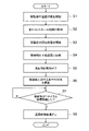
- FIG. 3 is a flow chart showing an example of a food manufacturing method and a food heating method.
- the heating process (temperature control process) of the foodstuff 90 using the food manufacturing apparatus 10 is started in a state where the entire moving part 11 has the same temperature (typically the environmental temperature (for example, room temperature)).
- the environmental temperature for example, room temperature
- the temperature sensors 16 start detecting the temperature of the moving part 11 (S1 in FIG. 3).
- the temperature sensor 16 continuously or intermittently detects the temperature of the moving part 11 and transmits the detection result to the integrated controller 50 (for example, the heating controller 52).
- the temperature detection by the temperature sensor 16 and the transmission of the detection result are continuously performed throughout the entire process of the food manufacturing method and the food heating method.
- food control information input by the user via the user interface 20 is acquired by the integrated controller 50 (for example, the food addition controller 51, the heating controller 52 and/or the movement controller 53) (S2).
- the food material control information includes information about the set amount of food material that directly or indirectly indicates the amount of food material 90 to be applied from the food material applying device 14 to the moving unit 11 .
- the amount of the food material 90 applied to the moving unit 11 per unit time and/or the thickness of the food material 90 placed on the moving unit 11 can be set as the food material application setting amount.
- the food control information may include information other than the set amount of food to be added, and may include, for example, information regarding the constituent materials and/or water content of the food 90 .
- the movement controller 53 drives the movement driving device 44, and the rotational movement of the movement section 11 is started (S3).
- a specific aspect of the rotational movement of the moving part 11 is not limited.
- the moving part 11 may be rotated at a predetermined rotation speed under the control of the movement controller 53 .
- the movement controller 53 may adaptively determine the rotational speed of the moving part 11 based on the set amount of food material to be applied, the detection result of the temperature sensor 16 (that is, the temperature of the moving part 11) and/or other information.
- the movement controller 53 may control the movement driving device 44 so as to rotate the moving section 11 at the rotational speed thus determined.
- the heating device 12 starts to be driven under the control of the heating controller 52, and the moving part 11 is heated by the heating device 12 and adjusted to the preheating temperature (S4: preheating step).
- the heating controller 52 controls the heating device 12 according to the temperature of the moving portion 11 detected by the temperature sensor 16 , and controls the degree of heating of the moving portion 11 by the heating device 12 according to the actual temperature of the moving portion 11 . change.
- the calorific value (energization amount) of all the electric heaters included in the heating device 12 is uniformly adjusted.
- the heating device 12 heats the moving part 11 based on the feedback control method.
- a specific mode of heating the moving part 11 by the heating device 12 is not limited.
- FIG. 4 shows an example of detection results of the first temperature sensor 16a to the third temperature sensor 16c after the moving part 11 is adjusted to the preheating temperature.
- the entire moving section 11 is uniformly heated by the heating device 12 without the foodstuff 90 being applied to the moving section 11 .
- the temperature of the entire moving portion 11 uniformly rises from the environmental temperature toward the target preliminary temperature range.
- the heating device 12 stops heating the entire moving part 11 and performs preliminary temperature control. The process ends.
- the entire moving section 11 is heated in the same or substantially the same manner, and the detection results of the first temperature sensor 16a to the third temperature sensor 16c are the same or substantially the same.
- Whether or not the temperature of the moving part 11 has reached the target preliminary temperature range may be determined based on the average value of the temperatures detected by the first temperature sensor 16a to the third temperature sensor 16c. It may be performed based on whether the temperature detected by the temperature sensor has reached the target preliminary temperature range.
- the target preliminary temperature range may include a plurality of temperatures, or may include only a specific temperature (that is, a specific preliminary temperature).
- the preliminary temperature is the temperature of the target temperature control temperature range described later or the temperature higher than the target temperature control temperature range (that is, the temperature equal to or higher than the target temperature control temperature range).
- the food material 90 applied from the food material applying device 14 to the moving part 11 while the heating of the moving part 11 by the heating device 12 is stopped is completely baked before reaching the food material delivery spot Sp2. is the preliminary temperature (target preliminary temperature range). Therefore, the preliminary temperature (target preliminary temperature range) is appropriately determined according to the heating characteristics of the food material, the characteristics of the moving part 11 (for example, heat storage characteristics), and the capacity of the heating device 12 .
- a partial temperature range including the upper limit temperature in the target heating temperature range is set as the target preliminary temperature range. You can set it in the area.
- the temperature control preparation process is performed under the control of the integrated controller 50 . That is, under the control of the heating controller 52, the "temperature control process for adjusting the temperature of the moving part 11 with reference to the target temperature control temperature range by the heating device 12" is turned off (S5). Also, under the control of the food material applying controller 51, the food material applying device 14 starts to apply the food material 90 to the moving part 11 (S6). Then, under the control of the movement controller 53, the movement section 11 is cyclically moved for one cycle (S7).
- the temperature control process is turned off and the temperature of the moving part 11 is not adjusted, and the food material 90 is continuously applied to the moving part 11 while the moving part 11 is being moved. Move one cycle on the movement path.
- the “state in which the temperature control process is turned off” can refer to a general state in which the temperature of the moving section 11 is not adjusted.
- the state in which the integrated controller 50 (for example, the heating controller 52) itself does not perform the temperature control process corresponds to the "state in which the temperature control process is turned off", but other states also correspond to the "state in which the temperature control process is not performed.” off state”.
- a state in which the heating device 12 is powered off and a state in which the heating controller 52 and the heating device 12 are not connected can also correspond to the "state in which the temperature control process is off.”
- the "temperature control process OFF state” and/or the “temperature control process ON state” may be created by the integrated controller 50 (for example, the heating controller 52), or may be created by the operator. .
- active temperature adjustment of the moving part 11 (that is, active heating and cooling of the moving part 11) is not performed.
- the food material 90 is continuously applied to the moving part 11 in a state of having a temperature equal to or higher than the temperature control range.
- the food material 90 applied to the moving part 11 at the food material applying spot Sp1 is baked before reaching the food material sending spot Sp2, and is removed from the moving part 11 by the food material sending guide part 38 at the food material sending spot Sp2. It is peeled off and handed over to the foodstuff receiving device 15 . In the portion of the moving part 11 to which the food material 90 is applied at the food material application spot Sp1, the food material 90 is removed at the food material delivery spot Sp2. is ready to be granted.
- step (S4) the moving section 11 is sufficiently preheated. That is, the above target preliminary temperature range (preliminary temperature) is set in consideration of the temperature drop of the moving part 11 and the target temperature control temperature range in the temperature control preparation process (S5 to S7), and the moving part 11 is set in the preliminary temperature control process. is appropriately adjusted to the target preliminary temperature range (preliminary temperature). Setting such a target pre-temperature range (pre-temperature) may be performed by the heating controller 52 . The heating controller 52 may set the target pre-temperature range (pre-temperature) based on information input via the user interface 20 .
- the temperature of the moving part 11 is prevented from becoming lower than the target temperature control temperature range, and the food material 90 provided to the moving part 11 is baked at the food material delivery spot Sp2. is recovered from the moving unit 11 in the state shown in FIG.
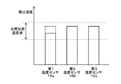
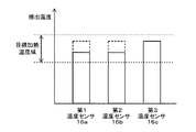
- FIGS. 5, 7, 9 and 11 are diagrams showing an outline of an example of the food manufacturing apparatus 10 for explaining the temperature regulation control preparation process.
- 6, 8, 10 and 12 show the first temperature sensor 16a to the third temperature sensor when the food manufacturing apparatus 10 is placed in the states shown in FIGS. 5, 7, 9 and 11, respectively.
- An example of the detection result of 16c is shown.
- the foodstuff 90 discharged from the foodstuff applying device 14 (foodstuff discharger 36a) in the temperature adjustment control preparation process adheres to the heat-treated surface 11a of the moving part 11 in a thin film and lowers the temperature of the moving part 11.
- the temperature of the portion of the moving portion 11 corresponding to the first temperature sensor 16a is the temperature (preheating temperature) at the beginning of the temperature control preparation process. but within the target heating temperature range (see FIG. 6).
- the temperature of the portion of the moving section 11 corresponding to the first temperature sensor 16a and the second temperature sensor 16b is the preheating temperature. but within the target heating temperature range.
- the temperature of the portion of the moving portion 11 corresponding to the first temperature sensor 16a may be slightly lower than the temperature of the portion corresponding to the second temperature sensor 16b.
- the heat energy stored in the moving part 11 is much larger than the heat energy used for the heat treatment of the foodstuff 90 .
- the thermal conductivity of the moving part 11 is high, the temperature difference between the regions of the moving part 11 is reduced in a short time. Therefore, in the state shown in FIG. 7, the temperature of the portion of the moving portion 11 corresponding to the first temperature sensor 16a is approximately or substantially the same as the temperature of the portion corresponding to the second temperature sensor 16b.
- the temperature detected by the third temperature sensor 16c drops to the same level as the temperatures detected by the first temperature sensor 16a and the second temperature sensor 16b (see FIG. 10).
- the temperatures of the portions of the moving section 11 corresponding to the first temperature sensor 16a to the third temperature sensor 16c are the preheating temperature. but within the target heating temperature range.
- the temperature of the portion of the moving portion 11 corresponding to the first temperature sensor 16a may be slightly lower than the temperature of the portion corresponding to the second temperature sensor 16b.
- the temperature of the portion corresponding to the second temperature sensor 16b may be slightly lower than the temperature of the portion corresponding to the third temperature sensor 16c.
- the temperatures of the portions corresponding to the first temperature sensor 16a to the third temperature sensor 16c in the moving portion 11 are substantially the same or substantially the same.
- the temperature control preparation process is continued until "a portion to which the food material 90 has not adhered even once in the temperature control control preparation process" disappears from the moving part 11 (especially the heat processing surface 11a).
- the moving part 11 makes exactly one rotation, and the temperature control preparation process is continued until the food material 90 from the food material application device 14 is applied to the entire heating surface 11a (Fig. 11).
- the food temperature control process is performed under the control of the integrated controller 50 . That is, after the temperature control preparation step, the temperature control process is turned on under the control of the heating controller 52 (S8 in FIG. 3).
- the food material 90 is continuously applied to the moving part 11 under control.
- the rotational movement of the moving part 11 and the application of the foodstuff 90 to the moving part 11 are similarly performed in the temperature regulation control preparation process and the foodstuff temperature regulation processing process. Therefore, it is possible to seamlessly shift from the temperature control control preparation process to the food temperature control processing process without interrupting the rotational movement of the moving part 11 and without interrupting the application of the food material 90 to the moving part 11 . .
- the moving part 11 is placed in a state where the whole is kept at substantially the same temperature while the foodstuff 90 is supplied from the foodstuff applying device 14 . Therefore, in the food material temperature control process, the temperature control process for uniformly adjusting the temperature of the entire moving part 11 is turned on while the entire moving part 11 has substantially the same temperature. As a result, the temperature of the entire moving part 11 can be adjusted to the target heating temperature range while preventing a large temperature difference between regions of the moving part 11, and the heat treatment of the food material 90 by the moving part 11 can be stabilized. can be performed in a consistent and uniform manner.
- the moving unit 11 After the temperature control process is switched from the off state to the on state while the moving unit 11 has the temperature in the target temperature control temperature range, the moving unit 11 The food material 90 is continuously applied to .
- the food material 90 can be heat-treated at an appropriate temperature by the moving part 11 from the beginning of the food material temperature control process.
- the moving part 11 Even if the temperature of the moving part 11 changes with the progress of the food material temperature control process, the moving part 11 is heated by the heating device 12 as necessary while the temperature control process is on. Therefore, the temperature of the entire moving part 11 can be continuously maintained within the target heating temperature range suitable for the heat treatment of the foodstuff 90 .
- the heating device 12 does not necessarily continue to actively heat the moving portion 11 while the temperature control process is on. That is, the heating device 12 does not need to heat the moving part 11 while the moving part 11 has a temperature suitable for the heat treatment of the foodstuff 90 .
- the heating device 12 positively moves the moving part 11 even when the temperature of the moving part 11 is within the target heating temperature range. may be heated to In this case, the heating device 12 appropriately adjusts the heating of the moving part 11 so that the temperature of the moving part 11 does not exceed the target heating temperature range, and temporarily stops the heating of the moving part 11 as necessary. good too.
- the heating device 12 may heat the moving part 11 by generating heat from the beginning of the food temperature control process, or continue to heat the moving part 11 without generating heat even at the beginning of the food temperature control process. It doesn't have to be.
- the moving part 11 since the temperature of the moving part 11 is in the target temperature control temperature range at the beginning of the food temperature control processing process, the moving part 11 is in a state in which the food material 90 can be appropriately heat-treated.
- the heating of the moving part 11 by the heating device 12 may be started in a state where the temperature of the moving part 11 is out of the target temperature control temperature range.
- the temperature of the moving portion 11 may be started in the target temperature control temperature range.
- the heating device 12 may start generating heat when the temperature of the moving part 11 (that is, the temperature detected by the temperature sensor 16) is lower than the threshold temperature within the target temperature control temperature range.
- the heating device 12 when the temperature of the moving part 11 (the temperature detected by the temperature sensor 16) at the beginning of the food temperature control process is lower than the threshold temperature, the heating device 12 generates heat from the beginning of the food temperature control process. to actively heat the moving part 11 .
- the heating device 12 does not generate heat at the beginning of the food temperature control process. Therefore, the moving part 11 is not heated. In this case, the heating device 12 generates heat to actively heat the moving part 11 after the temperature of the moving part 11 gradually decreases to be lower than the threshold temperature after the start of the food temperature control process.
- the heating device 12 starts to generate heat when the temperature of the moving part 11 (the temperature detected by the temperature sensor 16) is lower than the target temperature control temperature range, the temperature of the moving part 11 is Since the temperature is within the target temperature control temperature range, the heating device 12 does not heat the moving part 11 .
- the moving part 11 (especially A food material 90 is applied to the entire heat-treated surface 11a).
- the food material 90 is continuously applied to the moving part 11, and the temperature of the moving part 11 can be made substantially uniform throughout.
- the food temperature control process can be started in a state in which a large temperature difference is unlikely to occur between the regions of the moving part 11 and the food material 90 can be applied to the moving part 11.
- the heat treatment of the food material 90 can be performed stably and uniformly.
- the moving unit 11 moves along the moving path for only one cycle. It may be moved cyclically for one or more cycles.
- the moving unit 11 may cyclically move N cycles ("N" is an integer equal to or greater than 1) while continuously applying the food material 90 in the temperature control preparation process.
- N is an integer equal to or greater than 1
- the same amount of foodstuff 90 is evenly applied to the heat-treated surface 11a of the moving part 11 over the entire surface, and a large temperature difference between regions of the moving part 11 can be effectively prevented.
- the temperature of the moving portion 11 decreases as the food material 90 is applied.
- the temperature of the moving part 11 tends to be uneven. For example, if the entire moving portion 11 is heated based on the temperature of the portion of the moving portion 11 that has locally decreased in temperature due to the application of the food material 90, the portion of the moving portion 11 to which the food material 90 is not applied is excessively heated. will be heated to As a result, a large temperature difference occurs between the areas of the moving part 11 (that is, between the area to which the food material 90 is applied and the area to which the food material 90 is not applied).
- the heat treatment will be greatly uneven, and it will be difficult to perform the heat treatment of the food material 90 stably and uniformly.
- the food material 90 with uneven heating may require additional heat treatment, may be diverted to a different use than the intended use, or may be finally discarded.
- the foodstuff 90 that has been subjected to an inappropriate heat treatment may cause problems in subsequent treatments, resulting in serious harm.
- the heating device 12 uniformly heats the entire moving portion 11 as in the present embodiment, the moving portion 11 as a whole is heated from a state in which a large temperature difference occurs between regions of the moving portion 11 . It usually takes a long time to adjust to a uniform temperature suitable for heat treatment. As the time required to adjust the entire moving part 11 to a uniform temperature suitable for heat treatment increases, the amount of “heat-treated foodstuff 90 with uneven heating” also increases.
- the food manufacturing apparatus 10 and the food manufacturing method (food temperature control method) of the present embodiment described above it is possible to effectively suppress the temperature unevenness of the moving part 11 with a simple device configuration. Heat treatment can be performed stably and uniformly. Further, according to the present embodiment, since it is possible to suppress the occurrence of temperature unevenness in the moving section 11, the processing itself for reducing the temperature unevenness of the moving section 11 may be unnecessary. As a result, it is possible to promote "shortening of the time" and "reduction of the amount of the food material 90 subjected to inappropriate heat processing" required to adjust the food manufacturing apparatus 10 to a state suitable for the heat processing of the food material 90. is.
- the moving part 11 By dividing the moving part 11 (especially the heat treatment surface 11a) into a plurality of zones and assigning a plurality of heating devices to each of the plurality of zones, it is possible to control the temperature of the moving part 11 in units of zones. In this case, it is possible to reduce temperature unevenness between regions of the moving part 11 on a zone-by-zone basis, but there is a tendency that the number of apparatuses increases and the heating control becomes complicated. As a result, the required installation space for the device increases, the labor required for the maintenance of the device increases, and the possibility of trouble occurring increases.
- the food manufacturing apparatus 10 and the food manufacturing method (food temperature control method) of the present embodiment described above although the temperature of the moving part 11 cannot be controlled in units of zones, an increase in the number of apparatuses can be suppressed. Heating control can also be simplified. As a result, the space-saving design of the apparatus is possible, the labor required for the maintenance of the apparatus can be reduced, and the possibility of trouble occurrence can be kept low.
- FIG. 13 is a flow chart of the food manufacturing method and food heating method according to the first modified example.
- temperature differences between multiple locations on the moving part 11 may be considered. That is, in the food temperature control process of this modification, the temperature control process is changed from the off state to the on state while the temperature difference detected by the temperature sensor 16 at a plurality of locations of the moving part 11 is included in the allowable temperature range. can be switched to
- temperature detection of the moving part 11 is started (S11 in FIG. 13), food control information is acquired (S12), and rotational movement of the moving part 11 is started ( S13), a preliminary temperature control step is performed (S14).
- the temperature control process is turned off (S15), and the food material 90 is started to be applied to the moving part 11 (S16), as in the above-described embodiment.
- the moving unit 11 is cyclically moved for one cycle (S17).
- the integrated controller 50 (for example, the heating controller 52) ensures that the difference between the detected temperatures of the first temperature sensor 16a to the third temperature sensor 16c is within the allowable temperature range. It is determined whether or not (S18).
- the temperature control process is turned on (S20 ), the food temperature control process is started.
- the temperature unevenness reduction process for reducing the temperature unevenness of the moving part 11 is performed (S19).
- the specific processing content of the temperature unevenness reduction processing is not limited.
- the temperature unevenness of the moving part 11 may be reduced by letting the food 90 not be applied to the moving part 11 for a certain period of time.
- a cooling device (not shown) on a portion of the moving part 11 where the temperature is locally high, or by locally applying the food material 90 from the food material applying device 14 , the temperature unevenness of the moving part 11 may be reduced.
- Locations of the moving part 11 where the temperature is locally high are specified by the integrated controller 50 (eg, the heating controller 52) according to the position of the temperature sensor with a higher detected temperature than the others among the plurality of temperature sensors 16a to 16c, for example.
- the configuration of the cooling device and the cooling method are not limited.
- the cooling device may apply a cooling medium (for example, cooling water or cooling air) to the heat-treated surface 11a in the second area A2.
- the food temperature control process is started in a state where the temperature difference between the areas of the moving part 11 is within the allowable temperature range. Therefore, in the food material temperature control process, the food material 90 can be heat-processed more reliably by the moving part 11 with less temperature unevenness, and the food material temperature control process can be performed more stably and uniformly.
- FIG. 14 is a cross-sectional view schematically showing an example of the moving part 11, the heating device 12, and the outer peripheral cover material 26 according to the second modification.
- FIG. 15 is a side view schematically showing an example of the moving part 11, the heating device 12, and the outer peripheral cover material 26 according to the second modification.
- the heat treatment surface 11 a of the moving part 11 may be configured by the inner peripheral surface of the heating drum that constitutes the moving part 11 .
- the food material 90 applied from the food material application device 14 to the moving part 11 may contain solid matter.
- the heating device 12 is provided so as to cover the outer peripheral surface of the cylindrical moving portion 11
- the outer peripheral cover material 26 is provided so as to cover the outer peripheral surface of the heating device 12
- the outer cover member 26 is made of a heat insulating member that reduces radiant heat from the heating device 12 .
- the foodstuff applying device 14 (see FIG. 1) provides foodstuff 90 inside the moving part 11 , and the moving part 11 is heated from the outside by the heating device 12 . As a result, the food material 90 is heated and cooked on the heat processing surface 11 a formed by the inner peripheral surface of the moving portion 11 .
- the cylindrical moving portion 11 may be inclined in the height direction.
- openings may be formed at both end portions of the moving portion 11 in the extending direction of the rotation axis Ax.
- a region in the vicinity of one end opening of the heat-treated surface 11a (that is, the inner peripheral surface) of the moving portion 11 may be defined as the "food material applying spot Sp1 where the food material 90 is applied to the moving part 11".
- the area near the other end opening of the heating surface 11a may be defined as the "food delivery spot Sp2 where the cooked food 90 leaves the moving part 11".
- a convex portion (not shown) protruding from the heating surface 11a can guide the food material 90 from the food material applying spot Sp1 toward the food material delivery spot Sp2 as the moving part 11 rotates (for example, spirally extending convex portion) may be provided on the heat-treated surface 11a.
- the integrated controller 50 (especially the heating controller 52) controls the heating device 12 so as to perform the temperature adjustment control preparation process and the food temperature adjustment process, thereby stably and uniformly cooking the food material 90. can be done systematically.
- FIG. 16 is a side view schematically showing an example of the moving part 11 and the heating device 12 according to the third modified example.
- the moving section 11 may be configured by a belt conveyor.
- the food material 90 applied from the food material applying device 14 to the moving part 11 may contain solid matter.
- the moving part 11 shown in FIG. 16 is composed of an endless metal belt (for example, a wire mesh belt or a steel belt) supported in tension by two drive shafts 28 .
- a surface of the moving portion 11 facing outward constitutes a heat treatment surface 11a.
- the heating device 12 is provided inside the moving part 11 .
- the foodstuff applying device 14 of this example places a foodstuff 90 (for example, a solid foodstuff) on the heating surface 11 a from above, and the moving part 11 is heated from the inside by the heating device 12 .
- the integrated controller 50 (especially the heating controller 52) controls the heating device 12 so as to perform the temperature control preparation process and the food temperature control process, so that the food material 90 is cooked stably and uniformly. can be done systematically.
- a cooling device (not shown) may be provided instead of the heating device 12 .
- a cooling device driven under the control of the integrated controller 50 (for example, a cooling controller (not shown)
- temperature control processing ie, cooling processing
- of the foodstuff 90 may be performed.
- a heat insulating member may be provided between the foodstuff application device 14 (for example, the foodstuff guide/discharge unit 36) and the heating device 12 to reduce the influence of radiant heat on the foodstuff application device 14.
- the heat insulating member can include general members capable of reducing radiant heat, and can also include so-called heat shield members that reflect radiant heat.
- the food material 90 to which the food manufacturing apparatus 10, the food manufacturing method, and the food temperature control method described above can be applied is not limited.
- the food manufacturing apparatus 10, the food manufacturing method, and the food temperature control method are capable of temperature control cooking (that is, heat cooking and/or cooling cooking) of any type of food material 90.
- FIG. Also, the material state of the food material 90 during temperature control cooking is not limited.
- the food manufacturing apparatus 10, the food manufacturing method, and the food temperature control method can perform temperature-controlled cooking of liquid food 90, solid food 90, and food 90 in other states.
- Batter which is a raw material for baked thin-skinned foods (skins used for shumai, dumplings, spring rolls, burritos, tacos, crepes, etc.), and other irregular-shaped paste-like foodstuffs with fluidity (cheese, etc.) are used as foodstuffs 90 It may be applied to the moving part 11 from the food applying device 14 .
- a solid food material to be cooked (for example, hamburger steak) may be applied as the food material 90 from the food material applying device 14 to the moving section 11 .
- Fluid foodstuffs to be cooled and cooked for example, chocolate may be applied as foodstuffs 90 from the foodstuff applying device 14 to the moving part 11 .
- the technical categories that embody the above technical ideas are not limited.
- the above technical idea may be embodied by a computer program for causing a computer to execute one or more procedures (steps) included in the above method.
- the above technical idea may be embodied by a computer-readable non-transitory recording medium in which such a computer program is recorded.
- a food temperature control treatment process to A food manufacturing method comprising:
- a food temperature control treatment process to Food temperature control method including.
- the temperature control device is A temperature at which the food material is continuously applied to the moving part while the moving part cyclically moves on the moving path for one or more cycles without adjusting the temperature of the moving part by the temperature control device.
- an adjustment control preparation step After the temperature control control preparation step, the foodstuff is continuously fed to the moving part while the temperature control process for adjusting the temperature of the moving part based on the target temperature control temperature range is turned on by the temperature control device.
- a control device for controlling a food manufacturing apparatus comprising a moving part, a temperature control device that adjusts the temperature of the moving part, and a foodstuff applying device that applies foodstuff to the moving part, A temperature at which the food material is continuously applied to the moving part while the moving part cyclically moves on the moving path for one or more cycles without adjusting the temperature of the moving part by the temperature control device.
- a tuning control preparation step After the temperature control control preparation step, the foodstuff is continuously fed to the moving part while the temperature control process for adjusting the temperature of the moving part based on the target temperature control temperature range is turned on by the temperature control device.
Landscapes
- Life Sciences & Earth Sciences (AREA)
- Engineering & Computer Science (AREA)
- Food Science & Technology (AREA)
- Health & Medical Sciences (AREA)
- Nutrition Science (AREA)
- Chemical & Material Sciences (AREA)
- Polymers & Plastics (AREA)
- General Preparation And Processing Of Foods (AREA)
Priority Applications (3)
| Application Number | Priority Date | Filing Date | Title |
|---|---|---|---|
| US18/283,755 US20240180208A1 (en) | 2021-03-25 | 2022-03-10 | Food manufacturing method, food temperature-regulating method, food manufacturing apparatus and program |
| CN202280023829.6A CN117042615A (zh) | 2021-03-25 | 2022-03-10 | 食品制造方法、食品调温方法、食品制造装置以及程序 |
| JP2023508981A JP7778134B2 (ja) | 2021-03-25 | 2022-03-10 | 食品製造方法、食品温調方法、食品製造装置及びプログラム |
Applications Claiming Priority (2)
| Application Number | Priority Date | Filing Date | Title |
|---|---|---|---|
| JP2021-052217 | 2021-03-25 | ||
| JP2021052217 | 2021-03-25 |
Publications (1)
| Publication Number | Publication Date |
|---|---|
| WO2022202354A1 true WO2022202354A1 (ja) | 2022-09-29 |
Family
ID=83394952
Family Applications (1)
| Application Number | Title | Priority Date | Filing Date |
|---|---|---|---|
| PCT/JP2022/010518 Ceased WO2022202354A1 (ja) | 2021-03-25 | 2022-03-10 | 食品製造方法、食品温調方法、食品製造装置及びプログラム |
Country Status (4)
| Country | Link |
|---|---|
| US (1) | US20240180208A1 (https=) |
| JP (1) | JP7778134B2 (https=) |
| CN (1) | CN117042615A (https=) |
| WO (1) | WO2022202354A1 (https=) |
Citations (3)
| Publication number | Priority date | Publication date | Assignee | Title |
|---|---|---|---|---|
| JPS54143582A (en) * | 1978-04-28 | 1979-11-08 | Daiei Giken Kk | Skin like food making apparatus |
| JPS60172252A (ja) * | 1984-02-17 | 1985-09-05 | 大英技研株式会社 | 皮状焼成品製造装置 |
| JP2004008117A (ja) * | 2002-06-07 | 2004-01-15 | Meiji Seika Kaisha Ltd | 焼成物の製造方法及び焼成装置 |
Family Cites Families (10)
| Publication number | Priority date | Publication date | Assignee | Title |
|---|---|---|---|---|
| CH554641A (fr) * | 1971-04-07 | 1974-10-15 | Etud Sarl | Machine automatique a fabriquer les crepes. |
| FR2232175A5 (https=) * | 1973-06-01 | 1974-12-27 | Etud Sa | |
| JPH01235563A (ja) * | 1988-03-15 | 1989-09-20 | Kibun Kk | ちくわ製造装置 |
| JP3005043U (ja) * | 1994-06-08 | 1994-12-06 | 株式会社大野製作所 | バウムクーヘン焼成用具 |
| JP2001017064A (ja) * | 1999-07-05 | 2001-01-23 | Daiei Giken Kk | 皮状食品の製造方法及び製造装置 |
| NZ546385A (en) * | 2003-09-05 | 2009-11-27 | Mrs Mac S Pty Ltd | Method for maintaining hot food and/or heating cold food by monitoring the surface on which the food is placed |
| CN1857109A (zh) * | 2005-04-30 | 2006-11-08 | 太阳化学株式会社 | 片状食品及其制造方法 |
| JP4577855B2 (ja) * | 2009-02-05 | 2010-11-10 | 株式会社清月 | 焼菓子の製造方法 |
| US10624353B1 (en) * | 2015-03-12 | 2020-04-21 | John Langley | Pizza oven |
| CN110513732A (zh) * | 2019-08-28 | 2019-11-29 | 广东美的厨房电器制造有限公司 | 食物处理装置、控制方法、系统及存储介质 |
-
2022
- 2022-03-10 US US18/283,755 patent/US20240180208A1/en active Pending
- 2022-03-10 CN CN202280023829.6A patent/CN117042615A/zh active Pending
- 2022-03-10 JP JP2023508981A patent/JP7778134B2/ja active Active
- 2022-03-10 WO PCT/JP2022/010518 patent/WO2022202354A1/ja not_active Ceased
Patent Citations (3)
| Publication number | Priority date | Publication date | Assignee | Title |
|---|---|---|---|---|
| JPS54143582A (en) * | 1978-04-28 | 1979-11-08 | Daiei Giken Kk | Skin like food making apparatus |
| JPS60172252A (ja) * | 1984-02-17 | 1985-09-05 | 大英技研株式会社 | 皮状焼成品製造装置 |
| JP2004008117A (ja) * | 2002-06-07 | 2004-01-15 | Meiji Seika Kaisha Ltd | 焼成物の製造方法及び焼成装置 |
Also Published As
| Publication number | Publication date |
|---|---|
| JPWO2022202354A1 (https=) | 2022-09-29 |
| CN117042615A (zh) | 2023-11-10 |
| US20240180208A1 (en) | 2024-06-06 |
| JP7778134B2 (ja) | 2025-12-01 |
Similar Documents
| Publication | Publication Date | Title |
|---|---|---|
| US8180240B2 (en) | Color belt fuser warm-up time minimization | |
| US6624396B2 (en) | Conveyor speed control system for a conveyor oven | |
| US9632464B2 (en) | Image forming apparatus | |
| WO2017141298A1 (ja) | 加熱調理器 | |
| US20160100462A1 (en) | Cooking Apparatus | |
| US11490764B2 (en) | Conveyor speed control system | |
| WO2022202354A1 (ja) | 食品製造方法、食品温調方法、食品製造装置及びプログラム | |
| CN109222666B (zh) | 用于控制烹饪设备的方法、装置以及烹饪设备 | |
| JP6697907B2 (ja) | 調理機装置 | |
| EP4033154A1 (en) | Oven and method for controlling the same | |
| EP2181598B1 (en) | A method of baking and a baking oven | |
| EP4019848B1 (en) | Method for operating a cooking oven | |
| JP2021132625A (ja) | 食品製造方法、食品製造装置及び温度降下防止方法 | |
| JPH08121781A (ja) | 加熱調理器 | |
| JP7103845B2 (ja) | 製パン装置 | |
| KR100662481B1 (ko) | 전기 오븐의 히터 제어방법 | |
| JP2025076223A (ja) | 調理用両面焼き構造 | |
| CN114514404B (zh) | 用于在被配置用于预定的设定温度的油炸程序中操作烹饪炉的控制方法 | |
| JP2024160862A (ja) | 茶葉火入れ装置 | |
| JP6574983B2 (ja) | 加熱調理器 | |
| KR101570865B1 (ko) | 컨벡션 스팀 오븐기의 구동방법 | |
| US20260085843A1 (en) | Food cooking appliance and method of use | |
| JP2006158260A (ja) | 海苔焼釜装置 | |
| CA2682615C (en) | A method of baking and an oven | |
| JP6282375B1 (ja) | 食品焼成機 |
Legal Events
| Date | Code | Title | Description |
|---|---|---|---|
| 121 | Ep: the epo has been informed by wipo that ep was designated in this application |
Ref document number: 22775146 Country of ref document: EP Kind code of ref document: A1 |
|
| WWE | Wipo information: entry into national phase |
Ref document number: 18283755 Country of ref document: US Ref document number: 202280023829.6 Country of ref document: CN Ref document number: 2023508981 Country of ref document: JP |
|
| NENP | Non-entry into the national phase |
Ref country code: DE |
|
| 122 | Ep: pct application non-entry in european phase |
Ref document number: 22775146 Country of ref document: EP Kind code of ref document: A1 |