WO2022202330A1 - Information processing system - Google Patents
Information processing system Download PDFInfo
- Publication number
- WO2022202330A1 WO2022202330A1 PCT/JP2022/010339 JP2022010339W WO2022202330A1 WO 2022202330 A1 WO2022202330 A1 WO 2022202330A1 JP 2022010339 W JP2022010339 W JP 2022010339W WO 2022202330 A1 WO2022202330 A1 WO 2022202330A1
- Authority
- WO
- WIPO (PCT)
- Prior art keywords
- stool
- amount
- image
- information processing
- length
- Prior art date
Links
- 230000010365 information processing Effects 0.000 title claims abstract description 149
- 238000001514 detection method Methods 0.000 claims abstract description 41
- 210000003608 fece Anatomy 0.000 claims description 56
- 238000000034 method Methods 0.000 claims description 37
- 230000013872 defecation Effects 0.000 claims description 17
- 230000029142 excretion Effects 0.000 claims description 9
- 230000009471 action Effects 0.000 claims description 4
- 230000006870 function Effects 0.000 description 74
- 238000010586 diagram Methods 0.000 description 42
- 238000012545 processing Methods 0.000 description 31
- 206010012735 Diarrhoea Diseases 0.000 description 28
- 238000005406 washing Methods 0.000 description 25
- 230000003287 optical effect Effects 0.000 description 23
- 238000004140 cleaning Methods 0.000 description 21
- 238000004891 communication Methods 0.000 description 19
- XLYOFNOQVPJJNP-UHFFFAOYSA-N water Substances O XLYOFNOQVPJJNP-UHFFFAOYSA-N 0.000 description 19
- 230000008569 process Effects 0.000 description 16
- 238000005259 measurement Methods 0.000 description 14
- 238000012937 correction Methods 0.000 description 9
- 230000014509 gene expression Effects 0.000 description 7
- 230000002550 fecal effect Effects 0.000 description 5
- 230000010006 flight Effects 0.000 description 5
- 238000000611 regression analysis Methods 0.000 description 5
- 238000006243 chemical reaction Methods 0.000 description 4
- 238000012546 transfer Methods 0.000 description 4
- 210000001217 buttock Anatomy 0.000 description 3
- 230000000694 effects Effects 0.000 description 3
- 230000001678 irradiating effect Effects 0.000 description 3
- 239000000463 material Substances 0.000 description 3
- 238000005507 spraying Methods 0.000 description 3
- 238000013473 artificial intelligence Methods 0.000 description 2
- 238000004364 calculation method Methods 0.000 description 2
- 238000005401 electroluminescence Methods 0.000 description 2
- 238000005516 engineering process Methods 0.000 description 2
- 230000003636 fecal output Effects 0.000 description 2
- 235000011194 food seasoning agent Nutrition 0.000 description 2
- 239000004973 liquid crystal related substance Substances 0.000 description 2
- 230000004048 modification Effects 0.000 description 2
- 238000012986 modification Methods 0.000 description 2
- 239000004065 semiconductor Substances 0.000 description 2
- 230000001954 sterilising effect Effects 0.000 description 2
- 230000037396 body weight Effects 0.000 description 1
- 239000000919 ceramic Substances 0.000 description 1
- 239000003086 colorant Substances 0.000 description 1
- 230000000295 complement effect Effects 0.000 description 1
- 239000012530 fluid Substances 0.000 description 1
- 238000011010 flushing procedure Methods 0.000 description 1
- 238000003384 imaging method Methods 0.000 description 1
- 238000010801 machine learning Methods 0.000 description 1
- 229910044991 metal oxide Inorganic materials 0.000 description 1
- 150000004706 metal oxides Chemical class 0.000 description 1
- 239000000203 mixture Substances 0.000 description 1
- 230000035699 permeability Effects 0.000 description 1
- 239000011347 resin Substances 0.000 description 1
- 229920005989 resin Polymers 0.000 description 1
- 238000000926 separation method Methods 0.000 description 1
- 230000003068 static effect Effects 0.000 description 1
- 238000004659 sterilization and disinfection Methods 0.000 description 1
- 230000001629 suppression Effects 0.000 description 1
- 230000002194 synthesizing effect Effects 0.000 description 1
- 239000008399 tap water Substances 0.000 description 1
- 235000020679 tap water Nutrition 0.000 description 1
- 238000012549 training Methods 0.000 description 1
- 230000007704 transition Effects 0.000 description 1
Images


Classifications
-
- G—PHYSICS
- G06—COMPUTING; CALCULATING OR COUNTING
- G06T—IMAGE DATA PROCESSING OR GENERATION, IN GENERAL
- G06T7/00—Image analysis
- G06T7/60—Analysis of geometric attributes
- G06T7/62—Analysis of geometric attributes of area, perimeter, diameter or volume
-
- G—PHYSICS
- G06—COMPUTING; CALCULATING OR COUNTING
- G06T—IMAGE DATA PROCESSING OR GENERATION, IN GENERAL
- G06T7/00—Image analysis
- G06T7/0002—Inspection of images, e.g. flaw detection
- G06T7/0012—Biomedical image inspection
-
- A—HUMAN NECESSITIES
- A47—FURNITURE; DOMESTIC ARTICLES OR APPLIANCES; COFFEE MILLS; SPICE MILLS; SUCTION CLEANERS IN GENERAL
- A47K—SANITARY EQUIPMENT NOT OTHERWISE PROVIDED FOR; TOILET ACCESSORIES
- A47K13/00—Seats or covers for all kinds of closets
- A47K13/24—Parts or details not covered in, or of interest apart from, groups A47K13/02 - A47K13/22, e.g. devices imparting a swinging or vibrating motion to the seats
-
- E—FIXED CONSTRUCTIONS
- E03—WATER SUPPLY; SEWERAGE
- E03D—WATER-CLOSETS OR URINALS WITH FLUSHING DEVICES; FLUSHING VALVES THEREFOR
- E03D9/00—Sanitary or other accessories for lavatories ; Devices for cleaning or disinfecting the toilet room or the toilet bowl; Devices for eliminating smells
-
- G—PHYSICS
- G01—MEASURING; TESTING
- G01N—INVESTIGATING OR ANALYSING MATERIALS BY DETERMINING THEIR CHEMICAL OR PHYSICAL PROPERTIES
- G01N33/00—Investigating or analysing materials by specific methods not covered by groups G01N1/00 - G01N31/00
- G01N33/48—Biological material, e.g. blood, urine; Haemocytometers
- G01N33/483—Physical analysis of biological material
-
- G—PHYSICS
- G06—COMPUTING; CALCULATING OR COUNTING
- G06T—IMAGE DATA PROCESSING OR GENERATION, IN GENERAL
- G06T7/00—Image analysis
- G06T7/60—Analysis of geometric attributes
-
- G—PHYSICS
- G06—COMPUTING; CALCULATING OR COUNTING
- G06T—IMAGE DATA PROCESSING OR GENERATION, IN GENERAL
- G06T2207/00—Indexing scheme for image analysis or image enhancement
- G06T2207/10—Image acquisition modality
- G06T2207/10016—Video; Image sequence
-
- G—PHYSICS
- G06—COMPUTING; CALCULATING OR COUNTING
- G06T—IMAGE DATA PROCESSING OR GENERATION, IN GENERAL
- G06T2207/00—Indexing scheme for image analysis or image enhancement
- G06T2207/10—Image acquisition modality
- G06T2207/10024—Color image
-
- G—PHYSICS
- G06—COMPUTING; CALCULATING OR COUNTING
- G06T—IMAGE DATA PROCESSING OR GENERATION, IN GENERAL
- G06T2207/00—Indexing scheme for image analysis or image enhancement
- G06T2207/30—Subject of image; Context of image processing
- G06T2207/30004—Biomedical image processing
-
- G—PHYSICS
- G06—COMPUTING; CALCULATING OR COUNTING
- G06T—IMAGE DATA PROCESSING OR GENERATION, IN GENERAL
- G06T2207/00—Indexing scheme for image analysis or image enhancement
- G06T2207/30—Subject of image; Context of image processing
- G06T2207/30242—Counting objects in image
Definitions
- the disclosed embodiments relate to information processing systems.
- Patent Document 1 Conventionally, there is known a technique for determining the properties and volume of stool (excretion) using an image of falling stool (hereinafter also referred to as "stool") (see Patent Document 1, for example). Further, there is known an invention of a toilet seat device that is equipped with a plurality of cameras and capable of three-dimensionally capturing the shape of stool by photographing from different directions (see, for example, Patent Document 2).
- JP 2018-146244 A Japanese Patent Application Laid-Open No. 2017-137708
- the acquired images containing falling stools include the effects of the falling speed of falling stools and the properties of stools. Therefore, with the conventional technology described above, it is difficult to appropriately determine the amount of stool due to the influence of the falling speed of the falling stool and the properties of the stool. be.
- the disclosed embodiment aims to provide an information processing system that improves the accuracy of determining the amount of stool using a stool image.
- An information processing system is installed in a toilet having a bowl portion for receiving excrement, and has a sensor in which a plurality of elements are linearly arranged to detect dropping feces.
- a stool image acquisition unit that acquires a stool image based on the information acquired in time series by the detection unit; and a determination unit that determines the amount of stool from the stool image, wherein the information processing system comprises: The determination unit determines the amount of stool based on the length of the stool falling direction in the stool image and the properties of the stool.
- the information processing apparatus can improve the accuracy of determining the amount of stool using the stool image.
- the determination unit determines, based on an area calculated from the width and the length of the stool in a direction intersecting the fall direction of the stool image and the properties of the stool, A volume of the stool is determined.
- the determination unit corrects the flight image based on a threshold value of the length in the falling direction of the flight image associated with each property of the flight, thereby determining the size of the flight. determine the amount of
- the length of the stool image differs depending on the properties of the stool. Therefore, according to the information processing apparatus according to an aspect of the embodiment, the amount of stool is determined by correcting it based on the threshold of the length of the falling direction of the stool image associated with each property of stool. , the amount of stool is determined by considering the influence of stool properties. Therefore, the information processing system can improve the accuracy of determining the amount of stool using the stool image.
- the determination unit determines the amount of the stool based on the property of the stool, which is one of two or more properties based on hardness.
- the influence of the stool properties is determined by considering the stool properties, which are one of two or more types of properties based on hardness, and determining the amount of stool. Judging the amount of stool by seasoning. Therefore, the information processing system can improve the accuracy of determining the amount of stool using the stool image.
- the determination unit when the length is equal to or greater than a predetermined length, the determination unit corrects the length, and determines the amount of feces based on the corrected length. .
- the information processing system when the length is equal to or greater than a predetermined length, the length of the stool is corrected and the amount of stool is determined. can be determined. Therefore, the information processing system can improve the accuracy of determining the amount of stool using the stool image.
- the determination unit divides for each property and derives the amount, The stool volume is determined using the derived total volume.
- the information processing system when there are a plurality of stool properties, the amount is derived by dividing the stool according to the properties, and the total amount of the derived amounts is used to determine the amount of stool.
- the information processing system can improve the accuracy of determining the amount of stool using the stool image.
- the information processing system can improve the accuracy of determining the amount of stool by, for example, dividing the stool properties into individual stool properties and determining the amount of stool using the total value. can.
- the determination unit determines the total length. After correction, the amount of the stool is determined based on the corrected total length.
- the information processing system when the total length, which is the sum of the lengths in the dropping direction of a plurality of stools, is equal to or greater than a predetermined length, the total length is corrected to determine the amount of stools. Therefore, the amount of stools can be appropriately determined even when a plurality of stools are included. Therefore, the information processing system can improve the accuracy of determining the amount of stool using the stool image.
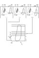
- FIG. 1 is a perspective view showing an example of the configuration inside a toilet room according to the embodiment.
- FIG. 2 is a diagram illustrating a configuration example of an information processing system according to the embodiment;
- FIG. 3 is a block diagram showing an example of the functional configuration of the toilet seat device according to the embodiment;
- FIG. 4 is a perspective view showing an example of the configuration of the toilet seat device according to the embodiment.
- FIG. 5 is a perspective view of a part of the configuration of the toilet seat device according to the embodiment.
- FIG. 6 is a front view showing part of the configuration of the toilet seat device according to the embodiment.
- FIG. 7 is a block diagram illustrating an example of the configuration of the information processing apparatus according to the embodiment;
- FIG. 8 is a diagram showing an example of a data acquisition method.
- FIG. 9 is a diagram showing an example of acquisition of data according to the dropping speed of stool.
- FIG. 10 is a diagram showing an example of acquisition of data according to the dropping speed of stool.
- FIG. 11 is a diagram showing an example of a stool image of loose stool.
- FIG. 12 is a diagram showing an example of a stool image of hard stool.
- FIG. 13 is a diagram showing an example of information used to determine the amount of feces.
- FIG. 14 is a diagram showing an example of the relationship between stool properties and stool volume.
- FIG. 15 is a diagram for explaining an example of determining the amount of stool in the case of hard stool.
- FIG. 16 is a diagram for explaining an example of determining the amount of stool in the case of hard stool.
- FIG. 15 is a diagram for explaining an example of determining the amount of stool in the case of hard stool.
- FIG. 17 is a diagram for explaining an example of determining the amount of stool in the case of loose stool.
- FIG. 18 is a diagram showing an example of correcting the length of stool.
- FIG. 19 is a diagram showing an example of correcting the length of stool.
- FIG. 20 is a diagram showing an example of a stool image including stools with different properties.
- FIG. 21 is a diagram for explaining an example of determining the amount of stool in the case of a plurality of stool properties.
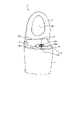
- FIG. 1 is a perspective view showing an example of the configuration inside a toilet room according to the embodiment.
- FIG. 2 is a diagram illustrating a configuration example of an information processing system according to the embodiment;
- a Western-style toilet bowl (hereinafter referred to as "toilet bowl") 7 is installed on the floor surface F. As shown in FIG. In addition, below, the direction which faces the space of the toilet room R from the floor surface F is described as the top.
- the toilet seat device 2 is provided above the toilet bowl 7 .
- the toilet bowl 7 is, for example, made of ceramic.
- a bowl portion 8 is formed in the toilet bowl 7 .
- the bowl portion 8 has a downwardly recessed shape and is a portion that receives the excrement of the user.
- the toilet bowl 7 is not limited to the floor-mounted type as shown in the drawing, and may be of any type, such as a wall-mounted type, as long as the information processing system 1 is applicable.
- the toilet bowl 7 is provided with a rim portion 9 over the entire circumference of the end of the opening facing the bowl portion 8 .
- a flush water tank that stores flush water may be installed near the toilet 7, or a so-called tankless type in which a flush water tank is not installed may be used.
- the toilet bowl is cleaned by supplying cleaning water to the bowl portion 8 of the toilet bowl 7 .
- the cleaning operation part may be an operation lever or a touch operation on the toilet bowl cleaning object displayed on the operation device 10 .
- the flushing operation unit is not limited to the operation lever or the like that allows the user to manually flush the toilet bowl. good.
- the toilet seat device 2 is attached to the upper portion of the toilet bowl 7 and includes a body portion 3, a toilet lid 4, a toilet seat 5, and a washing nozzle 6.
- the toilet seat device 2 is placed on top of a toilet bowl 7 having a bowl portion 8 for receiving excrement.
- the toilet seat device 2 is placed on the upper portion of the toilet bowl 7 so that the washing nozzle 6 advances into the bowl portion 8 before spraying washing water.
- the toilet seat device 2 may be detachably attached to the toilet bowl 7 or may be attached so as to be integrated with the toilet bowl 7 .
- the toilet seat 5 is formed in an annular shape with an opening 50 in the center, and is arranged along the rim portion 9 at a position overlapping the opening of the toilet bowl 7 .
- a user sits on the toilet seat 5 .
- the toilet seat 5 functions as a seat that supports the buttocks of a seated user.
- one end of each of the toilet lid 4 and the toilet seat 5 is pivotally supported by the main body 3, and attached so as to be rotatable (openable and closable) about the pivotal support of the main body 3. .
- the toilet lid 4 may be attached to the toilet seat device 2 as necessary, and the toilet seat device 2 may not have the toilet lid 4 .
- the washing nozzle 6 is a nozzle for spraying water for washing.
- the washing nozzle 6 can jet washing water.
- the washing nozzle 6 can jet washing water toward the user.
- the washing nozzle 6 is a nozzle for washing private parts.
- the cleaning nozzle 6 is configured to be movable forward and backward with respect to a main body cover 30 that is a housing of the main body 3 by being driven by a drive source such as an electric motor (nozzle motor 61 in FIG. 3, etc.). Also, the washing nozzle 6 is connected to a water source such as a water pipe (not shown). As shown in FIG.
- the washing nozzle 6 is at a position (hereinafter also referred to as "advancing position") with respect to the main body cover 30, which is the housing of the main body 3, and removes water from the water source. It is sprayed onto the user's body to wash the private parts.
- the operation device 10 is provided inside the toilet room R.
- the operating device 10 is provided at a position where it can be operated by the user.
- the operating device 10 is provided at an operable position when the user is seated on the toilet seat 5 .
- the operating device 10 is arranged on the wall surface W on the right side as seen from the user sitting on the toilet seat 5 .
- the operating device 10 may be arranged in various ways other than on the wall surface as long as the user sitting on the toilet seat 5 can use the operating device 10 .
- the operating device 10 may be provided integrally with the toilet seat device 2 .
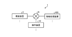
- the information processing system 1 includes a toilet seat device 2 , an operating device 10 and an information processing device 400 .
- the information processing system 1 may include a plurality of information processing devices 400 , a plurality of toilet seat devices 2 , and a plurality of operation devices 10 .
- the toilet seat device 2 is a device arranged in the toilet room R.
- the toilet seat device 2 transmits the acquired stool image to the information processing device 400 . Details such as the configuration of the toilet seat device 2 will be described later.
- the operation device 10 is communicably connected to the toilet seat device 2 and the information processing device 400 via a predetermined network (network N) by wire or wirelessly.
- a predetermined network such as network N
- the toilet seat device 2 and the operation device 10 may be connected in any way as long as information can be transmitted and received. may
- the operation device 10 receives various operations from the user via a display surface (for example, the display screen 11) by, for example, a touch panel function. Further, the operation device 10 may include switches and buttons, and receive various operations through the switches, buttons, and the like.
- the display screen 11 is, for example, a display screen of a tablet terminal realized by a liquid crystal display, an organic EL (Electro-Luminescence) display, or the like, and is a display device for displaying various information. That is, the operating device 10 accepts input from the user through the display screen 11 and also outputs to the user.
- the display screen 11 is a display device that displays various information.
- the operating device 10 accepts a user's operation to stop the control being executed by the toilet seat device 2 .
- the operating device 10 receives a user's operation for starting the execution of washing the private parts by the toilet seat device 2 .
- the operating device 10 receives instructions to the cleaning nozzle 6 from the user.
- the operation device 10 receives a user's operation for causing the toilet seat device 2 to output a predetermined sound.
- the operation device 10 receives a user's operation for performing a sterilization process of sterilizing the washing nozzle 6 (see FIG. 1) of the toilet seat device 2 with sterilized water.
- the operation device 10 receives a user's operation for adjusting the momentum of the water spouted by the toilet seat device 2 when washing the private parts.
- the operating device 10 receives a user's operation for adjusting the volume of the sound output by the toilet seat device 2 .
- the operating device 10 accepts a user's operation for selecting a language for displaying information regarding the use of the restroom on the operating device 10 or outputting the information by voice.
- the operation device 10 may display the above-described object for receiving the user's operation on the display screen 11, and execute various processes according to the user's contact with the displayed object.
- the operating device 10 may have switches, buttons, and the like for receiving the user's operations described above, and may execute various processes according to the user's contact with the switches, buttons, and the like. Note that the above is just an example, and the operation device 10 may receive an operation by a user who executes various processes.
- the information processing device 400 may be integrated with the toilet seat device 2 .
- the toilet seat device 2 functions as an information processing device that performs determination processing.
- the control unit 34 (FIG. 3) of the toilet seat device 2 may perform the determination process.
- the information processing device 400 may be integrated with a relay device (gateway) of a predetermined network (for example, network N).
- the repeater functions as an information processing device that performs determination processing. That is, the information processing device that performs the determination process may be any device included in the information processing system 1 .
- the above system configuration is merely an example, and the information processing system 1 may have any system configuration as long as it is possible to determine the amount of stools.
- the information processing system 1 detects whether the user's excrement (stool) has one of two or more types of properties based on hardness as the property of the stool, by various configurations and processes described later.
- the following example shows the case of detecting (determining) whether stool is soft or hard as an example of two or more properties based on hardness, but the properties based on hardness are limited to two types. However, the number of types may be three or more.
- the two or more properties based on hardness may be three properties of soft stool, normal stool, and hard stool.
- the information processing system 1 may detect the shape, size, quality, color, etc. of the user's excrement (stool) as the stool properties, in addition to the hardness of the stool.
- the information processing system 1 detects the user's defecation by an optical method. That is, the information processing system 1 is an information processing system capable of detecting information on excrement (stool) by optical means.
- the information processing system 1 may provide information to a user's terminal device such as a smart phone based on the measurement result.
- FIG. 3 is a block diagram showing an example of the functional configuration of the toilet seat device according to the embodiment;
- the toilet seat device 2 includes a human body detection sensor 32, a seating detection sensor 33, a control section 34, a communication section 35, an electromagnetic valve 71, a nozzle motor 61, a washing nozzle 6, an optical a unit 100; 3, illustration of a part of the configuration of the toilet seat device 2 described in FIG. 1 (main body 3, toilet seat 5, toilet bowl 7, etc.) is omitted.
- the human body detection sensor 32, the seating detection sensor 33, and the control section 34 are provided in the main body section 3 of the toilet seat device 2.
- the main unit 3 may have a storage unit outside the control unit 34 .
- the toilet seat device 2 may transmit data from the control section 34 to the storage section and store the data in the storage section.
- the human body detection sensor 32 has a function of detecting a human body.
- the human body detection sensor 32 is realized by a pyroelectric sensor or the like using an infrared signal.
- the human body detection sensor 32 may be realized by a ⁇ (micro) wave sensor or the like.
- the above is an example, and the human body detection sensor 32 may detect a human body by various means without being limited to the above.
- the human body detection sensor 32 detects a person (such as a user) who has entered the toilet room R (see FIG. 1).
- the human body detection sensor 32 outputs a detection signal to the controller 34 .
- the seating detection sensor 33 has a function of detecting a person sitting on the toilet seat device 2 .
- a seating detection sensor 33 detects that the user has sat down on the toilet seat 5 .
- the seating detection sensor 33 can detect that the user is seated on the toilet seat 5 .
- the seat detection sensor 33 also functions as a seat separation detection sensor that detects that the user leaves the toilet seat 5 .
- a seating detection sensor 33 detects the seating state of the user on the toilet seat 5 .
- the communication unit 35 is realized by a communication device, a communication circuit, etc., and communicates with the information processing device 400, the operation device 10, and the like.
- the communication unit 35 is connected to a predetermined network (network N) such as the Internet by wire or wirelessly, and transmits and receives information to and from the information processing device 400, the operation device 10, and the like.
- the communication unit 35 communicates with the information processing device 400 under the control of the control unit 34 .
- the communication unit 35 transmits the stool image acquired by the detection by the optical unit 100 to the information processing device 400 .
- the communication unit 35 transmits the stool image generated by the control unit 34 to the information processing device 400 .
- the communication unit 35 receives operation information indicating user's operation from the operation device 10 .
- the control unit 34 may be, for example, a control device that controls various configurations and processes.
- the control section 34 controls the nozzle motor 61 , the solenoid valve 71 and the optical unit 100 .
- the control unit 34 controls the nozzle motor 61 , the solenoid valve 71 and the optical unit 100 based on signals transmitted from the operating device 10 .
- the control unit 34 controls the nozzle motor 61 based on the signal of the control instruction related to washing the private parts transmitted from the operating device 10 .
- the controller 34 controls the nozzle motor 61 to move the cleaning nozzle 6 forward and backward.
- the control unit 34 controls opening and closing of the solenoid valve 71 .
- the control unit 34 transmits control information for controlling lighting and extinguishing of the light emitting unit 120 to the optical unit 100 .
- the control unit 34 transmits control information for controlling the electronic shutter function of the light receiving unit 130 to the optical unit 100 .
- the electronic shutter of the light receiving unit 130 is a shutter system that electronically controls the light receiving element 132 (imaging element) to read exposure, unlike a mechanical shutter such as a so-called lens shutter. That is, the electronic shutter of the light receiving section 130 is a so-called electronic shutter or electronically controlled shutter.
- the control unit 34 transmits control information to the nozzle motor 61, the electromagnetic valve 71, and the optical unit 100 by wire. Note that the control unit 34 may transmit control information to the nozzle motor 61, the electromagnetic valve 71, and the optical unit 100 wirelessly.
- the control unit 34 causes the optical unit 100 to emit light and receive light.
- the control section 34 controls the optical unit 100 to cause the light emitting section 120 to emit light and the light receiving section 130 to receive light.
- the control unit 34 causes the optical unit 100 to emit and receive light while the seating detection sensor 33 detects that the user is seated on the toilet seat 5 .
- the control unit 34 controls light irradiation by the light emitting unit 120 .
- the control unit 34 controls energization to the light emitting element 121 and application of voltage to the light receiving element 132 .
- the control unit 34 sends a control instruction to open the electronic shutter to the light receiving element 132, and energizes the light emitting element 121, thereby performing light receiving control so that reflected light from stool can be received.
- the control unit 34 sets the interval from the start of execution of one light reception control to the execution of the next light reception control of one light reception control to an arbitrary time (for example, 0.2 milliseconds or more) within a range in which control processing is possible. etc.).
- control mode by the control section 34 may be any mode as long as the optical unit 100 can emit and receive light as desired.
- the control mode by the control section 34 may be any mode as long as the optical unit 100 can emit and receive light as desired.
- the light emitted from the light emitting unit 120 is in one wavelength band, the light emitted from the light emitting unit 120 does not have to blink in accordance with the light receiving control, and may be emitted continuously.
- the light may be emitted continuously.
- the control unit 34 also controls the toilet lid 4 and the toilet seat 5 as shown in FIG.
- the control unit 34 controls the toilet lid 4 and the toilet seat 5 based on signals transmitted from the operating device 10 .
- the control unit 34 controls the toilet lid 4 based on the control instruction signal regarding the opening and closing of the toilet lid transmitted from the operating device 10 .
- the control unit 34 controls the toilet seat 5 based on the control instruction signal regarding the opening and closing of the seating section transmitted from the operation device 10 .
- the control unit 34 transmits control information to the toilet lid 4 and the toilet seat 5 by wire. Note that the control unit 34 may wirelessly transmit the control information to the toilet lid 4 and the toilet seat 5 .
- the control unit 34 determines whether or not the human body detection sensor 32 has detected that the user has entered the room. The control unit 34 determines whether or not the human body detection sensor 32 has detected that the user has entered the toilet room R. The control unit 34 determines whether or not the seating detection sensor 33 has detected that the user is seated. The control unit 34 determines whether or not the seating detection sensor 33 has detected that the user is seated on the toilet seat 5 .
- the control unit 34 has various configurations such as a calculation unit and a storage unit that perform calculations related to the control described above. For example, the control unit 34 uses processors such as CPU (Central Processing Unit), MPU (Micro Processing Unit), ASIC (Application Specific Integrated Circuit), etc., and integrated circuits such as FPGA (Field Programmable Gate Array). Realized.
- the control unit 34 has an ADConverter, an arithmetic processing unit, a ROM (Read Only Memory), and a first memory.
- the ADConverter is a so-called A/D converter (analog-digital conversion circuit), and has an A/D conversion function that converts analog signals into digital signals.
- the ADConverter may be an analog-to-digital conversion circuit.
- the ADConverter converts analog data received (detected) by the light receiving unit 130 into digital data.
- the ADConverter may convert analog data obtained by deleting data within a predetermined range from the analog data into digital data.
- the ADConverter may leave only data corresponding to pixels in a preset range (eg, a predetermined range in the center) and delete data corresponding to pixels in the remaining range.
- the ADConverter converts the entire analog data into digital data without deleting data in a predetermined range. Convert to data.
- the arithmetic processing unit is realized by various means such as a CPU and a microcomputer, and executes various processes. For example, the arithmetic processing unit executes various processes using digital data converted by the ADConverter.
- the arithmetic processing unit executes various processes according to programs stored in the ROM (for example, various programs related to detection processing such as a stool detection program and a stool quality determination program).
- programs stored in the ROM for example, various programs related to detection processing such as a stool detection program and a stool quality determination program.
- an arithmetic processing unit is realized by executing a program stored in a ROM using a temporarily used storage area or the like in the arithmetic processing unit as a work area.
- the processing unit analyzes the data.
- the arithmetic processing unit analyzes data temporarily stored in the first memory.
- the arithmetic processing unit transfers the data received by the light receiving unit 130 to the first memory, and analyzes and deletes the data stored in the first memory.
- the ROM stores various programs related to flight detection processing, such as a flight detection program.
- the first memory is an internal memory (storage device) that temporarily stores various data.
- the first memory stores data received by the light receiving section 130 .
- the first memory stores digital data converted by the ADConverter.
- the first memory is SRAM (Static Random Access Memory). It should be noted that the first memory is not limited to SRAM, and other RAMs (Random Access Memory) such as DRAM (Dynamic Random Access Memory) and ROMs capable of high-speed processing such as PROM (Programmable Read Only Memory) are used.
- the first memory stores data under the control of the arithmetic processing unit.
- the first memory uses a storage device with a storage capacity of 96 kilobytes, 512 kilobytes, or the like.
- the data received by the light receiving unit 130 temporarily stored in the first memory includes raw data (analog data) detected by the light receiving unit 130 and data processed by A/D conversion (digital data). data).
- the second memory is an external memory (storage device) that stores various data.
- the second memory stores digital data acquired from the control unit 34 .
- an EEPROM Electrically Erasable Programmable Read-Only Memory
- the second memory may be SD (Secure Digital) card memory, USB (Universal Serial Bus) memory, or any other storage device (memory).
- the second memory can transfer data stored in the first memory.
- the second memory has a larger storage area than the first memory.
- the second memory uses a storage device with a larger storage capacity than the first memory, such as 4 gigabytes.
- Data stored in the second memory may be transmitted to an external device.
- the information processing system 1 may wirelessly transmit the data stored in the second memory to an external device such as a terminal device used by the user, using a communication device or the like of the toilet seat device 2 .
- the second memory may be provided inside the toilet seat device 2, outside the toilet seat device 2, or the like.
- the second memory may be a MicroSD inside the toilet seat device 2, or an external memory located outside the toilet seat device 2 and communicating with the toilet seat device 2 via Wi-Fi (registered trademark) (Wireless Fidelity) or the like. There may be.
- the processing unit transfers the data temporarily stored in the first memory to the second memory by communicating with the second memory, which is an external memory having a larger storage area than the first memory. transfer to The communication between the second memory and the toilet seat device 2 is not limited to Wi-Fi (registered trademark), and may be communication using various communication standards such as ZigBee (registered trademark) or Bluetooth (registered trademark). good.
- control unit 34 generates a stool image based on information detected by the optical unit 100 .
- the control unit 34 stores one-dimensional data (linear still images) obtained over time at predetermined time intervals by the light receiving element 132, which is a line sensor in which a plurality of elements are linearly arranged. , to generate one two-dimensional image.
- the control unit 34 generates a two-dimensional image of stool based on the one-dimensional image detected by the optical unit 100, which will be explained with reference to FIG.
- the solenoid valve 71 has the function of a valve that electromagnetically controls the flow of fluid.
- the electromagnetic valve 71 switches between supply and stop of tap water from a water supply pipe, for example.
- the solenoid valve 71 performs opening/closing control according to instructions from the control unit 34 .
- the nozzle motor 61 is a drive source (motor) that drives the cleaning nozzle 6 to move forward and backward.
- the nozzle motor 61 performs control to move the cleaning nozzle 6 forward and backward with respect to the body cover 30 of the body portion 3 .
- the nozzle motor 61 performs control to move the cleaning nozzle 6 forward and backward according to instructions from the control unit 34 .
- the optical unit 100 includes a light emitting section 120 and a light receiving section 130 .
- the optical unit 100 functions as a detection section (detection device) having a light receiving element 132 in which a plurality of elements are linearly arranged to detect falling stool.
- the light emitting unit 120 emits light.
- the light emitting unit 120 has a light emitting element 121 that emits light.
- the light emitting unit 120 emits light to the excrement excreted by the user.
- the light emitting unit 120 irradiates light to stool excreted by the user.
- the light emitting unit 120 irradiates the falling stool with light.
- the light emitting unit 120 is provided with a light emitting element 121 that emits light.
- the light emitting unit 120 is provided with a light emitting element 121 that emits light forward.
- the light emitting unit 120 is provided with a light emitting element 121 that emits light forward toward excrement excreted by the user.
- the light emitting element 121 is an LED (Light Emitting Diode). Note that the light-emitting element 121 is not limited to an LED, and various elements may be used.
- the light emitting unit 120 emits light forward.
- the light emitting unit 120 emits light forward toward the stool excreted by the user.
- the light emitting section 120 includes a plurality of light emitting elements 121 .
- the light emitting unit 120 includes a plurality of light emitting elements 121 that emit light.
- the light emitting unit 120 irradiates light onto falling stool excreted by the user.
- the light emitting unit 120 includes a plurality of light emitting elements 121 for emitting light with different wavelengths. It should be noted that the above is merely an example, and as for the light-emitting elements 121 of the light-emitting section 120, any configuration can be adopted as long as desired light emission is possible with respect to the number and light emission wavelength.
- the light receiving unit 130 receives light.
- the light receiving section 130 has a lens 131 and a light receiving element 132 that receives light.
- the light receiving unit 130 receives the light emitted by the light emitting unit 120 and reflected from the excrement.
- the light receiving unit 130 receives the reflected light from the stool with respect to the light emitted by the light emitting unit 120 .
- the light receiving unit 130 receives the reflected light from the falling stool with respect to the light emitted by the light emitting unit 120 .
- the light receiving unit 130 is provided with a light receiving element 132 that receives light.
- the light receiving section 130 has a light receiving element 132 in which a plurality of elements are linearly arranged to detect falling stool.
- the light receiving element 132 is a line sensor.
- the light receiving element 132 is a line sensor in which CCD (Charge Coupled Device) sensors or CMOS (Complementary Metal Oxide Semiconductor) sensors are arranged in a line.
- CCD Charge Coupled Device
- CMOS Complementary Metal Oxide Semiconductor
- the light receiving element 132 is not limited to a one-dimensional line sensor (one-dimensional image sensor), and various sensors such as a line sensor in which lines are arranged in two or more rows and an area sensor (two-dimensional image sensor) are used. may be
- the light receiving section 130 includes a lens 131 for condensing light in front of the light receiving element 132 .
- a case is provided around the light receiving element 132 as a cover for suppressing incidence of light from other than the front of the light receiving element 132 .
- a case, which is a cover, is provided around the light receiving element 132 to prevent light other than the light passing through the lens 131 arranged in front from entering the light receiving element 132 .
- a case is provided around the light receiving element 132 as a cover for suppressing incidence of light from the lateral direction of the light receiving element 132 .
- the case functions as an incident suppression cover that blocks or attenuates light from other than the front of the light receiving element 132 .
- the case is colored in a color such as black that does not easily reflect light, thereby suppressing light reflected from the case itself from entering the light receiving element.
- Various materials such as resin may be used for the case as long as it can be formed into a desired shape.
- the light receiving unit 130 receives the reflected light from the stool with respect to the light emitted by the light emitting unit 120 .
- the light receiving unit 130 receives the reflected light from the falling stool with respect to the light emitted by the light emitting unit 120 .
- the light receiving unit 130 receives the reflected light from the stool with respect to the light emitted by the light emitting unit 120 .
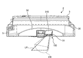
- FIG. 4 is a perspective view showing an example of the configuration of the toilet seat device according to the embodiment.
- FIG. 4 is a diagram showing a state in which the toilet seat 5 is raised with the shielding part 310 removed.
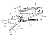
- FIG. 5 is a perspective view of a part of the configuration of the toilet seat device according to the embodiment.
- FIG. 6 is a front view showing part of the configuration of the toilet seat device according to the embodiment.
- FIG. 6 is a front cross-sectional view taken along a plane that passes through the opening 50 of the toilet seat 5 and is perpendicular to the front-rear direction.
- FIG. 5 and 6 show an overview of the shielding of light directed toward the opening 50 of the toilet seat 5 by the shielding portion 310.
- FIG. An assumed buttock position EG in FIG. 5 virtually shows an example of the assumed position of the user's buttocks when the user is seated on the toilet seat 5 .
- the light emitting part 120 and the light receiving part 130 of the optical unit 100 are exposed through the opening 31 of the body cover 30 .
- the light emitting unit 120 can irradiate the excrement in the toilet 7 with light, and the light receiving unit 130 can receive reflected light from the excrement in the toilet 7 .
- FIG. 4 also shows a state where the cleaning nozzle 6 (see FIG. 1) is in a position (hereinafter also referred to as "storage position") in which it is housed inside the main body cover 30.
- a position hereinafter also referred to as "storage position”
- FIG. 4 when the cleaning nozzle 6 is in the retracted position, the nozzle cover 60 is closed and the cleaning nozzle 6 is hidden behind the nozzle cover 60 .
- the nozzle cover 60 is opened, and the cleaning nozzle 6 protrudes from the opening of the main body cover 30 (opening closed by the nozzle cover 60 in the closed state in FIG. 4). transitions to the advance state.
- the shielding part 310 is arranged along the upper end of the opening 31 of the main body cover 30 so as to shield the light from the light emitting part 120 toward the opening 50 of the toilet seat 5 .
- the shielding part 310 is formed of a material with no (low) permeability.
- the shielding part 310 is made of the same material as the body cover 30 .
- the irradiation area ER indicates the area irradiated with light from the light emitting unit 120 (light emitting element 121).
- a light receiving region LR indicates a region where the light receiving element 132 receives light.
- the shielding part 310 is arranged above the light emitting part 120 at a position such that the range of the opening 50 of the toilet seat 5 is not included in the irradiation area ER. Thereby, the toilet seat device 2 can suppress the irradiation of light from the light emitting portion 120 to the opening 50 of the toilet seat 5 .
- FIG. 7 is a block diagram illustrating an example of the configuration of the information processing apparatus according to the embodiment; Specifically, FIG. 7 is a block diagram showing an example of the configuration of an information processing device 400, which is an example of an information processing device.
- the information processing device 400 has a communication unit 410, a storage unit 420, and a control unit 430.
- the information processing apparatus 400 includes an input unit (for example, a keyboard, a mouse, etc.) that receives various operations from the administrator of the information processing apparatus 400, and a display unit (for example, a liquid crystal display, etc.) for displaying various information. may have.
- the communication unit 410 is realized by, for example, a communication circuit or the like.
- the communication unit 410 is connected to the network N (see FIG. 2) by wire or wirelessly, and transmits and receives information to and from an external information processing device.
- the communication unit 410 is connected to the network N (see FIG. 2) by wire or wirelessly, and transmits and receives information to and from the toilet seat device 2, the operation device 10, and the like.
- the storage unit 420 is implemented, for example, by a semiconductor memory device such as a RAM or flash memory, or a storage device such as a hard disk or optical disk.
- the storage unit 420 is a computer-readable recording medium that non-temporarily records data used by an amount determination program for determining the amount of stool and a property determination program for determining the property of stool.
- storage part 420 which concerns on embodiment has the flight information memory
- the flight information storage unit 421 stores various information used for determination processing.
- the flight information storage unit 421 stores a threshold used for determination processing.
- the flight information storage unit 421 stores a function for deriving the volume of flights.
- the stool information storage unit 421 stores information about the detected stool (excretion).
- the stool information storage unit 421 stores stool images.
- the flight information storage unit 421 stores information about flights corresponding to flight images in association with the flight images.
- the flight information storage unit 421 stores the determination result of the flight corresponding to the flight image in association with the flight image.
- the stool information storage unit 421 stores information such as the properties of stool corresponding to the stool image and the amount of stool corresponding to the stool image. Further, the stool information storage unit 421 may store the date and time when the stool image was acquired, information identifying the user who excreted the stool corresponding to the stool image, etc., in association with the stool image. Note that the above is only an example, and the flight information storage unit 421 stores various information regarding flights.
- the control unit 430 uses, for example, a CPU, a GPU (Graphics Processing Unit), etc., to store programs stored inside the information processing device 400 (for example, the amount determination program, the property determination program, etc. according to the present disclosure), and the like, to the RAM or the like as a work area. It is realized by executing as Also, the control unit 430 is implemented by an integrated circuit such as an ASIC or FPGA, for example.
- control unit 430 has an acquisition unit 431, a determination unit 432, and a provision unit 433, and implements or executes the information processing functions and actions described below.
- the internal configuration of the control unit 430 is not limited to the configuration shown in FIG. 7, and may be another configuration as long as it performs information processing to be described later.
- the acquisition unit 431 acquires information.
- Acquisition unit 431 functions as a stool image acquisition unit that acquires a stool image.
- Acquisition unit 431 acquires various types of information from storage unit 420 .
- the acquisition unit 431 receives various information from the toilet seat device 2 and the operation device 10 .
- the acquisition unit 431 receives information about stool from the toilet seat device 2 .
- the acquisition unit 431 receives a stool image (data) from the toilet seat device 2 .
- the acquisition unit 431 is provided in the toilet seat device 2 placed on the upper part of the toilet bowl 5 in which the bowl portion 8 for receiving excrement is formed.
- a feces image based on information from the optical unit 100 having the light receiving element 132 is acquired.
- the acquisition unit 431 stores the acquired flight image in the flight information storage unit 421 .
- the determination unit 432 performs various determination processes.
- the determination unit 432 uses the information acquired from the toilet seat device 2 to perform determination processing.
- the determination unit 432 performs determination processing using information stored in the storage unit 420 .
- the determination unit 432 determines the properties of the stool corresponding to the stool image based on the stool image.
- the determining unit 432 determines the properties of the stool corresponding to the stool image.
- the determining unit 432 determines whether the hardness of the stool corresponding to the stool image is one of two or more properties based on hardness. For example, using the stool image, the determination unit 432 determines whether the hardness of the stool corresponding to the stool image is either soft stool or hard stool.
- the judgment unit 432 judges the properties of stool from the detection result by the toilet seat device 2 .
- the determination unit 432 determines the properties of the user's stool by appropriately using various techniques for detecting the properties of stool by an optical technique.
- the determination unit 432 determines whether the hardness of the stool is either soft stool or hard stool by appropriately using various techniques related to classification of stool properties. For example, the determination unit 432 determines (determines) the properties of stool based on various information (feature amounts) such as the length of the stool image in the falling direction and the number of stools (lumps).
- the determination unit 432 determines that the property (hardness) of the stool corresponding to the stool image is loose stool. For example, when there are a plurality of lumps whose length is less than a predetermined value in the stool image, the determination unit 432 determines that the property of the plurality of lumps (stool) is loose stool. For example, in a stool image, when lumps having a length less than a predetermined value are continuous, the determining unit 432 determines that the continuous lumps (stool) are loose stools.
- the determining unit 432 determines that the property of that one stool (lump) is hard stool. For example, when there is a mass with a length equal to or greater than a predetermined value in the stool image, the determination unit 432 determines that the property of the mass (stool) is loose stool.
- the determination unit 432 may use various information as appropriate to determine the nature of stool.
- the determination unit 432 may determine the properties of stool using a technology related to AI (artificial intelligence).
- AI artificial intelligence
- the determination unit 432 may determine the properties of stool using a learning model (property determination model) generated by machine learning.
- the property determination model is learned in advance using teacher data indicating classification determination.
- This training data includes a plurality of combinations of stool images and labels (correct information) indicating properties (soft stools or hard stools) of lumps (stools) included in the stool images.
- the property determination model is a model that receives a stool image as input and outputs information indicating the property of each lump (stool) included in the input stool image.
- the property determination model is learned to output label (property of each mass) information corresponding to the input stool image when the stool image is input. Learning of the property determination model is performed by using various techniques related to so-called supervised learning as appropriate.
- the property determination model may be stored in the storage unit 420, and the determination unit 432 may use the property determination model stored in the storage unit 420 to determine the property of stool.
- the information processing apparatus 400 may perform learning processing to generate a property determination model.
- the determination unit 432 when acquiring information about the properties of stool from another device, the determination unit 432 does not need to determine the properties of stool. For example, when the toilet seat device 2 determines the properties of the stool and acquires information on the properties of the stool from the toilet seat device 2, the determination unit 432 does not need to determine the properties of the stool.
- an input means is provided to the information processing device 400, and information on the properties of stool determined by the user using a portable information terminal or the like is acquired, and the information is processed. It may be input to device 400 .
- the determination unit 432 determines the amount of feces.
- the determination unit 432 determines at which level the stool volume is in a plurality of stages (levels). For example, the determination unit 432 determines which amount (level) the amount of stool is among three levels (levels) of "small”, “normal”, and “large”. It should be noted that the three levels (levels) of "small”, “normal”, and “large” are merely examples, and the determination unit 432 determines which amount (level) among the four or more levels (levels). It may be determined whether For example, the determination unit 432 determines which amount (step) of the five levels (levels) of "low”, “slightly low”, “normal”, “slightly high”, and “high”. You can judge.
- a numerical value that serves as a guideline for the weight or volume of stool such as 100 g or 100 mL, may be used for determination.
- the determination unit 432 determines the amount of stool from the stool image.
- the determination unit 432 determines the amount of stool based on the relationship between the amount of stool and the length of the stool falling direction in the stool image, and the properties of the stool determined from the stool image.
- the determination unit 432 determines the amount of stool based on the relationship between the amount of stool and the area calculated from the width and length of the stool in the direction intersecting the dropping direction of the stool image, and the properties of the stool. For example, the determination unit 432 determines the amount of stool when the length or area of stool and the nature of stool are known by using the relational expression between the amount of stool and the length or area generated for each shape of stool.
- the relational expression here is a function that inputs, for example, the length or area of stool and outputs a value indicating the corresponding amount of stool.
- the determining unit 432 selects the relational expression corresponding to the stool properties from among the relational expressions corresponding to each stool shape, and uses the relational expression and the length or area of the stool to determine the amount of stool. You can (specify).
- the determination unit 432 corrects the total length, and determines the amount of stools based on the corrected total length. judge. Details of determination of the amount of stool by the determination unit 432 will be described later.
- the providing unit 433 provides information.
- the providing unit 433 transmits information to an external information processing device.
- the providing unit 433 transmits various information to the portable terminal (user terminal) of the user who uses the toilet seat device 2 , the operation device 10 and the toilet seat device 2 .
- the provision unit 433 provides the information determined by the determination unit 432 to the user terminal or the like.
- the provision unit 433 transmits information on the amount of flights determined by the determination unit 432 to the user terminal or the like.
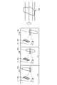
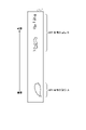
- FIG. 8 is a diagram showing an example of a data acquisition method. Description of points similar to those described above will be omitted as appropriate.
- An object OB1 schematically shows stool (excretion) to be detected (measured).
- the light receiving device PD is a light receiving section 130 having a light receiving element 132 such as a line sensor.
- the light emitting device LE is a light emitting section 120 having a light emitting element 121 .
- the case where the light emitting device LE emits light of one wavelength will be described as an example, but the light emitting device LE may emit light of different wavelengths.
- the falling object OB1 is irradiated with light from the light emitting device LE, and a process of acquiring (generating) a flight image (two-dimensional image) based on the result of light reception by the light receiving device PD is performed.
- a dotted line extending from the light emitting device LE to the object OB1 schematically shows the irradiation of light from the light emitting device LE to the object OB1
- a dotted line extending from the object OB1 to the light receiving device PD represents the object received by the light receiving device PD. Reflected light from OB1 is shown schematically.
- a rectangular frame overlapping the object OB1 schematically shows the range (one-dimensional) of the object OB1 detected by corresponding light emission and light reception.
- the light-emitting unit 120 and the light-receiving unit 130 are arranged so that the position where the object OB1 is irradiated with light and reflected is located approximately 80 mm downward from the upper surface (rim portion 9) of the toilet bowl 7 in FIG. placed.
- the position where the object OB1 is irradiated with light and reflected is assumed to be a position around 80 mm below the upper surface (rim portion 9) of the toilet bowl 7 in FIG. Any position may be used as long as irradiation and reflection are performed, and may be changed as appropriate.
- the scene SN1 conceptually shows the process of irradiating the falling object OB1 with light from the light emitting device LE and receiving light by the light receiving device PD at time t1.
- Data acquired in scene SN1 corresponds to one-dimensional image PI1 of two-dimensional image EI. That is, the toilet seat device 2 acquires (detects) the one-dimensional image PI1 by light emission and light reception in scene SN1 (time t 1 ).
- the data acquired at time t2 corresponds to the one-dimensional image PI2 of the two -dimensional image EI. That is, the toilet seat device 2 acquires (detects) the one-dimensional image PI2 by light emission and light reception at time t2.
- the data at time t2 is the data acquired after the data at time t1. Therefore, the toilet seat device 2 generates the two-dimensional image EI by arranging the one-dimensional image PI2 next to the one-dimensional image PI1.
- the scene SNi conceptually shows the process of irradiating the falling object OB1 with light from the light emitting device LE and receiving light by the light receiving device PD at time t i .
- the data acquired in the scene SNi correspond to the one-dimensional image PIi of the two-dimensional image EI. That is, the toilet seat device 2 acquires (detects) the one-dimensional image PIi by light emission and light reception in the scene SNi (time t i ).
- a scene SNj conceptually shows the process of irradiating the falling object OB1 with light from the light emitting device LE and receiving light by the light receiving device PD at time tj.
- Data acquired at scene SNj corresponds to one-dimensional image PIj of two-dimensional image EI. That is, the toilet seat device 2 obtains (detects) the one-dimensional image PIj by light emission and light reception at the scene SNj (time tj ).
- the toilet seat device 2 generates a two-dimensional image (stool information) by arranging the one-dimensional images side by side in the order of the time when the one-dimensional images (received light data) were acquired. 8, the toilet seat device 2 generates a two-dimensional image EI by arranging one-dimensional images PI1, PI2, . . . , PIi, .
- the toilet seat device 2 emits the light-receiving data (one-dimensional image) obtained by causing the light-emitting element 121 (also referred to as “first light-emitting element 121”) that emits light of the first wavelength to emit light, in chronological order. By arranging them side by side, a two-dimensional image corresponding to the first light emitting element 121 is generated.
- the toilet seat device 2 arranges light reception data (one-dimensional image) obtained by emitting light of a first wavelength such as 590 nm in time series to obtain fecal information (first two-dimensional image) corresponding to the first wavelength. to generate
- the toilet seat device 2 emits the light-receiving data (one-dimensional image) obtained by causing the light-emitting element 121 (also referred to as “second light-emitting element 121”) that emits light of the second wavelength to emit light, in chronological order. By arranging them side by side, a two-dimensional image corresponding to the second light emitting element 121 is generated.
- the toilet seat device 2 arranges the received light data (one-dimensional image) obtained by emitting light of a second wavelength such as 670 nm in chronological order to obtain fecal information (second two-dimensional image) corresponding to the second wavelength. to generate
- the toilet seat device 2 emits the light-receiving data (one-dimensional image) obtained by causing the light-emitting element 121 (also referred to as “third light-emitting element 121”) that emits light of the third wavelength to emit light in the order of time. By arranging them side by side, a two-dimensional image corresponding to the third light emitting element 121 is generated.
- the toilet seat device 2 arranges the received light data (one-dimensional image) obtained by emitting light of a third wavelength such as 870 nm in time series to obtain fecal information (third two-dimensional image) corresponding to the third wavelength. to generate
- the toilet seat device 2 generates a two-dimensional image for each of three wavelengths corresponding to each of the first light emitting element 121, the second light emitting element 121 and the third light emitting element 121, thereby producing a color image.
- the toilet seat device 2 may generate a color image by synthesizing the above-described first two-dimensional image, second two-dimensional image, and third two-dimensional image.
- the light receiving element such as a line sensor of the light receiving section 130 may be a color light receiving element, the light emitting elements of a plurality of colors may be irradiated at the same time, and the color of the reflected light may be detected by the light receiving section to generate a color image. .
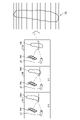
- FIG. 9 is a diagram showing an example of acquisition of data according to the dropping speed of stool. Specifically, FIG. 9 shows an example of data acquisition when the drop speed of stool is high.
- the falling speed of the object OB1 is fast, and the time for crossing the light receiving device PD and the light emitting device LE is short.
- the object OB1 passes through the light receiving device PD and the light emitting device LE faster than in the case of FIG.
- the length of the falling direction of the object OB1 crossing the light emitting device (LE) is increased.
- the object OB1 has fallen further than in FIG. That is, the position of the object OB1 indicated by the scene SNi in FIG. 9 is lower than the position of the object OB1 indicated by the scene SNi in FIG.
- the toilet seat device 2 generates a two-dimensional image EIS by arranging one-dimensional images side by side in chronological order such as time t 1 . . . and time t i .
- the two-dimensional image EIS is a feces image shorter in length than the two-dimensional image EI of FIG.
- the falling speed of the object OB1 is slow, and the time it takes to cross the light receiving device PD and the light emitting device LE is long.
- the object OB1 passes through the light receiving device PD and the light emitting device LE later than in the case of FIG.
- the length of the falling direction of the object OB1 crossing the light emitting device LE) is shortened.
- the fall of the object OB1 is later than in FIG. 8, for example, at time t i . That is, the position of the object OB1 indicated by the scene SNi in FIG. 10 is higher than the position of the object OB1 indicated by the scene SNi in FIG.
- the toilet seat device 2 generates a two-dimensional image EIL by arranging the one-dimensional images in chronological order such as time t 1 . . . and time t i .
- the two-dimensional image EIL is a feces image longer than the two-dimensional image EI of FIG.
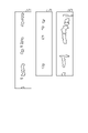
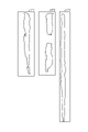
- FIG. 11 is a diagram showing an example of a stool image of loose stool.
- Three stool images LF1, LF2, and LF3 in FIG. 11 show an example of stool images when the stool property is loose stool.
- the stool when the stool is soft, the stool contains a large amount of water and is torn off (separated into a plurality of lumps) by its own weight and falls.
- FIG. 12 is a diagram showing an example of a stool image of hard stool.
- Three stool images HF1, HF2, and HF3 in FIG. 12 show an example of stool images when the stool property is hard stool.
- the stool image HF3 shows a case where the stool is imaged as stool that is attached to the body and slowly dropped (moved).
- the stool becomes a large lump to some extent.
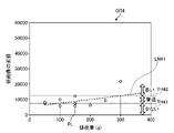
- FIG. 13 is a diagram showing an example of information used to determine the amount of feces.
- the information processing device 400 uses the first parameter PM1 indicating the length of the dropping direction (longitudinal direction) of the feces as the information used to determine the amount of feces.
- the information processing apparatus 400 uses the second parameter PM2 indicating the width of the stool in the horizontal direction (width direction) as information used for determining the amount of stool.
- the information processing device 400 may use the average (value) over the length direction for the second parameter PM2 indicating the width of the stool.
- the information processing device 400 derives the area of the stool by using the average (value) of the width of the stool over the length direction as the second parameter PM2. Also, for example, the area is obtained by dividing the dropping direction (longitudinal direction) of the stool into predetermined intervals (for example, 10 pixels), calculating the average value of the width of the stool at the predetermined interval, and multiplying it by the length of the predetermined interval ( area at predetermined intervals) may be integrated and derived.
- predetermined intervals for example, 10 pixels
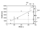
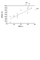
- FIG. 14 is a diagram showing an example of the relationship between stool properties and stool volume. Specifically, FIG. 14 shows the relationship between information obtained from a stool image, stool properties, and the amount of stool (amount of stool).
- the amount of defecation in FIG. 14 is the measurement result obtained from the difference in body weight of the user (subject) before and after defecation. The user (subject) did not urinate during defecation, and the accuracy of the weight scale used was ⁇ 50 g.
- the vertical axis of graph GR1 in FIG. 14 indicates the area of stools included in the stool image (area of stool image), and the horizontal axis indicates the amount of stool (amount of feces).
- Plots (data) indicated by squares ( ⁇ ) in FIG. 14 show measurement results when the stool is hard.
- a function LN11 indicated by a straight line in FIG. 14 is a function that indicates the relationship between the area of the stool image and the amount of stool when the stool is hard.
- the function LN11 is a function derived based on the plot indicated by squares ( ⁇ ) in FIG.
- the function LN11 is derived by appropriately using a technique for deriving a function corresponding to (representing) a plurality of data (for example, regression analysis such as the least squares method).
- the function LN11 may be a function that receives as an input the area of a stool image of stool with hard stool properties and outputs a value indicating the amount of stool corresponding to the stool image.
- a function LN12 indicated by a straight line in FIG. 14 is a function that indicates the relationship between the area of the stool image and the amount of stool when the stool property is soft stool.
- the function LN12 is a function derived based on the plot indicated by triangles ( ⁇ ) in FIG.
- the function LN12 is derived by appropriately using a technique (for example, regression analysis such as the least squares method) for deriving functions corresponding to (representing) a plurality of data.
- the function LN12 may be a function that inputs the area of a stool image of soft stool and outputs a value indicating the amount of stool corresponding to the stool image.
- the area of the stool image is a value based on the width of the stool, such as the length of the stool image (first parameter PM1) and the average width of the stools included in the image (flight image). It may be derived without using the image width (second parameter PM2).
- the area of the stool image may be derived by counting the number of pixels.
- the information used for deriving the amount of stool is not limited to the area of the stool image, and various information related to the stool image may be used.
- the length of the stool image may be used to determine the amount of stool based on the relationship between the length of the stool image and the amount of stool, which will be described later.
- the information processing apparatus 400 can accurately determine the amount of stool in multiple stages by setting a threshold value for the length or area (upper diagram) in the falling direction according to each property.
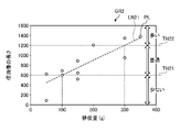
- the vertical axis of graph GR2 in FIG. 15 indicates the length of the stool image, and the horizontal axis indicates the amount of feces (amount of feces).
- Plots PL (data) indicated by circles ( ⁇ ) in FIG. 15 show measurement results when the stool is hard. In FIG. 15, only one is marked with the symbol "PL", but all the circles (o) in the graph GR2 indicate the measurement results.
- a function LN21 indicated by a straight line in FIG. 15 is a function that indicates the relationship between the length of the stool image and the amount of stool when the stool property is hard stool.
- the function LN21 is a function derived based on the plot PL (data) indicated by the circle (o) in FIG.
- the function LN21 is derived by appropriately using a technique for deriving a function corresponding to (representing) a plurality of data (for example, regression analysis such as the least squares method).
- the function LN21 may be a function that inputs the length of a stool image of hard stool and outputs a value indicating the amount of stool corresponding to the stool image.
- the information processing apparatus 400 can estimate the amount of stool corresponding to the stool image from the length of the stool image using the function LN21.
- the information processing device 400 determines the amount of stool using a plurality of thresholds.
- the information processing apparatus 400 determines the amount of stool using two thresholds, a first threshold and a second threshold that is a larger value than the first threshold.
- the information processing device 400 uses a first threshold and a second threshold to determine the amount of stool in three stages. In this case, for example, when the length of the stool image is less than the first threshold, the information processing device 400 determines that the amount of stool is “small”. Further, the information processing apparatus 400 determines the amount of stool to be "normal" when the length of the stool image is equal to or greater than the first threshold and less than the second threshold. Further, when the length of the stool image is equal to or greater than the second threshold, the information processing device 400 determines that the amount of stool is "large”.
- the amount of defecation when the amount of defecation is less than 100 g, the amount of feces is "small", when the amount of defecation is 100 g or more and less than 300 g, the amount of feces is "normal", and when the amount of defecation is 300 g or more. indicates that the amount of stool is “large”.
- the length of the stool image corresponding to the amount of stool "100 g" is set as the first threshold TH21
- the length of the stool image corresponding to the amount of stool "300 g" is set as the second threshold TH22.
- the first threshold TH21 and the second threshold TH22 are determined based on the information of the graph GR2.
- the amount of stool is set in three stages ("small”, “normal”, and “large”) here, the number may not be three, and judgment may be made by further subdividing.
- a plurality of thresholds are used to determine the amount of feces here, the value of the threshold and the number of thresholds may be changed as appropriate. Further, it is not always necessary to use a threshold, and the length of stool may be corrected by setting a coefficient or the like according to the value of the length of the stool image (length of stool).
- the first threshold TH21 is determined to be "600".
- the value "600” of the length of the stool image corresponding to the amount of stool "100 g" on the horizontal axis is set as the first threshold value TH21.
- the second threshold TH22 is determined to be "1200”.
- the value "1200" of the length of the stool image corresponding to the amount of stool "300 g" on the horizontal axis is set as the second threshold TH22.
- the first threshold TH21 and the second threshold TH22 may be set in advance, or the information processing apparatus 400 may determine the first threshold TH21 and the second threshold TH22 using the information of the graph GR2 and the function LN21. good.
- the information processing apparatus 400 determines the amount of stool using "600" as the first threshold and "1200" as the second threshold. do. For example, when the length of the acquired stool image is "500”, the information processing apparatus 400 determines that the amount of stool corresponding to the stool image is "small”. When the length of the acquired stool image is "1000”, the information processing apparatus 400 determines that the amount of stool corresponding to that stool image is "normal”. When the length of the acquired stool image is "1500", the information processing apparatus 400 determines that the amount of stool corresponding to the stool image is "large”.
- FIG. 16 is a diagram for explaining an example of determining the amount of stool in the case of hard stool. Specifically, FIG. 16 is a diagram showing an example of determining the amount of stool in the case of hard stool using the area of the stool. Note that the description of the same points as those described above will be omitted as appropriate.
- the vertical axis of graph GR3 in FIG. 16 indicates the area of the stool image, and the horizontal axis indicates the amount of defecation (amount of feces).
- Plots PL (data) indicated by circles ( ⁇ ) in FIG. 16 show measurement results when the stool is hard. In FIG. 16, only one is marked with a symbol "PL", but all circles (o) in the graph GR3 indicate the measurement results.
- a function LN31 indicated by a straight line in FIG. 16 is a function that indicates the relationship between the area of the stool image and the amount of stool when the stool property is hard stool.
- the function LN31 is a function derived based on the plot PL (data) indicated by the circle (o) in FIG.
- the function LN31 is derived by appropriately using a technique for deriving a function corresponding to (representing) a plurality of data (for example, regression analysis such as the least squares method).
- the function LN31 may be a function that receives as input the area of a stool image of stool with hard stool properties and outputs a value indicating the amount of stool corresponding to the stool image.
- the information processing apparatus 400 can estimate the amount of stool corresponding to the stool image from the area of the stool image using the function LN31.
- the information processing device 400 uses the first threshold and the second threshold to determine the amount of stool in three stages. In this case, for example, when the area of the stool image is less than the first threshold, the information processing device 400 determines that the amount of stool is “small”. Further, the information processing apparatus 400 determines the amount of feces to be "normal" when the area of the feces image is equal to or greater than the first threshold and less than the second threshold. Further, when the area of the stool image is equal to or larger than the second threshold, the information processing device 400 determines that the amount of stool is "large”.
- the amount of defecation when the amount of defecation is less than 100 g, the amount of feces is "small", when the amount of defecation is 100 g or more and less than 300 g, the amount of feces is "normal", and when the amount of defecation is 300 g or more. indicates that the amount of stool is “large”.
- the area of the stool image corresponding to the amount of stool "100 g" is set as the first threshold TH31
- the area of the stool image corresponding to the amount of stool "300 g" is set as the second threshold TH32.
- the first threshold TH31 and the second threshold TH32 are determined based on the information of the graph GR3.
- the first threshold TH31 is determined to be "16000".
- the value "16000" of the area of the stool image (area of stool) corresponding to the amount of stool "100 g" on the horizontal axis is set as the first threshold value TH31.
- the second threshold TH32 is determined to be "40000".
- the value of the area of the fecal image corresponding to the amount of feces of "300 g" on the horizontal axis is set to "40000" as the second threshold TH32.
- the first threshold TH31 and the second threshold TH32 may be set in advance, or the information processing apparatus 400 may determine the first threshold TH31 and the second threshold TH32 using the information of the graph GR3 and the function LN31. good.
- the information processing apparatus 400 determines the amount of stool using "16000" as the first threshold and "40000" as the second threshold. . For example, when the area of the acquired feces image is "10000", the information processing apparatus 400 determines that the amount of feces corresponding to the feces image is "small”. When the area of the acquired feces image is "30000”, the information processing apparatus 400 determines that the amount of feces corresponding to the feces image is "normal”. When the area of the acquired feces image is "50000", the information processing apparatus 400 determines that the amount of feces corresponding to the feces image is "large”.
- FIG. 17 is a diagram for explaining an example of determining the amount of stool in the case of loose stool. Specifically, FIG. 17 is a diagram showing an example of determining the amount of loose stool using the area of the stool. Note that the description of the same points as those described above will be omitted as appropriate.
- the vertical axis of graph GR4 in FIG. 17 indicates the area of the stool image, and the horizontal axis indicates the amount of defecation (amount of feces).
- Plots PL (data) indicated by circles ( ⁇ ) in FIG. 17 show measurement results when the stool is soft. In FIG. 17, only one is marked with a symbol "PL", but all circles (o) in the graph GR4 indicate measurement results.
- a function LN41 indicated by a straight line in FIG. 17 is a function that indicates the relationship between the area of the stool image and the amount of stool when the stool property is soft stool.
- the function LN41 is a function derived based on the plot PL (data) indicated by the circle (o) in FIG.
- the function LN41 is derived by appropriately using a technique for deriving a function corresponding to (representing) a plurality of data (for example, regression analysis such as the least squares method).
- the function LN41 may be a function that inputs the area of a stool image of loose stool and outputs a value indicating the amount of stool corresponding to the stool image.
- the information processing apparatus 400 can estimate the amount of stool corresponding to the stool image from the area of the stool image using the function LN41.
- the information processing device 400 uses the first threshold and the second threshold to determine the amount of stool in three stages. In this case, for example, when the area of the stool image is less than the first threshold, the information processing device 400 determines that the amount of stool is “small”. Further, the information processing apparatus 400 determines the amount of feces to be "normal" when the area of the feces image is equal to or greater than the first threshold and less than the second threshold. Further, when the area of the stool image is equal to or larger than the second threshold, the information processing device 400 determines that the amount of stool is "large”.
- the amount of stool when the amount of stool is less than 100 g, the amount of stool is "small”, when the amount of stool is 100 g or more and less than 300 g, the amount of stool is "normal”, and when the amount of stool is 300 g or more. indicates that the amount of stool is “large”.
- the area of the stool image corresponding to the amount of stool "100 g" is set as the first threshold TH41, and the area of the stool image corresponding to the amount of stool "300 g" is set as the second threshold TH42.
- the first threshold TH41 and the second threshold TH42 are determined based on the information of the graph GR4.
- the information processing apparatus 400 determines the amount of stool using "8000" as the first threshold and "12000" as the second threshold when the stool property is loose stool and the information on the stool area is used. For example, when the area of the acquired feces image is "5000", the information processing apparatus 400 determines that the amount of feces corresponding to the feces image is "small”. When the area of the acquired feces image is "10000”, the information processing apparatus 400 determines that the amount of feces corresponding to the feces image is "normal”. When the area of the acquired feces image is "15000”, the information processing apparatus 400 determines that the amount of feces corresponding to the feces image is "large”.
- the information of the stool image used to determine the amount of stool is not limited to the area, and length information may be used as shown in FIG.
- FIGS. 18 and 19 which are examples of stool length correction, will be described.
- FIG. 18 is a diagram showing an example of correcting the length of stool.
- FIG. 18 is a diagram showing an example of correcting the stool length when the stool is hard. Note that the description of the same points as those described above will be omitted as appropriate.
- the vertical axis of graph GR5 in FIG. 18 indicates the length of the stool image, and the horizontal axis indicates the amount of feces (amount of feces).
- Plots PL (data) indicated by circles ( ⁇ ) in FIG. 18 show measurement results when the stool is hard. In FIG. 18, only one is marked with a symbol "PL", but all circles (o) in the graph GR5 indicate measurement results.
- a threshold TH51 in FIG. 18 indicates a threshold used for length correction.
- the value of the threshold TH51 is set to "800".
- the information processing apparatus 400 corrects the length of the largest flight with the value of the threshold TH51 of "800" as the upper limit. For example, when the length of the acquired stool image exceeds the value "800" of the threshold TH51, the information processing apparatus 400 corrects the length to "800” and uses the corrected value "800" to determine the amount of
- FIG. 19 is a diagram showing an example of correcting the length of stool.
- FIG. 19 is a diagram showing an example of correcting the stool length when the stool is hard. Note that the description of the same points as those described above will be omitted as appropriate.
- the vertical axis of graph GR6 in FIG. 19 indicates the length of the stool image, and the horizontal axis indicates the amount of defecation (amount of feces).
- Plots PL (data) indicated by circles ( ⁇ ) in FIG. 19 show measurement results when the stool is hard. In FIG. 19, only one is marked with the symbol "PL", but all circles (o) in the graph GR6 indicate the measurement results.
- a threshold TH61 in FIG. 19 indicates a threshold used for length correction.
- the value of the threshold TH61 is set to "1200".
- the information processing apparatus 400 corrects the length of the maximum stool with the value of the threshold TH61 of "1200" as the upper limit.
- the information processing device 400 sets the length to It is corrected to "1200”, and the corrected value "1200" is used to determine the amount of stool.
- FIG. 20 is a diagram showing an example of a stool image including stools with different properties.
- the stool image HLF in FIG. 20 shows an example of a stool image including stool with soft stool and stool with hard stool.
- the stool image HLF in FIG. 20 shows an example of an image in which stool with a hard stool texture was first passed and then soft stool with a soft stool texture.
- the stool image HLF is a stool image in which the area AR1 includes hard stool, and the area AR2 includes soft stool.
- FIG. 21 is a diagram for explaining an example of determining the amount of stool in the case of a plurality of stool properties. Specifically, FIG. 21 shows an example of determination of the amount of stool when stool of a plurality of properties is mixed in the stool image HLF of FIG. 20 . Note that description of the same points as those described above will be omitted as appropriate.
- a graph GR7 in FIG. 21 shows a graph obtained by adding information for determining the amount of stools to the graph GR1 in FIG.
- Information processing apparatus 400 uses the area of the stool (lump) included in area AR1 in FIG.
- the amount of stool also referred to as "first stool amount” is calculated.
- Information processing apparatus 400 uses function LN11 to calculate the amount of stool in area AR1 (number 1 stool amount) is calculated to be "180 g".
- information processing apparatus 400 uses the area of the stool (lump) included in area AR2 in FIG.
- the amount of stool also referred to as “second stool amount” is calculated.
- Information processing apparatus 400 uses function LN12 to calculate the amount of stool in area AR2 (second stool weight) is calculated to be "95 g”.
- the information processing device 400 may determine the amount of stool using the volume of stool.
- the information processing device 400 may determine the amount of stool using, for example, a relational expression (function) between the volume of stool and the length or area of stool.
- the information processing apparatus 400 may calculate the volume of stool from the relational expression and the length or area of the stool, and determine (identify) the amount of stool based on the calculated volume of stool.
Landscapes
- Engineering & Computer Science (AREA)
- Health & Medical Sciences (AREA)
- Physics & Mathematics (AREA)
- Life Sciences & Earth Sciences (AREA)
- General Physics & Mathematics (AREA)
- Theoretical Computer Science (AREA)
- Computer Vision & Pattern Recognition (AREA)
- Public Health (AREA)
- General Health & Medical Sciences (AREA)
- Geometry (AREA)
- Biomedical Technology (AREA)
- Chemical & Material Sciences (AREA)
- Radiology & Medical Imaging (AREA)
- Nuclear Medicine, Radiotherapy & Molecular Imaging (AREA)
- Medical Informatics (AREA)
- Quality & Reliability (AREA)
- Urology & Nephrology (AREA)
- Pathology (AREA)
- Epidemiology (AREA)
- Immunology (AREA)
- Hydrology & Water Resources (AREA)
- Water Supply & Treatment (AREA)
- Biochemistry (AREA)
- Analytical Chemistry (AREA)
- Medicinal Chemistry (AREA)
- Food Science & Technology (AREA)
- Molecular Biology (AREA)
- Hematology (AREA)
- Biophysics (AREA)
- Bidet-Like Cleaning Device And Other Flush Toilet Accessories (AREA)
- Investigating Or Analysing Biological Materials (AREA)
- Toilet Supplies (AREA)
Abstract
Description
まず、実施形態に係る情報処理システムの構成について図1及び図2を参照して説明する。図1は、実施形態に係るトイレルーム内の構成の一例を示す斜視図である。図2は、実施形態に係る情報処理システムの構成例を示す図である。 <1. Configuration of information processing system>
First, the configuration of an information processing system according to an embodiment will be described with reference to FIGS. 1 and 2. FIG. FIG. 1 is a perspective view showing an example of the configuration inside a toilet room according to the embodiment. FIG. 2 is a diagram illustrating a configuration example of an information processing system according to the embodiment;
次に、便座装置2の機能構成について図3を参照して説明する。図3は、実施形態に係る便座装置の機能構成の一例を示すブロック図である。図3に示すように、便座装置2は、人体検知センサ32と、着座検知センサ33と、制御部34と、通信部35と、電磁弁71と、ノズルモータ61と、洗浄ノズル6と、光学ユニット100とを備える。なお、図3では、図1で説明した便座装置2の構成の一部(本体部3や便座5や便器7等)についての図示を省略する。 <2. Functional Configuration of Toilet Seat Device>
Next, the functional configuration of the
次に、便座装置2の構成について図4~図6を参照して説明する。図4は、実施形態に係る便座装置の構成の一例を示す斜視図である。図4は、遮蔽部310を除き、便座5を上げた状態を示す図である。図5は、実施形態に係る便座装置の構成の一部を示す要部斜視図である。図6は、実施形態に係る便座装置の構成の一部を示す正面図である。例えば、図6は、便座5の開口50を通り、前後方向に直交する平面による正面断面図である。図5及び図6では、遮蔽部310による便座5の開口50へ向かう光の遮蔽の概要を示す。なお、図5中の想定臀部位置EGは、使用者が便座5に着座した際の使用者の臀部の想定位置の一例を仮想的に示す。 <3. Configuration of toilet seat device>
Next, the configuration of the
次に、情報処理装置の機能構成について図7を参照して説明する。図7は、実施形態に係る情報処理装置の構成の一例を示すブロック図である。具体的には、図7は、情報処理装置の一例である情報処理装置400の構成の一例を示すブロック図である。 <4. Functional Configuration of Information Processing Device>
Next, the functional configuration of the information processing apparatus will be described with reference to FIG. FIG. 7 is a block diagram illustrating an example of the configuration of the information processing apparatus according to the embodiment; Specifically, FIG. 7 is a block diagram showing an example of the configuration of an
ここで、便画像(データ)の取得方法の具体的動作について図8を参照して説明する。図8は、データの取得方法の一例を示す図である。上述した点と同様の点については適宜説明を省略する。 <5. How to acquire flight image data>
Here, a specific operation of the method for acquiring the stool image (data) will be described with reference to FIG. FIG. 8 is a diagram showing an example of a data acquisition method. Description of points similar to those described above will be omitted as appropriate.
ここで、便画像の例について説明する。図11及び図12を用いて、便画像の例を説明する。まず、図11を用いて軟便の場合の例を説明する。図11は、軟便の便画像の一例を示す図である。図11中の便画像LF1、LF2、LF3の3枚の便画像は、便性状が軟便である場合の便画像の一例を示す。図11に示すように、便性状が軟便である場合、便の水分が多いため、自重で便はちぎれて(複数の塊に分離して)落下する。 <6. Flight image example>
Here, an example of a stool image will be described. An example of a stool image will be described with reference to FIGS. 11 and 12. FIG. First, an example of loose stool will be described with reference to FIG. FIG. 11 is a diagram showing an example of a stool image of loose stool. Three stool images LF1, LF2, and LF3 in FIG. 11 show an example of stool images when the stool property is loose stool. As shown in FIG. 11, when the stool is soft, the stool contains a large amount of water and is torn off (separated into a plurality of lumps) by its own weight and falls.
ここから、図13~図21を用いて、便の量の判定について説明する。例えば、以下で説明する便の量の判定処理については、情報処理装置400の判定部432が行う。なお、上述した点と同様の点については適宜説明を省略する。 <7. Determination of stool volume>
Determination of the amount of stool will now be described with reference to FIGS. 13 to 21. FIG. For example, the
まず、図13を用いて便の量判定に用いる情報の一例を説明する。図13は、便の量を判定するために用いる情報の一例を示す図である。例えば、情報処理装置400は、便の量を判定するために用いる情報として、便の落下方向(長さ方向)の長さを示す第1パラメータPM1を用いる。また、例えば、情報処理装置400は、便の量を判定するために用いる情報として、便の横方向(幅方向)の幅を示す第2パラメータPM2を用いる。例えば、情報処理装置400は、便の幅を示す第2パラメータPM2については、長さ方向にわたっての平均(値)を用いてもよい。そして、情報処理装置400は、便の長さ方向にわたっての幅の平均(値)を第2パラメータPM2として便の面積を導出する。また例えば面積は、便の落下方向(長さ方向)を所定間隔(例えば10画素)ごとに区切り、所定間隔での便の幅の平均値を算出し、所定間隔の長さと掛け合わせた値(所定間隔ごとの面積)を、積算して導出してもよい。 <7-1. Information used to determine the amount of stool>
First, an example of information used for determining the amount of stool will be described with reference to FIG. FIG. 13 is a diagram showing an example of information used to determine the amount of feces. For example, the
次に、図14を用いて、便性状と便の量の関係について説明する。図14は、便性状と便の量の関係の一例を示す図である。具体的には、図14は、便画像から得られる情報と便性状、排便量(便の量)の関係を示す。図14の排便量は、排便前後の使用者(被験者)の体重の差より測定した測定結果である。なお、使用者(被験者)は排便時において排尿をしておらず、使用した体重計の精度は±50gである。 <7-2. Stool properties and stool volume>
Next, the relationship between the stool properties and the amount of stool will be described with reference to FIG. FIG. 14 is a diagram showing an example of the relationship between stool properties and stool volume. Specifically, FIG. 14 shows the relationship between information obtained from a stool image, stool properties, and the amount of stool (amount of stool). The amount of defecation in FIG. 14 is the measurement result obtained from the difference in body weight of the user (subject) before and after defecation. The user (subject) did not urinate during defecation, and the accuracy of the weight scale used was ±50 g.
ここから、硬便の量の判定例である図15及び図16について説明する。まず、図15について説明する。図15は、硬便の場合の便の量の判定の一例を説明するための図である。具体的には、図15は、便の長さを用いて、硬便の場合の便の量を判定する一例を示す図である。なお、上述した点と同様の点については適宜説明を省略する。 <7-3. Determination example of the amount of hard stool>
15 and 16, which are examples of determining the amount of hard stool, will now be described. First, FIG. 15 will be described. FIG. 15 is a diagram for explaining an example of determining the amount of stool in the case of hard stool. Specifically, FIG. 15 is a diagram showing an example of determining the amount of stool in the case of hard stool using the length of the stool. Note that the description of the same points as those described above will be omitted as appropriate.
次に、軟便の量の判定例である図17について説明する。図17は、軟便の場合の便の量の判定の一例を説明するための図である。具体的には、図17は、便の面積を用いて、軟便の場合の便の量を判定する一例を示す図である。なお、上述した点と同様の点については適宜説明を省略する。 <7-4. Determination example of the amount of soft stool>
Next, FIG. 17, which is an example of determining the amount of loose stools, will be described. FIG. 17 is a diagram for explaining an example of determining the amount of stool in the case of loose stool. Specifically, FIG. 17 is a diagram showing an example of determining the amount of loose stool using the area of the stool. Note that the description of the same points as those described above will be omitted as appropriate.
次に、便の長さ補正の例である図18及び図19について説明する。まず、図18を用いて、最大長さの便の補正の一例について説明する。図18は、便の長さの補正の一例を示す図である。例えば、図18は、便性状が硬便である場合の便の長さの補正の一例を示す図である。なお、上述した点と同様の点については適宜説明を省略する。 <7-5. Correction example of stool length>
Next, FIGS. 18 and 19, which are examples of stool length correction, will be described. First, with reference to FIG. 18, an example of correcting the flight with the maximum length will be described. FIG. 18 is a diagram showing an example of correcting the length of stool. For example, FIG. 18 is a diagram showing an example of correcting the stool length when the stool is hard. Note that the description of the same points as those described above will be omitted as appropriate.
次に、図20及び図21を用いて、便画像中に複数の性状の便が混在する場合について説明する。まず、図20を用いて複数の性状の便が混在する便画像の一例について説明する。図20は、異なる性状の便が含まれる便画像の一例を示す図である。 <7-6. Mixture of multiple stool properties>
Next, with reference to FIGS. 20 and 21, a case in which feces with different properties are present in a feces image will be described. First, with reference to FIG. 20, an example of a stool image in which stools of different properties are mixed will be described. FIG. 20 is a diagram showing an example of a stool image including stools with different properties.
1 情報処理システム
2 便座装置
3 本体部
30 本体カバー
31 開口
310 遮蔽部
32 人体検知センサ
33 着座検知センサ
34 制御部(制御装置)
4 便蓋
5 便座
6 洗浄ノズル
60 ノズル用蓋
7 洋式大便器(便器)
71 電磁弁
8 ボウル部
9 リム部
10 操作装置
11 表示画面
100 光学ユニット
120 発光部
121 発光素子
130 受光部
131 レンズ
132 受光素子
400 情報処理装置
410 通信部
420 記憶部
421 便情報記憶部
430 制御部
431 取得部(便画像取得部)
432 判定部
433 提供部
4
71
432 determination unit 433 provision unit
Claims (7)
- 排泄物を受けるボウル部が形成された便器に設置され、落下中の便を検知するために複数の素子が直線状に配置されたセンサを有する検知部と、
前記検知部で時系列に取得した情報に基づく便画像を取得する便画像取得部と、
前記便画像から便の量を判定する判定部と、を有する情報処理システムであって、
前記判定部は、
前記便画像における便の落下方向の長さと、便の性状に基づいて、便の量を判定する
ことを特徴とする情報処理システム。 a detection unit installed in a toilet having a bowl portion for receiving excrement and having a sensor in which a plurality of elements are linearly arranged for detecting dropping feces;
a stool image acquisition unit that acquires a stool image based on information acquired in time series by the detection unit;
an information processing system comprising a determination unit that determines the amount of stool from the stool image,
The determination unit is
An information processing system, wherein the amount of stool is determined based on the length of the stool falling direction in the stool image and the properties of the stool. - 前記判定部は、
前記便画像の落下方向に交差する方向の便の幅と前記長さとにより算出される面積と、前記便の性状に基づいて、前記便の量を判定する
ことを特徴とする請求項1に記載の情報処理システム。 The determination unit is
2. The method according to claim 1, wherein the amount of the stool is determined based on the area calculated from the width and the length of the stool in the direction intersecting the fall direction of the stool image and the properties of the stool. information processing system. - 前記判定部は、
前記便の性状の各々に対応付けられた前記便画像の落下方向の長さの閾値に基づいて、補正することにより、前記便の量を判定する
ことを特徴とする請求項1または請求項2に記載の情報処理システム。 The determination unit is
Claim 1 or Claim 2, wherein the amount of the stool is determined by correcting the threshold value of the length of the stool image in the falling direction associated with each of the properties of the stool. The information processing system according to . - 前記判定部は、
硬さに基づく2種類以上の性状のいずれかである前記便の性状に基づいて、前記便の量を判定する
ことを特徴とする請求項1~3のいずれか1項に記載の情報処理システム。 The determination unit is
The information processing system according to any one of claims 1 to 3, wherein the amount of the stool is determined based on the property of the stool, which is one of two or more properties based on hardness. . - 前記判定部は、
前記長さが所定長以上である場合、前記長さを補正し、補正後の前記長さにより、前記便の量を判定する
ことを特徴とする請求項1~4のいずれか1項に記載の情報処理システム。 The determination unit is
5. The method according to any one of claims 1 to 4, wherein when the length is equal to or greater than a predetermined length, the length is corrected, and the amount of the stool is determined based on the corrected length. information processing system. - 前記判定部は、
1回の排泄行為において複数回の排便があり、便の性状が複数存在する場合、性状ごとに分割して量を導出し、導出した量の合計値を用いて、前記便の量を判定する
ことを特徴とする請求項1~5のいずれか1項に記載の情報処理システム。 The determination unit is
When there are multiple defecations in one excretion act and there are multiple properties of the stool, the amount is derived by dividing it for each property, and the total amount of the derived amounts is used to determine the amount of the stool. 6. The information processing system according to any one of claims 1 to 5, characterized in that: - 前記判定部は、
1回の排泄行為における複数の便の落下方向の長さの合計である合計長が所定長以上である場合、前記合計長を補正し、補正後の前記合計長により、前記便の量を判定する
ことを特徴とする請求項1~6のいずれか1項に記載の情報処理システム。 The determination unit is
When the total length, which is the sum of the lengths in the dropping direction of a plurality of stools in one excretion action, is equal to or greater than a predetermined length, the total length is corrected, and the amount of the stool is determined based on the corrected total length. The information processing system according to any one of claims 1 to 6, characterized in that:
Priority Applications (2)
| Application Number | Priority Date | Filing Date | Title |
|---|---|---|---|
| US18/274,222 US20240087114A1 (en) | 2021-03-23 | 2022-03-09 | Information processing system |
| CN202280018756.1A CN116964449A (en) | 2021-03-23 | 2022-03-09 | Information processing system |
Applications Claiming Priority (2)
| Application Number | Priority Date | Filing Date | Title |
|---|---|---|---|
| JP2021048113A JP7160128B2 (en) | 2021-03-23 | 2021-03-23 | Information processing system |
| JP2021-048113 | 2021-03-23 |
Publications (1)
| Publication Number | Publication Date |
|---|---|
| WO2022202330A1 true WO2022202330A1 (en) | 2022-09-29 |
Family
ID=83395685
Family Applications (1)
| Application Number | Title | Priority Date | Filing Date |
|---|---|---|---|
| PCT/JP2022/010339 WO2022202330A1 (en) | 2021-03-23 | 2022-03-09 | Information processing system |
Country Status (5)
| Country | Link |
|---|---|
| US (1) | US20240087114A1 (en) |
| JP (2) | JP7160128B2 (en) |
| CN (1) | CN116964449A (en) |
| TW (1) | TW202244784A (en) |
| WO (1) | WO2022202330A1 (en) |
Citations (8)
| Publication number | Priority date | Publication date | Assignee | Title |
|---|---|---|---|---|
| JPH09138187A (en) * | 1995-11-14 | 1997-05-27 | Matsushita Electric Ind Co Ltd | Falling matter detector |
| KR101368144B1 (en) * | 2012-09-24 | 2014-02-28 | 한국 한의학 연구원 | Appartus and method for monitoring health using feces |
| JP2017137708A (en) * | 2016-02-04 | 2017-08-10 | 株式会社Lixil | Toilet bowl device and toilet seat device |
| JP2018146244A (en) * | 2017-03-01 | 2018-09-20 | 株式会社Lixil | Toilet stool device and toilet seat device |
| JP2019184478A (en) * | 2018-04-13 | 2019-10-24 | 株式会社システック | Method and device for separately measuring weight of urine and feces |
| JP2020516422A (en) * | 2017-04-07 | 2020-06-11 | トイ ラボズ、インコーポレイテッド | Biomonitoring device, method and system for use in a bathroom environment |
| JP2021038636A (en) * | 2019-08-30 | 2021-03-11 | Toto株式会社 | Toilet seat device and excrement detection device |
| WO2021060174A1 (en) * | 2019-09-24 | 2021-04-01 | 株式会社Lixil | Determination device |
Family Cites Families (1)
| Publication number | Priority date | Publication date | Assignee | Title |
|---|---|---|---|---|
| US20200268303A1 (en) * | 2017-05-31 | 2020-08-27 | Consortia Medical, Llc | Uroflowmetry and fecal flowmetry system |
-
2021
- 2021-03-23 JP JP2021048113A patent/JP7160128B2/en active Active
-
2022
- 2022-03-02 TW TW111107617A patent/TW202244784A/en unknown
- 2022-03-09 US US18/274,222 patent/US20240087114A1/en active Pending
- 2022-03-09 CN CN202280018756.1A patent/CN116964449A/en active Pending
- 2022-03-09 WO PCT/JP2022/010339 patent/WO2022202330A1/en active Application Filing
- 2022-10-12 JP JP2022164229A patent/JP2022191384A/en active Pending
Patent Citations (8)
| Publication number | Priority date | Publication date | Assignee | Title |
|---|---|---|---|---|
| JPH09138187A (en) * | 1995-11-14 | 1997-05-27 | Matsushita Electric Ind Co Ltd | Falling matter detector |
| KR101368144B1 (en) * | 2012-09-24 | 2014-02-28 | 한국 한의학 연구원 | Appartus and method for monitoring health using feces |
| JP2017137708A (en) * | 2016-02-04 | 2017-08-10 | 株式会社Lixil | Toilet bowl device and toilet seat device |
| JP2018146244A (en) * | 2017-03-01 | 2018-09-20 | 株式会社Lixil | Toilet stool device and toilet seat device |
| JP2020516422A (en) * | 2017-04-07 | 2020-06-11 | トイ ラボズ、インコーポレイテッド | Biomonitoring device, method and system for use in a bathroom environment |
| JP2019184478A (en) * | 2018-04-13 | 2019-10-24 | 株式会社システック | Method and device for separately measuring weight of urine and feces |
| JP2021038636A (en) * | 2019-08-30 | 2021-03-11 | Toto株式会社 | Toilet seat device and excrement detection device |
| WO2021060174A1 (en) * | 2019-09-24 | 2021-04-01 | 株式会社Lixil | Determination device |
Also Published As
| Publication number | Publication date |
|---|---|
| CN116964449A (en) | 2023-10-27 |
| JP7160128B2 (en) | 2022-10-25 |
| TW202244784A (en) | 2022-11-16 |
| JP2022191384A (en) | 2022-12-27 |
| US20240087114A1 (en) | 2024-03-14 |
| JP2022147031A (en) | 2022-10-06 |
Similar Documents
| Publication | Publication Date | Title |
|---|---|---|
| JP6894722B2 (en) | Toilet bowl device and toilet seat device | |
| JP7077497B2 (en) | Western style toilet bowl and human body cleaning method | |
| JPWO2021024584A5 (en) | Information processing system, information processing device, information processing method, and program | |
| JP7160128B2 (en) | Information processing system | |
| US20220178907A1 (en) | Toilet seat apparatus and excrement detection apparatus | |
| US11478114B2 (en) | Toilet seat apparatus and excrement detection apparatus | |
| JP2023143245A (en) | Toilet seat device and toilet bowl device | |
| JP2022147113A (en) | Excretion information management system | |
| JP2022147030A (en) | Toilet seat device and excrement detecting device | |
| JP6777207B1 (en) | Toilet seat device and excrement detection device | |
| WO2022163034A1 (en) | Information processing device, information processing method, and information processing program | |
| JP6860049B2 (en) | Toilet seat device and excrement detection device | |
| JP2023125307A (en) | Toilet seat device and toilet bowl device | |
| JP2023117524A (en) | Toilet seat device and toilet bowl device | |
| JP2022147796A (en) | Excretion information management system | |
| JP2023126197A (en) | Toilet seat device, toilet device, and control method | |
| JP2024049972A (en) | Toilet System | |
| JP2024049973A (en) | Toilet System | |
| WO2021040019A1 (en) | Toilet seat device and excrement detection device | |
| JP2022147032A (en) | Toilet seat device and excrement detection device | |
| JP2023126196A (en) | Toilet seat device, toilet device, and control method | |
| JP2009229315A (en) | Excrement property measuring instrument | |
| JP2024050292A (en) | Toilet System | |
| JP2024046028A (en) | Biometric information management system | |
| CN116710620A (en) | Information processing device, information processing method, and information processing program |
Legal Events
| Date | Code | Title | Description |
|---|---|---|---|
| 121 | Ep: the epo has been informed by wipo that ep was designated in this application |
Ref document number: 22775122 Country of ref document: EP Kind code of ref document: A1 |
|
| WWE | Wipo information: entry into national phase |
Ref document number: 18274222 Country of ref document: US |
|
| WWE | Wipo information: entry into national phase |
Ref document number: 202280018756.1 Country of ref document: CN |
|
| NENP | Non-entry into the national phase |
Ref country code: DE |
|
| 122 | Ep: pct application non-entry in european phase |
Ref document number: 22775122 Country of ref document: EP Kind code of ref document: A1 |