WO2022202096A1 - 熱可塑性樹脂組成物の製造方法 - Google Patents
熱可塑性樹脂組成物の製造方法 Download PDFInfo
- Publication number
- WO2022202096A1 WO2022202096A1 PCT/JP2022/007849 JP2022007849W WO2022202096A1 WO 2022202096 A1 WO2022202096 A1 WO 2022202096A1 JP 2022007849 W JP2022007849 W JP 2022007849W WO 2022202096 A1 WO2022202096 A1 WO 2022202096A1
- Authority
- WO
- WIPO (PCT)
- Prior art keywords
- thermoplastic resin
- screw
- channels
- extruder
- resin
- Prior art date
- Legal status (The legal status is an assumption and is not a legal conclusion. Google has not performed a legal analysis and makes no representation as to the accuracy of the status listed.)
- Ceased
Links
Images
Classifications
-
- B—PERFORMING OPERATIONS; TRANSPORTING
- B29—WORKING OF PLASTICS; WORKING OF SUBSTANCES IN A PLASTIC STATE IN GENERAL
- B29B—PREPARATION OR PRETREATMENT OF THE MATERIAL TO BE SHAPED; MAKING GRANULES OR PREFORMS; RECOVERY OF PLASTICS OR OTHER CONSTITUENTS OF WASTE MATERIAL CONTAINING PLASTICS
- B29B11/00—Making preforms
- B29B11/14—Making preforms characterised by structure or composition
- B29B11/16—Making preforms characterised by structure or composition comprising fillers or reinforcement
-
- B—PERFORMING OPERATIONS; TRANSPORTING
- B29—WORKING OF PLASTICS; WORKING OF SUBSTANCES IN A PLASTIC STATE IN GENERAL
- B29C—SHAPING OR JOINING OF PLASTICS; SHAPING OF MATERIAL IN A PLASTIC STATE, NOT OTHERWISE PROVIDED FOR; AFTER-TREATMENT OF THE SHAPED PRODUCTS, e.g. REPAIRING
- B29C48/00—Extrusion moulding, i.e. expressing the moulding material through a die or nozzle which imparts the desired form; Apparatus therefor
- B29C48/25—Component parts, details or accessories; Auxiliary operations
- B29C48/36—Means for plasticising or homogenising the moulding material or forcing it through the nozzle or die
- B29C48/50—Details of extruders
- B29C48/695—Flow dividers, e.g. breaker plates
-
- B—PERFORMING OPERATIONS; TRANSPORTING
- B29—WORKING OF PLASTICS; WORKING OF SUBSTANCES IN A PLASTIC STATE IN GENERAL
- B29K—INDEXING SCHEME ASSOCIATED WITH SUBCLASSES B29B, B29C OR B29D, RELATING TO MOULDING MATERIALS OR TO MATERIALS FOR MOULDS, REINFORCEMENTS, FILLERS OR PREFORMED PARTS, e.g. INSERTS
- B29K2105/00—Condition, form or state of moulded material or of the material to be shaped
- B29K2105/06—Condition, form or state of moulded material or of the material to be shaped containing reinforcements, fillers or inserts
- B29K2105/12—Condition, form or state of moulded material or of the material to be shaped containing reinforcements, fillers or inserts of short lengths, e.g. chopped filaments, staple fibres or bristles
Definitions
- the present invention relates to a method for producing a thermoplastic resin composition containing a fibrous filler.
- thermoplastic resins have excellent properties such as moldability, mechanical properties, and weather resistance, so they are widely used for various automotive parts, electric/electronic parts, and the like, mainly for injection molding.
- thermoplastic resins are used as resin compositions by adding various additives in order to further improve the above performances or compensate for the shortcomings of thermoplastic resins.
- a fibrous filler such as glass fiber is added to improve the mechanical strength of the resin composition or its molded product.
- a pellet containing a fibrous filler usually a thermoplastic resin and a plurality of fibrous fillers are bundled into one bundle and cut into a length of several mm (also called a chopped strand). is melted and kneaded with an extruder. Then, a state in which each of the plurality of fibrous fillers is dispersed (a state in which a bundle of fibrous fillers is defibrated) is obtained during melt-kneading.
- Fibrous fillers that exist in the form of bundles that are insufficiently fibrillated may cause nozzle clogging during injection molding, and may cause adverse effects such as reduced strength when formed into molded products. Therefore, it is desired that the bundle of the fibrous filler is sufficiently defibrated.
- An object of the present invention is to provide a method for producing a thermoplastic resin composition that can easily reduce unfibrillated bundle-like fibrous fillers in a thermoplastic resin composition containing fibrous fillers.
- thermoplastic resin and the fibrous filler are melt-kneaded in an extruder equipped with a die
- each opening area is in the middle of the resin flow path between the screw of the extruder and the die.
- a plurality of channels of less than 38.47 mm 2 , wherein the total area of the openings of the plurality of channels is less than 40% of the area of the surface of the resin channel to which the openings of the plurality of channels belong.
- a method for producing a thermoplastic resin composition comprising providing a plurality of flow paths.
- thermoplastic resin composition according to (1) above, wherein the fibrous filler is glass fiber.
- thermoplastic resin composition that can easily reduce the unfibrillated fibrous filler in a thermoplastic resin composition containing a fibrous filler.
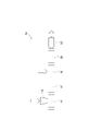
- FIG. 1 is a conceptual diagram showing the configuration of a twin-screw extruder used in the method for producing a thermoplastic resin composition of the present embodiment
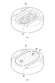
- FIG. FIG. 4 is a perspective view showing (a) a breaker plate and (b) a state in which a plate having a plurality of holes with a hole diameter of less than 7 mm is attached to the breaker plate.
- thermoplastic resin composition of the present embodiment when the thermoplastic resin and the fibrous filler are melt-kneaded in an extruder equipped with a die, the resin flow between the screw and the die of the extruder A plurality of channels each having an opening area of less than 38.47 mm 2 in the middle of the channel, wherein the total area of the openings of the plurality of channels is the surface area of the resin channel to which the openings of the plurality of channels belong. It is characterized by the provision of a plurality of channels that are less than 40% of the area.
- the extruder 10 shown in FIG. 1 comprises a cylinder divided into a first feed port 14 with a hopper 12 for charging thermoplastic resin, a plasticizing zone 16, a second feed port 18, and a kneading zone 20. .
- a screw (not shown) extending from the first supply port 14 to the kneading zone 20 is rotatably supported inside the cylinder.
- a die 22 is connected to the outside of the kneading zone 20 on the downstream side.
- Granular thermoplastic resin introduced into the first supply port 14 is transported as a solid to the plasticizing zone 16 , melted, and transported to the second supply port 18 .
- the second feed port 18 has, for example, a side feeder screw, from which the fibrous filler can be fed to the extruder 10 .
- the kneading zone 20 is located downstream of the second supply port 18 and is a zone for melt-kneading the plasticized thermoplastic resin and the fibrous filler.
- the melt-kneaded resin composition is discharged from a nozzle provided in the die 22 .
- a multi-screw extruder such as a single-screw extruder or a twin-screw extruder can be used as the extruder.
- a plurality of flow paths each having an opening area of less than 38.47 mm 2 are provided in the middle of the resin flow path between the screw and the die 22, and a plurality of A plurality of channels are provided in which the total area of the openings of the channels is less than 40% of the area of the surfaces in the resin channel to which the openings of the plurality of channels belong.
- the plurality of flow paths provided between the screw and the die 22 are for positively generating elongation stress in addition to shear stress. Since the entire amount of the resin containing the fibrous filler passes through this flow channel without fail, it receives the stress necessary for defibration without fail. Therefore, unlike the case where shear flow is generated by rotating the screw, the bundle of the fibrous filler can be sufficiently defibrated without increasing the effective length (L/D) of the screw.
- the plurality of channels provided between the screw and the die 22 are a plurality of channels each having an opening area of less than 38.47 mm 2 , but each channel having an opening area of 38.47 mm 2 or less. If the diameter exceeds 47 mm 2 , sufficient stress to defibrate the bundle of fibrous filler is not generated.
- the opening area of one channel is preferably 0.76 to 38.47 mm 2 , more preferably 3.14 to 28.26 mm 2 .
- a plurality of channels having different areas may be mixed as long as the channel has an opening area of less than 38.47 mm 2 . For example, of the plurality of channels, half of the channels may have an area of 19.63 mm 2 and the remaining channels may have an area of 6.98 mm 2 .
- the shape of the plurality of channel openings provided between the screw and the die 22 can be circular, elliptical, oval, or polygonal. If circular, a channel with an open area of 38.47 mm 2 is a channel with an opening of 7 mm diameter. A plurality of channels having different diameters may coexist as long as the channel has a circular opening with a diameter of less than 7 mm. For example, half of the plurality of channels may have a diameter of 5 mm and the remaining channels may have a diameter of 3 mm. Moreover, the length of the plurality of flow paths is preferably 2 to 15 mm.
- the total area of the openings of the plurality of channels is less than 40% of the area of the surface to which the openings of the plurality of channels belong in the resin channel. If the total area exceeds 40%, sufficient stress to defibrate the bundle of fibrous fillers is not generated.
- the total area of the openings of the plurality of channels is preferably 1 to 40%, more preferably 2 to 35%, of the surface area of the resin channel to which the openings of the plurality of channels belong.
- the number of the plurality of channels varies depending on the opening area of each channel and the total area of the surfaces in the resin channel to which the openings of the plurality of channels belong. and the total area of the openings of the channels is less than 40% of the total area of the surfaces in the resin channel to which the openings of the plurality of channels belong. is preferred. Also, if the melt viscosity of the thermoplastic resin is high, a load is applied during extrusion. Therefore, it is preferable to determine the number of flow paths according to the melt viscosity so as not to interfere with extrusion.
- a plurality of flow paths as described above are provided, for example, by inserting and fixing a plate having a predetermined thickness, which is provided with holes corresponding to the plurality of flow paths, between the screw and the die 22. be able to.
- FIG. 2(a) is a perspective view showing a breaker plate 40 having a plurality of holes 42.
- FIG. 2B is a perspective view showing a state in which a plate 44 provided with holes 46 having an opening area of less than 38.47 mm 2 corresponding to a plurality of flow paths is attached to the breaker plate 40 with bolts 48. It is a diagram. In FIG.
- the hole 46 of the plate 44 is positioned directly above the hole 42 provided in the breaker plate 40 (however, the hole provided with the bolt 48 is excluded). That is, when the breaker plate 40 to which the plate 44 is attached is viewed from above in the vertical direction, the center of the hole 42 and the center of the hole 46 match. When the breaker plate 40 shown in FIG. 2(a) is provided between the screw and the die 22, the opening area of the hole 42 of the breaker plate 40 is large, so sufficient stress is not generated. In contrast, when the plate 44 is attached to the breaker plate 40, the plurality of holes 46 formed in the plate 44, i.e., the plurality of channels, generate enough stress to defibrate the bundle of fibrous filler. do.
- thermoplastic resin composition of the present embodiment Each component used in the method for producing the thermoplastic resin composition of the present embodiment will be described below.
- thermoplastic resin In this embodiment, general-purpose plastics and engineering plastics can be used as the thermoplastic resin.
- Thermoplastic resins include polyarylene sulfide resin (PAS) such as polyphenylene sulfide resin (PPS), polybutylene terephthalate resin (PBT), polyacetal resin (POM), liquid crystalline polymer (LCP), polyethylene terephthalate resin (PET), polypropylene (PP), polyamide resin (PA) and the like.
- PPS polyarylene sulfide resin
- PPS polyphenylene sulfide resin
- PBT polybutylene terephthalate resin
- POM polyacetal resin
- LCP liquid crystalline polymer
- PET polyethylene terephthalate resin
- PP polypropylene
- PA polyamide resin
- fibrous fillers examples include glass fiber, carbon fiber, silicon carbide fiber, alumina fiber, silicon carbide whisker, silicon nitride whisker, potassium titanate whisker, and wollastonite. Among them, when glass fiber is used, the effect of the manufacturing method of the present embodiment is remarkable.
- thermoplastic resins such as lubricants, release agents, antistatic agents, surfactants, flame retardants, or organic polymeric materials, inorganic or organic 1 or 2 or more of powdery or plate-like fillers can be added.
- Tables 1 and 2 show the total area of the openings of the plurality of channels with respect to the area of the surface to which the openings of the plurality of channels belong in the resin channel as an aperture ratio.
- screw spacing means the distance between the rotation centers of a pair of screws.
- Extruder Extruder
- Extruder A Japan Steel Works, Ltd., TEX30 ⁇ (cylinder diameter: 32 mm, screw spacing: 24 mm)
- Extruder B Japan Steel Works, Ltd., TEX44 ⁇ (cylinder diameter: 47 mm, screw spacing: 38.5 mm)
- Example extrusion amount 10 kg ⁇ Cylinder temperature: 320°C ⁇ Discharge amount per unit time: shown in Tables 1 and 2 ⁇ Screw rotation speed: shown in Tables 1 and 2
- PPS resin A Fortron KPS manufactured by Kureha Co., Ltd. (melt viscosity: 30 Pa s (shear rate: 1200 sec -1 , 310 ° C.))
- PPS resin B Fortron KPS manufactured by Kureha Co., Ltd. (melt viscosity: 130 Pa s (shear rate: 1200 sec ⁇ 1 , 310° C.))
- Melt viscosity of PPS resin was measured as follows. The melt viscosity was measured at a cylinder temperature of 310° C.
Landscapes
- Engineering & Computer Science (AREA)
- Mechanical Engineering (AREA)
- Extrusion Moulding Of Plastics Or The Like (AREA)
- Reinforced Plastic Materials (AREA)
- Compositions Of Macromolecular Compounds (AREA)
- Processing And Handling Of Plastics And Other Materials For Molding In General (AREA)
Abstract
熱可塑性樹脂と繊維状充填材とを、ダイを備える押出機にて溶融混練する際に、押出機のスクリューとダイとの間の樹脂流路途中に、それぞれの開口面積が38.47mm2未満の複数の流路であって、複数の流路の開口の合計面積が、樹脂流路内における、複数の流路の開口が属する面の面積の40%未満である複数の流路を設ける、熱可塑性樹脂組成物の製造方法である。
Description
本発明は、繊維状充填材を含む熱可塑性樹脂組成物の製造方法に関する。
熱可塑性樹脂は、成形性、機械特性、又は耐候性等の性能に優れることから、射出成形用途を中心として、各種自動車部品、電気・電子部品などの用途に広く使用されている。
一般に、熱可塑性樹脂において上記のような性能を更に向上させたり、熱可塑性樹脂の短所を補ったりするため、種々の添加剤を添加して樹脂組成物として用いられる。
一般に、熱可塑性樹脂において上記のような性能を更に向上させたり、熱可塑性樹脂の短所を補ったりするため、種々の添加剤を添加して樹脂組成物として用いられる。
例えば、樹脂組成物又はその成形品の機械強度の向上を図るために、ガラス繊維等の繊維状充填材が添加される。繊維状充填材を含有するペレットを作製する場合、通常、熱可塑性樹脂と、複数本の繊維状充填材を一つの束にして、数mmの長さでカットしたもの(チョップドストランドとも呼ばれる)とを押出機で溶融混練して作製する。そして、溶融混練時に複数本の繊維状充填材のそれぞれが分散された状態(繊維状充填材の束が解繊された状態)となる。
ところが、繊維状充填材の束の中には解繊が不十分な状態で残存する場合がある。解繊が不十分な状態の束状として存在する繊維状充填材は射出成形の際にノズルの詰まりの原因となったり、成形品としたときに強度低下を招いたりする等の悪影響が危惧されるため、繊維状充填材の束は十分に解繊されることが望まれる。
押出機内での溶融混練時に繊維状充填材の束が解繊されるのは、押出機内で発生するせん断流動に由来する応力が寄与していると考えられる。そこで、本出願人は、その点に着目し、ガラス繊維束を十分に解繊し得る、樹脂組成物ペレットの製造方法を提案した(特許文献1参照)。より具体的には、押出機の押出条件(Q(吐出量)とNs(スクリュー回転数))とスクリューデザインの組み合わせの最適化を行い、最小せん断応力履歴値Tminを制御することで、ガラス繊維束を十分に解繊するものである。
しかしながら、押出機のスクリュー回転に伴い生じる応力による繊維状充填材の束の解繊は、次のような課題がある。繊維状充填材の全量に対し、くまなく解繊に必要な応力が付加されなかった場合、未解繊物が生じる。特に、製造効率を上げるために高い吐出量を設定した場合、この不良が生じやすい。繊維状充填材の束を十分に解繊するには、例えば、押出機におけるスクリューの有効長(L/D(L:スクリューの長さ、D:スクリューの直径))を大きくすることが考えられる。しかし、そのようにすると、押出機が大型化し、清掃やメンテナンス等、装置管理上の労力を要したり、広大な設置スペースが必要となったりする。或いは、高いスクリュー回転数に設定することで、発生応力を高めるようとすると、樹脂へのせん断発熱負荷が過大となり、樹脂分解を引き起こす。すなわち、スクリュー回転による応力により繊維状充填材の束を十分に解繊することは可能ではあるものの、これのみにて未解繊不良を抑制しようとすると押出機の制約や樹脂分解が課題となりうるため、これら以外による方策が望まれる。
本発明は、繊維状充填材を含む熱可塑性樹脂組成物における未解繊の束状の繊維状充填材を、簡便に低減し得る熱可塑性樹脂組成物の製造方法を提供することにある。
前記課題を解決する本発明の一態様は以下の通りである。
(1)熱可塑性樹脂と繊維状充填材とを、ダイを備える押出機にて溶融混練する際に、前記押出機のスクリューと前記ダイとの間の樹脂流路途中に、それぞれの開口面積が38.47mm2未満の複数の流路であって、前記複数の流路の開口の合計面積が前記樹脂流路内における、前記複数の流路の開口が属する面の面積の40%未満である複数の流路を設ける、熱可塑性樹脂組成物の製造方法。
(1)熱可塑性樹脂と繊維状充填材とを、ダイを備える押出機にて溶融混練する際に、前記押出機のスクリューと前記ダイとの間の樹脂流路途中に、それぞれの開口面積が38.47mm2未満の複数の流路であって、前記複数の流路の開口の合計面積が前記樹脂流路内における、前記複数の流路の開口が属する面の面積の40%未満である複数の流路を設ける、熱可塑性樹脂組成物の製造方法。
(2)前記繊維状充填材がガラス繊維である、前記(1)に記載の熱可塑性樹脂組成物の製造方法。
本発明によれば、繊維状充填材を含む熱可塑性樹脂組成物における未解繊の繊維状充填材を、簡便に低減し得る熱可塑性樹脂組成物の製造方法を提供することができる。
本実施形態の熱可塑性樹脂組成物の製造方法は、熱可塑性樹脂と繊維状充填材とを、ダイを備える押出機にて溶融混練する際に、押出機のスクリューとダイとの間の樹脂流路途中に、それぞれの開口面積が38.47mm2未満の複数の流路であって、複数の流路の開口の合計面積が、樹脂流路内における、複数の流路の開口が属する面の面積の40%未満である複数の流路を設けることを特徴としている。
本実施形態の熱可塑性樹脂組成物の製造方法において使用する押出機の一例について、図1を参照して説明する。図1に示す押出機10は、熱可塑性樹脂を投入するためのホッパー12を備える第1供給口14、可塑化ゾーン16、第2供給口18、及び混練ゾーン20に分画されるシリンダーを備える。そして、シリンダーの内部には、第1供給口14から混練ゾーン20にわたって延在するスクリュー(不図示)が回転駆動可能に支持されている。また、混練ゾーン20の下流側外部には、ダイ22が接続されている。第1供給口14に投入される粒状の熱可塑性樹脂は、可塑化ゾーン16に固体搬送され溶融されて第2供給口18へ搬送される。熱可塑性樹脂の大部分の溶融が見込まれれば可塑化ゾーン16のエレメント構成に制限はない。
第2供給口18は、例えば、サイドフィーダースクリューを有し、ここから繊維状充填材を押出機10へ供給することができる。
混練ゾーン20は、第2供給口18の下流側に位置し、可塑化を終えた熱可塑性樹脂と繊維状充填材とを溶融混練するゾーンである。溶融混練された樹脂組成物はダイ22に設けられたノズルから吐出される。
なお、本実施形態においては、押出機としては、単軸押出機、二軸押出機等の多軸押出機を使用することができる。
第2供給口18は、例えば、サイドフィーダースクリューを有し、ここから繊維状充填材を押出機10へ供給することができる。
混練ゾーン20は、第2供給口18の下流側に位置し、可塑化を終えた熱可塑性樹脂と繊維状充填材とを溶融混練するゾーンである。溶融混練された樹脂組成物はダイ22に設けられたノズルから吐出される。
なお、本実施形態においては、押出機としては、単軸押出機、二軸押出機等の多軸押出機を使用することができる。
本実施形態においては、上記のような押出機10において、スクリューとダイ22との間の樹脂流路途中に、それぞれの開口面積が38.47mm2未満の複数の流路であって、複数の流路の開口の合計面積が、樹脂流路内における、複数の流路の開口が属する面の面積の40%未満である複数の流路が設けられる。
本実施形態において、スクリューとダイ22との間に設けられる上記複数の流路は、せん断応力に加え、積極的に伸長応力を発生させるためのものである。繊維状充填材を含んだ樹脂の全量が、もれなくこの流路を通過するため、取りこぼしなく解繊に必要な応力を受けることとなる。従って、スクリュー回転によるせん断流動を発生させる場合とは異なり、スクリューの有効長(L/D)を大きくすることなく、繊維状充填材の束を十分に解繊することができる。
本実施形態において、スクリューとダイ22との間に設けられる複数の流路は、それぞれの開口面積が38.47mm2未満の複数の流路であるが、それぞれの流路の開口面積が38.47mm2を超えると、繊維状充填材の束を十分に解繊する程度の応力が発生しない。1つの流路の開口面積は、0.76~38.47mm2が好ましく、3.14~28.26mm2がより好ましい。なお、開口面積が38.47mm2未満の流路であれば、面積が異なる複数の流路が混在してもよい。例えば、複数の流路のうち、半数の流路の面積が19.63mm2で、残りの流路の面積が6.98mm2のようにしてもよい。
スクリューとダイ22との間に設けられる複数の流路の開口の形状は、円形、楕円形、長円形、多角形とすることができる。円形の場合、開口面積が38.47mm2の流路は、直径7mmの開口を有する流路である。そして、直径が7mm未満の円形開口の流路であれば、直径が異なる複数の流路が混在してもよい。例えば、複数の流路のうち、半数の流路の直径が5mmで、残りの流路の直径が3mmのようにしてもよい。
また、複数の流路の長さは、2~15mmとすることが好ましい。
また、複数の流路の長さは、2~15mmとすることが好ましい。
また、本実施形態において、複数の流路の開口の合計面積は、樹脂流路内における、複数の流路の開口が属する面の面積の40%未満であるが、複数の流路の開口の合計面積が40%を超えると、繊維状充填材の束を十分に解繊する程度の応力が発生しない。複数の流路の開口の合計面積は、樹脂流路内における、複数の流路の開口が属する面の面積の1~40%が好ましく、2~35%がより好ましい。
複数の流路の個数としては、それぞれの流路の開口面積と、樹脂流路内における複数の流路の開口が属する面の全面積とにより変動するため、それぞれの開口面積が38.47mm2未満の複数の流路であり、かつ、流路の開口の合計面積が、樹脂流路内における複数の流路の開口が属する面の全面積の40%未満であることを満たすように決定することが好ましい。
また、熱可塑性樹脂の溶融粘度が大きいと押出時に負荷がかかるため、押出に支障がないように、溶融粘度に応じて流路の個数を決定することが好ましい。
また、熱可塑性樹脂の溶融粘度が大きいと押出時に負荷がかかるため、押出に支障がないように、溶融粘度に応じて流路の個数を決定することが好ましい。
以上のような複数の流路は、例えば、複数の流路に相当する孔が設けられた、所定の厚さを有するプレートを、スクリューとダイ22との間に挿入して固定することにより設けることができる。
一方、スクリューとダイ22との間にブレーカープレートが存在する場合、当該ブレーカープレートのスクリュー側に、上記のような、複数の流路に相当する孔(開口)が設けられたプレートを装着してもよい。そのような形態について図2を参照して説明する。図2(a)は、複数の孔42を有するブレーカープレート40を示す斜視図である。また、図2(b)は、複数の流路に相当する、開口面積が38.47mm2未満の孔46が設けられたプレート44が、ボルト48によりブレーカープレート40に装着された状態を示す斜視図である。なお、図2(b)において、ブレーカープレート40に設けられた孔42の直上にプレート44の孔46が位置している(ただし、ボルト48が設けられた孔を除く。)。つまり、プレート44が装着されたブレーカープレート40を垂直方向上方から目視したとき、孔42の中心と孔46の中心とは一致している。
図2(a)に示すブレーカープレート40が、スクリューとダイ22との間に設けられた場合、ブレーカープレート40の孔42は開口面積が大きいため応力は十分に発生しない。それに対して、ブレーカープレート40にプレート44を装着した場合、プレート44に形成された複数の孔46により、すなわち複数の流路により繊維状充填材の束を解繊するのに十分な応力が発生する。
図2(a)に示すブレーカープレート40が、スクリューとダイ22との間に設けられた場合、ブレーカープレート40の孔42は開口面積が大きいため応力は十分に発生しない。それに対して、ブレーカープレート40にプレート44を装着した場合、プレート44に形成された複数の孔46により、すなわち複数の流路により繊維状充填材の束を解繊するのに十分な応力が発生する。
以下に、本実施形態の熱可塑性樹脂組成物の製造方法に用いられる各成分について説明する。
[熱可塑性樹脂]
本実施形態において、熱可塑性樹脂としては汎用プラスチックやエンジニアリングプラスチックを使用することができる。熱可塑性樹脂としては、ポリフェニレンサルファイド樹脂(PPS)等のポリアリーレンサルファイド樹脂(PAS)、ポリブチレンテレフタレート樹脂(PBT)、ポリアセタール樹脂(POM)、液晶性ポリマー(LCP)、ポリエチレンテレフタレート樹脂(PET)、ポリプロピレン(PP)、ポリアミド樹脂(PA)等が挙げられる。
本実施形態において、熱可塑性樹脂としては汎用プラスチックやエンジニアリングプラスチックを使用することができる。熱可塑性樹脂としては、ポリフェニレンサルファイド樹脂(PPS)等のポリアリーレンサルファイド樹脂(PAS)、ポリブチレンテレフタレート樹脂(PBT)、ポリアセタール樹脂(POM)、液晶性ポリマー(LCP)、ポリエチレンテレフタレート樹脂(PET)、ポリプロピレン(PP)、ポリアミド樹脂(PA)等が挙げられる。
[繊維状充填材]
繊維状充填材としては、ガラス繊維、炭素繊維、炭化ケイ素繊維、アルミナ繊維、炭化ケイ素ウィスカー、窒化ケイ素ウィスカー、チタン酸カリウムウィスカー、ウオラストナイト等が挙げられる。中でも、ガラス繊維を用いた場合、本実施形態の製造方法の効果が顕著である。
繊維状充填材としては、ガラス繊維、炭素繊維、炭化ケイ素繊維、アルミナ繊維、炭化ケイ素ウィスカー、窒化ケイ素ウィスカー、チタン酸カリウムウィスカー、ウオラストナイト等が挙げられる。中でも、ガラス繊維を用いた場合、本実施形態の製造方法の効果が顕著である。
[他の成分]
本実施形態においては、必要に応じて、熱可塑性樹脂に対する一般的な添加剤、例えば、滑剤、離型剤、帯電防止剤、界面活性剤、難燃剤、又は、有機高分子材料、無機若しくは有機の粉体状、板状の充填材等を1種又は2種以上添加することができる。
本実施形態においては、必要に応じて、熱可塑性樹脂に対する一般的な添加剤、例えば、滑剤、離型剤、帯電防止剤、界面活性剤、難燃剤、又は、有機高分子材料、無機若しくは有機の粉体状、板状の充填材等を1種又は2種以上添加することができる。
以下に、実施例により本実施形態をさらに具体的に説明するが、本実施形態は以下の実施例に限定されるものではない。
[実施例1~8、比較例1~8]
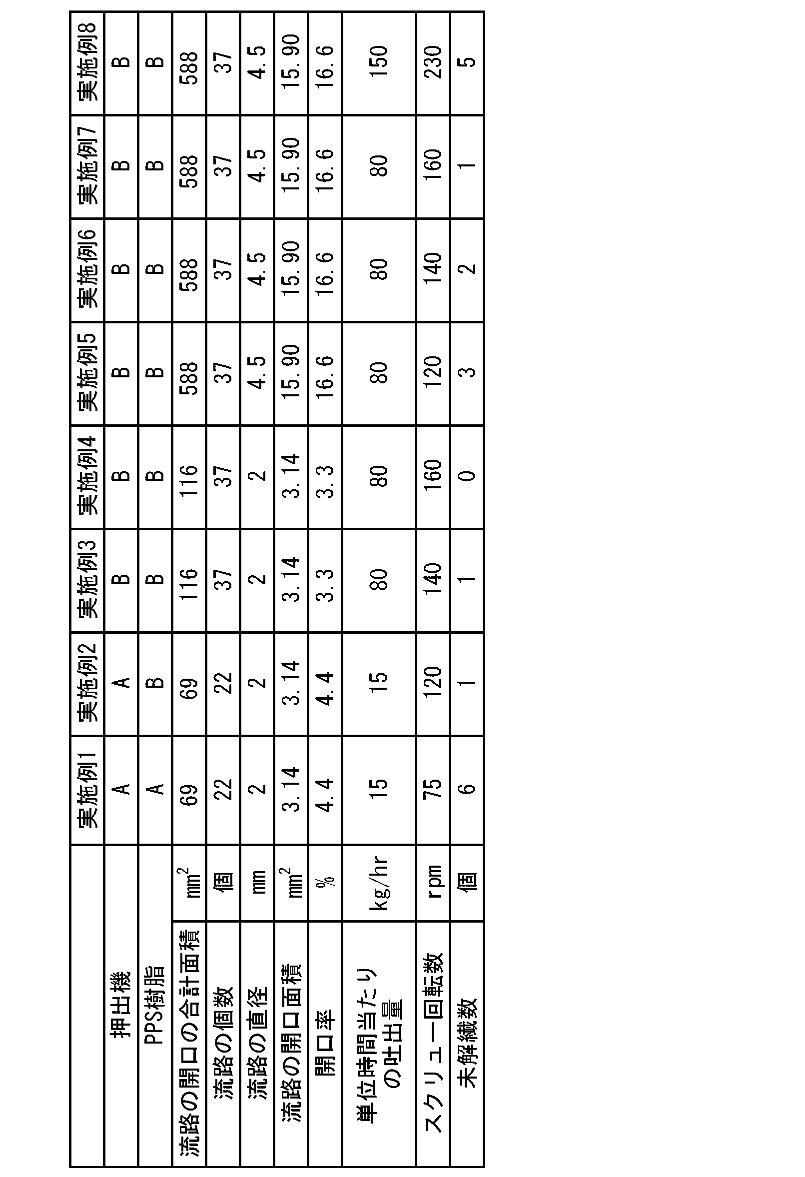
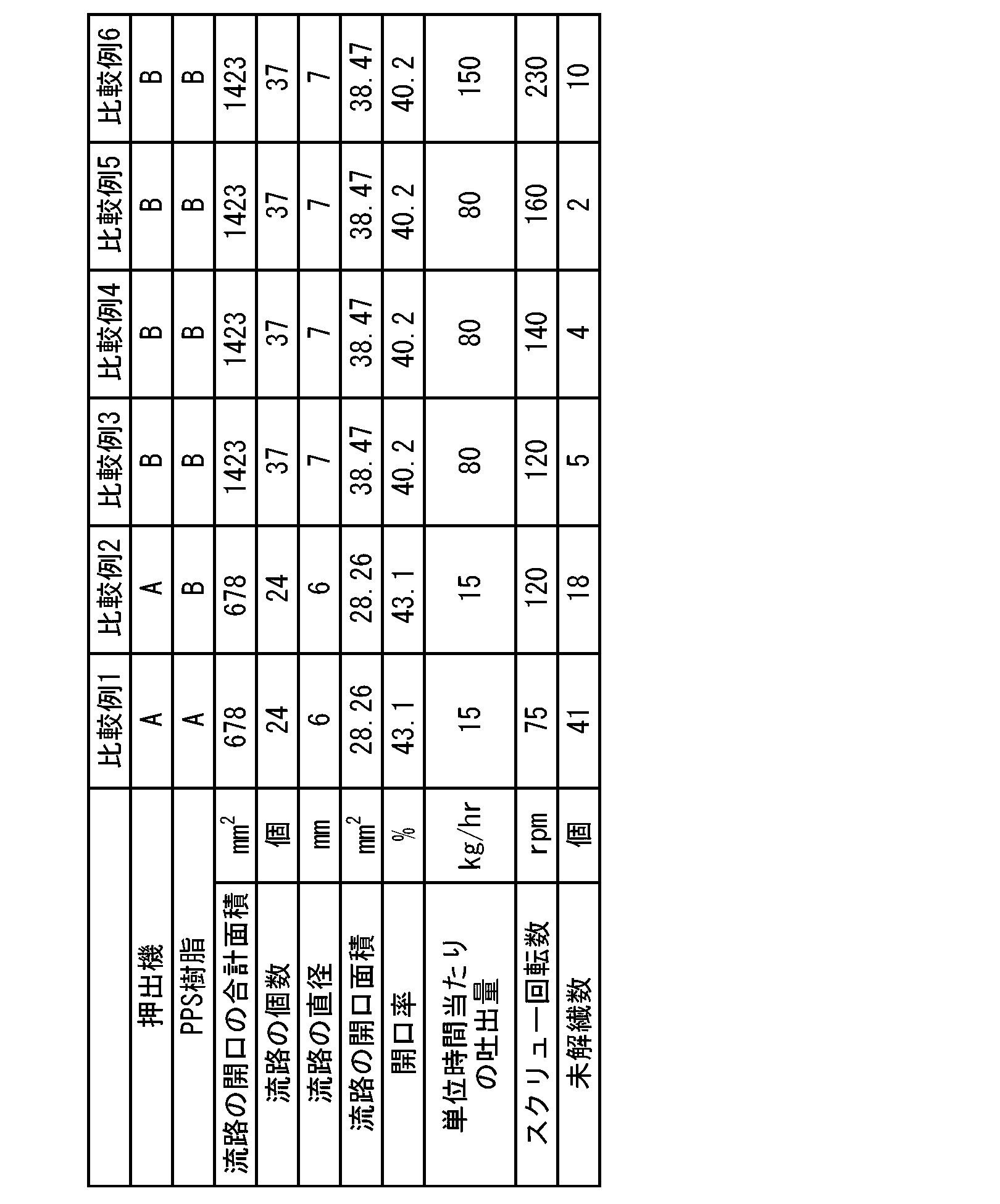
各実施例・比較例において、以下に示す二軸押出機(押出機A又はB)に、第一投入部からポリフェニレンサルファイド樹脂(PPS樹脂A又はB)100質量部と、第二投入部からガラス繊維(繊維状充填材)66.7質量部とを投入して、以下の押出条件にて溶融混練し、樹脂ペレットを得た。なお、使用した二軸押出機には、スクリューとダイとの間に設けられたブレーカープレートのスクリュー側に、所定の開口面積を有する複数の流路に相当する孔が設けられたプレート(厚さ:5mm)を装着して用いた。各実施例・比較例における、当該プレートにおける孔数、孔径(直径)及び開口面積を表1~2に示す。また、樹脂流路内における、複数の流路の開口が属する面の面積に対する複数の流路の開口の合計面積を開口率として表1~2に示す。開口率は、以下の式により求めた。
開口率={(各孔の面積)×(孔数)}÷{2×1/2×(シリンダーの断面積)+(スクリュー間隔)×(シリンダー径)}
上記式中、「スクリュー間隔」は、一対のスクリューの回転中心間の距離を意味する。
各実施例・比較例において、以下に示す二軸押出機(押出機A又はB)に、第一投入部からポリフェニレンサルファイド樹脂(PPS樹脂A又はB)100質量部と、第二投入部からガラス繊維(繊維状充填材)66.7質量部とを投入して、以下の押出条件にて溶融混練し、樹脂ペレットを得た。なお、使用した二軸押出機には、スクリューとダイとの間に設けられたブレーカープレートのスクリュー側に、所定の開口面積を有する複数の流路に相当する孔が設けられたプレート(厚さ:5mm)を装着して用いた。各実施例・比較例における、当該プレートにおける孔数、孔径(直径)及び開口面積を表1~2に示す。また、樹脂流路内における、複数の流路の開口が属する面の面積に対する複数の流路の開口の合計面積を開口率として表1~2に示す。開口率は、以下の式により求めた。
開口率={(各孔の面積)×(孔数)}÷{2×1/2×(シリンダーの断面積)+(スクリュー間隔)×(シリンダー径)}
上記式中、「スクリュー間隔」は、一対のスクリューの回転中心間の距離を意味する。
(押出機)
押出機A:日本製鋼所(株)製、TEX30α(シリンダー径:32mm、スクリュー間隔:24mm)
押出機B:日本製鋼所(株)製、TEX44α(シリンダー径:47mm、スクリュー間隔:38.5mm)
押出機A:日本製鋼所(株)製、TEX30α(シリンダー径:32mm、スクリュー間隔:24mm)
押出機B:日本製鋼所(株)製、TEX44α(シリンダー径:47mm、スクリュー間隔:38.5mm)
(押出条件)
・サンプル押出量:10kg
・シリンダー温度:320℃
・単位時間当たりの吐出量:表1~2に示す
・スクリュー回転数:表1~2に示す
・サンプル押出量:10kg
・シリンダー温度:320℃
・単位時間当たりの吐出量:表1~2に示す
・スクリュー回転数:表1~2に示す
また、使用した各成分の詳細は以下の通りである。
(1)ポリフェニレンサルファイド樹脂
PPS樹脂A:(株)クレハ製、フォートロンKPS(溶融粘度:30Pa・s(せん断速度:1200sec-1、310℃))
PPS樹脂B:(株)クレハ製、フォートロンKPS(溶融粘度:130Pa・s(せん断速度:1200sec-1、310℃))
(PPS樹脂の溶融粘度の測定)
上記PPS樹脂の溶融粘度は以下のようにして測定した。
(株)東洋精機製作所製キャピログラフを用い、キャピラリーとして口径:1mm、長さ:20mmのフラットダイを使用し、シリンダー温度310℃、せん断速度1200sec-1での溶融粘度を測定した。
(2)ガラス繊維
日本電気硝子(株)製、ガラス繊維、ECS03T-651G(繊維径10.0μmのガラス繊維の長さ3mmのチョップドストランド)
PPS樹脂A:(株)クレハ製、フォートロンKPS(溶融粘度:30Pa・s(せん断速度:1200sec-1、310℃))
PPS樹脂B:(株)クレハ製、フォートロンKPS(溶融粘度:130Pa・s(せん断速度:1200sec-1、310℃))
(PPS樹脂の溶融粘度の測定)
上記PPS樹脂の溶融粘度は以下のようにして測定した。
(株)東洋精機製作所製キャピログラフを用い、キャピラリーとして口径:1mm、長さ:20mmのフラットダイを使用し、シリンダー温度310℃、せん断速度1200sec-1での溶融粘度を測定した。
(2)ガラス繊維
日本電気硝子(株)製、ガラス繊維、ECS03T-651G(繊維径10.0μmのガラス繊維の長さ3mmのチョップドストランド)
[ガラス繊維の未解繊数評価]
各実施例・比較例で得られたペレット状の樹脂組成物に対し、以下のX線CT装置(コムスキャンテクノ(株)製、ScanXmate-D090SS270)を用い、以下の測定条件にて未解繊のガラス繊維の個数を計数した。具体的には、各樹脂ペレット9gをサンプルセルに入れ、X線CT透過像を撮影し、輝度が高く映る未解繊のガラス繊維束の個数を計数した。計数結果を表1~2に示す。
(測定条件)
管電圧:52kV
管電流:157μA
ボクセルサイズ:26μm
各実施例・比較例で得られたペレット状の樹脂組成物に対し、以下のX線CT装置(コムスキャンテクノ(株)製、ScanXmate-D090SS270)を用い、以下の測定条件にて未解繊のガラス繊維の個数を計数した。具体的には、各樹脂ペレット9gをサンプルセルに入れ、X線CT透過像を撮影し、輝度が高く映る未解繊のガラス繊維束の個数を計数した。計数結果を表1~2に示す。
(測定条件)
管電圧:52kV
管電流:157μA
ボクセルサイズ:26μm
表1~2より、孔径と開口率とを異ならせ、それら以外の条件を同じとした実施例1及び比較例1、実施例2及び比較例2の比較から、スクリューとダイとの間の複数の流路の開口面積及び開口率を所定の範囲内とするとガラス繊維束の未解繊数を低減できることが分かる。また、孔径と開口率とを異ならせ、それら以外の条件を同じとした実施例3及び4、実施例6及び7の比較から、スクリューとダイとの間の複数の流路の開口面積及び開口率が小さいほどガラス繊維の未解繊数をより低減できることが分かる。
同様に、孔径と開口率とを異ならせ、それら以外の条件を同じとした、実施例5及び比較例3、実施例6及び比較例4、実施例7及び比較例5、実施例8及び比較例6の比較から、スクリューとダイとの間の複数の流路の開口面積及び開口率を所定の範囲内とするとガラス繊維束の未解繊数を低減できることが分かる。
同様に、孔径と開口率とを異ならせ、それら以外の条件を同じとした、実施例5及び比較例3、実施例6及び比較例4、実施例7及び比較例5、実施例8及び比較例6の比較から、スクリューとダイとの間の複数の流路の開口面積及び開口率を所定の範囲内とするとガラス繊維束の未解繊数を低減できることが分かる。
Claims (2)
- 熱可塑性樹脂と繊維状充填材とを、ダイを備える押出機にて溶融混練する際に、前記押出機のスクリューと前記ダイとの間の樹脂流路途中に、それぞれの開口面積が38.47mm2未満の複数の流路であって、前記複数の流路の開口の合計面積が、前記樹脂流路内における、前記複数の流路の開口が属する面の面積の40%未満である複数の流路を設ける、熱可塑性樹脂組成物の製造方法。
- 前記繊維状充填材がガラス繊維である、請求項1に記載の熱可塑性樹脂組成物の製造方法。
Applications Claiming Priority (2)
| Application Number | Priority Date | Filing Date | Title |
|---|---|---|---|
| JP2021-053952 | 2021-03-26 | ||
| JP2021053952A JP7168714B2 (ja) | 2021-03-26 | 2021-03-26 | 熱可塑性樹脂組成物の製造方法 |
Publications (1)
| Publication Number | Publication Date |
|---|---|
| WO2022202096A1 true WO2022202096A1 (ja) | 2022-09-29 |
Family
ID=83395581
Family Applications (1)
| Application Number | Title | Priority Date | Filing Date |
|---|---|---|---|
| PCT/JP2022/007849 Ceased WO2022202096A1 (ja) | 2021-03-26 | 2022-02-25 | 熱可塑性樹脂組成物の製造方法 |
Country Status (2)
| Country | Link |
|---|---|
| JP (1) | JP7168714B2 (ja) |
| WO (1) | WO2022202096A1 (ja) |
Citations (4)
| Publication number | Priority date | Publication date | Assignee | Title |
|---|---|---|---|---|
| WO2007007831A1 (ja) * | 2005-07-14 | 2007-01-18 | Mitsui Chemicals, Inc. | ブレーカープレートおよびこれを用いた熱可塑性樹脂組成物の造粒方法 |
| JP2010023464A (ja) * | 2008-07-24 | 2010-02-04 | Sumitomo Chemical Co Ltd | ポリオレフィン系樹脂組成物の製造方法及びこれに用いる濾過装置 |
| WO2017010246A1 (ja) * | 2015-07-16 | 2017-01-19 | 日本スピンドル製造株式会社 | ストレーニング機構及びそのストレーニング機構を備えたスクリュー押出機 |
| WO2017145985A1 (ja) * | 2016-02-24 | 2017-08-31 | 三菱ケミカル株式会社 | 多穴型押出ダイス、金属化合物押出成形体の製造方法、不飽和アルデヒドおよび/または不飽和カルボン酸製造用触媒押出成形体の製造方法、ならびに不飽和アルデヒドおよび/または不飽和カルボン酸の製造方法 |
Family Cites Families (1)
| Publication number | Priority date | Publication date | Assignee | Title |
|---|---|---|---|---|
| JP2009107326A (ja) | 2007-10-12 | 2009-05-21 | Tokai Kogyo Co Ltd | 長尺材の製造方法と製造装置 |
-
2021
- 2021-03-26 JP JP2021053952A patent/JP7168714B2/ja active Active
-
2022
- 2022-02-25 WO PCT/JP2022/007849 patent/WO2022202096A1/ja not_active Ceased
Patent Citations (4)
| Publication number | Priority date | Publication date | Assignee | Title |
|---|---|---|---|---|
| WO2007007831A1 (ja) * | 2005-07-14 | 2007-01-18 | Mitsui Chemicals, Inc. | ブレーカープレートおよびこれを用いた熱可塑性樹脂組成物の造粒方法 |
| JP2010023464A (ja) * | 2008-07-24 | 2010-02-04 | Sumitomo Chemical Co Ltd | ポリオレフィン系樹脂組成物の製造方法及びこれに用いる濾過装置 |
| WO2017010246A1 (ja) * | 2015-07-16 | 2017-01-19 | 日本スピンドル製造株式会社 | ストレーニング機構及びそのストレーニング機構を備えたスクリュー押出機 |
| WO2017145985A1 (ja) * | 2016-02-24 | 2017-08-31 | 三菱ケミカル株式会社 | 多穴型押出ダイス、金属化合物押出成形体の製造方法、不飽和アルデヒドおよび/または不飽和カルボン酸製造用触媒押出成形体の製造方法、ならびに不飽和アルデヒドおよび/または不飽和カルボン酸の製造方法 |
Also Published As
| Publication number | Publication date |
|---|---|
| JP2022151055A (ja) | 2022-10-07 |
| JP7168714B2 (ja) | 2022-11-09 |
Similar Documents
| Publication | Publication Date | Title |
|---|---|---|
| CN108219266B (zh) | 一种消除聚丙烯组合物虎皮纹缺陷的方法及其制备的聚丙烯组合物 | |
| US5264174A (en) | Process for producing compositely reinforced polypropylene resin composition | |
| US7993737B2 (en) | Natural fiber-reinforced thermoplastic resin injection molding | |
| CN101193953A (zh) | 制备纤维增强的聚丙烯复合物的方法 | |
| JPWO2006123824A1 (ja) | 繊維状充填剤高濃度配合樹脂組成物の製造方法及び樹脂組成物ペレット | |
| US20180223054A1 (en) | Thermoplastic resin composition, method for producing thermoplastic resin composition, and molded body | |
| JP2008238626A (ja) | 熱可塑性樹脂組成物の製造方法 | |
| JP7168714B2 (ja) | 熱可塑性樹脂組成物の製造方法 | |
| CN201338379Y (zh) | 制备粘土改性的聚烯烃复合物的螺杆挤出机 | |
| JP7792513B2 (ja) | 熱可塑性樹脂組成物の製造方法 | |
| JP7603507B2 (ja) | 強化繊維含有樹脂ペレットの製造方法 | |
| JP5032244B2 (ja) | 繊維強化熱可塑性樹脂組成物の製造装置およびその製造方法 | |
| KR20150123370A (ko) | 섬유 강화 플라스틱 복합재 및 이의 제조방법 | |
| JPH0526642B2 (ja) | ||
| JP7361240B2 (ja) | 熱可塑性樹脂組成物の製造方法 | |
| KR101582590B1 (ko) | 고분자/하이브리드 전도성 필러의 전기 전도성 복합재료 및 이의 제조방법 | |
| JP7073115B2 (ja) | ペレット | |
| KR100419990B1 (ko) | 폴리페닐렌 설파이드계 열가소성 수지 조성물의 제조방법 | |
| JP6821354B2 (ja) | 二軸押出機 | |
| CN101365738B (zh) | 长纤维增强聚烯烃树脂成形材料的制造方法 | |
| JP7668667B2 (ja) | 強化繊維含有樹脂ペレット | |
| JP2020147006A (ja) | サイドフィーダー、押出機、および熱可塑性樹脂組成物の製造方法 | |
| JPS61254629A (ja) | 集束炭素繊維及びそれから形成された短繊維チツプ | |
| JPH0692508B2 (ja) | 長繊維強化ポリオレフィン樹脂組成物 | |
| WO2024232397A1 (ja) | 樹脂組成物の製造方法及び樹脂組成物 |
Legal Events
| Date | Code | Title | Description |
|---|---|---|---|
| 121 | Ep: the epo has been informed by wipo that ep was designated in this application |
Ref document number: 22774894 Country of ref document: EP Kind code of ref document: A1 |
|
| NENP | Non-entry into the national phase |
Ref country code: DE |
|
| 122 | Ep: pct application non-entry in european phase |
Ref document number: 22774894 Country of ref document: EP Kind code of ref document: A1 |