WO2022201982A1 - ロック機構、及びロック機構を備える画像形成装置 - Google Patents
ロック機構、及びロック機構を備える画像形成装置 Download PDFInfo
- Publication number
- WO2022201982A1 WO2022201982A1 PCT/JP2022/006115 JP2022006115W WO2022201982A1 WO 2022201982 A1 WO2022201982 A1 WO 2022201982A1 JP 2022006115 W JP2022006115 W JP 2022006115W WO 2022201982 A1 WO2022201982 A1 WO 2022201982A1
- Authority
- WO
- WIPO (PCT)
- Prior art keywords
- hook
- coil spring
- torsion coil
- engaging
- hook member
- Prior art date
- Legal status (The legal status is an assumption and is not a legal conclusion. Google has not performed a legal analysis and makes no representation as to the accuracy of the status listed.)
- Ceased
Links
Images





Classifications
-
- G—PHYSICS
- G03—PHOTOGRAPHY; CINEMATOGRAPHY; ANALOGOUS TECHNIQUES USING WAVES OTHER THAN OPTICAL WAVES; ELECTROGRAPHY; HOLOGRAPHY
- G03G—ELECTROGRAPHY; ELECTROPHOTOGRAPHY; MAGNETOGRAPHY
- G03G21/00—Arrangements not provided for by groups G03G13/00 - G03G19/00, e.g. cleaning, elimination of residual charge
- G03G21/16—Mechanical means for facilitating the maintenance of the apparatus, e.g. modular arrangements
- G03G21/1604—Arrangement or disposition of the entire apparatus
- G03G21/1623—Means to access the interior of the apparatus
- G03G21/1633—Means to access the interior of the apparatus using doors or covers
-
- E—FIXED CONSTRUCTIONS
- E05—LOCKS; KEYS; WINDOW OR DOOR FITTINGS; SAFES
- E05B—LOCKS; ACCESSORIES THEREFOR; HANDCUFFS
- E05B57/00—Locks in which a pivoted latch is used also as locking means
-
- E—FIXED CONSTRUCTIONS
- E05—LOCKS; KEYS; WINDOW OR DOOR FITTINGS; SAFES
- E05B—LOCKS; ACCESSORIES THEREFOR; HANDCUFFS
- E05B65/00—Locks or fastenings for special use
- E05B65/006—Locks or fastenings for special use for covers or panels
-
- E—FIXED CONSTRUCTIONS
- E05—LOCKS; KEYS; WINDOW OR DOOR FITTINGS; SAFES
- E05C—BOLTS OR FASTENING DEVICES FOR WINGS, SPECIALLY FOR DOORS OR WINDOWS
- E05C3/00—Fastening devices with bolts moving pivotally or rotatively
- E05C3/006—Fastening devices with bolts moving pivotally or rotatively about an axis parallel to the surface on which the fastener is mounted
- E05C3/008—Fastening devices with bolts moving pivotally or rotatively about an axis parallel to the surface on which the fastener is mounted parallel to the wing edge
-
- E—FIXED CONSTRUCTIONS
- E05—LOCKS; KEYS; WINDOW OR DOOR FITTINGS; SAFES
- E05C—BOLTS OR FASTENING DEVICES FOR WINGS, SPECIALLY FOR DOORS OR WINDOWS
- E05C3/00—Fastening devices with bolts moving pivotally or rotatively
- E05C3/12—Fastening devices with bolts moving pivotally or rotatively with latching action
- E05C3/14—Fastening devices with bolts moving pivotally or rotatively with latching action with operating handle or equivalent member rigid with the latch
-
- G—PHYSICS
- G03—PHOTOGRAPHY; CINEMATOGRAPHY; ANALOGOUS TECHNIQUES USING WAVES OTHER THAN OPTICAL WAVES; ELECTROGRAPHY; HOLOGRAPHY
- G03G—ELECTROGRAPHY; ELECTROPHOTOGRAPHY; MAGNETOGRAPHY
- G03G21/00—Arrangements not provided for by groups G03G13/00 - G03G19/00, e.g. cleaning, elimination of residual charge
- G03G21/16—Mechanical means for facilitating the maintenance of the apparatus, e.g. modular arrangements
-
- G—PHYSICS
- G03—PHOTOGRAPHY; CINEMATOGRAPHY; ANALOGOUS TECHNIQUES USING WAVES OTHER THAN OPTICAL WAVES; ELECTROGRAPHY; HOLOGRAPHY
- G03G—ELECTROGRAPHY; ELECTROPHOTOGRAPHY; MAGNETOGRAPHY
- G03G2221/00—Processes not provided for by group G03G2215/00, e.g. cleaning or residual charge elimination
- G03G2221/16—Mechanical means for facilitating the maintenance of the apparatus, e.g. modular arrangements and complete machine concepts
- G03G2221/1678—Frame structures
- G03G2221/1687—Frame structures using opening shell type machines, e.g. pivoting assemblies
Definitions
- the present invention relates to a lock mechanism and an image forming apparatus provided with the lock mechanism.
- the lock mechanism includes a shaft member extending along the other edge of the cover member opposite to the one edge and having both ends rotatably supported by the cover member.
- a hook member having an engaging hook portion formed at its tip is fixed to the shaft member so as to rotate integrally.
- the engaging hook portion of the hook member engages with the engaged portion provided at a predetermined position when the opening/closing cover is moved to the closed position.
- the hook member is biased by the biasing member toward the locking side for engaging the engaging hook portion with the engaged portion.
- the cover member is provided with a manual operation portion for releasing the lock mechanism. When the manual operation portion is operated, the shaft member rotates toward the unlock side against the biasing force of the biasing member, and the engaging hook portion of the hook member and the engaged portion are disengaged. Both ends of the shaft member are supported by the cover member via bearing members.
- the present invention has been made in view of the above points, and provides a lock mechanism comprising a hook member fixed to a shaft member so as to rotate integrally and a biasing member biasing the hook member around the shaft member.
- the purpose is to reduce the number of parts and reduce the product cost by devising.
- a lock mechanism includes a cover member that can be opened and closed by rotating about one end edge thereof, and a cover member that extends along the other end edge opposite to the one end edge of the cover member and has both ends attached to the cover member.
- a shaft member that is rotatably supported, a hook member that is rotatably connected to the shaft member and has an engaging hook portion formed at the tip thereof, and engagement of the hook member when the cover member moves to the closed position.
- an engaged portion that locks the cover member by engaging with the hook portion; a torsion coil spring that biases the hook member toward the locking side where the engaging hook portion engages the engaged portion; and a cover.
- a manual operation portion is provided that rotates the shaft member by being manually operated while the member is in the closed position to release the engagement between the engaging hook portion and the engaged portion.
- the cover member is open on one side in a direction perpendicular to the axis of the shaft member, and receives the torsion coil spring from the one side and has a fitting recess that is fitted to the outer peripheral surface of the torsion coil spring, and one end of the torsion coil spring is fixed. and a to-be-fixed portion.
- the torsion coil spring engages with the hook member in a state where it is fitted in the fitting recess, thereby urging the hook member toward the lock side about the axis of the shaft member, and pushing both ends of the shaft member against the inner side surface of the coil. Rotatable support.
- An image forming apparatus includes the lock mechanism described above, a main body provided with an engaged portion, and an image forming portion for forming an image on a recording medium.
- a lock mechanism comprising a hook member fixed to a shaft member so as to rotate integrally, and a biasing member that biases the hook member around the shaft member, the number of parts is reduced and the product cost is reduced.
- FIG. 1 is an external perspective view showing an image forming apparatus having a lock mechanism according to an embodiment of the invention
- FIG. 1 is an external perspective view showing an image forming apparatus with a main cover opened
- FIG. It is the perspective view which looked at the opening-and-closing cover from the front side.
- FIG. 5 is a sectional view taken along the line VI-VI of FIG. 4;
- FIG. FIG. 8 is a view in the direction of arrow IX in FIG. 7
- FIG. 8 is a view in the direction of arrow X in FIG. 7;
- FIG. 1 shows an image forming apparatus 1 having a lock mechanism according to one embodiment of the invention.
- the image forming apparatus 1 is a composite image forming apparatus (composite machine) having a scanner function, a facsimile function, and a copy function in addition to a print function.
- the front side and the rear side mean the front side and the rear side of the image forming apparatus 1
- the left side and the right side mean the left side and the right side when the image forming apparatus 1 is viewed from the front side.
- the image forming apparatus 1 includes an image forming apparatus main body 2 and an image reading section 3 arranged above the main body 2 .
- the image forming apparatus main body 2 has a printing section 4 arranged in the vertical middle portion of the main body 2 and a paper feed cassette 5 arranged below the printing section 4 . Paper is accommodated in the paper feed cassette 5 .
- the printing unit 4 (image forming unit) performs printing (image formation) on paper as a recording medium supplied from the paper feed cassette 5 based on predetermined image data. For example, an electrophotographic method is adopted as a printing method in the printing unit 4 . That is, the printing section 4 has four photosensitive drum units corresponding to the respective colors of yellow, cyan, magenta, and black.
- each photoreceptor drum unit the surface of the photoreceptor drum is irradiated with laser light corresponding to image data to form an electrostatic latent image, and the electrostatic latent image is developed with toner of each color.
- the developed toner images of each color are primarily transferred and superimposed on the surface of the intermediate transfer belt, and then secondarily transferred onto the paper supplied from the paper feed cassette 5 .
- the four photosensitive drum units are housed side by side in the image forming apparatus main body 2 in the horizontal direction, and are configured to be removable from the front side of the image forming apparatus main body 2 .
- An opening/closing cover 20 (an example of a cover member) is provided on the front side of the housing space for the four photosensitive drum units.
- the opening/closing cover 20 is provided on the machine inner side of the main cover 11 that covers the front side of the image forming apparatus main body 2 .
- the opening/closing cover 20 is locked at the closed position by a lock mechanism 30, which will be described later.
- the image reading section 3 optically reads the image of the document placed on the contact glass on the upper surface of the image reading section 3 .
- An upper surface of the image reading section 3 is covered with an openable/closable document pressing cover 6 for pressing the document.
- the document pressing cover 6 is integrated with the automatic document feeder 7 .
- the automatic document feeder 7 transports the document set on the document feed tray along a predetermined transport path, passes the image reading position set on the contact glass, and then discharges it to the document discharge tray.
- An operation panel 8 protrudes from the front surface of the image reading section 3 .
- the operation panel 8 is provided with an operation section 9 including numeric keys and a start key, and a display section 10 composed of a liquid crystal display.
- FIG. 3 is a perspective view of the opening/closing cover 20 viewed from the front side
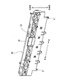
- FIG. 4 is a perspective view of the opening/closing cover 20 viewed from the back side.
- the opening/closing cover 20 is made of a rectangular plate-shaped resin member elongated in the left-right direction.
- U-shaped engaging fulcrum portions 21 opening downward are formed at both ends in the left-right direction of the base edge of the opening/closing cover 20 .
- the left and right engagement fulcrum portions 21 are engaged with left and right support shaft portions provided on the image forming apparatus main body 2, respectively.
- Each support shaft extends horizontally in the left-right direction, and the opening/closing cover 20 is configured to be able to open and close the front side of the accommodation space by rotating about the left and right support shafts as fulcrums.
- the side of the opening/closing cover 20 on which the left and right engagement fulcrum portions 21 are provided is defined as the base end side, and the side opposite to the base end side is defined as the tip end side.
- a manual operation lever 35 (an example of a manual operation portion) is provided in a concave portion 22 provided in the center portion in the left-right direction of the device outer side surface of the opening/closing cover 20 .
- the manual operation lever 35 passes through the opening/closing cover 20 and is connected to the shaft member 31 of the lock mechanism 30 described later so as to rotate integrally.
- a pair of both end vertical ribs 24 and a plurality of intermediate vertical ribs 25 are provided on the tip end side edge (edge opposite to the base end side) of the inner side surface of the opening/closing cover 20 . and are formed.
- a pair of vertical ribs 24 are provided at both ends in the left-right direction of the edge of the opening/closing cover 20 on the leading end side.
- a plurality of intermediate vertical ribs 25 are provided between a pair of both end vertical ribs 24 and are spaced apart in the left-right direction.
- the end vertical ribs 24 and the plurality of intermediate vertical ribs 25 are, as shown in FIG. is set between
- both end vertical ribs 24 and the intermediate vertical rib 25 are formed with U-shaped bearing recesses 24a and 25a that open toward the inside of the device.
- spring fitting recesses 26 are formed outside the pair of vertical ribs 24 in the left-right direction, in which torsion coil springs 34 of the lock mechanism 30, which will be described later, are fitted.
- the spring fitting recess 26 is a U-shaped recess that is formed coaxially with the bearing recesses 24a and 25a and opens toward the inside of the device.
- FIG. Each figure shows a state in which the opening/closing cover 20 is in the closed position.
- the opening/closing cover 20 is assumed to be in the closed position.
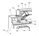
- the lock mechanism 30 includes a shaft member 31 attached to the edge of the front end of the opening/closing cover 20 , left and right hook members 32 fixed to the shaft member 31 so as to rotate integrally, and hook members 32 attached around the shaft member 31 . It has left and right torsion coil springs 34 for biasing.
- Each hook member 32 is inclined downward toward the rear side when viewed from the axial direction of the shaft member 31 .
- Each hook member 32 has a shape in which the distal end portion is pointed at an acute angle when viewed from the axial direction of the shaft member 31 .
- At the rear end of the upper end surface of the hook member 32 there is formed an inclined surface portion 32a inclined downward toward the rear side.
- a V-shaped engaging recess 32b recessed rearward is formed in the upper end portion of the front end face of the hook member 32 .
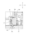
- Each hook member 32 is always biased upward (counterclockwise direction in FIG. 9) around the shaft member 31 by a torsion coil spring 34 .
- the hook member 32 is returned to its original position by the biasing force of the torsion coil spring 34 .
- the engaging recess 32b (engaging hook portion) of the hook member 32 is engaged with the engaged shaft portion 33 (engaged portion), and the opening/closing cover 20 is locked so that it cannot be opened.
- the manual operation lever 35 (see FIG. 3) provided on the opening/closing cover 20 is pulled forward.
- the shaft member 31 connected to the manual operation lever 35 rotates clockwise in FIG. 9, and the engagement between the hook member 32 and the engaged shaft portion 33 is released.
- the shaft member 31 is arranged so as to fit into the bearing recesses 24 a of the both end vertical ribs 24 and the bearing recesses 25 a of the intermediate vertical rib 25 . Both ends of the shaft member 31 protrude outward in the left-right direction from the both-end vertical ribs 24 and are supported by being internally fitted (inserted) into the left and right torsion coil springs 34 .
- the left and right torsion coil springs 34 function as bearing members that support both ends of the shaft member 31 .
- the torsion coil spring 34 has a spring body portion 34a, a first straight portion 34b, a second straight portion 34c, a fixing bending portion 34d, a hook member engaging portion 34e, and a guide groove engaging portion 34f.
- the spring body portion 34a is a spiral portion that generates a restoring force in the twisting direction, and has a substantially cylindrical shape in appearance.
- the spring main body portion 34 a is arranged such that the outer peripheral surface of the spring main body portion 34 a is in close contact with the inner peripheral surface of the spring fitting recess 26 .
- the first linear portion 34b and the second linear portion 34c extend in the tangential direction of the spring body portion 34a from both ends of the spring body portion 34a.
- the first linear portion 34b extends rearward from the lower end portion of the spring body portion 34a when viewed from the axial direction of the spring body portion 34a.
- the second linear portion 34c extends rearward from the upper end portion of the spring body portion 34a when viewed from the axial direction of the spring body portion 34a.
- the fixing bent portion 34d is connected to the tip of the first straight portion 34b and bent downward (an example of a direction orthogonal to the axial direction of the shaft member 31). As shown in FIG. 9, the fixing bent portion 34d abuts on the rear side wall surface of the engaging recess 27a (an example of the portion to be fixed) formed in the lateral rib 27. As shown in FIG. As a result, the spring main body portion 34a of the torsion coil spring 34 is given a reaction force directed to the front side via the fixing bent portion 34d.
- the hook member engaging portion 34e is connected to the tip portion of the second straight portion 34c and is bent so as to surround the hook member 32. As shown in FIG. The hook member engaging portion 34e is in contact with the hook member 32 from below. As a result, the hook member 32 is constantly urged upward by the torsion coil spring 34 .
- the guide groove engaging portion 34f extends along the axial direction (horizontal direction) of the shaft member 31 from the end portion of the hook member engaging portion 34e.
- the tip of the guide groove engaging portion 34f passes through the guide groove 24b (see FIG. 7) formed in the both end vertical ribs 24.
- the guide groove 24b guides the guide groove engaging portion 34f so as to move in an arc in conjunction with the swinging motion of the hook member 32.
- the torsion coil spring 34 engages with the hook member 32 while being fitted in the spring fitting recess 26 to lock the hook member 32 around the axis of the shaft member 31 . While urging it to the side, it functions as a bearing member by rotatably supporting both ends of the shaft member 31 on the inner side surface of the coil.
- the torsion coil spring 34 for biasing the hook member 32 toward the lock side is also used as a bearing member for supporting the shaft member 31, so the number of parts can be reduced and the product cost can be reduced.
- the torsion coil spring 34 is connected to the spiral spring body portion 34a, the first straight portion 34b and the second straight portion 34c extending in the tangential direction from both ends of the spring body portion 34a, and the first straight portion 34b. It is bent in a direction perpendicular to the axial direction of the spring main body portion 34a and has a fixing bent portion 34d that is engaged and fixed to the engagement concave portion 27a.
- the torsion coil spring 34 is configured such that the spring main body 34a is pushed into the spring fitting recess 26 by a reaction force that the fixing bent portion 34d receives from the wall surface of the engagement recess 27a.
- the torsion coil spring 34 can be firmly fixed to the spring fitting recess 26 . As a result, the torsion coil spring 34 can be prevented from coming off or rattling due to the rotation of the shaft member 31 .
- the opening/closing cover 20 has the arc-shaped guide groove 24b that guides the other end (the guide groove engaging portion 34f) of the torsion coil spring 34 that moves in conjunction with the swinging motion of the hook member 32. is doing.
- lock mechanism 30 is applied to the image forming apparatus 1 in the above embodiment, the present invention is not limited to such an embodiment.
- the lock mechanism 30 may be applied to any device as long as it has the opening/closing cover 20 .
- the present invention is useful for a lock mechanism and an image forming apparatus provided with a lock mechanism, and is particularly useful when applied to a printer, facsimile machine, copier, multifunction peripheral (MFP), or the like.
- MFP multifunction peripheral
Landscapes
- Physics & Mathematics (AREA)
- General Physics & Mathematics (AREA)
- Engineering & Computer Science (AREA)
- Mechanical Engineering (AREA)
- Electrophotography Configuration And Component (AREA)
- Accessory Devices And Overall Control Thereof (AREA)
Abstract
Description
画像形成装置1は、画像形成装置本体2と本体2の上側に配置された画像読取部3とを備えている。画像形成装置本体2は、本体2の上下方向中間部に配置された印刷部4と、印刷部4の下側に配置された給紙カセット5とを有している。給紙カセット5内には用紙が収容されている。印刷部4(画像形成部)は、給紙カセット5から供給される記録媒体としての用紙に対して所定の画像データに基づいて印刷(画像形成)を行なう。印刷部4における印刷方式には例えば電子写真方式が採用されている。すなわち、印刷部4は、イエロ-、シアン、マゼンタ、及びブラックの各色に対応する四つの感光体ドラムユニットを有している。各感光体ドラムユニットでは、感光体ドラムの表面に画像データに対応するレーザー光を照射して静電潜像を形成し、当該静電潜像を各色のトナーで現像する。現像された各色のトナー像は、中間転写ベルトの表面に一次転写され重畳された後、給紙カセット5から供給される用紙に二次転写される。
図3は、開閉カバー20を表側から見た斜視図であり、図4は開閉カバー20を裏側から見た斜視図である。開閉カバー20は、左右方向に長い矩形板状の樹脂部材から構成される。開閉カバー20の基端縁における左右方向の両端部には、下側に開放するU字状の係合支点部21が形成されている。左右の係合支点部21は、それぞれ、画像形成装置本体2に設けられた左右の支持軸部に係合する。各支持軸部は左右方向に水平に延びており、開閉カバー20は左右の支持軸部を支点に回動することで、上記収容空間の前側を開閉可能に構成されている。以下の説明では、開閉カバー20における左右の係合支点部21が設けられる側を基端側と定義し、基端側とは反対側を先端側と定義する。
次に、図7乃至図10を参照して、ロック機構30の詳細を説明する。各図はいずれも、開閉カバー20が閉位置にある状態を示している。以下、特に断らない限り、開閉カバー20が閉位置にある状態として説明を行なう。
軸部材31は、両端縦リブ24の軸受凹部24a及び中間縦リブ25の軸受凹部25aに嵌合して配置されている。軸部材31の両端部は、両端縦リブ24よりも左右方向の外側に突出していて、左右の捻りコイルバネ34に内嵌(内挿)して支持されている。左右の捻りコイルバネ34は、軸部材31の両端部を支持する軸受部材として機能する。
以上説明したように、上記実施形態では、捻りコイルバネ34は、バネ嵌合凹部26に嵌合された状態で、フック部材32に係合することによりフック部材32を軸部材31の軸線回りにロック側に付勢するとともに、軸部材31の両端部をコイル内側面に回動可能に支持して軸受部材として機能する。
上記実施形態では、ロック機構30を画像形成装置1に適用したが、本発明はそのような実施形態に限定されない。ロック機構30は、開閉カバー20を有する装置であれば如何なる装置に適用してもよい。
Claims (5)
- 一端縁を支点として回動することで開閉可能なカバー部材と、
前記カバー部材の前記一端縁に対向する他端縁に沿って延びるとともに、両端部が前記カバー部材に回動可能に支持される軸部材と、
前記軸部材に回転一体に連結され、先端部に係合フック部が形成されたフック部材と、
前記カバー部材が閉位置に移動したときに前記フック部材の前記係合フック部に係合することで前記カバー部材をロックする被係合部と、
前記フック部材を、前記係合フック部が前記被係合部に係合する側であるロック側に付勢する捻りコイルバネと、
前記カバー部材が前記閉位置にある状態で、手動操作されることにより前記軸部材を回転させて前記係合フック部と前記被係合部との係合を解除する手動操作部とを備え、
前記カバー部材は、
前記軸部材の軸線に直交する方向の一方側に開放し、前記捻りコイルバネを前記一方側から受入れるとともに前記捻りコイルバネの外周面に嵌合する嵌合凹部と、
前記捻りコイルバネの一端部が固定される被固定部とを備え、
前記捻りコイルバネは、前記嵌合凹部に嵌合された状態で、前記フック部材に係合することにより前記フック部材を前記軸部材の軸線回りにロック側に付勢するとともに、前記軸部材の両端部をコイル内側面に回動可能に支持する、ロック機構。 - 前記カバー部材は、前記被固定部として係合凹部を有し、
前記捻りコイルバネは、螺旋状のバネ本体部と、前記バネ本体部の両端部から接線方向に延びる第一直線部及び第二直線部と、前記第一直線部に接続され、前記バネ本体部の軸線方向に直交する方向に屈曲するとともに、前記係合凹部に係合固定される固定用屈曲部とを有し、前記固定用屈曲部が前記係合凹部の壁面より受ける反力によって前記バネ本体部を前記嵌合凹部に押し込むように構成されている、請求項1に記載のロック機構。 - 前記カバー部材は、前記フック部材の揺動動作に連動して移動する前記捻りコイルバネの他端部をガイドする円弧状の溝部を更に有している、請求項2に記載のロック機構。
- 前記捻りコイルバネは、前記第二直線部の先端部に接続されて前記フック部材を囲むように屈曲形成されているフック部材係合部を更に備え、前記フック部材係合部は、前記フック部材に当接している、請求項2に記載のロック機構。
- 請求項1に記載のロック機構と、
前記被係合部が設けられる本体と、
画像を記録媒体に形成する画像形成部と、を備える画像形成装置。
Priority Applications (3)
| Application Number | Priority Date | Filing Date | Title |
|---|---|---|---|
| JP2023508780A JP7593478B2 (ja) | 2021-03-24 | 2022-02-16 | ロック機構、及びロック機構を備える画像形成装置 |
| US18/282,047 US12197163B2 (en) | 2021-03-24 | 2022-02-16 | Locking mechanism and image forming apparatus equipped with locking mechanism |
| CN202280023107.0A CN117063130A (zh) | 2021-03-24 | 2022-02-16 | 锁定机构及具备锁定机构的图像形成装置 |
Applications Claiming Priority (2)
| Application Number | Priority Date | Filing Date | Title |
|---|---|---|---|
| JP2021-050282 | 2021-03-24 | ||
| JP2021050282 | 2021-03-24 |
Publications (1)
| Publication Number | Publication Date |
|---|---|
| WO2022201982A1 true WO2022201982A1 (ja) | 2022-09-29 |
Family
ID=83396878
Family Applications (1)
| Application Number | Title | Priority Date | Filing Date |
|---|---|---|---|
| PCT/JP2022/006115 Ceased WO2022201982A1 (ja) | 2021-03-24 | 2022-02-16 | ロック機構、及びロック機構を備える画像形成装置 |
Country Status (4)
| Country | Link |
|---|---|
| US (1) | US12197163B2 (ja) |
| JP (1) | JP7593478B2 (ja) |
| CN (1) | CN117063130A (ja) |
| WO (1) | WO2022201982A1 (ja) |
Cited By (1)
| Publication number | Priority date | Publication date | Assignee | Title |
|---|---|---|---|---|
| US12386287B2 (en) | 2023-08-23 | 2025-08-12 | Kyocera Document Solutions Inc. | Unit locating mechanism and image forming apparatus |
Citations (10)
| Publication number | Priority date | Publication date | Assignee | Title |
|---|---|---|---|---|
| JP2005164732A (ja) * | 2003-11-28 | 2005-06-23 | Canon Inc | 画像形成装置 |
| US20070212107A1 (en) * | 2006-03-08 | 2007-09-13 | Xerox Corporation | Gang safety latching mechanism and an image producing machine including same |
| JP2009139903A (ja) * | 2007-01-30 | 2009-06-25 | Ricoh Co Ltd | 画像形成装置 |
| JP2011053333A (ja) * | 2009-08-31 | 2011-03-17 | Fuji Xerox Co Ltd | 開閉機構および画像形成装置 |
| JP2013249677A (ja) * | 2012-06-01 | 2013-12-12 | Toyo Seat Co Ltd | ルーフ部材の固定装置 |
| JP2014010298A (ja) * | 2012-06-29 | 2014-01-20 | Kyocera Document Solutions Inc | 開閉カバーロック機構及び画像形成装置 |
| JP2014015025A (ja) * | 2012-07-11 | 2014-01-30 | Kyocera Document Solutions Inc | 開閉カバーロック機構及び画像形成装置 |
| JP2017043464A (ja) * | 2015-08-27 | 2017-03-02 | 京セラドキュメントソリューションズ株式会社 | 画像形成装置 |
| JP2017151314A (ja) * | 2016-02-25 | 2017-08-31 | キヤノンファインテック株式会社 | 扉閉動作装置と画像形成装置 |
| JP2019034805A (ja) * | 2017-08-10 | 2019-03-07 | 富士ゼロックス株式会社 | 用紙搬送装置及び画像形成装置 |
Family Cites Families (10)
| Publication number | Priority date | Publication date | Assignee | Title |
|---|---|---|---|---|
| JP2004138775A (ja) * | 2002-10-17 | 2004-05-13 | Ricoh Co Ltd | 画像形成装置 |
| KR200306485Y1 (ko) * | 2002-12-11 | 2003-03-08 | 한국후지제록스 주식회사 | 화상형성기의 용지이송부 래치장치 |
| JP4952113B2 (ja) * | 2006-07-26 | 2012-06-13 | ブラザー工業株式会社 | 画像形成装置 |
| JP4905345B2 (ja) * | 2007-12-27 | 2012-03-28 | ブラザー工業株式会社 | 画像形成装置 |
| JP2010127997A (ja) | 2008-11-25 | 2010-06-10 | Kyocera Mita Corp | 画像形成装置 |
| US20110215596A1 (en) * | 2010-03-03 | 2011-09-08 | Decrane Aerospace, Inc. | Cabinet latch |
| JP5625686B2 (ja) * | 2010-09-28 | 2014-11-19 | ブラザー工業株式会社 | 画像形成装置 |
| JP2014030024A (ja) * | 2013-08-22 | 2014-02-13 | Oki Data Corp | 開閉カバーロック機構及びそれを備えた画像形成装置 |
| JP7062895B2 (ja) * | 2017-08-28 | 2022-05-09 | 京セラドキュメントソリューションズ株式会社 | 可動ユニットのロック機構及びそれを備えたシート給送装置並びに画像形成装置 |
| US10656590B2 (en) * | 2018-02-27 | 2020-05-19 | Canon Kabushiki Kaisha | Locking mechanism and image forming apparatus |
-
2022
- 2022-02-16 WO PCT/JP2022/006115 patent/WO2022201982A1/ja not_active Ceased
- 2022-02-16 CN CN202280023107.0A patent/CN117063130A/zh active Pending
- 2022-02-16 JP JP2023508780A patent/JP7593478B2/ja active Active
- 2022-02-16 US US18/282,047 patent/US12197163B2/en active Active
Patent Citations (10)
| Publication number | Priority date | Publication date | Assignee | Title |
|---|---|---|---|---|
| JP2005164732A (ja) * | 2003-11-28 | 2005-06-23 | Canon Inc | 画像形成装置 |
| US20070212107A1 (en) * | 2006-03-08 | 2007-09-13 | Xerox Corporation | Gang safety latching mechanism and an image producing machine including same |
| JP2009139903A (ja) * | 2007-01-30 | 2009-06-25 | Ricoh Co Ltd | 画像形成装置 |
| JP2011053333A (ja) * | 2009-08-31 | 2011-03-17 | Fuji Xerox Co Ltd | 開閉機構および画像形成装置 |
| JP2013249677A (ja) * | 2012-06-01 | 2013-12-12 | Toyo Seat Co Ltd | ルーフ部材の固定装置 |
| JP2014010298A (ja) * | 2012-06-29 | 2014-01-20 | Kyocera Document Solutions Inc | 開閉カバーロック機構及び画像形成装置 |
| JP2014015025A (ja) * | 2012-07-11 | 2014-01-30 | Kyocera Document Solutions Inc | 開閉カバーロック機構及び画像形成装置 |
| JP2017043464A (ja) * | 2015-08-27 | 2017-03-02 | 京セラドキュメントソリューションズ株式会社 | 画像形成装置 |
| JP2017151314A (ja) * | 2016-02-25 | 2017-08-31 | キヤノンファインテック株式会社 | 扉閉動作装置と画像形成装置 |
| JP2019034805A (ja) * | 2017-08-10 | 2019-03-07 | 富士ゼロックス株式会社 | 用紙搬送装置及び画像形成装置 |
Cited By (1)
| Publication number | Priority date | Publication date | Assignee | Title |
|---|---|---|---|---|
| US12386287B2 (en) | 2023-08-23 | 2025-08-12 | Kyocera Document Solutions Inc. | Unit locating mechanism and image forming apparatus |
Also Published As
| Publication number | Publication date |
|---|---|
| CN117063130A (zh) | 2023-11-14 |
| JPWO2022201982A1 (ja) | 2022-09-29 |
| US20240167304A1 (en) | 2024-05-23 |
| US12197163B2 (en) | 2025-01-14 |
| JP7593478B2 (ja) | 2024-12-03 |
Similar Documents
| Publication | Publication Date | Title |
|---|---|---|
| JP5168647B2 (ja) | 引き込み装置および画像形成装置 | |
| JP5551102B2 (ja) | 画像形成装置 | |
| CN101819399B (zh) | 可移除部件的保持装置及图像形成装置 | |
| JP4977630B2 (ja) | 画像形成装置 | |
| US9242819B2 (en) | Sheet conveyance apparatus ensuring reduced damage of stopper | |
| JP2006118613A (ja) | ヒンジ装置、そのヒンジ装置を備えた自動原稿搬送装置、読取ユニット及び画像形成装置 | |
| EP2690504A1 (en) | Sheet feeding device, and image forming apparatus provided with same | |
| JP2011203441A (ja) | トナー補給装置及びこれを搭載した画像形成装置 | |
| JP2009300930A (ja) | 画像形成装置 | |
| CN112015064B (zh) | 图像形成装置 | |
| CN112015063B (zh) | 图像形成装置 | |
| CN104076641B (zh) | 图像形成装置 | |
| JP5217717B2 (ja) | 画像形成装置 | |
| JP7593478B2 (ja) | ロック機構、及びロック機構を備える画像形成装置 | |
| JP4389734B2 (ja) | 画像形成装置 | |
| JP2006157279A (ja) | 原稿読取装置及びそれを備えた画像形成装置 | |
| JP3982986B2 (ja) | 画像形成装置 | |
| JP2008162087A (ja) | 画像形成装置 | |
| JP4131331B2 (ja) | 画像形成装置 | |
| JP5463615B2 (ja) | 画像形成装置 | |
| JP4967549B2 (ja) | 画像形成装置 | |
| JP6583571B2 (ja) | 画像形成装置 | |
| JP6201625B2 (ja) | 用紙搬送装置、原稿読取装置、及び画像形成装置 | |
| JP2024140149A (ja) | 画像形成装置 | |
| JP2010061062A (ja) | 係止機構、および、それを備えた画像処理装置 |
Legal Events
| Date | Code | Title | Description |
|---|---|---|---|
| 121 | Ep: the epo has been informed by wipo that ep was designated in this application |
Ref document number: 22774782 Country of ref document: EP Kind code of ref document: A1 |
|
| WWE | Wipo information: entry into national phase |
Ref document number: 2023508780 Country of ref document: JP |
|
| WWE | Wipo information: entry into national phase |
Ref document number: 18282047 Country of ref document: US |
|
| WWE | Wipo information: entry into national phase |
Ref document number: 202280023107.0 Country of ref document: CN |
|
| NENP | Non-entry into the national phase |
Ref country code: DE |
|
| 122 | Ep: pct application non-entry in european phase |
Ref document number: 22774782 Country of ref document: EP Kind code of ref document: A1 |