WO2022201864A1 - 鞍乗り型車両 - Google Patents
鞍乗り型車両 Download PDFInfo
- Publication number
- WO2022201864A1 WO2022201864A1 PCT/JP2022/003612 JP2022003612W WO2022201864A1 WO 2022201864 A1 WO2022201864 A1 WO 2022201864A1 JP 2022003612 W JP2022003612 W JP 2022003612W WO 2022201864 A1 WO2022201864 A1 WO 2022201864A1
- Authority
- WO
- WIPO (PCT)
- Prior art keywords
- type vehicle
- straddle
- vibrator
- vehicle
- saddle
- Prior art date
- Legal status (The legal status is an assumption and is not a legal conclusion. Google has not performed a legal analysis and makes no representation as to the accuracy of the status listed.)
- Ceased
Links
Images




Classifications
-
- B—PERFORMING OPERATIONS; TRANSPORTING
- B60—VEHICLES IN GENERAL
- B60R—VEHICLES, VEHICLE FITTINGS, OR VEHICLE PARTS, NOT OTHERWISE PROVIDED FOR
- B60R21/00—Arrangements or fittings on vehicles for protecting or preventing injuries to occupants or pedestrians in case of accidents or other traffic risks
- B60R21/01—Electrical circuits for triggering passive safety arrangements, e.g. airbags, safety belt tighteners, in case of vehicle accidents or impending vehicle accidents
- B60R21/013—Electrical circuits for triggering passive safety arrangements, e.g. airbags, safety belt tighteners, in case of vehicle accidents or impending vehicle accidents including means for detecting collisions, impending collisions or roll-over
- B60R21/0134—Electrical circuits for triggering passive safety arrangements, e.g. airbags, safety belt tighteners, in case of vehicle accidents or impending vehicle accidents including means for detecting collisions, impending collisions or roll-over responsive to imminent contact with an obstacle, e.g. using radar systems
-
- B—PERFORMING OPERATIONS; TRANSPORTING
- B62—LAND VEHICLES FOR TRAVELLING OTHERWISE THAN ON RAILS
- B62J—CYCLE SADDLES OR SEATS; AUXILIARY DEVICES OR ACCESSORIES SPECIALLY ADAPTED TO CYCLES AND NOT OTHERWISE PROVIDED FOR, e.g. ARTICLE CARRIERS OR CYCLE PROTECTORS
- B62J45/00—Electrical equipment arrangements specially adapted for use as accessories on cycles, not otherwise provided for
- B62J45/40—Sensor arrangements; Mounting thereof
-
- B—PERFORMING OPERATIONS; TRANSPORTING
- B62—LAND VEHICLES FOR TRAVELLING OTHERWISE THAN ON RAILS
- B62J—CYCLE SADDLES OR SEATS; AUXILIARY DEVICES OR ACCESSORIES SPECIALLY ADAPTED TO CYCLES AND NOT OTHERWISE PROVIDED FOR, e.g. ARTICLE CARRIERS OR CYCLE PROTECTORS
- B62J50/00—Arrangements specially adapted for use on cycles not provided for in main groups B62J1/00 - B62J45/00
- B62J50/20—Information-providing devices
- B62J50/21—Information-providing devices intended to provide information to rider or passenger
Definitions
- the present invention relates to a saddle-ride type vehicle.
- the direction information notification device described in Patent Document 1 uses sound and vibration to notify the driver of the motorcycle of the presence and direction of approach of an obstacle approaching the motorcycle.
- This direction information notification device includes headphones and a number of vibrators, and the headphones and a number of vibrators are provided on a helmet worn by the driver.
- the emergency vehicle notification device described in Patent Document 2 uses vibration to notify the driver of a general vehicle of the presence and traveling direction of an approaching emergency vehicle.
- This emergency vehicle notification device includes a large number of vibrating sections such as a speaker and an exciter, and the large number of vibrating sections are provided dispersedly in the seat cushion, seat back, and headrest of the driver's seat.
- the direction information notification device described in Patent Document 1 has eight devices arranged at intervals in the circumferential direction of the driver's head in order to notify the driver of the approach direction of an obstacle approaching the motorcycle. vibrator.
- the use of multiple vibrators increases costs and also increases the load on the driver's head.
- the emergency vehicle notification device described in Patent Document 2 also uses a large number of vibrating units, increasing the cost.
- many vibrating units are provided in a distributed manner on the seat cushion, seat back, and headrest of the driver's seat. Applying an emergency vehicle notification device is difficult.
- the present invention proposes a straddle-type vehicle that allows the driver to recognize the approach of an object and the direction of approach.
- a saddle-ride type vehicle includes a plurality of tactile devices capable of stimulating the tactile sense of the driver of the saddle-ride type vehicle, a detection unit for detecting the approach of an object to the saddle-ride type vehicle and the direction of approach, and a detection result of the sensor. and a control unit for controlling the plurality of haptic devices, the plurality of haptic devices being arranged in front of the vehicle relative to the first haptic device and the first haptic device, and passing through the first haptic device in the vehicle longitudinal direction.
- a second left haptic device and a second right haptic device are respectively arranged on one side and the other side in the vehicle width direction with respect to the extending center line; a third left haptic device and a third right haptic device positioned between the right haptic device and positioned on the one side and the other side, respectively, with respect to the centerline.
- the driver can be made to recognize the approach and approach direction of the object.
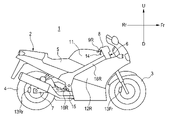
- FIG. 1 is a side view showing the left side of a straddle-type vehicle according to one embodiment of the present invention
- FIG. FIG. 2 is a side view showing the right side of the saddle-ride type vehicle in FIG. 1
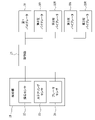
- FIG. 2 is a functional block diagram of the saddle-ride type vehicle of FIG. 1
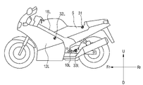
- FIG. 2 is a side view showing an example arrangement of a plurality of tactile devices in the straddle-type vehicle of FIG. 1
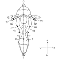
- FIG. 2 is a plan view showing an arrangement example of a plurality of haptic devices in the straddle-type vehicle of FIG. 1
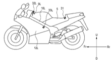
- FIG. 2 is a side view showing another arrangement example of a plurality of tactile devices in the straddle-type vehicle of FIG. 1
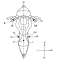
- FIG. 2 is a plan view showing another arrangement example of a plurality of tactile devices in the straddle-type vehicle of FIG. 1;
- FIG. 3 is a side view showing still another arrangement example of a plurality of tactile devices in the straddle-type vehicle of FIG. 1;
- FIG. 2 is a plan view showing still another arrangement example of a plurality of tactile devices in the saddle-ride type vehicle of FIG. 1;
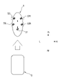
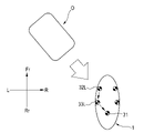
- the schematic diagram which shows an example of a tactile stimulation pattern.
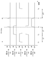
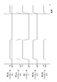
- FIG. 11 is a timing chart showing operating states of a plurality of tactile devices in the tactile stimulation pattern of FIG. 10;
- FIG. 4 is a schematic diagram showing another example of a tactile stimulation pattern;
- FIG. 4 is a schematic diagram showing another example of a tactile stimulation pattern;
- FIG. 4 is a schematic diagram showing another example of a tactile stimulation pattern;
- FIG. 4 is a schematic diagram showing another example of a tactile stimulation pattern;
- FIG. 4 is a schematic diagram showing another example of a tactile stimulation pattern;
- FIG. 4 is a schematic diagram showing another example of a tactile stimulation pattern;
- FIG. 4 is a schematic diagram showing another example of a tactile stimulation pattern;
- FIG. 4 is a schematic diagram showing another example of a tactile stimulation pattern;
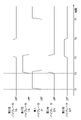
- 4 is a timing chart showing operating states of a plurality of tactile devices in another example of tactile stimulation patterns.
- 4 is a timing chart showing operating states of a plurality of tactile devices in another example of tactile stimulation patterns.
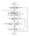
- 2 is a flowchart showing processing performed by a detection unit and a control unit of the saddle-riding type vehicle shown in FIG. 1;
- FIG. 21 is a flowchart showing a modification of the process of FIG. 20;
- FIGS 1 and 2 show a saddle-riding vehicle that is an embodiment of the present invention.
- the drawings are viewed in the direction of the reference numerals, and the front of the saddle type vehicle is indicated by Fr, the rear by Rr, the upper by U, the lower by D, the left by L, and the right by R.
- a straddle-type vehicle 1 (hereinafter also simply referred to as "vehicle 1") is a motorcycle and includes a vehicle body 2 including front wheels 3 and rear wheels 4, and a power train including an engine.
- the power train drives the rear wheels 4 by transmitting power generated by the engine to the rear wheels 4 which are driving wheels.
- the vehicle body 2 includes a frame constituting the skeleton of the vehicle body 2, a driver's seat 5 installed on the upper part of the frame, a steering wheel 6 connected to the front part of the frame, and a swing arm 7 connected to the lower part of the frame.
- a steering wheel 6 supports the front wheels 3 and a swing arm 7 supports the rear wheels 4 .
- the steering 6 includes a handle 8 for steering operation, and the handle 8 is provided with a left handle grip 9L and a right handle grip 9R that are gripped by the driver.
- a left step 10L and a right step 10R on which the driver's feet are placed are provided at the bottom of the frame.
- the left step 10L and the right step 10R are arranged in front of the driver's seat 5 in the vehicle.
- a fuel tank 11 is installed between the driver's seat 5 and the steering wheel 6 in the longitudinal direction of the vehicle.
- An engine is installed below the fuel tank 11, and devices such as a battery, an injector, or a carburetor are provided between the fuel tank 11 and the engine.
- the vehicle body 2 further includes a left side cover 12L and a right side cover 12R that protect these devices.
- the left side cover 12L and the right side cover 12R are arranged between the left handlebar grip 9L and the right handlebar grip 9R and the left step 10L and the right step 10R in the longitudinal direction of the vehicle. It is arranged between the step 10L and the right step 10R and constitutes the outer surfaces of the left and right sides of the vehicle body 2 .
- the vehicle body 2 further includes a front brake 13Fr for braking the front wheels 3 and a rear brake 13Rr for braking the rear wheels 4.
- the front brake 13Fr is operated by a brake lever 14 provided on the right handle grip 9R.
- the rear brake 13Rr is operated by a brake pedal 15 provided on the right step 10R.
- a brake lever for operating the rear brake 13Rr may be provided on the left handle grip 9L.
- Fig. 3 shows the functional blocks of the vehicle 1.
- the vehicle 1 notifies the driver of the vehicle 1 of the existence and approaching direction of an object approaching the vehicle 1 by stimulating the driver's sense of touch.
- the object is for example another vehicle.
- the vehicle 1 includes a plurality of tactile devices capable of stimulating the tactile sensation of the driver, a detection unit 20 for detecting the presence and approaching direction of an object approaching the vehicle 1, and a control unit 21.
- the vehicle 1 includes a first vibrator 31, a second left vibrator 32L and a second right vibrator 32R, and a third left vibrator 33L and a third right vibrator 33R as a plurality of haptic devices.
- the first vibrator 31, the second left vibrator 32L, the second right vibrator 32R, the third left vibrator 33L, and the third right vibrator 33R can stimulate the driver's sense of touch with vibration.
- the detection unit 20 has a proximity sensor 22 that measures the distance between the vehicle 1 and the object and the direction of the object with the vehicle 1 as the base point.
- Examples of the proximity sensor 22 include radar using millimeter waves and microwaves, and LiDAR (light detection and ranging), which is a sensor using laser light.
- the detection unit 20 detects the existence and approach direction of an object approaching the vehicle 1 based on the measurement result of the proximity sensor 22 .
- the detection unit 20 can identify the approaching direction of the object at least in a total of 8 directions: forward, backward, leftward, rightward, obliquely forward left, obliquely forward right, obliquely backward left, and obliquely backward right.
- the detection unit 20 can detect an object avoidance operation in the vehicle 1 based on at least one of the distance between the vehicle and the object and the relative speed of the vehicle with respect to the object in the traveling direction of the vehicle 1. . Distance and relative velocity are measured by proximity sensor 22 . Furthermore, in the vehicle 1, the detection unit 20 has a steering sensor 23 for detecting rotation of the steering wheel 6, and a brake sensor 24 for detecting operation of at least one of the front brake 13Fr and the rear brake 13Rr. Based on at least one of the detection result of 23 and the detection result of the brake sensor 24, the object avoidance operation of the vehicle 1 can be detected.
- the control unit 21 controls the first vibrator 31, the second left vibrator 32L, the second right vibrator 32R, the third left vibrator 33L, and the third right vibrator 33R according to the detection result of the detection unit 20.
- the control of the third right vibrator 33R is realized by the processor operating according to a predetermined program.
- Figures 4 and 5 show examples of installation of multiple haptic devices.
- the second left vibrator 32L and the second right vibrator 32R are installed in front of the vehicle from the first vibrator 31. Further, the second left vibrator 32L is installed on one side in the vehicle width direction, and the second right vibrator 32R is installed on the other side with respect to the center line CL extending in the vehicle front-rear direction through the first vibrator 31 .
- the third left vibrator 33L and the third right vibrator 33R are installed between the first vibrator 31 and the second left vibrator 32L and the second right vibrator 32R in the longitudinal direction of the vehicle. Furthermore, the third left vibrator 33L is installed on one side in the vehicle width direction, and the third right vibrator 33R is installed on the other side of the center line CL extending in the vehicle longitudinal direction through the first vibrator 31 .
- the first vibrator 31, the second left vibrator 32L, the second right vibrator 32R, the third left vibrator 33L, and the third right vibrator 33R are installed at locations in the vehicle 1 where they can come into contact with the body of the driver.
- the first vibrator 31 is installed in the driver's seat 5 and can come into contact with the waist or buttocks of the driver.
- the second left vibrator 32L and the second right vibrator 32R are installed on the left side cover 12L and the right side cover 12R, and can come into contact with the left and right thighs, knees, or calves of the driver.
- the third left vibrator 33L and the third right vibrator 33R are installed on the left step 10L and the right step 10R, and can come into contact with the left and right feet of the driver.
- the second left vibrator 32L and the second right vibrator 32R may be installed on the left side 16L and right side 16R of the front portion of the frame exposed above the left side cover 12L and the right side cover 12R.
- the left side 16L and the right side 16R of the front part of the frame are located in front of the driver's seat 5 and above the left step 10L and the right step 10R, and constitute the outer surfaces of the left and right sides of the vehicle body 2. is doing.
- a second left vibrator 32L and a second right vibrator 32R installed on the left side 16L and right side 16R of the front part of the frame can contact the left and right legs (thighs, knees, or calves) of the driver.
- Figures 6 and 7 show other installation examples of a plurality of haptic devices.
- the first vibrator 31 is installed in the driver's seat 5.
- FIG. The second left vibrator 32L and the second right vibrator 32R are installed on the left handle grip 9L and the right handle grip 9R, and can come into contact with the left and right hands of the driver.
- the third left vibrator 33L and the third right vibrator 33R are installed on the left side cover 12L and the right side cover 12R.
- the third left vibrator 33L and the third right vibrator 33R may be installed on the left side 16L and right side 16R of the front portion of the frame.
- Figures 8 and 9 show still another installation example of a plurality of haptic devices.
- the first vibrator 31 is installed in the driver's seat 5, and the second left vibrator 32L and the second right vibrator 32R are installed in the left handle grip 9L and the right handle grip 9R.
- a third left vibrator 33L and a third right vibrator 33R are installed on the left step 10L and the right step 10R.
- the control unit 21 vibrates the vibrator according to the approach direction of the object. to form different tactile stimulation patterns.
- FIG. 10 and 11 show tactile stimulation patterns when an object approaches the vehicle 1 from behind.
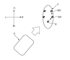
- FIG. 12 shows a tactile stimulation pattern when an object approaches the vehicle 1 from the front.
- FIG. 13 shows a tactile stimulus pattern when an object approaches the vehicle 1 from the left.
- FIG. 14 shows a tactile sense stimulus pattern when an object approaches the vehicle 1 diagonally from the front left.
- FIG. 15 shows a tactile stimulation pattern when an object approaches the vehicle 1 obliquely from the rear left.
- the control unit 21 shifts the activation timings of the first vibrator 31, the second left vibrator 32L, the second right vibrator 32R, the third left vibrator 33L, and the third right vibrator 33R to activate these vibrators. Then, the control unit 21 forms a plurality of tactile stimulation patterns according to the order in which the first vibrator 31, the second left vibrator 32L, the second right vibrator 32R, the third left vibrator 33L, and the third right vibrator 33R are operated.
- the controller 21 operates the first vibrator 31 at the first timing T1, and then at the second timing T2.
- the third left vibrator 33L and the third right vibrator 33R are activated, and finally the second left vibrator 32L and the second right vibrator 32R are activated at the third timing T3.
- a vibrating location that stimulates the driver's tactile sense moves sequentially from the rear of the vehicle near the object O toward the front of the vehicle. The above operation is regarded as one cycle, and the control unit 21 repeats this cycle.
- the control unit 21 first activates the second left vibrator 32L and the second right vibrator 32R at the first timing, and then the second vibrator 32L and the second right vibrator 32R.
- the third left vibrator 33L and the third right vibrator 33R are activated at timing 2, and finally the first vibrator 31 is activated at the third timing.
- the control unit 21 first activates the second left vibrator 32L and the third left vibrator 33L at a first timing, and then activates the second left vibrator 32L and the third left vibrator 33L.
- the first vibrator 31 is activated at the second timing, and finally the second right vibrator 32R and the third right vibrator 33R are activated at the third timing.
- the control unit first operates the second right vibrator 32R and the third right vibrator 33R at the first timing, and then operates the second right vibrator 32R and the third right vibrator 33R.
- the first vibrator 31 is activated at the timing, and finally the second left vibrator 32L and the third left vibrator 33L are activated at the third timing.
- the control unit 21 first operates the second left vibrator 32L and the first vibrator 31 at a first timing, and then operates the second left vibrator 32L and the first vibrator 31.
- the third left vibrator 33L is activated at the second timing, and finally the second right vibrator 32R and the third right vibrator 33R are activated at the third timing.
- the control unit 21 first operates the second right vibrator 32R and the first vibrator 31 at the first timing, and then operates the second vibrator 32R and the first vibrator 31 at the first timing.
- the third right vibrator 33R is activated at the timing of
- the second left vibrator 32L and the third left vibrator 33L are activated at the third timing.
- the control unit 21 first activates the third left vibrator 33L and the first vibrator 31 at a first timing, The second left vibrator 32L is activated at the second timing, and finally the second right vibrator 32R and the third right vibrator 33R are activated at the third timing.
- the control unit 21 first operates the third right vibrator 33R and the first vibrator 31 at the first timing, and then operates the second vibrator.
- the second right vibrator 32R is activated at the timing of
- the second left vibrator 32L and the third left vibrator 33L are activated at the third timing.
- the driver perceives the tactile stimulus pattern, and recognizes the direction corresponding to the perceived tactile stimulus pattern as the approaching direction of the object O.
- the control unit 21 may change the amount of deviation in operation timing and the interval between cycle operations according to the distance between the vehicle 1 and the object O. For example, in the tactile sense stimulus pattern when the object O is approaching from behind the vehicle 1 shown in FIGS. A time interval between the second timing T2 for operating the vibrator 33R and a time interval between the second timing T2 and a third timing T3 for operating the second left vibrator 32L and the second right vibrator 32R. Let the quantity be ⁇ T. Also, the time from the timing T4 at which the second left vibrator 32L and the second right vibrator 32R are stopped to the timing T5 at which the first vibrator 31 is activated in the next cycle is defined as a cycle operation interval ⁇ TT.
- the control unit 21 shortens the operation timing deviation amount ⁇ T and the cycle operation interval ⁇ TT.
- the driver perceives changes in the operation timing deviation amount ⁇ T and the cycle operation interval ⁇ TT, and can recognize the approximate distance between the vehicle 1 and the object O based on the perceived changes.
- control unit 21 controls the first vibrator 31, the second left vibrator 32L, the second right vibrator 32R, the third left vibrator 33L, and the third right vibrator 33R as the distance between the vehicle 1 and the object O decreases.
- the amplitude may be increased and the frequency may be increased.
- the driver can recognize the approximate distance between the vehicle 1 and the object O based on changes in amplitude and frequency.
- the first vibrator 31, the second left vibrator 32L, the second right vibrator 32R, the third left vibrator 33L, and the third right vibrator 33R start from the vibrator closest to the object O, and It operates in order with three different operation timings.
- the driver can intuitively recognize the direction in which the object O is approaching.
- the three actuation timings that are shifted from each other enhance the distinguishability of the approaching direction of the object O.
- the first vibrator 31 is activated at the first timing, and then the second left vibrator 32L and the second right vibrator 32R are activated at the second timing.
- the repetition of this tactile stimulus pattern may make it difficult to determine the vibrator that is the starting point when the deviation amount ⁇ T of the activation timing and the interval ⁇ TT of the cycle operation are short.
- the three operation timings that are shifted from each other make it easy to determine the vibrator that is the starting point, regardless of the amount of shift ⁇ T in the operation timings and the interval ⁇ TT of the cycle operation. Thereby, the identifiability of the approaching direction of the object O is enhanced.
- all vibrators of the first vibrator 31, the second left vibrator 32L, the second right vibrator 32R, the third left vibrator 33L, and the third right vibrator 33R are operated.
- Some of the above vibrators may be activated.
- the first vibrator 31 may be activated at a third timing.
- the object O approaches the vehicle 1 obliquely from the rear left as shown in FIG. 17, first the first vibrator 31 is activated at the first timing, and then the third right vibrator 33R is activated at the second timing. and finally the second right vibrator 32R may be operated at a third timing.
- the tactile sense stimulation patterns that differ according to the approach direction of the object O are caused by the difference in operation timing of the first vibrator 31, the second left vibrator 32L, the second right vibrator 32R, the third left vibrator 33L, and the third right vibrator 33R.
- it may be formed by the difference in stimulation intensity of each of these vibrators.
- the stimulation intensity of the vibrator that stimulates the driver's tactile sense by vibration is represented by the amplitude of the vibration.
- FIG. 18 shows a tactile stimulation pattern when an object approaches the vehicle 1 from behind.
- the control unit 21 simultaneously activates the first vibrator 31, the second left vibrator 32L, the second right vibrator 32R, the third left vibrator 33L, and the third right vibrator 33R.
- the control unit 21 determines that the amplitude A1 of the first vibrator 31 closest to the object O is the largest (the stimulation intensity is the highest), and the amplitude A2 of the second left vibrator 32L and the second right vibrator 32R farthest from the object O is
- the first vibrator 31, the second left vibrator 32L, the second right vibrator 32R, the third left vibrator 33L, and the third right vibrator 33R are operated so as to be the smallest (lowest stimulus intensity).
- a stimulation intensity distribution is formed in which the stimulation intensity gradually decreases from the rear of the vehicle near the object O toward the front of the vehicle. Since the stimulus intensity of the vibrator closest to the object O is the highest, the driver can intuitively recognize the direction in which the object O is approaching.
- the tactile sense stimulation patterns that differ depending on the approach direction of the object O include the first vibrator 31, the second left vibrator 32L, the second right vibrator 32R, the third left vibrator 33L, and the third vibrator 33L. It may be formed by a combination of the difference in activation timing of each of the right vibrators 33R and the difference in stimulus intensity of each of these vibrators.
- the detection unit 20 detects the presence of an object O approaching the vehicle 1 (step S1). For example, when the distance between the vehicle 1 and the object measured by the proximity sensor 22 is less than the first threshold, the detection unit 20 detects the object as the object O approaching the vehicle 1 .
- the control unit 21 controls the first vibrator 31, the second left vibrator 32L, the second right vibrator 32R, and the third left vibrator 32L.
- the vibrator 33L and the third right vibrator 33R are operated with a tactile stimulation pattern corresponding to the approach direction of the object O (step S2).
- the detection unit 20 detects an object avoidance action in the vehicle 1 (step S3).
- the object avoidance operation in the vehicle 1 is, for example, actuation of at least one of the front brake 13Fr and the rear brake 13Rr, deceleration of the vehicle 1 caused by actuation of at least one of the front brake 13Fr and the rear brake 13Rr, or This is a sudden change in the distance between the vehicle 1 and the object O due to deceleration.
- the object avoidance operation of the vehicle 1 is, for example, the rotation of the steering wheel 6, or the movement of the vehicle 1 toward the object O in the traveling direction of the vehicle 1 caused by the change in the traveling direction of the vehicle 1 accompanying the rotation of the steering wheel 6. A sudden change in relative velocity.
- the control unit 21 controls the first vibrator 31, the second left vibrator 32L, the second right vibrator 32R, the third left vibrator 33L, And the third right vibrator 33R is stopped (step S5).
- step S3-No the detection unit 20 determines whether the object O will approach the vehicle 1 further (step S4).
- step S4-Yes the detection unit 20 detects further approach of the object O. In this case, the process returns to step S2, and the control unit 21 causes the first vibrator 31, the second left vibrator 32L, the second right vibrator 32R, the third left vibrator 33L, and the third right vibrator 33R to Reactivate with a tactile stimulus pattern corresponding to the direction of approach. In this way, the haptic stimulation to the driver is repeatedly performed.
- step S4-No when the distance between the vehicle 1 and the object O increases or does not change (step S4-No), the object O is not detected by the detection unit 20, and the control unit 21 controls the first vibrator 31, the second The left vibrator 32L, the second right vibrator 32R, the third left vibrator 33L, and the third right vibrator 33R are stopped (step S5).
- FIG. 21 shows a modification of the processing performed by the detection unit 20 and the control unit 21.
- the second right vibrator 32R is provided to the right handlebar grip 9R (brake operating portion) having the brake lever 14, and the third right vibrator 33R is provided to the right step 10R (brake lever) having the brake pedal 15. operation unit).
- the detection unit 20 estimates the collision risk between the vehicle 1 and the object O (step S6).
- the collision risk for example, when the distance between the vehicle 1 and the object O is less than a second threshold (first threshold>second threshold), the collision risk is estimated to be high, or the collision risk is estimated to be high, or is estimated to be high when the approach speed (the amount of decrease in the distance between the vehicle 1 and the object O per unit time) exceeds a predetermined threshold.
- the control unit 21 activates at least one of the second right vibrator 32R and the third right vibrator 33R (step S7).
- the driver can perceive the necessity of brake operation through the tactile stimulation by the second right vibrator 32R near the brake lever 14 and the tactile stimulation by the third right vibrator 33R near the brake pedal 15.
- the second right vibrator 32R and the third right vibrator 33R are operated sequentially. It is particularly useful when the object O approaches the vehicle 1 from the front to make the driver recognize the necessity of brake operation by tactile stimulation by a vibrator installed in the brake operation unit.
- the five vibrators ie, the first vibrator 31, the second left vibrator 32L, the second right vibrator 32R, the third left vibrator 33L, and the third right vibrator 33R, are costly. To allow a driver to recognize the approach of an object and the direction of the approach without having to do so.
- the present invention is not limited to the above embodiments, and can be modified, improved, etc. as appropriate. It is obvious that a person skilled in the art can conceive of various modifications or modifications within the scope described in the claims, and it is understood that these also belong to the technical scope of the present invention. be done. Moreover, each component in the above embodiments may be combined arbitrarily without departing from the gist of the invention.
- the vehicle 1 may be a saddle-ride type vehicle having a motor as a prime mover in place of the engine.
- a saddle-ride type vehicle (1) a plurality of tactile devices (31, 32L, 32R, 33L, 33R) capable of stimulating the tactile sense of the driver of the saddle-ride type vehicle (1); a detection unit (20) for detecting the approach and approach direction of an object (O) to the saddle-ride type vehicle (1); a control unit (21) for controlling the plurality of haptic devices (31, 32L, 32R, 33L, 33R) according to the detection results of the detection unit (20); with The plurality of haptic devices (31, 32L, 32R, 33L, 33R) are a first haptic device (31); One side and the other side in the width direction of the vehicle with respect to a center line (CL) which is arranged in front of the vehicle relative to the first haptic device (31) and extends in the longitudinal direction of the vehicle through the first haptic device (31).
- a straddle-type vehicle (1) comprising:
- the first haptic device (31), the second left haptic device (32L), the second right haptic device (32R), the third left haptic device (33L), and the third right haptic device ( 33R), five tactile devices can make the driver aware of the approach and approach direction of an object at no cost.
- the first tactile device (31) is a straddle-type vehicle (1) provided in a driver's seat (5) of the straddle-type vehicle (1).
- the second left haptic device (32L) and the second right haptic device (32R) are provided with left and right handle grips (9L, 9R) of the saddle-ride type vehicle (1), or grips of the saddle-ride type vehicle (1).
- the saddle-ride type vehicle (1) is located forward of the driver's seat (5) and above the left and right steps (10L, 10R) of the saddle-ride type vehicle (1) and is capable of coming into contact with the legs of the driver. 1) saddle type vehicle (1) provided on left and right outer surfaces (12L, 12R, 16L, 16R).
- the tactile sense of the driver's hands or legs can be stimulated.
- a straddle-type vehicle (1) according to (1) or (2) The third left haptic device (33L) and the third right haptic device (33R) are used for left and right steps (10L, 10R) of the saddle-ride type vehicle (1) or driving of the saddle-ride type vehicle (1).
- the left and right outer surfaces (12L) of the saddle-riding type vehicle (1) are located forward of the seat (5) and above the left and right steps (10L, 10R), and are capable of coming into contact with the legs of the driver. , 12R, 16L, 16R).
- the tactile sense of the driver's feet or legs can be stimulated.
- a straddle-type vehicle (1) according to any one of (1) to (4),
- the detection unit (20) detects an object avoidance operation of the straddle-type vehicle (1),
- the control unit (21) operates at least some of the plurality of haptic devices (31, 32L, 32R, 33L, 33R)
- the detection unit (20) performs the object avoidance operation.
- the control unit (21) stops the plurality of tactile devices (31, 32L, 32R, 33L, 33R).
- the driver's comfort can be enhanced by stopping the haptic stimulation to the driver after the driver takes action to avoid the object.
- the detection unit (20) detects the distance between the saddle-ride type vehicle (1) and the object (O) and the object ( A saddle-ride type vehicle (1) that detects the object avoidance operation based on at least one of relative speed to O).
- a straddle-type vehicle (1) according to (5) or (6),
- the detection unit (20) detects the above-mentioned signal based on at least one of the rotation of the steering wheel (6) of the saddle-ride type vehicle (1) and the operation of the brakes (13Fr, 13Rr) of the saddle-ride type vehicle (1).
- a straddle-type vehicle (1) according to any one of (1) to (7),
- the control unit (21) uses the plurality of tactile devices (31, 32L, 32R, 33L, 33R) to form different tactile stimulus patterns according to the approach direction of the object (O) ( 1).
- the driver can be made to recognize the direction corresponding to the tactile stimulation pattern as the approaching direction of the object.
- a straddle-type vehicle (1) according to (8), The control unit (21) operates the plurality of haptic devices (31, 32L, 32R, 33L, 33R) by shifting the operation timing of each of the plurality of haptic devices (31, 32L, 32R, 33L, 33R). , a straddle-type vehicle (1) that forms the plurality of tactile stimulation patterns according to the order of operation of the plurality of haptic devices (31, 32L, 32R, 33L, 33R).
- different tactile stimulation patterns can be formed according to the approach direction of the object.
- the driver can intuitively recognize the approaching direction of the object.
- a straddle-type vehicle (1) according to (9) or (10), The control unit (21) controls the amount of deviation in actuation timing of the plurality of haptic devices (31, 32L, 32R, 33L, 33R) according to the distance between the saddle-ride type vehicle (1) and the object (O).
- the driver can be made to recognize the approximate distance between the saddle-ride type vehicle and the object.
- a straddle-type vehicle (1) according to any one of (8) to (11),
- the control unit (21) operates the plurality of tactile devices (31, 32L, 32R, 33L, 33R) by varying the stimulation intensity of each of the plurality of tactile devices (31, 32L, 32R, 33L, 33R).
- straddle-type vehicle (1) for forming the plurality of tactile stimulation patterns by distribution of stimulation intensity of the plurality of haptic devices (31, 32L, 32R, 33L, 33R).
- different tactile stimulation patterns can be formed according to the approach direction of the object.
- the driver can intuitively recognize the approaching direction of the object.
- a straddle-type vehicle (1) according to any one of (1) to (13), At least one tactile device among the plurality of tactile devices (31, 32L, 32R, 33L, 33R) is provided in the operating portions (9R, 10R) of the brakes (13Fr, 13Rr) of the saddle-ride type vehicle (1). and When the distance between the saddle-ride type vehicle (1) and the object (O) is less than a predetermined threshold, the control section (21) controls the tactile sense device provided in the operation section (9R, 10R). saddle-riding vehicle (1).
- a straddle-type vehicle (1) according to any one of (1) to (14), A straddle-type vehicle (1) wherein the plurality of haptic devices (31, 32L, 32R, 33L, 33R) are a plurality of vibrators.
- the amplitude and frequency of vibration can be used to diversify the mode of tactile stimulation.
Landscapes
- Engineering & Computer Science (AREA)
- Mechanical Engineering (AREA)
- Radar, Positioning & Navigation (AREA)
- Remote Sensing (AREA)
- Steering Controls (AREA)
Abstract
鞍乗り型車両(1)は、運転者の触覚を刺激可能な複数の触覚装置(31,32L,32R,33L,33R)と、鞍乗り型車両に対する物体Oの接近及び接近方向を検知する検知部(20)と、検知部(20)の検知結果に応じて複数の触覚装置を制御する制御部(21)と、を備え、複数の触覚装置は、第1触覚装置(31)と、第1触覚装置よりも車両前方に配置され且つ第1触覚装置を通って車両前後方向に延びる中心線CLに対して車両幅方向における一方側及び他方側にそれぞれ配置された第2左触覚装置(32L)及び第2右触覚装置(32R)と、車両前後方向における第1触覚装置と第2左触覚装置及び前記第2右触覚装置との間に配置され且つ中心線CLに対して一方側及び他方側にそれぞれ配置された第3左触覚装置(33L)及び第3右触覚装置(33R)と、を含む。
Description
本発明は、鞍乗り型車両に関する。
特許文献1に記載された方向情報報知装置は、自動二輪車の運転者に対して、自動二輪車に接近する障害物の存在及び接近方向を、音及び振動を用いて報知する。この方向情報報知装置はヘッドホン及び多数のバイブレータを備え、ヘッドホン及び多数のバイブレータは、運転者が装着するヘルメットに設けられている。
特許文献2に記載された緊急車両通知装置は、一般車両の運転者に対して、一般車両に接近する緊急車両の存在及び進行方向を、振動を用いて通知する。この緊急車両通知装置は、スピーカやエキサイタ等の多数の振動部を備え、多数の振動部は、運転席のシートクッション、シートバック、及びヘッドレストに分散して設けられている。
市街地に比べて交通量が少なく他の車両とのすれ違いが滅多に発生しない郊外地では、車両の走行速度が概して高速となり、周囲に対する運転者の注意も低下する。このような状況においては、トラック等の大型車両の運転者が小型車両である自動二輪車の存在を見落とす可能性がある。見落としに起因する事故を回避する一つの方策として、自動二輪車の運転者が他の車両の接近をいち早く認識することが有効である。
特許文献1に記載された方向情報報知装置は、自動二輪車に接近する障害物の接近方向を運転者に報知するために、運転者の頭部の周方向に間隔をあけて配置される8個のバイブレータを用いる。多数のバイブレータの使用はコストを増加させ、また、運転者の頭部にかかる負荷も増加させる。
特許文献2に記載された緊急車両通知装置もまた、多数の振動部を用いており、コストが嵩む。また、多数の振動部が、運転席のシートクッション、シートバック、及びヘッドレストに分散して設けられており、運転者と運転席との接触面積が限られる自動二輪車等の鞍乗り型車両にこの緊急車両通知装置を適用することは困難である。
本発明は、物体の接近及び接近方向を運転者に認識させることができる鞍乗り型車両を提案する。
鞍乗り型車両は、鞍乗り型車両の運転者の触覚を刺激可能な複数の触覚装置と、鞍乗り型車両に対する物体の接近及び接近方向を検知する検知部と、センサの検知結果に応じて複数の触覚装置を制御する制御部と、を備え、複数の触覚装置は、第1触覚装置と、第1触覚装置よりも車両前方に配置され、且つ第1触覚装置を通って車両前後方向に延びる中心線に対して車両幅方向における一方側及び他方側にそれぞれ配置された第2左触覚装置及び第2右触覚装置と、車両前後方向における第1触覚装置と第2左触覚装置及び第2右触覚装置との間に配置され、且つ中心線に対して前記一方側及び前記他方側にそれぞれ配置された第3左触覚装置及び第3右触覚装置と、を含む。
本発明によれば、物体の接近及び接近方向を運転者に認識させることができる。
図1及び図2は本発明の一実施形態である鞍乗り型車両を示す。なお、図面は符号の向きに見るものとし、鞍乗り型車両の前方をFr、後方をRr、上方をU、下方をD、左方をL、右方をRとして示す。
鞍乗り型車両1(以下、単に「車両1」とも称する)は、自動二輪車であって、前輪3及び後輪4を含む車体2と、エンジン等を含むパワートレインとを備える。パワートレインは、エンジンが発生させる動力を駆動輪である後輪4に伝達して後輪4を駆動する。
車体2は、車体2の骨格を構成するフレームと、フレームの上部に設置される運転席5と、フレームの前部に連結されるステアリング6と、フレームの下部に連結されるスイングアーム7とを備える。ステアリング6は前輪3を支持し、スイングアーム7は後輪4を支持している。ステアリング6はステアリング操作のためのハンドル8を含み、ハンドル8には、運転者によって把持される左ハンドルグリップ9L及び右ハンドルグリップ9Rが設けられている。また、フレームの下部には、運転者の足が載置される左ステップ10L及び右ステップ10Rが設けられている。左ステップ10L及び右ステップ10Rは運転席5よりも車両前方に配置されている。
車両前後方向における運転席5とステアリング6との間には、燃料タンク11が設置されている。燃料タンク11の下方にはエンジンが設置されており、燃料タンク11とエンジンとの間には、バッテリーやインジェクション又はキャブレータ等の装置が設けられている。車体2は、これらの装置を保護する左サイドカバー12L及び右サイドカバー12Rをさらに備える。左サイドカバー12L及び右サイドカバー12Rは、車両前後方向において左ハンドルグリップ9L及び右ハンドルグリップ9Rと左ステップ10L及び右ステップ10Rとの間に配置されており、車両上下方向において運転席5と左ステップ10L及び右ステップ10Rとの間に配置されており、車体2の左右の側部の外表面を構成している。
車体2は、前輪3を制動するフロントブレーキ13Frと、後輪4を制動するリヤブレーキ13Rrとをさらに備える。フロントブレーキ13Frは、右ハンドルグリップ9Rに設けられたブレーキレバー14によって操作される。リヤブレーキ13Rrは、右ステップ10Rに設けられたブレーキペダル15によって操作される。なお、リヤブレーキ13Rrを操作するためのブレーキレバーが左ハンドルグリップ9Lに設けられる場合もある。
図3は車両1の機能ブロックを示す。
車両1は、車両1の運転者に対して、車両1に接近する物体の存在及び接近方向を、運転者の触覚を刺激することによって報知する。物体は、例えば他の車両である。車両1は、運転者の触覚を刺激可能な複数の触覚装置と、車両1に接近する物体の存在及び接近方向を検知する検知部20と、制御部21とを備える。
運転者の触覚を刺激する方法としては、振動によって刺激する方法、圧力によって刺激する方法、電気によって刺激する方法等が例示される。車両1は、複数の触覚装置として、第1バイブレータ31と、第2左バイブレータ32L及び第2右バイブレータ32Rと、第3左バイブレータ33L及び第3右バイブレータ33Rとを含む。第1バイブレータ31、第2左バイブレータ32L、第2右バイブレータ32R、第3左バイブレータ33L、及び第3右バイブレータ33Rは、運転者の触覚を振動によって刺激可能である。
検知部20は、車両1と物体との間の距離及び車両1を基点とした物体の方角を測定する接近センサ22を有する。接近センサ22としては、ミリ波やマイクロ派を利用したレーダー、レーザー光を利用したセンサであるLiDAR(light detection and ranging)等が例示される。検知部20は、接近センサ22の測定結果に基づいて車両1に接近する物体の存在及び接近方向を検知する。検知部20は、物体の接近方向を少なくとも前方、後方、左方、右方、左斜め前方、右斜め前方、左斜め後方、右斜め後方の合計8方向に識別可能である。
また、車両1において、検知部20は、車両と物体との間の距離及び車両1の進行方向における車両の物体に対する相対速度の少なくとも一方に基づいて、車両1における物体回避動作を検知可能である。距離及び相対速度は接近センサ22によって測定される。さらにまた、車両1において、検知部20は、ステアリング6の回動を検知するステアリングセンサ23と、フロントブレーキ13Fr及びリヤブレーキ13Rrの少なくとも一方の作動を検知するブレーキセンサ24とを有し、ステアリングセンサ23の検知結果及びブレーキセンサ24の検知結果の少なくとも一方に基づいて、車両1における物体回避動作を検知可能である。
制御部21は、検知部20の検知結果に応じて、第1バイブレータ31、第2左バイブレータ32L、第2右バイブレータ32R、第3左バイブレータ33L、及び第3右バイブレータ33Rを制御する。
検知部20による物体の接近及び接近方向の検知並びに車両1における物体回避動作の検知と、制御部21による第1バイブレータ31、第2左バイブレータ32L、第2右バイブレータ32R、第3左バイブレータ33L、及び第3右バイブレータ33Rの制御とは、プロセッサが所定のプログラムに従って動作することによって実現される。
図4及び図5は複数の触覚装置の設置例を示す。
第2左バイブレータ32L及び第2右バイブレータ32Rは、第1バイブレータ31よりも車両前方に設置される。さらに、第1バイブレータ31を通って車両前後方向に延びる中心線CLに対し、第2左バイブレータ32Lは車両幅方向における一方側に設置され、第2右バイブレータ32Rは他方側に設置される。
また、第3左バイブレータ33L及び第3右バイブレータ33Rは、車両前後方向において第1バイブレータ31と第2左バイブレータ32L及び第2右バイブレータ32Rとの間に設置される。さらに、第1バイブレータ31を通って車両前後方向に延びる中心線CLに対し、第3左バイブレータ33Lは車両幅方向における一方側に設置され、第3右バイブレータ33Rは他方側に設置される。
そして、第1バイブレータ31、第2左バイブレータ32L、第2右バイブレータ32R、第3左バイブレータ33L、及び第3右バイブレータ33Rは、車両1において運転者の身体と接触可能な箇所に設置される。
図4及び図5に示される設置例では、第1バイブレータ31は、運転席5に設置されており、運転者の腰部又は尻に接触可能である。第2左バイブレータ32L及び第2右バイブレータ32Rは、左サイドカバー12L及び右サイドカバー12Rに設置されており、運転者の左右の腿、膝、又はふくらはぎに接触可能である。第3左バイブレータ33L及び第3右バイブレータ33Rは、左ステップ10L及び右ステップ10Rに設置されており、運転者の左右の足に接触可能である。なお、第2左バイブレータ32L及び第2右バイブレータ32Rは、左サイドカバー12L及び右サイドカバー12Rの上方に露出しているフレーム前部の左側面16L及び右側面16Rに設置されてもよい。フレーム前部の左側面16L及び右側面16Rは、運転席5よりも車両前方且つ左ステップ10L及び右ステップ10Rよりも車両上方に位置しており、車体2の左右の側部の外表面を構成している。フレーム前部の左側面16L及び右側面16Rに設置された第2左バイブレータ32L及び第2右バイブレータ32Rは、運転者の左右の脚部(腿、膝、又はふくらはぎ)に接触可能である。
図6及び図7は複数の触覚装置の他の設置例を示す。
図6及び図7に示される設置例では、第1バイブレータ31は運転席5に設置されている。第2左バイブレータ32L及び第2右バイブレータ32Rは、左ハンドルグリップ9L及び右ハンドルグリップ9Rに設置されており、運転者の左右の手に接触可能である。第3左バイブレータ33L及び第3右バイブレータ33Rは左サイドカバー12L及び右サイドカバー12Rに設置されている。なお、第3左バイブレータ33L及び第3右バイブレータ33Rは、フレーム前部の左側面16L及び右側面16Rに設置されてもよい。
図8及び図9は複数の触覚装置のさらに他の設置例を示す。
図8及び図9に示される例では、第1バイブレータ31は運転席5に設置されており、第2左バイブレータ32L及び第2右バイブレータ32Rは左ハンドルグリップ9L及び右ハンドルグリップ9Rに設置されており、第3左バイブレータ33L及び第3右バイブレータ33Rは左ステップ10L及び右ステップ10Rに設置されている。
制御部21は、以上のように設置される第1バイブレータ31、第2左バイブレータ32L、第2右バイブレータ32R、第3左バイブレータ33L、及び第3右バイブレータ33Rを用い、物体の接近方向に応じて異なる触覚刺激パターンを形成する。
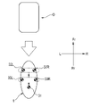
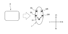
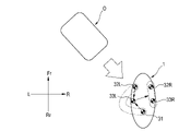
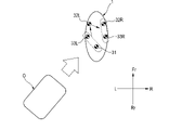
図10及び図11は、物体が車両1の後方から接近する場合の触覚刺激パターンを示す。図12は、物体が車両1の前方から接近する場合の触覚刺激パターンを示す。図13は、物体が車両1の左方から接近する場合の触覚刺激パターンを示す。図14は、物体が車両1の左斜め前方から接近する場合の触覚刺激パターンを示す。そして、図15は、物体が車両1の左斜め後方から接近する場合の触覚刺激パターンを示す。
制御部21は、第1バイブレータ31、第2左バイブレータ32L、第2右バイブレータ32R、第3左バイブレータ33L、及び第3右バイブレータ33Rそれぞれの作動タイミングをずらして、これらのバイブレータを作動させる。そして、制御部21は、第1バイブレータ31、第2左バイブレータ32L、第2右バイブレータ32R、第3左バイブレータ33L、及び第3右バイブレータ33Rを作動させる順によって複数の触覚刺激パターンを形成する。
図10及び図11に示されるように、物体Oが車両1の後方から接近する場合に、制御部21は、第1のタイミングT1で第1バイブレータ31を作動させ、次いで第2のタイミングT2で第3左バイブレータ33L及び第3右バイブレータ33Rを作動させ、最後に第3のタイミングT3で第2左バイブレータ32L及び第2右バイブレータ32Rを作動させる。運転者の触覚を刺激する振動箇所が、物体Oに近い車両後方から車両前方に向けて順に移動する。そして、以上の動作を1サイクルとして、制御部21はこのサイクルを繰り返し行う。
図12に示されるように、物体Oが車両1の前方から接近する場合には、制御部21は、まず第1のタイミングで第2左バイブレータ32L及び第2右バイブレータ32Rを作動させ、次いで第2のタイミングで第3左バイブレータ33L及び第3右バイブレータ33Rを作動させ、最後に第3のタイミングで第1バイブレータ31を作動させる。
図13に示されるように、物体Oが車両1の左方から接近する場合に、制御部21は、まず第1のタイミングで第2左バイブレータ32L及び第3左バイブレータ33Lを作動させ、次いで第2のタイミングで第1バイブレータ31を作動させ、最後に第3のタイミングで第2右バイブレータ32R及び第3右バイブレータ33Rを作動させる。
図示は省略するが、物体Oが車両1の右方から接近する場合には、制御部は、まず第1のタイミングで第2右バイブレータ32R及び第3右バイブレータ33Rを作動させ、次いで第2のタイミングで第1バイブレータ31を作動させ、最後に第3のタイミングで第2左バイブレータ32L及び第3左バイブレータ33Lを作動させる。
図14に示されるように、物体Oが車両1の左斜め前方から接近する場合に、制御部21は、まず第1のタイミングで第2左バイブレータ32L及び第1バイブレータ31を作動させ、次いで第2のタイミングで第3左バイブレータ33Lを作動させ、最後に第3のタイミングで第2右バイブレータ32R及び第3右バイブレータ33Rを作動させる。
図示は省略するが、物体Oが車両1の右斜め前方から接近する場合には、制御部21は、まず第1のタイミングで第2右バイブレータ32R及び第1バイブレータ31を作動させ、次いで第2のタイミングで第3右バイブレータ33Rを作動させ、最後に第3のタイミングで第2左バイブレータ32L及び第3左バイブレータ33Lを作動させる。
図15に示されるように、物体Oが車両1の左斜め後方から接近する場合に、制御部21は、まず第1のタイミングで第3左バイブレータ33L及び第1バイブレータ31を作動させ、次いで第2のタイミングで第2左バイブレータ32Lを作動させ、最後に第3のタイミングで第2右バイブレータ32R及び第3右バイブレータ33Rを作動させる。
図示は省略するが、物体Oが車両1の右斜め後方から接近する場合には、制御部21は、まず第1のタイミングで第3右バイブレータ33R及び第1バイブレータ31を作動させ、次いで第2のタイミングで第2右バイブレータ32Rを作動させ、最後に第3のタイミングで第2左バイブレータ32L及び第3左バイブレータ33Lを作動させる。
運転者は、触覚刺激パターンを知覚し、知覚した触覚刺激パターンに対応する方向を物体Oの接近方向として認識する。
制御部21は、車両1と物体Oとの距離に応じて、作動タイミングのずれ量及びサイクル動作の間隔を変化させてもよい。例えば、図10及び図11に示される物体Oが車両1の後方から接近する場合の触覚刺激パターンにおいて、第1バイブレータ31を作動させる第1のタイミングT1と第3左バイブレータ33L及び第3右バイブレータ33Rを作動させる第2のタイミングT2との時間間隔と、第2のタイミングT2と第2左バイブレータ32L及び第2右バイブレータ32Rを作動させる第3のタイミングT3との時間間隔とを作動タイミングのずれ量ΔTとする。また、第2左バイブレータ32L及び第2右バイブレータ32Rを停止させるタイミングT4から次のサイクルで第1バイブレータ31を作動させるタイミングT5までの時間をサイクル動作の間隔ΔTTとする。制御部21は、車両1と物体Oとの距離が縮まるほどに、作動タイミングのずれ量ΔT及びサイクル動作の間隔ΔTTを短くする。運転者は、作動タイミングのずれ量ΔT及びサイクル動作の間隔ΔTTの変化を知覚し、知覚した変化に基づいて車両1と物体Oとのおおよその距離を認識できる。
また、制御部21は、車両1と物体Oとの距離が縮まるほどに、第1バイブレータ31、第2左バイブレータ32L、第2右バイブレータ32R、第3左バイブレータ33L、及び第3右バイブレータ33Rの振幅を大きくしてもよく、また周波数を高くしてもよい。運転者は、振幅及び周波数の変化に基づいて車両1と物体Oとのおおよその距離を認識できる。
以上の触覚刺激パターンにおいて、第1バイブレータ31、第2左バイブレータ32L、第2右バイブレータ32R、第3左バイブレータ33L、及び第3右バイブレータ33Rは、物体Oに最も近いバイブレータを起点にして、互いにずれた三つの作動タイミングで順に作動している。物体Oに最も近いバイブレータが起点となることにより、運転者は物体Oの接近方向を直感的に認識できる。そして、一つの触覚刺激パターンの繰り返しにおいて、互いにずれた三つの作動タイミングは物体Oの接近方向の識別性を高める。
例えば、物体Oが車両1の後方から接近する場合の触覚刺激パターンとして、第1のタイミングで第1バイブレータ31を作動させ、次いで第2のタイミングで第2左バイブレータ32L及び第2右バイブレータ32Rを作動させる触覚刺激パターンを想定すると、この触覚刺激パターンの繰り返しは、作動タイミングのずれ量ΔT及びサイクル動作の間隔ΔTTが短い場合において、起点となるバイブレータの判別を困難にする可能性がある。一方、一つの触覚刺激パターンの繰り返しにおいて、互いにずれた三つの作動タイミングは、作動タイミングのずれ量ΔT及びサイクル動作の間隔ΔTTにかかわらず、起点となるバイブレータの判別を容易にする。これにより、物体Oの接近方向の識別性が高まる。
なお、上述した触覚刺激パターンでは、第1バイブレータ31、第2左バイブレータ32L、第2右バイブレータ32R、第3左バイブレータ33L、及び第3右バイブレータ33Rの全てのバイブレータが作動されるが、三つ以上の一部のバイブレータが作動されてもよい。例えば、物体Oが車両1の左斜め前方から接近する場合に、図16に示されるように、まず第1のタイミングで第2左バイブレータ32Lが作動され、次いで第2のタイミングで第3左バイブレータ33Lが作動され、最後に第3のタイミングで第1バイブレータ31が作動されてもよい。物体Oが車両1の左斜め後方から接近する場合に、図17に示されるように、まず第1のタイミングで第1バイブレータ31が作動され、次いで第2のタイミングで第3右バイブレータ33Rが作動され、最後に第3のタイミングで第2右バイブレータ32Rが作動されてもよい。
物体Oの接近方向に応じて異なる触覚刺激パターンは、第1バイブレータ31、第2左バイブレータ32L、第2右バイブレータ32R、第3左バイブレータ33L、及び第3右バイブレータ33Rそれぞれの作動タイミングのずれに替えて、これらのバイブレータそれぞれの刺激強度の差によって形成されてもよい。なお、振動によって運転者の触覚を刺激するバイブレータの刺激強度は、振動の振幅によって表される。
図18は、物体が車両1の後方から接近する場合の触覚刺激パターンを示す。物体Oが車両1の後方から接近する場合に、制御部21は、第1バイブレータ31、第2左バイブレータ32L、第2右バイブレータ32R、第3左バイブレータ33L、及び第3右バイブレータ33Rを同時に作動させる。そして、制御部21は、物体Oに最も近い第1バイブレータ31の振幅A1が最も大きく(刺激強度が最も高く)、物体Oから最も遠い第2左バイブレータ32L及び第2右バイブレータ32Rの振幅A2が最も小さく(刺激強度が最も低く)なるように、第1バイブレータ31、第2左バイブレータ32L、第2右バイブレータ32R、第3左バイブレータ33L、及び第3右バイブレータ33Rを作動させる。物体Oに近い車両後方から車両前方に向けて刺激強度が次第に低くなる刺激強度分布が形成される。物体Oに最も近いバイブレータの刺激強度が最も高くなることにより、運転者は物体Oの接近方向を直感的に認識できる。
なお、物体Oの接近方向に応じて異なる触覚刺激パターンは、図19に示されるように、第1バイブレータ31、第2左バイブレータ32L、第2右バイブレータ32R、第3左バイブレータ33L、及び第3右バイブレータ33Rそれぞれの作動タイミングのずれと、これらのバイブレータそれぞれの刺激強度の差との組み合わせによって形成されてもよい。
次に、図20を参照して、検知部20及び制御部21が行う処理について説明する。
まず、検知部20が、車両1に接近する物体Oの存在を検知する(ステップS1)。例えば、接近センサ22によって測定される車両1と物体との距離が第1の閾値未満である場合に、検知部20は、当該物体を車両1に接近する物体Oとして検知する。
検知部20が車両1に接近する物体Oの存在を検知した場合に(ステップS1-Yes)、制御部21は、第1バイブレータ31、第2左バイブレータ32L、第2右バイブレータ32R、第3左バイブレータ33L、及び第3右バイブレータ33Rを、物体Oの接近方向に対応する触覚刺激パターンで作動させる(ステップS2)。
第1バイブレータ31、第2左バイブレータ32L、第2右バイブレータ32R、第3左バイブレータ33L、及び第3右バイブレータ33Rの作動によって触覚を刺激された運転者が物体Oに気づき、運転者が物体Oを回避する行動をとった場合に、検知部20は車両1における物体回避動作を検知する(ステップS3)。
車両1における物体回避動作は、例えばフロントブレーキ13Fr及びリヤブレーキ13Rrの少なくとも一方の作動であり、フロントブレーキ13Fr及びリヤブレーキ13Rrの少なくとも一方の作動に起因した車両1の減速であり、又は車両1の減速に起因した車両1と物体Oとの距離の急激な変化である。また、車両1における物体回避動作は、例えばステアリング6の回動であり、又はステアリング6の回動に伴う車両1の進行方向の変化に起因した、車両1の進行方向における車両1の物体Oに対する相対速度の急激な変化である。
検知部20が車両1における物体回避動作を検知した場合に(ステップS3-Yes)、制御部21は、第1バイブレータ31、第2左バイブレータ32L、第2右バイブレータ32R、第3左バイブレータ33L、及び第3右バイブレータ33Rを停止させる(ステップS5)。運転者が物体Oを回避する行動をとった後の運転者に対する触覚刺激を停止することにより、運転者の快適性を高めることができる。
一方、車両1における物体回避動作が検知されない場合に(ステップS3-No)、検知部20は、物体Oが車両1にさらに接近するか否かを判定する(ステップS4)。
車両1と物体Oとの距離が縮まる場合に(ステップS4-Yes)、検知部20は物体Oのさらなる接近を検知する。この場合に、処理はステップS2に戻り、制御部21は、第1バイブレータ31、第2左バイブレータ32L、第2右バイブレータ32R、第3左バイブレータ33L、及び第3右バイブレータ33Rを、物体Oの接近方向に対応する触覚刺激パターンで再び作動させる。こうして、運転者に対する触覚刺激が繰り返し行われる。
一方、車両1と物体Oとの距離が拡がるか又は変化しない場合に(ステップS4-No)、検知部20による検知において物体Oは非検知となり、制御部21は、第1バイブレータ31、第2左バイブレータ32L、第2右バイブレータ32R、第3左バイブレータ33L、及び第3右バイブレータ33Rを停止させる(ステップS5)。
図21は、検知部20及び制御部21が行う処理の変形例を示す。なお、本例において、第2右バイブレータ32Rが、ブレーキレバー14を有する右ハンドルグリップ9R(ブレーキ操作部)に設けられており、第3右バイブレータ33Rが、ブレーキペダル15を有する右ステップ10R(ブレーキ操作部)に設けられているものとする。
図21に示される例では、検知部20は車両1と物体Oとの衝突リスクを推定する(ステップS6)。衝突リスクの推定において、例えば車両1と物体Oとの距離が第2の閾値(第1の閾値>第2の閾値)未満である場合に衝突リスクが高いと推定され、又は車両1と物体Oとの接近速度(車両1と物体Oとの距離の単位時間当たりの減少量)が所定の閾値を超える場合に衝突リスクが高いと推定される。
検知部20が推定する衝突リスクが高い場合に(ステップS6-Yes)、制御部21は、第2右バイブレータ32R及び第3右バイブレータ33Rの少なくとも一方を作動させる(ステップS7)。運転者は、ブレーキレバー14近傍の第2右バイブレータ32Rによる触覚刺激、及びブレーキペダル15近傍の第3右バイブレータ33Rによる触覚刺激をとおして、ブレーキ操作の必要性を認識できる。好ましくは、第2右バイブレータ32R及び第3右バイブレータ33Rは連続して作動される。ブレーキ操作部に設置されたバイブレータによる触覚刺激によってブレーキ操作の必要性を運転者に認識させることは、物体Oが車両1の前方から接近する場合に特に有用である。
以上説明した本発明の実施形態によれば、第1バイブレータ31、第2左バイブレータ32L、第2右バイブレータ32R、第3左バイブレータ33L、及び第3右バイブレータ33Rの5つのバイブレータで、コストをかけずに、物体の接近及び接近方向を運転者に認識させる。
なお、本発明は上記実施形態に限定されるものではなく、適宜、変形、改良、等が可能である。当業者であれば、請求の範囲に記載された範疇内において、各種の変更例又は修正例に想到し得ることは明らかであり、それらについても当然に本発明の技術的範囲に属するものと了解される。また、発明の趣旨を逸脱しない範囲において、上記実施の形態における各構成要素を任意に組み合わせてもよい。例えば、車両1は、エンジンに替えてモータを原動機として備える鞍乗り型車両であってもよい。
本明細書には少なくとも以下の事項が記載されている。なお、括弧内には、上記実施形態において対応する構成要素等を示しているが、これに限定されるものではない。
(1)鞍乗り型車両(1)であって、
前記鞍乗り型車両(1)の運転者の触覚を刺激可能な複数の触覚装置(31,32L,32R,33L,33R)と、
前記鞍乗り型車両(1)に対する物体(O)の接近及び接近方向を検知する検知部(20)と、
前記検知部(20)の検知結果に応じて前記複数の触覚装置(31,32L,32R,33L,33R)を制御する制御部(21)と、
を備え、
前記複数の触覚装置(31,32L,32R,33L,33R)は、
第1触覚装置(31)と、
前記第1触覚装置(31)よりも車両前方に配置され、且つ前記第1触覚装置(31)を通って車両前後方向に延びる中心線(CL)に対して車両幅方向における一方側及び他方側にそれぞれ配置された第2左触覚装置(32L)及び第2右触覚装置(32R)と、
車両前後方向における前記第1触覚装置(31)と前記第2左触覚装置(32L)及び前記第2右触覚装置(32R)との間に配置され、且つ前記中心線(CL)に対して前記一方側及び前記他方側にそれぞれ配置された第3左触覚装置(33L)及び第3右触覚装置(33R)と、
を含む鞍乗り型車両(1)。
前記鞍乗り型車両(1)の運転者の触覚を刺激可能な複数の触覚装置(31,32L,32R,33L,33R)と、
前記鞍乗り型車両(1)に対する物体(O)の接近及び接近方向を検知する検知部(20)と、
前記検知部(20)の検知結果に応じて前記複数の触覚装置(31,32L,32R,33L,33R)を制御する制御部(21)と、
を備え、
前記複数の触覚装置(31,32L,32R,33L,33R)は、
第1触覚装置(31)と、
前記第1触覚装置(31)よりも車両前方に配置され、且つ前記第1触覚装置(31)を通って車両前後方向に延びる中心線(CL)に対して車両幅方向における一方側及び他方側にそれぞれ配置された第2左触覚装置(32L)及び第2右触覚装置(32R)と、
車両前後方向における前記第1触覚装置(31)と前記第2左触覚装置(32L)及び前記第2右触覚装置(32R)との間に配置され、且つ前記中心線(CL)に対して前記一方側及び前記他方側にそれぞれ配置された第3左触覚装置(33L)及び第3右触覚装置(33R)と、
を含む鞍乗り型車両(1)。
上記(1)によれば、第1触覚装置(31)、第2左触覚装置(32L)、第2右触覚装置(32R)、第3左触覚装置(33L)、及び第3右触覚装置(33R)の5つの触覚装置で、コストをかけずに、物体の接近及び接近方向を運転者に認識させることができる。
(2) (1)記載の鞍乗り型車両(1)であって、
前記第1触覚装置(31)は、前記鞍乗り型車両(1)の運転席(5)に設けられている鞍乗り型車両(1)。
前記第1触覚装置(31)は、前記鞍乗り型車両(1)の運転席(5)に設けられている鞍乗り型車両(1)。
上記(2)によれば、運転者の腰部又は尻の触覚を刺激できる。
(3) (1)又は(2)記載の鞍乗り型車両(1)であって、
前記第2左触覚装置(32L)及び前記第2右触覚装置(32R)は、前記鞍乗り型車両(1)の左右のハンドルグリップ(9L、9R)、又は前記鞍乗り型車両(1)の運転席(5)よりも車両前方且つ前記鞍乗り型車両(1)の左右のステップ(10L、10R)よりも車両上方に位置し、運転者の脚部と接触可能な前記鞍乗り型車両(1)の左右の外表面(12L,12R,16L、16R)に設けられている鞍乗り型車両(1)。
前記第2左触覚装置(32L)及び前記第2右触覚装置(32R)は、前記鞍乗り型車両(1)の左右のハンドルグリップ(9L、9R)、又は前記鞍乗り型車両(1)の運転席(5)よりも車両前方且つ前記鞍乗り型車両(1)の左右のステップ(10L、10R)よりも車両上方に位置し、運転者の脚部と接触可能な前記鞍乗り型車両(1)の左右の外表面(12L,12R,16L、16R)に設けられている鞍乗り型車両(1)。
上記(3)によれば、運転者の手又は脚部の触覚を刺激できる。
(4) (1)又は(2)記載の鞍乗り型車両(1)であって、
前記第3左触覚装置(33L)及び前記第3右触覚装置(33R)は、前記鞍乗り型車両(1)の左右のステップ(10L、10R)、又は前記鞍乗り型車両(1)の運転席(5)よりも車両前方且つ前記左右のステップ(10L、10R)よりも車両上方に位置し、運転者の脚部と接触可能な前記鞍乗り型車両(1)の左右の外表面(12L,12R,16L、16R)に設けられている鞍乗り型車両(1)。
前記第3左触覚装置(33L)及び前記第3右触覚装置(33R)は、前記鞍乗り型車両(1)の左右のステップ(10L、10R)、又は前記鞍乗り型車両(1)の運転席(5)よりも車両前方且つ前記左右のステップ(10L、10R)よりも車両上方に位置し、運転者の脚部と接触可能な前記鞍乗り型車両(1)の左右の外表面(12L,12R,16L、16R)に設けられている鞍乗り型車両(1)。
上記(4)によれば、運転者の足又は脚部の触覚を刺激できる。
(5) (1)から(4)のいずれかに記載の鞍乗り型車両(1)であって、
前記検知部(20)は、前記鞍乗り型車両(1)における物体回避動作を検知し、
前記制御部(21)が前記複数の触覚装置(31,32L,32R,33L,33R)のうち少なくとも一部の触覚装置を作動させている状態で、前記検知部(20)が前記物体回避動作を検知した場合に、前記制御部(21)は、前記複数の触覚装置(31,32L,32R,33L,33R)を停止させる鞍乗り型車両(1)。
前記検知部(20)は、前記鞍乗り型車両(1)における物体回避動作を検知し、
前記制御部(21)が前記複数の触覚装置(31,32L,32R,33L,33R)のうち少なくとも一部の触覚装置を作動させている状態で、前記検知部(20)が前記物体回避動作を検知した場合に、前記制御部(21)は、前記複数の触覚装置(31,32L,32R,33L,33R)を停止させる鞍乗り型車両(1)。
上記(5)によれば、運転者が物体を回避する行動をとった後の運転者に対する触覚刺激を停止して、運転者の快適性を高めることができる。
(6) (5)記載の鞍乗り型車両(1)であって、
前記検知部(20)は、前記鞍乗り型車両(1)と前記物体(O)との距離及び前記鞍乗り型車両(1)の進行方向における前記鞍乗り型車両(1)の前記物体(O)に対する相対速度の少なくとも一方に基づいて、前記物体回避動作を検知する鞍乗り型車両(1)。
前記検知部(20)は、前記鞍乗り型車両(1)と前記物体(O)との距離及び前記鞍乗り型車両(1)の進行方向における前記鞍乗り型車両(1)の前記物体(O)に対する相対速度の少なくとも一方に基づいて、前記物体回避動作を検知する鞍乗り型車両(1)。
上記(6)によれば、運転者が物体を回避する行動をとったことを検知することができる。
(7) (5)又は(6)記載の鞍乗り型車両(1)であって、
前記検知部(20)は、前記鞍乗り型車両(1)のステアリング(6)の回動及び前記鞍乗り型車両(1)のブレーキ(13Fr,13Rr)の作動の少なくとも一方に基づいて、前記物体回避動作を検知する鞍乗り型車両(1)。
前記検知部(20)は、前記鞍乗り型車両(1)のステアリング(6)の回動及び前記鞍乗り型車両(1)のブレーキ(13Fr,13Rr)の作動の少なくとも一方に基づいて、前記物体回避動作を検知する鞍乗り型車両(1)。
上記(7)によれば、運転者が物体を回避する行動をとったことを検知することができる。
(8) (1)から(7)のいずれかに記載の鞍乗り型車両(1)であって、
前記制御部(21)は、前記複数の触覚装置(31,32L,32R,33L,33R)を用い、前記物体(O)の接近方向に応じて異なる触覚刺激パターンを形成する鞍乗り型車両(1)。
前記制御部(21)は、前記複数の触覚装置(31,32L,32R,33L,33R)を用い、前記物体(O)の接近方向に応じて異なる触覚刺激パターンを形成する鞍乗り型車両(1)。
上記(8)によれば、触覚刺激パターンに対応する方向を物体の接近方向として運転者に認識させることができる。
(9) (8)記載の鞍乗り型車両(1)であって、
前記制御部(21)は、前記複数の触覚装置(31,32L,32R,33L,33R)それぞれの作動タイミングをずらして前記複数の触覚装置(31,32L,32R,33L,33R)を作動させ、前記複数の触覚装置(31,32L,32R,33L,33R)の作動順によって前記複数の触覚刺激パターンを形成する鞍乗り型車両(1)。
前記制御部(21)は、前記複数の触覚装置(31,32L,32R,33L,33R)それぞれの作動タイミングをずらして前記複数の触覚装置(31,32L,32R,33L,33R)を作動させ、前記複数の触覚装置(31,32L,32R,33L,33R)の作動順によって前記複数の触覚刺激パターンを形成する鞍乗り型車両(1)。
上記(9)によれば、物体の接近方向に応じて異なる触覚刺激パターンを形成することができる。
(10) (9)記載の鞍乗り型車両(1)であって、
前記制御部(21)は、前記物体(O)に最も近い触覚装置を起点にして前記複数の触覚装置(31,32L,32R,33L,33R)を作動させる鞍乗り型車両(1)。
前記制御部(21)は、前記物体(O)に最も近い触覚装置を起点にして前記複数の触覚装置(31,32L,32R,33L,33R)を作動させる鞍乗り型車両(1)。
上記(10)によれば、物体の接近方向を運転者に直感的に認識させることができる。
(11) (9)又は(10)記載の鞍乗り型車両(1)であって、
前記制御部(21)は、前記鞍乗り型車両(1)と前記物体(O)との距離に応じて前記複数の触覚装置(31,32L,32R,33L,33R)の作動タイミングのずれ量(ΔT)を変化させる鞍乗り型車両(1)。
前記制御部(21)は、前記鞍乗り型車両(1)と前記物体(O)との距離に応じて前記複数の触覚装置(31,32L,32R,33L,33R)の作動タイミングのずれ量(ΔT)を変化させる鞍乗り型車両(1)。
上記(11)によれば、鞍乗り型車両と物体とのおおよその距離を運転者に認識させることができる。
(12) (8)から(11)のいずれかに記載の鞍乗り型車両(1)であって、
前記制御部(21)は、前記複数の触覚装置(31,32L,32R,33L,33R)それぞれの刺激強度を異ならせて前記複数の触覚装置(31,32L,32R,33L,33R)を作動させ、前記複数の触覚装置(31,32L,32R,33L,33R)の刺激強度の分布によって前記複数の触覚刺激パターンを形成する鞍乗り型車両(1)。
前記制御部(21)は、前記複数の触覚装置(31,32L,32R,33L,33R)それぞれの刺激強度を異ならせて前記複数の触覚装置(31,32L,32R,33L,33R)を作動させ、前記複数の触覚装置(31,32L,32R,33L,33R)の刺激強度の分布によって前記複数の触覚刺激パターンを形成する鞍乗り型車両(1)。
上記(12)によれば、物体の接近方向に応じて異なる触覚刺激パターンを形成することができる。
(13) (12)記載の鞍乗り型車両(1)であって、
前記制御部(21)は、前記物体(O)に最も近い触覚装置の刺激強度を最も高くする鞍乗り型車両(1)。
前記制御部(21)は、前記物体(O)に最も近い触覚装置の刺激強度を最も高くする鞍乗り型車両(1)。
上記(13)によれば、物体の接近方向を運転者に直感的に認識させることができる。
(14) (1)から(13)のいずれかに記載の鞍乗り型車両(1)であって、
前記複数の触覚装置(31,32L,32R,33L,33R)のうち少なくとも一つの触覚装置は、前記鞍乗り型車両(1)のブレーキ(13Fr,13Rr)の操作部(9R,10R)に設けられており、
前記鞍乗り型車両(1)と前記物体(O)との距離が所定の閾値未満である場合に、前記制御部(21)は、前記操作部(9R,10R)に設けられている触覚装置を作動させる鞍乗り型車両(1)。
前記複数の触覚装置(31,32L,32R,33L,33R)のうち少なくとも一つの触覚装置は、前記鞍乗り型車両(1)のブレーキ(13Fr,13Rr)の操作部(9R,10R)に設けられており、
前記鞍乗り型車両(1)と前記物体(O)との距離が所定の閾値未満である場合に、前記制御部(21)は、前記操作部(9R,10R)に設けられている触覚装置を作動させる鞍乗り型車両(1)。
上記(14)によれば、鞍乗り型車両と物体との衝突のリスクが高い場合などにおいて、ブレーキ操作の必要性を運転者に認識させることができる。
(15) (1)から(14)のいずれかに記載の鞍乗り型車両(1)であって、
前記複数の触覚装置(31,32L,32R,33L,33R)は、複数のバイブレータである鞍乗り型車両(1)。
前記複数の触覚装置(31,32L,32R,33L,33R)は、複数のバイブレータである鞍乗り型車両(1)。
上記(15)によれば、振動の振幅及び周波数を利用して、触覚刺激の態様を多様化できる。
なお、本出願は、2021年3月22日出願の日本特許出願(特願2021-047425)に基づくものであり、その内容は本出願の中に参照として援用される。
1 鞍乗り型車両
2 車体
3 前輪
4 後輪
5 運転席
6 ステアリング
7 スイングアーム
8 ハンドル
9L 左ハンドルグリップ
9R 右ハンドルグリップ
10L 左ステップ
10R 右ステップ
11 燃料タンク
12L 左サイドカバー
12R 右サイドカバー
13Fr フロントブレーキ
13Rr リヤブレーキ
14 ブレーキレバー
15 ブレーキペダル
20 検知部
21 制御部
22 接近センサ
23 ステアリングセンサ
24 ブレーキセンサ
31 第1バイブレータ(第1触覚装置)
32L 第2左バイブレータ(第2左触覚装置)
32R 第2右バイブレータ(第2右触覚装置)
33L 第3左バイブレータ(第3左触覚装置)
33R 第3右バイブレータ(第3右触覚装置)
CL 中心線
O 物体
2 車体
3 前輪
4 後輪
5 運転席
6 ステアリング
7 スイングアーム
8 ハンドル
9L 左ハンドルグリップ
9R 右ハンドルグリップ
10L 左ステップ
10R 右ステップ
11 燃料タンク
12L 左サイドカバー
12R 右サイドカバー
13Fr フロントブレーキ
13Rr リヤブレーキ
14 ブレーキレバー
15 ブレーキペダル
20 検知部
21 制御部
22 接近センサ
23 ステアリングセンサ
24 ブレーキセンサ
31 第1バイブレータ(第1触覚装置)
32L 第2左バイブレータ(第2左触覚装置)
32R 第2右バイブレータ(第2右触覚装置)
33L 第3左バイブレータ(第3左触覚装置)
33R 第3右バイブレータ(第3右触覚装置)
CL 中心線
O 物体
Claims (15)
- 鞍乗り型車両(1)であって、
前記鞍乗り型車両(1)の運転者の触覚を刺激可能な複数の触覚装置(31,32L,32R,33L,33R)と、
前記鞍乗り型車両(1)に対する物体(O)の接近及び接近方向を検知する検知部(20)と、
前記検知部(20)の検知結果に応じて前記複数の触覚装置(31,32L,32R,33L,33R)を制御する制御部(21)と、
を備え、
前記複数の触覚装置(31,32L,32R,33L,33R)は、
第1触覚装置(31)と、
前記第1触覚装置(31)よりも車両前方に配置され、且つ前記第1触覚装置(31)を通って車両前後方向に延びる中心線(CL)に対して車両幅方向における一方側及び他方側にそれぞれ配置された第2左触覚装置(32L)及び第2右触覚装置(32R)と、
車両前後方向における前記第1触覚装置(31)と前記第2左触覚装置(32L)及び前記第2右触覚装置(32R)との間に配置され、且つ前記中心線(CL)に対して前記一方側及び前記他方側にそれぞれ配置された第3左触覚装置(33L)及び第3右触覚装置(33R)と、
を含む鞍乗り型車両(1)。 - 請求項1記載の鞍乗り型車両(1)であって、
前記第1触覚装置(31)は、前記鞍乗り型車両(1)の運転席(5)に設けられている鞍乗り型車両(1)。 - 請求項1又は2記載の鞍乗り型車両(1)であって、
前記第2左触覚装置(32L)及び前記第2右触覚装置(32R)は、前記鞍乗り型車両(1)の左右のハンドルグリップ(9L、9R)、又は前記鞍乗り型車両(1)の運転席(5)よりも車両前方且つ前記鞍乗り型車両(1)の左右のステップ(10L、10R)よりも車両上方に位置し、運転者の脚部と接触可能な前記鞍乗り型車両(1)の左右の外表面(12L,12R,16L、16R)に設けられている鞍乗り型車両(1)。 - 請求項1又は2記載の鞍乗り型車両(1)であって、
前記第3左触覚装置(33L)及び前記第3右触覚装置(33R)は、前記鞍乗り型車両(1)の左右のステップ(10L、10R)、又は前記鞍乗り型車両(1)の運転席(5)よりも車両前方且つ前記左右のステップ(10L、10R)よりも車両上方に位置し、運転者の脚部と接触可能な前記鞍乗り型車両(1)の左右の外表面(12L,12R,16L、16R)に設けられている鞍乗り型車両(1)。 - 請求項1から4のいずれか一項記載の鞍乗り型車両(1)であって、
前記検知部(20)は、前記鞍乗り型車両(1)における物体回避動作を検知し、
前記制御部(21)が前記複数の触覚装置(31,32L,32R,33L,33R)のうち少なくとも一部の触覚装置を作動させている状態で、前記検知部(20)が前記物体回避動作を検知した場合に、前記制御部(21)は、前記複数の触覚装置(31,32L,32R,33L,33R)を停止させる鞍乗り型車両(1)。 - 請求項5記載の鞍乗り型車両(1)であって、
前記検知部(20)は、前記鞍乗り型車両(1)と前記物体(O)との距離及び前記鞍乗り型車両(1)の進行方向における前記鞍乗り型車両(1)の前記物体(O)に対する相対速度の少なくとも一方に基づいて、前記物体回避動作を検知する鞍乗り型車両(1)。 - 請求項5又は6記載の鞍乗り型車両(1)であって、
前記検知部(20)は、前記鞍乗り型車両(1)のステアリング(6)の回動及び前記鞍乗り型車両(1)のブレーキ(13Fr,13Rr)の作動の少なくとも一方に基づいて、前記物体回避動作を検知する鞍乗り型車両(1)。 - 請求項1から7のいずれか一項記載の鞍乗り型車両(1)であって、
前記制御部(21)は、前記複数の触覚装置(31,32L,32R,33L,33R)を用い、前記物体(O)の接近方向に応じて異なる触覚刺激パターンを形成する鞍乗り型車両(1)。 - 請求項8記載の鞍乗り型車両(1)であって、
前記制御部(21)は、前記複数の触覚装置(31,32L,32R,33L,33R)それぞれの作動タイミングをずらして前記複数の触覚装置(31,32L,32R,33L,33R)を作動させ、前記複数の触覚装置(31,32L,32R,33L,33R)の作動順によって前記複数の触覚刺激パターンを形成する鞍乗り型車両(1)。 - 請求項9記載の鞍乗り型車両(1)であって、
前記制御部(21)は、前記物体(O)に最も近い触覚装置を起点にして前記複数の触覚装置(31,32L,32R,33L,33R)を作動させる鞍乗り型車両(1)。 - 請求項9又は10記載の鞍乗り型車両(1)であって、
前記制御部(21)は、前記鞍乗り型車両(1)と前記物体(O)との距離に応じて前記複数の触覚装置(31,32L,32R,33L,33R)の作動タイミングのずれ量(ΔT)を変化させる鞍乗り型車両(1)。 - 請求項8から11のいずれか一項記載の鞍乗り型車両(1)であって、
前記制御部(21)は、前記複数の触覚装置(31,32L,32R,33L,33R)それぞれの刺激強度を異ならせて前記複数の触覚装置(31,32L,32R,33L,33R)を作動させ、前記複数の触覚装置(31,32L,32R,33L,33R)の刺激強度の分布によって前記複数の触覚刺激パターンを形成する鞍乗り型車両(1)。 - 請求項12記載の鞍乗り型車両(1)であって、
前記制御部(21)は、前記物体(O)に最も近い触覚装置の刺激強度を最も高くする鞍乗り型車両(1)。 - 請求項1から13のいずれか一項記載の鞍乗り型車両(1)であって、
前記複数の触覚装置(31,32L,32R,33L,33R)のうち少なくとも一つの触覚装置は、前記鞍乗り型車両(1)のブレーキ(13Fr,13Rr)の操作部(9R,10R)に設けられており、
前記鞍乗り型車両(1)と前記物体(O)との距離が所定の閾値未満である場合に、前記制御部(21)は、前記操作部(9R,10R)に設けられている触覚装置を作動させる鞍乗り型車両(1)。 - 請求項1から14のいずれか一項記載の鞍乗り型車両(1)であって、
前記複数の触覚装置(31,32L,32R,33L,33R)は、複数のバイブレータである鞍乗り型車両(1)。
Applications Claiming Priority (2)
| Application Number | Priority Date | Filing Date | Title |
|---|---|---|---|
| JP2021047425 | 2021-03-22 | ||
| JP2021-047425 | 2021-03-22 |
Publications (1)
| Publication Number | Publication Date |
|---|---|
| WO2022201864A1 true WO2022201864A1 (ja) | 2022-09-29 |
Family
ID=83396840
Family Applications (1)
| Application Number | Title | Priority Date | Filing Date |
|---|---|---|---|
| PCT/JP2022/003612 Ceased WO2022201864A1 (ja) | 2021-03-22 | 2022-01-31 | 鞍乗り型車両 |
Country Status (1)
| Country | Link |
|---|---|
| WO (1) | WO2022201864A1 (ja) |
Citations (5)
| Publication number | Priority date | Publication date | Assignee | Title |
|---|---|---|---|---|
| JP2016034819A (ja) * | 2014-08-04 | 2016-03-17 | 株式会社エフ・シー・シー | 鞍乗り型車両 |
| JP2016068606A (ja) * | 2014-09-26 | 2016-05-09 | 本田技研工業株式会社 | 鞍乗型車両の接近報知装置 |
| JP2017206242A (ja) * | 2016-05-17 | 2017-11-24 | 富士通株式会社 | 自転車のための運転者警告システム、及び自転車運転者のための運転者警告方法 |
| CN111114673A (zh) * | 2019-12-27 | 2020-05-08 | 南京安捷智造科技有限公司 | 雷视一体的电动自行车后向防碰撞系统及提示方法 |
| JP2020152377A (ja) * | 2020-06-11 | 2020-09-24 | テイ・エス テック株式会社 | 乗物用報知ユニット |
-
2022
- 2022-01-31 WO PCT/JP2022/003612 patent/WO2022201864A1/ja not_active Ceased
Patent Citations (5)
| Publication number | Priority date | Publication date | Assignee | Title |
|---|---|---|---|---|
| JP2016034819A (ja) * | 2014-08-04 | 2016-03-17 | 株式会社エフ・シー・シー | 鞍乗り型車両 |
| JP2016068606A (ja) * | 2014-09-26 | 2016-05-09 | 本田技研工業株式会社 | 鞍乗型車両の接近報知装置 |
| JP2017206242A (ja) * | 2016-05-17 | 2017-11-24 | 富士通株式会社 | 自転車のための運転者警告システム、及び自転車運転者のための運転者警告方法 |
| CN111114673A (zh) * | 2019-12-27 | 2020-05-08 | 南京安捷智造科技有限公司 | 雷视一体的电动自行车后向防碰撞系统及提示方法 |
| JP2020152377A (ja) * | 2020-06-11 | 2020-09-24 | テイ・エス テック株式会社 | 乗物用報知ユニット |
Similar Documents
| Publication | Publication Date | Title |
|---|---|---|
| US8412390B2 (en) | Information presentation device | |
| US12224744B2 (en) | Motorcycle with haptic braking hazard alert | |
| JP6803301B2 (ja) | 自律制動を有する鞍乗り型車両及び自律制動を動作させる方法 | |
| CN103569134B (zh) | 用于车辆的警示系统和方法 | |
| JP7033193B2 (ja) | 鞍乗り型車両 | |
| JP2006264624A (ja) | 車線維持支援装置 | |
| US12570308B2 (en) | Motor vehicle and method of operating a motor vehicle | |
| JP2004210261A (ja) | シートベルト着用促進装置 | |
| US12151770B2 (en) | Switchgear for vehicle and vehicle including switchgear | |
| JP2009120015A (ja) | 車両用シート及び車両用警報装置 | |
| JP7414838B2 (ja) | 鞍乗り型車両 | |
| CN116685512A (zh) | 骑手辅助系统的控制装置及控制方法 | |
| JP2020100229A (ja) | 鞍乗型車両のライダー支援システムのための処理装置及び処理方法、鞍乗型車両のライダー支援システム、及び、鞍乗型車両 | |
| JPH11350983A5 (ja) | ||
| EP4105091B1 (en) | Controller and control method for a rider-assistance system on a straddle-type vehicle | |
| WO2022201864A1 (ja) | 鞍乗り型車両 | |
| JP7741871B2 (ja) | ライダー支援システムの制御装置及び制御方法 | |
| JP2022096469A (ja) | 制御装置及び制御方法 | |
| JP7168431B2 (ja) | 鞍乗型車両の警告システムのための処理装置及び処理方法、鞍乗型車両の警告システム、及び、鞍乗型車両 | |
| JP7842852B2 (ja) | 鞍乗り型車両の制御装置及び制御方法 | |
| JP2006168614A (ja) | 車両用走行制御装置 | |
| JP7821026B2 (ja) | 車両用シート | |
| JP5093603B2 (ja) | 危険状況報知装置 | |
| CN114228737A (zh) | 用于动能回收的震动反馈的方法和震动反馈系统 | |
| JP2008158671A (ja) | 車両用衝突警報装置 |
Legal Events
| Date | Code | Title | Description |
|---|---|---|---|
| 121 | Ep: the epo has been informed by wipo that ep was designated in this application |
Ref document number: 22774666 Country of ref document: EP Kind code of ref document: A1 |
|
| NENP | Non-entry into the national phase |
Ref country code: DE |
|
| 122 | Ep: pct application non-entry in european phase |
Ref document number: 22774666 Country of ref document: EP Kind code of ref document: A1 |
|
| NENP | Non-entry into the national phase |
Ref country code: JP |