WO2022201751A1 - 鍵盤装置 - Google Patents
鍵盤装置 Download PDFInfo
- Publication number
- WO2022201751A1 WO2022201751A1 PCT/JP2022/000723 JP2022000723W WO2022201751A1 WO 2022201751 A1 WO2022201751 A1 WO 2022201751A1 JP 2022000723 W JP2022000723 W JP 2022000723W WO 2022201751 A1 WO2022201751 A1 WO 2022201751A1
- Authority
- WO
- WIPO (PCT)
- Prior art keywords
- weight member
- weight
- keyboard device
- key
- hammer assembly
- Prior art date
- Legal status (The legal status is an assumption and is not a legal conclusion. Google has not performed a legal analysis and makes no representation as to the accuracy of the status listed.)
- Ceased
Links
Images






Classifications
-
- G—PHYSICS
- G10—MUSICAL INSTRUMENTS; ACOUSTICS
- G10H—ELECTROPHONIC MUSICAL INSTRUMENTS; INSTRUMENTS IN WHICH THE TONES ARE GENERATED BY ELECTROMECHANICAL MEANS OR ELECTRONIC GENERATORS, OR IN WHICH THE TONES ARE SYNTHESISED FROM A DATA STORE
- G10H1/00—Details of electrophonic musical instruments
- G10H1/32—Constructional details
- G10H1/34—Switch arrangements, e.g. keyboards or mechanical switches specially adapted for electrophonic musical instruments
- G10H1/344—Structural association with individual keys
- G10H1/346—Keys with an arrangement for simulating the feeling of a piano key, e.g. using counterweights, springs, cams
-
- G—PHYSICS
- G10—MUSICAL INSTRUMENTS; ACOUSTICS
- G10C—PIANOS, HARPSICHORDS, SPINETS OR SIMILAR STRINGED MUSICAL INSTRUMENTS WITH ONE OR MORE KEYBOARDS
- G10C3/00—Details or accessories
- G10C3/12—Keyboards; Keys
-
- G—PHYSICS
- G10—MUSICAL INSTRUMENTS; ACOUSTICS
- G10H—ELECTROPHONIC MUSICAL INSTRUMENTS; INSTRUMENTS IN WHICH THE TONES ARE GENERATED BY ELECTROMECHANICAL MEANS OR ELECTRONIC GENERATORS, OR IN WHICH THE TONES ARE SYNTHESISED FROM A DATA STORE
- G10H2220/00—Input/output interfacing specifically adapted for electrophonic musical tools or instruments
- G10H2220/155—User input interfaces for electrophonic musical instruments
- G10H2220/265—Key design details; Special characteristics of individual keys of a keyboard; Key-like musical input devices, e.g. finger sensors, pedals, potentiometers, selectors
- G10H2220/275—Switching mechanism or sensor details of individual keys, e.g. details of key contacts, hall effect or piezoelectric sensors used for key position or movement sensing purposes; Mounting thereof
Definitions
- One embodiment of the present invention relates to a keyboard device. More particularly, one embodiment of the present invention relates to a keyboard apparatus with hammer assemblies having different moments of inertia for different keys.
- Acoustic pianos such as conventional grand pianos and upright pianos consist of many parts.
- Conventional pianos are provided with hammer assemblies having weights (hereinafter referred to as weight members) below the keys in order to give a feel (hereinafter referred to as touch feeling) to the fingers of the player through the keys (for example, Patent document 1).
- electronic keyboard devices have adopted a configuration in which hammer assemblies having different moments of inertia for keys belonging to different musical scales are used in order to achieve a touch feeling similar to that of a conventional piano.
- One of the objects of one embodiment of the present invention is to provide a keyboard device whose size in the depth direction is reduced.
- a keyboard device includes a frame, a first member, a key, and a hammer assembly that rotates according to movement of the key.
- the hammer assembly includes a rotating member connected to the frame so as to be rotatable about a rotating shaft; a weight member attached to the rotating member and having a first portion and a second portion; have The second portion faces the first member in the first direction in which the rotation shaft extends, the thickness of the second portion is smaller than the thickness of the first portion in the first direction, and the thickness of the weight member In the direction of rotation, the length of the second portion is greater than the length of the first portion.
- a keyboard device includes a frame, a first member, a key, and a hammer assembly that rotates according to movement of the key.
- the hammer assembly includes a rotating member connected to the frame so as to be rotatable about a rotating shaft; a weight member attached to the rotating member and having a first portion and a second portion; have The second portion faces the first member in the first direction in which the rotation shaft extends, and the second portion has a shape in which the first portion is crushed in the first direction.
- a plurality of the hammer assemblies may be provided, and the first member may be a part of the frame or a member fixed to the frame, and may be provided between adjacent hammer assemblies.
- the first member may be a boss.
- the first member may be a rib.
- the first member may be a guide that restricts movement of the hammer assembly in the first direction.
- the weight member may be rod-shaped, and the second portion may be a rod-shaped end.
- the weight member may be rod-shaped, and the second portion may be covered with the rotating member.
- FIG. 1 is a diagram showing the configuration of a keyboard device according to an embodiment of the present invention
- FIG. 1 is a block diagram showing the configuration of a tone generator device according to an embodiment of the present invention
- FIG. FIG. 4 is an explanatory diagram of the configuration inside the housing in the embodiment of the present invention when viewed from the side
- FIG. 4 is a side view showing an example of different grade hammer assemblies in accordance with an embodiment of the present invention
- FIG. 4 is a side view showing an example of different grade hammer assemblies in accordance with an embodiment of the present invention
- FIG. 4 is a side view showing an example of different grade hammer assemblies in accordance with an embodiment of the present invention
- FIG. 4 is a side view showing an example of different grade hammer assemblies in accordance with an embodiment of the present invention
- FIG. 4 is a side view showing an example of different grade hammer assemblies in accordance with an embodiment of the present invention
- FIG. 1 is a diagram showing the configuration of a keyboard device according to an embodiment of
- FIG. 5 is a diagram showing the plane of rotation of the center line of each weight member within the rotation range of the hammer assembly for weight members having different masses in the embodiment.
- FIG. 3 shows an example of a hammer assembly in accordance with one embodiment of the present invention
- FIG. 3 shows an example of a hammer assembly in accordance with one embodiment of the present invention
- FIG. 4 is a top view of the configuration in which the hammer assembly is attached to the frame in one embodiment of the present invention
- It is a figure which shows an example of the weight member in one Embodiment of this invention.
- FIG. 4 is a top view of the configuration in which the hammer assembly is attached to the frame in one embodiment of the present invention
- FIG. 4 is a top view of the configuration in which the hammer assembly is attached to the frame in one embodiment of the present invention
- FIG. 4 is a top view of the configuration in which the hammer assembly is attached to the frame in one embodiment of the present invention
- FIG. 4 is a top view of the configuration in which the hammer assembly is attached to the frame in one embodiment of the present invention
- a keyboard device will be described in detail below with reference to the drawings.
- the embodiments shown below are examples of embodiments of the present invention, and the present invention should not be construed as being limited to these embodiments.
- the same reference numerals or similar reference numerals are attached to identical parts or parts having similar functions. Repetitive description may be omitted.
- the dimensional ratios in the drawings may differ from actual ratios for convenience of explanation, and some components may be omitted from the drawings.
- FIG. 1 is a diagram showing the configuration of the keyboard device according to the first embodiment.
- the keyboard device 1 is an electronic keyboard instrument such as an electronic piano that produces sounds in response to key depression by a user (performer).
- the keyboard device 1 may be a keyboard-type controller that outputs control data (for example, MIDI) for controlling an external sound source device in response to key depression. In this case, the keyboard device 1 does not have to have a sound source device.
- the keyboard device 1 includes a keyboard assembly 10 .
- the keyboard assembly 10 includes white keys 100w and black keys 100b. When there is no need to distinguish between the white key 100w and the black key 100b, they are simply referred to as the key 100.
- FIG. A plurality of white keys 100w and black keys 100b are arranged side by side. The number of keys 100 is N, 88 in this example. The direction in which these keys 100 are arranged is called the scale direction.
- a structure with a sign (number) followed by "w” means a structure corresponding to a white key.
- a configuration with a sign (number) followed by "b” means a configuration corresponding to a black key.
- a part of the keyboard assembly 10 exists inside the housing 90 .
- the portion of the keyboard assembly 10 that is covered by the housing 90 is called a non-appearance portion NV, and the portion that is exposed from the housing 90 and visible to the user is called an appearance portion PV.
- the appearance part PV is a part of the key 100 and indicates an area in which the user can perform performance operations.
- the portion of the key 100 exposed by the exterior portion PV may be referred to as a key body portion.
- a sound source device 70 and a speaker 80 are arranged inside the housing 90 .
- Sound source device 70 generates a sound waveform signal in response to depression of key 100 .
- the speaker 80 outputs the sound waveform signal generated by the sound source device 70 to an external space.
- the keyboard device 1 may include a slider for controlling volume, a switch for switching tone colors, a display for displaying various information, and the like.
- directions such as up, down, left, right, front, and back indicate directions when the keyboard device 1 is viewed from the performer when performing.
- the non-appearance portion NV is located on the back side of the appearance portion PV.
- directions are indicated with the key 100 as a reference, such as the front end side of the key (front side of the key) and the rear end side of the key (rear side of the key).
- the key front end side indicates the front side of the key 100 as seen from the player.
- the rear end side of the key indicates the back side of the key 100 as seen from the player.
- the black key 100b it can be expressed that the portion from the front end to the rear end of the key body portion of the black key 100b protrudes upward from the white key 100w.
- FIG. 2 is a block diagram showing the configuration of the tone generator device according to the first embodiment.
- the sound source device 70 includes a signal conversion section 710 , a sound source section 730 and an output section 750 .
- the sensor 300 is provided corresponding to each key 100, detects the operation of the key, and outputs a signal corresponding to the content of the detection. In this example, the sensor 300 outputs a signal according to three levels of key depression amounts. The key depression speed can be detected according to the interval of this signal.
- the signal converter 710 acquires output signals from the sensors 300 (sensors 300-1, 300-2, . . . , 300-88 corresponding to the 88 keys 100), Generates and outputs operation signals.
- the operation signal is a MIDI format signal.
- the signal converting section 710 outputs note-on in response to the key depression operation. At this time, a key number indicating which of the 88 keys 100 has been operated and a velocity corresponding to the key depression speed are output in association with note-on.
- the signal converting section 710 outputs the key number and note-off in association with each other.
- a signal corresponding to another operation such as a pedal operation may be input to the signal conversion unit 710 and reflected in the operation signal.
- the sound source section 730 generates a sound waveform signal based on the operation signal output from the signal conversion section 710 .
- the output section 750 outputs the sound waveform signal generated by the sound source section 730 .
- This sound waveform signal is output to, for example, the speaker 80 or a sound waveform signal output terminal.
- FIG. 3 is an explanatory diagram of the configuration inside the housing in the first embodiment when viewed from the side.
- the white key 100w will be exemplified, but the hammer assembly 200 according to the present embodiment can also be used for the black key 100b, and is not limited to the hammer assembly 200 used for the white key 100w.
- the keyboard assembly 10 and the speaker 80 are arranged inside the housing 90 .
- the speaker 80 is arranged on the far side of the keyboard assembly 10 .
- the speaker 80 is arranged to output sounds corresponding to key depressions upward and downward of the housing 90 .
- the sound that is output downward travels from the bottom surface side of the housing 90 to the outside.
- the sound output upward passes through the space inside the keyboard assembly 10 from the inside of the housing 90 and reaches the gap between the adjacent white keys 100w or the gap between the white keys 100w and the housing 90 in the exterior portion PV. go outside from
- the keyboard assembly 10 includes a hammer assembly 200, a frame 500, a connecting portion 800, and a mounting portion 900 in addition to the white keys 100w and the sensor 300 described above.
- the keyboard assembly 10 is mostly a resin structure manufactured by injection molding or the like.
- Frame 500 is fixed to housing 90 .
- the mounting portion 900 is fixed to the frame 500 .
- the connection portion 800 is attached to the attachment portion 900 and connects the white key 100w to the frame 500 so as to be rotatable.
- the white key 100w includes a key body portion 110w and a key support portion 120w.
- the key body portion 110w is connected to the connection portion 800 via the key support portion 120w.
- the key support portion 120w is a plate-like member. A portion of the key support portion 120w is thinner in the plate thickness direction than other portions and has flexibility. A part of the key support portion 120 w is bent by the flexibility, and the white key 100 w rotates with respect to the frame 500 .
- the white key 100w has a front end key guide 150w.
- the front end key guide 150w is in slidable contact while covering the front end frame guide 510 of the frame 500. As shown in FIG.
- the front end key guide 150w is in contact with the front end frame guide 510 on both its top and bottom sides in the scale direction.
- the black key 100b is not provided with a member corresponding to the front end key guide 150w.
- the hammer assembly 200 is rotatably attached to a shaft provided on the frame 500 .
- a bearing member 220 provided in the hammer assembly 200 is rotatably attached to the shaft portion.
- the shaft portion may be referred to as a fixed member fixed to the frame 500 .
- the bearing member 220 may be referred to as a rotating member that is rotatably connected to the fixed member.
- the front end member 210 of the hammer assembly 200 comes into contact with the hammer support 130w in the internal space of the hammer support 130w in the white key 100w so as to be slidable in the front-rear direction.
- This sliding portion ie, the portion where the front end member 210 and the hammer support portion 130w contact each other, is located below the white key 100w in the exterior portion PV (forward of the rear end of the key body portion 110w).
- the hammer assembly 200 has a weight member 230 made of metal on the back side of the rotary shaft of the hammer assembly 200 . Normally (when no key is pressed), the weight member 230 is placed on the lower stopper 410, and the front end member 210 of the hammer assembly 200 pushes the white key 100w upward. When the key is depressed, the weight member 230 moves upward and collides with the upper stopper 430 . That is, the hammer assembly 200 rotates according to the movement of the white key 100w. The weight member 230 allows the hammer assembly 200 to apply weight to key depression.
- the lower stopper 410 and the upper stopper 430 are made of cushioning material or the like (nonwoven fabric, elastic material, or the like).
- a sensor 300 is attached to the frame 500 below the key body 110w. When the sensor 300 is crushed by the lower surface side of the key body portion 110w due to key depression, the sensor 300 outputs a detection signal.
- the sensor 300 is provided corresponding to each key 100 as described above.
- the bearing member 220 provided in the hammer assembly 200 is rotatably attached to the shaft portion provided in the frame 500.
- a member corresponding to the portion may be provided, and the frame 500 may be provided with a member corresponding to the bearing member 220 .
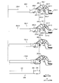
- FIG. 4 is a side view showing an example of different grade hammer assemblies in accordance with one embodiment of the present invention.
- hammer assembly 200 includes front end member 210 , bearing member 220 , weight member 230 , body member 240 , weight support member 250 and marker member 260 .
- Four types of hammer assemblies 200 are shown in FIG.
- hammer assemblies 200-1, 200-2, 200-3 and 200-4 are shown.
- branch number such as "-1" after the reference numerals.
- the main body member 240 is a member that constitutes the main portion of the hammer assembly 200 excluding the weight member 230 and that functions as the frame of the hammer assembly 200 .
- Body member 240 includes ribs 241 and recesses 242 .
- the rigidity of the body member 240 is ensured by the ribs 241 , and the weight of the body member 240 is reduced by the recesses 242 .
- the presence of the concave portion 242 improves the easiness of resin molding of the main body member 240 .
- Rib 241 extends in a direction inclined with respect to the direction in which weight member 230 extends. However, the direction in which rib 241 extends does not have to be inclined with respect to the direction in which weight member 230 extends.
- the front end member 210 is slidably attached to the hammer support portion 130w as described above. Front end member 210 protrudes from body member 240 in a direction away from bearing member 220 .
- the front end member 210 has bifurcated projecting portions on the upper and lower sides, and the hammer support portion 130w slides in the groove portion between the two projecting portions.
- the bearing member 220 has a shape that can be attached to the shaft. Specifically, the bearing member 220 is configured by an arc-shaped inner wall, and is provided with an opening 243 for attachment to the shaft. When attaching the hammer assembly 200 to the shank, the hammer assembly 200 moves so that the shank passes through the opening 243 and reaches the bearing member 220 . Note that the bearing member 220 is attached to the shaft portion by a snap-fit method. That is, the width of the open end of the bearing member 220 is smaller than the diameter of the shaft.
- the weight support member 250 is provided on the side opposite to the front end member 210 with respect to the bearing member 220 . In this embodiment, the weight support member 250 protrudes from the body member 240 in the opposite direction to the front end member 210 . The weight support member 250 fixes the weight member 230 while partially covering the weight member 230 .
- the weight support member 250 is resin-molded with the weight member 230 disposed inside the weight support member 250 . In hammer assemblies 200-1 to 200-4, the weight support members 250-1 to 250-4 have different shapes because the positions of the weight members 230 with respect to the respective weight support members 250 are different.
- a recess 251 is provided in the weight support member 250 . The recesses 251 are provided at two locations so as to sandwich the weight member 230 . During the resin molding, the weight member 230 is sandwiched between the concave portions 251 during the resin molding.
- the weight member 230 is fixed at the weight support member 250 and extends away from the body member 240 . That is, the weight member 230 is rod-shaped. Weight member 230 is shown removed from weight support member 250 below four hammer assemblies 200-1 through 200-4 in FIG. Weight member 230 includes a first portion 231 and a second portion 232 . In this embodiment, the entire second portion 232 and part of the first portion 231 are covered with the weight support member 250 . Although the detailed configuration of the weight member 230 will be described later, the first portion 231 has a length in the longitudinal direction of the key 100 . The cross-sectional shape of the first portion 231 perpendicular to the longitudinal direction is circular. That is, the first portion 231 is cylindrical. The second portion 232 has a shape in which the first portion 231 is crushed.
- the cross-sectional shape of the first portion 231 is circular
- the cross-sectional shape of the first portion 231 is rod-shaped
- the cross-sectional shape of the first portion 231 is circular or square, and [short side/long side] is 3/3.
- a rectangle of 4 or more and less than 1, or a rectangle circumscribing the cross-sectional shape, where the ratio of the first side and the second side orthogonal to each other [first side / second side] is 3/4 or more and 4/3 or less means.
- the cross-sectional shape of the second portion 232 is a plate-like shape means that the cross-sectional shape of the second portion 232 is a rectangle having a [short side/long side] of less than 3/4, or a rectangle circumscribing the cross-sectional shape. It means that the ratio of the first side to the second side [first side/second side] is less than 3/4 or greater than 4/3.
- the weight member 230 has the same cross-sectional shape (cross-sectional shape orthogonal to the longitudinal direction) at a plurality of arbitrary points in the longitudinal direction, except for the second portion 232 .
- the weight member 230 has the same cross-sectional shape at a plurality of arbitrary points in the longitudinal direction in a region that is longer than half of the total length of the weight member 230 in the longitudinal direction.
- the cross-sectional shape of member 230 is the same.
- the cross-sectional shape of weight member 230-1 exposed from weight support member 250-1 is substantially uniform in the longitudinal direction of weight member 230-1.
- the shape of the second portion 232 is a shape in which the first portion 231 is crushed. ) have the same cross-sectional area (a cross-sectional area orthogonal to a plurality of arbitrary points in the longitudinal direction). In other words, the cross-sectional areas of the first portion 231 and the second portion 232 are the same.
- the ratio of the total length in the longitudinal direction to the maximum length is 2.5 or more, if the [first side / second side] in the cross-sectional shape is less than 3/4 or Even if it is larger than 4/3, it may be said to be rod-shaped.
- weight member 230 there is no difference in the shape of the weight member 230 between the hammer assemblies 200-1 to 200-4. That is, weight members 230-1 to 230-4 have the same shape. Similarly, weight members 230-1 to 230-4 are made of the same material. As a result of similar shapes and materials, weight members 230-1 to 230-4 each have the same mass. Thus, for example, weight member 230-1 can be used with other hammer assemblies 200-2 through 200-4.
- positions at which the weight members 230-1 to 230-4 are attached to the weight support members 250-1 to 250-4 are different.
- positions corresponding to the ends of the second portion 232 are the hammer assemblies 200-1, 200-2, 200-3, and 200-4. , approaching the bearing member 220 in this order. That is, the right end of weight member 230-2 is closer to bearing member 220 than the right end of weight member 230-1.
- the right end of weight member 230-3 is closer to bearing member 220 than the right end of weight member 230-2.
- the right end of weight member 230-4 is closer to bearing member 220 than the right end of weight member 230-3. That is, weight support members 250-1 to 250-4 have different shapes.
- the position of the tip (left end) of the weight member 230 approaches the rotation center 222 in the order of the hammer assemblies 200-1, 200-2, 200-3 and 200-4. That is, the center of gravity of weight member 230 approaches bearing member 220 in the order of hammer assemblies 200-1, 200-2, 200-3, and 200-4.
- the distance between the center of gravity of weight member 230-1 and center of rotation 222-1 is different from the distance between the center of gravity of weight member 230-2 and center of rotation 222-2.
- each of the hammer assemblies 200-1 to 200-4 has a different moment of inertia.
- weight members 230-1 to 230-4 have the same shape and mass, weight members 230-1 to 230-4 have the same center of gravity.
- the moment of inertia of each of the hammer assemblies 200-1 to 200-4 differs depending on the position at which the hammer assembly 4 is attached.
- the first portion 231 has a cylindrical shape with its longitudinal axis as its axis.
- the second portion 232 has a plate-like shape with main surfaces facing in the scale direction.
- the vertical width of the second portion 232 is greater than the vertical width of the first portion 231 .
- the second portion 232 has a shape in which the first portion 231 is crushed.
- the second portion 232 is covered with a weight support member 250 . Also, the weight support member 250 covers the boundary portion 233 between the second portion 232 and the first portion 231 .
- the weight member 230 has the flat second portion 232, rotation of the weight member 230 about the longitudinal direction of the weight member 230 is restricted. That is, the second portion 232 and the weight support member 250 covering it function as a stopper that restricts the rotation of the weight member 230 . Further, since the weight support member 250 covers the boundary portion 233 , movement of the weight member 230 away from the bearing member 220 is restricted. In other words, the boundary portion 233 and the weight support member 250 covering it function as a stopper that restricts the movement of the weight member 230 .
- the hammer assembly 200 rotates around the rotation center 222 .
- Hammer assemblies 200-1 to 200-4 are used according to the scale of the white key 100w.
- hammer assemblies 200-1 to 200-4 are used according to the scale of the black key 100b.
- different hammer assemblies 200-1 are used for the plurality of white keys 100w or the plurality of black keys 100b. ⁇ 200-4 is used.
- the marker member 260 is provided on the upper portion of the main body member 240 .
- Marker members 260-1 to 260-4 provided on each of hammer assemblies 200-1 to 200-4 have different shapes. Specifically, marker member 260-1 has one protrusion, marker member 260-2 has two protrusions, and marker member 260-3 has three protrusions. and the marker member 260-4 has four protrusions.
- Hammer assemblies 200 with the same moment of inertia are provided with the same marker member 260 , and hammer assemblies 200 with different moments of inertia are provided with different marker members 260 . That is, the operator can recognize the type of hammer assembly 200 based on the number of protrusions provided on marker member 260 .
- weight members 230-1 to 230-4 have the same shape in this embodiment, some or all of the weight members 230-1 to 230-4 may have different shapes. Although the weight members 230-1 to 230-4 are made of the same material in this embodiment, some or all of the weight members 230-1 to 230-4 may be made of different materials. In the present embodiment, weight members 230-1 to 230-4 are rod-shaped, but weight members 230-1 to 230-4 may be of a shape other than rod-shaped as an example will be described later. . In this embodiment, weight support members 250-1 to 250-4 have different shapes, but some or all of weight support members 250-1 to 250-4 may have the same structure.
- the hammer assembly 200 using the same weight member 230, it is possible to realize a plurality of hammer assemblies 200 having different moments of inertia. As a result, since it is not necessary to prepare a different weight member 230 for each hammer assembly 200, it is possible to realize a keyboard device with low manufacturing cost and low work load.
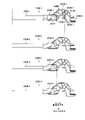
- FIG. 5 is a side view showing an example of different grade hammer assemblies in one embodiment of the present invention.
- a hammer assembly 200A shown in FIG. 5A is similar to the hammer assembly 200 shown in FIG.
- descriptions of features similar to those of the hammer assembly 200 of FIG. 4 will be omitted, and differences from the hammer assembly 200 will be mainly described.
- FIGS. when describing the same configuration as that of the first embodiment, reference will be made to FIGS. .
- the weight member 230A has a plate shape.
- the weight member 230A can be formed by sheet metal processing or the like.
- the shape of the weight member 230A is such that a trapezoidal 1-2 portion 280A is provided at the tip of a rectangular 1-1 portion 270A when viewed in the scale direction.
- a second portion 232A is provided on the side opposite to the 1-2 portion 280A with respect to the 1-1 portion 270A.
- the shape of the second portion 232A is a shape obtained by partially crushing the 1-1 portion 270A.
- FIG. 5 is merely an example, and a plate-like member having a shape other than that shown in FIG. 5 can be used as the weight member 230A.
- weight members 230A-1 to 230A-4 have the same shape.
- the weight members 230A-1 to 230A-4 are made of the same material.
- Weight members 230A-1 to 230A-4 each have the same mass as a result of the similar shape and material.
- weight member 230A-1 can be used with other hammer assemblies 200A-2 through 200A-4.
- the positions at which the weight members 230A-1 to 230A-4 are attached to the weight support members 250A-1 to 250A-4 are different. As a result, each of the hammer assemblies 200A-1 to 200A-4 has a different moment of inertia.
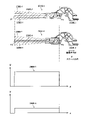
- FIG. 6 is a side view showing an example of different grade hammer assemblies in accordance with one embodiment of the present invention.
- Hammer assembly 200B shown in FIG. 6 is similar to hammer assembly 200 shown in FIG. It is different from the shape of -4.
- descriptions of features similar to those of the hammer assembly 200 of FIG. 4 will be omitted, and differences from the hammer assembly 200 will be mainly described.
- FIGS. when describing a configuration similar to that of other embodiments, reference will be made to FIGS. .
- the hammer assembly 200B rotates around the rotation center 222B.
- Hammer assemblies 200B-1 to 200B-4 are used according to the scale of the white key 100wB.
- hammer assemblies 200B-1 to 200B-4 are used according to the scale of the black key 100bB.
- different hammer assemblies 200B-1 are used among the plurality of white keys 100wB or the plurality of black keys 100bB. ⁇ 200B-4 is used.
- the positions where the weight members 230B-1 to 230B-4 are attached to the weight support members 250B-1 to 250B-4 are the same in the longitudinal direction of the key 100B. That is, the positions of the ends of the weight support members 250B-1 to 250B-4 in the longitudinal direction of the key 100B are the same. Further, the positions of the tips of the weight members 230B-1 to 230B-4 are the same in the longitudinal direction of the key 100B. On the other hand, the weight members 230B-1 to 230B-4 are different in diameter (thickness). In other words, the weight members 230B-1 to 230B-4 have different cross-sectional areas in cross sections perpendicular to the extending direction.
- the cross-sectional area of the weight member 230B-1 orthogonal to the extending direction of the weight member 230B-1 is substantially uniform in the extending direction.
- the cross-sectional area of the weight member 230B-4 orthogonal to the extending direction of the weight member 230B-4 is substantially uniform in the extending direction.
- the extending direction means a direction perpendicular to the cross section of the weight member 230B in the direction in which the cross-sectional area is minimized at an arbitrary position.
- the cross-sectional area of the weight member 230B-1 exposed from the weight support member 250B-1 perpendicular to the extending direction of the weight member 230B-1 is substantially uniform in the extending direction of the weight member 230B-1.
- the cross-sectional area of the weight member 230B-4 exposed from the weight support member 250B-4 perpendicular to the extending direction of the weight member 230B-4 is substantially uniform in the extending direction of the weight member 230B-4.
- the mass of the weight members 230B-1 to 230B-4 differs depending on the diameter (thickness) and cross-sectional area.
- the diameter (thickness) means the diameter when the cross-sectional shape of the weight member 230B is circular, and means the maximum width of the cross-sectional shape when the weight member 230B is not circular.
- the weight member 230B in this embodiment has a uniform cross-sectional area at a plurality of arbitrary points in the longitudinal direction of each of the weight members 230B-1 to 230B-4 (that is, a diameter at a plurality of arbitrary points in the longitudinal direction). is constant).
- each weight member 230B can be obtained by cutting out a predetermined length from one rod-shaped base.
- the cross section orthogonal to the extending direction of the weight member 230B can be said to be the cross section in the direction in which the cross-sectional area is minimized at positions other than the ends in the longitudinal direction of the weight member.
- the cross-sectional direction for evaluating the cross-sectional area is not always a fixed direction, but the cross-sectional direction in which the cross-sectional area is minimized at that position. That is, when the weight member 230B is curved, the direction of the cross section for evaluating the cross-sectional area differs depending on the position in the extension direction of the weight member 230B.
- the extending direction means a direction perpendicular to the cross section in the direction in which the cross-sectional area is minimized at any position of the weight member 230B.
- each of the weight members 230B-1 to 230B-4 has a substantially uniform cross-sectional area at arbitrary multiple points in the longitudinal direction. Therefore, in the longitudinal direction of the key 100B, the positions of the centers of gravity of the weight members 230B-1 to 230B-4 are substantially the same. For example, the distance between the center of gravity of the weight member 230B-1 and the center of rotation 222B-1 is the same as the distance between the center of gravity of the weight member 230B-2 and the center of rotation 222B-2.
- Weight members 230B-1 to 230B-4 have the same or similar shape as weight member 230 shown in FIG. That is, each of the weight members 230B-1 to 230B-4 has a first portion 231B and a second portion 232, like the weight member 230 shown in FIG.
- the positions of the centers of gravity of the weight members 230B-1 to 230B-4 are substantially the same in the longitudinal direction of the key 100B.
- the position of the center of gravity may be different.
- Weight members 230B-1 to 230B-4 having different positions of the center of gravity may have the same mass. Some or all of the materials of the weight members 230B-1 to 230B-4 may be different.
- FIG. 7 is a diagram showing the plane of rotation (or locus of rotation) of the center line of each weight member within the rotation range of the hammer assembly 200B for the weight members 230B-1 and 230B-4 having different masses in this embodiment. is. Centerlines 239B-1, 239B-4 of weight members 230B-1, 230B-4, respectively, are shown in dashed lines. The planes of rotation 238B-1, 238B-4 described by these centerlines when the hammer assembly 200B is rotated are indicated by diagonal hatching. When viewing the hammer assembly 200B in the scale direction, the surfaces of rotation 238B-1 and 238B-4 overlap and the outer edges of each of the surfaces of rotation 238B-1 and 238B-4 are substantially coincident. In other words, the surface of rotation 238B-1 and the surface of rotation 238B-4 have substantially the same shape.
- the tip P1 of the centerline 239B-1 and the tip P2 of the centerline 239B-4 substantially overlap (match).
- the tips P1 and P2 are the tips of the weight members 230B-1 and 230B-4 on the far side from the rotation centers 222B-1 and 222B-4. Similar to the above, when hammer assembly 200B is viewed in the scale direction, tip P3 of centerline 239B-1 and tip P4 of centerline 239B-4 substantially overlap (coincide).
- the tips P3 and P4 are the tips of the weight members 230B-1 and 230B-4 closer to the rotation center 222B-1.
- FIG. 7 shows a graph with the longitudinal direction of the key 100B as the x-axis and the linear density of the weight members 230B-1 and 230B-4 as the y-axis.
- Graph 290B-1 shows the linear density of weight member 230B-1 and graph 290B-4 shows the linear density of weight member 230B-4.
- the function for drawing graph 290B-1 is a function obtained by multiplying the function for drawing graph 290B-4 by a constant.
- FIG. 7 shows a configuration in which the graphs 290B-1 and 290B-4 of the regions corresponding to the weight members 230B-1 and 230B-4 are straight lines
- the configuration is not limited to this.
- these graphs may be curves.
- the hammer assembly 200B according to the present embodiment, by preparing weight members 230B with different cross-sectional areas, it is possible to realize a plurality of hammer assemblies 200B with different moments of inertia.
- the stoppers provided on the frame need to be arranged according to the shortest weight member.
- a stopper is commonly provided for a plurality of hammer assemblies. Therefore, when the stoppers are arranged as described above, the tip of the longest weight member is positioned beyond the stopper.
- the touch feeling balance between when the player hits the key 100B lightly and when the player hits the key 100B hard can be the same for different keys 100B. That is, the ratio of the touch feeling when the hammer assemblies 200B-1 and 200B-4 are hit lightly with the same force is substantially the same as the touch feeling ratio when the hammer assembly 200B-1 and 200B-4 is hit strongly with the same force. is. For example, when the player is weak with the same force, and the ratio of the weight that the player receives from the hammer assembly 200B-1 to the weight that the player receives from the hammer assembly 200B-4 is three times, the player hits hard with the same force. , the ratio of the above weights is three times.
- the above configuration achieves a balance of the static moment of inertia (static touch feeling) and a reaction force (dynamic touch feeling) generated when the rotation of the hammer assembly 200B caused by the moment of inertia is accelerated. ) can be made similar between the keys 100B belonging to each of the hammer assemblies 200B-1 and 200B-4.
- FIG. 8 is a diagram illustrating an example of a hammer assembly in accordance with one embodiment of the present invention.
- a hammer assembly 200D shown in FIG. 8 is similar to the hammer assembly 200 shown in FIG. 4, but differs from the hammer assembly 200 in that one hammer assembly 200D is provided with a plurality of weight members 230D.
- descriptions of features similar to those of the hammer assembly 200 of FIG. 4 will be omitted, and differences from the hammer assembly 200 will be mainly described.
- FIGS. when describing a configuration similar to that of other embodiments, reference will be made to FIGS. .
- the weight member 230D of the hammer assembly 200D has a first weight member 236D and a second weight member 237D.
- the hammer assembly 200D is rotatably attached to the shaft of the frame 500D by a bearing member 220D.
- the first weight member 236D and the second weight member 237D are provided on the side opposite to the portion (front end member 210D) where the key 100D acts on the hammer assembly 200D with respect to the rotation center 222D of the hammer assembly 200D.
- the rotation of the hammer assembly 200D causes the weight member 230D to rotate in the rotation direction (R direction) of the weight member 230D.
- the rotation surface of the first weight member 236D formed by this rotation overlaps the rotation surface of the second weight member 237D. That is, the first weight member 236D is provided within the rotation surface 238D of the second weight member 237D. In other words, the first weight member 236D and the second weight member 237D overlap vertically when the keyboard device 1D is played. However, the first weight member 236D and the second weight member 237D do not have to overlap vertically in this state.
- the first weight member 236D and the second weight member 237D are both rod-shaped (columnar) and have the same shape.
- the first weight member 236D and the second weight member 237D are fixed at the weight support member 250D.
- the direction in which the first weight member 236D pushes the upper stopper 430 is perpendicular to the longitudinal direction of the first weight member 236D. direction.
- the direction in which the second weight member 237D pushes the lower stopper 410D while the second weight member 237D is in contact with the lower stopper 410D It is a direction perpendicular to the longitudinal direction.
- first weight member 236D and the second weight member 237D are arranged so that the distance between them decreases from the weight support member 250D toward the tip of these weight portions. With such an arrangement, the first weight member 236D and the second weight member 237D can be firmly held by the weight support member 250D, and the area occupied by these weight members can be reduced near the tips thereof.
- the longitudinal direction of the first weight member 236D and the longitudinal direction of the second weight member 237D are not parallel to each other.
- the weight support member 250D is provided on the side of the main body member 240D. part protrudes downward.
- a rib 244D is provided to connect the weight support member 250D and the body member 240D.
- the front end member 210D has a connecting member 211D and a locking member 212D.
- the connecting member 211D connects between the body member 240D and the locking member 212D.
- the connection member 211D is plate-shaped.
- the locking member 212D is provided at the end of the connecting member 211D.
- the locking member 212D protrudes in the scale direction from the plate-like connecting member 211D.
- the locking member 212D of the front end member 210D slides against the inner wall portion of the hammer support portion 130w (see FIG. 3), thereby rotating the hammer assembly 200D in accordance with the movement of the key 100D.
- the shape of the inner wall of the hammer support portion 130w is designed according to the shape of the front end member 210D.
- each of the first weight member 236D and the second weight member 237D may have a shape in which part of the region covered by the weight support member 250D is crushed.
- the positions at which one or both of the first weight member 236D and the second weight member 237D are attached to the weight support member 250D are different, and the moment of inertia is different depending on the hammer assembly 200D.
- the maximum cross-sectional area of one or both of the first weight member 236D and the second weight member 237D may be different in different hammer assemblies 200, and the moment of inertia may be different depending on the hammer assembly 200D. .
- the first weight member 236D and the second weight member 237D are each rod-shaped, but the configuration is not limited to this. As will be described later, the first weight member 236D and the second weight member 237D do not have to be bar-shaped. If the first weight member 236D and the second weight member 237D are bar-shaped, they may be parallel. Also, as described above, the shape of the first weight member 236D may differ from the shape of the second weight member.
- the length of the hammer assembly 200D in the longitudinal direction of the key 100D can be shortened, so that the space of the keyboard device 1D in the depth direction can be reduced. can be done. Further, if the same weight member can be used for the first weight member 236D and the second weight member 237D, a keyboard device with low manufacturing cost and low work load can be realized.
- FIG. 9 is a diagram illustrating an example of a hammer assembly in accordance with one embodiment of the present invention.
- Hammer assembly 200E shown in FIG. 9 is similar to hammer assembly 200D shown in FIG. 8, but differs from hammer assembly 200D in that first weight member 236D and second weight member 237D are not rod-shaped.
- first weight member 236D and second weight member 237D are not rod-shaped.
- descriptions of features similar to those of the hammer assembly 200D of FIG. 8 are omitted, and differences from the hammer assembly 200D are mainly described.
- FIGS. when describing a configuration similar to that of other embodiments, reference will be made to FIGS. .
- the weight member 230E of the hammer assembly 200E has a flat first weight member 236E and a second weight member 237E.
- the first weight member 236E is provided within the rotation surface 238E of the second weight member 237E.
- the first weight member 236E and the second weight member 237E can be provided, for example, in recesses 242E surrounded by ribs 241E. Alternatively, an opening may be provided instead of the recess 242E, and the weight member may be provided in the opening.
- the length of the hammer assembly 200E in the longitudinal direction of the key 100E can be shortened, so that the space of the keyboard device 1E in the depth direction can be reduced. can.
- the first weight members 236D, 236E and the second weight members 237D, 237E are positioned relative to the rotation centers 222D, 222E of the hammer assemblies 200D, 200E, and the keys 100D, 100E are positioned relative to the hammer assembly 200D. , 200E (the front end members 210D and 210E), but the configuration is not limited to this.
- the portions of the first weight member 236D, the second weight member 237D, and the portion of the key 100D acting on the hammer assembly 200D may be provided on the same side of the pivot center 222D. That is, the key 100D may act on the hammer assembly 200D between the two weight members 236D, 237D and the pivot center 222D.
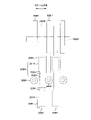
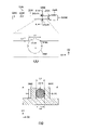
- FIG. 10 is a top view of the configuration with the hammer assembly attached to the frame in one embodiment of the present invention.
- Hammer assembly 200F shown in FIG. 10 is a cross-sectional view of hammer assembly 200-1 shown in FIG. 4 attached to frame 500 as viewed from above.
- FIGS. when describing a configuration similar to that of other embodiments, FIGS. .
- the hammer assembly 200F is attached to the shaft portion 520F.
- the shaft portion 520F extends in the scale direction (sometimes referred to as “first direction”).
- a plurality of hammer assemblies 200F are adjacent to each other in the scale direction.
- a plurality of ribs 590F are adjacent to each other in the scale direction.
- Ribs 590F and bosses 580F are provided between adjacent hammer assemblies 200F.
- a weight portion 230F provided on the hammer assembly 200F includes a first portion 231F and a second portion 232F. In the following description, at least one of the adjacent ribs 590F and bosses 580F may be referred to as "first member".
- the width of the second portion 232F is smaller than the width of the first portion 231F.
- the second portion 232F has a shape in which the first portion 231F is crushed in the scale direction.
- the first portion 231F does not face the first member (rib 590F and boss 580F), and the second portion 232F faces the first member.
- the first member is provided in a region sandwiched by the second portions 232F adjacent in the scale direction.
- the first member is not provided in the region sandwiched by the first portions 231F adjacent in the scale direction.
- the second portion 232F and the first member overlap, but the first portion 231F and the first member do not overlap. It should be noted that it is not necessary for all of the hammer assemblies 200F and the first member to satisfy the above relationship, and as long as the above relationship holds between at least some of the hammer assemblies 200F and the first member good.
- the ribs 590F and bosses 580F may be part of the frame 500F, that is, integrally formed with the frame 500F, or may be members fixed to the frame 500F by adhesion or the like.
- a boss 580F is provided at one end of the two ribs 590F.
- the bosses 580F may be provided at both ends of the two ribs 590F.
- the width of boss 580F is greater than the width of rib 590F.
- the weight support member 250F covers all of the second portion 232F and part of the first portion 231F.
- a portion of the weight member 230F between the adjacent ribs 590F has a shape that is crushed in the scale direction (first direction).
- the second portion 232F corresponding to the portion between the adjacent ribs 590F of the weight member 230F has a smaller thickness in the scale direction than the first portion 231F.
- ribs 590F for improving the strength of the frame 500F may be provided at positions adjacent to the keys 100F, and bosses 580F used for connection with other members may be provided. If the space for arranging the ribs 590F and the bosses 580F is restricted as the keyboard device 1F is miniaturized, it may become necessary to arrange the ribs 590F and the bosses 580F at positions adjacent to the keys 100F. Even in such a case, the above configuration can avoid interference with the key 100F while securing the weight of the weight member 230F.
- the rib 590F and the boss 580F adjacent to the weight member 230F in the scale direction correspond to the first member, but the configuration is not limited to this.
- the first member may be a member that sandwiches the weight member 230F in the vertical direction. That is, the weight member 230F may be provided between the first member and the second member in the vertical direction.
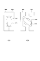
- FIG. 11 is a diagram showing an example of a weight member in one embodiment of the present invention.
- the weight member 230F has a first portion 231F and a second portion 232F.
- the first portion 231F is rod-shaped, specifically cylindrical.
- the second portion 232F is flat.
- the second portion 232F is formed by partially crushing the first portion 231F from both sides. Therefore, the width of the second portion 232F is smaller than the width of the first portion 231F in the D3 direction. In the D2 direction, the length of the second portion 232F is greater than the length of the first portion 231F.
- the cross-sectional area of the first portion 231F is substantially equal to the cross-sectional area of the second portion 232F.
- the second portion 232F is continuous from the upper end to the lower end in the D2 direction. In other words, the second portion 232F is different from a shape in which only a part of the region in the D2 direction has a concave portion or an opening, such as a stamp or a fastening hole.
- the mass per unit length of the first portion 231F and the mass per unit length of the second portion 232F are approximately equal.
- the main surface 2321F of the second portion 232F has a shape that is crushed by the press used for compression. There may be traces left behind.
- the side surface 2322F of the second portion 232F is a portion elongated as a result of the main surface 2321F being crushed during compression. Therefore, the surface condition of the main surface 2321F is different from the surface condition of the side surface 2322F.
- the second portion 232F having a shape in which the first portion 231 is crushed and having a relatively small thickness is provided at the end portion of the bar-shaped weight member 230F. As shown in FIG. 10, the second portion 232F is covered with a weight support member 250F.
- the width of the second portion 232F is the first greater than the width of portion 231F.
- the width of the boundary portion 233F in the D2 direction spreads from the first portion 231F toward the second portion 232F so as to draw a curve.
- the tip 2323F of the second portion 232F is curved.
- the curved shape of the distal end portion 2323F results from the formation of the second portion 232F by crushing the first portion 231F, which has a circular cross-sectional shape on a surface perpendicular to the D1 direction. Note that the above D3 direction corresponds to the scale direction in FIG.
- FIG. 11 illustrates the configuration in which the cross-sectional shape of the first portion 231F is circular
- the configuration is not limited to this.
- the cross-sectional shape of the first portion 231F may be flat.
- the second portion 232F has a configuration in which a portion of the first portion 231F is crushed in the scale direction, but the configuration is not limited to this.
- the end portion of the first portion 231F may have a shape (like a head of a nail) that is crushed in the longitudinal direction of the weight member 230F.
- FIGS. 12 to 14 are top views of the structure in which the hammer assembly is attached to the frame in one embodiment of the present invention.
- Hammer assemblies 200G (variant 1), 200H (variant 2), and 200J (variant 3) shown in FIGS. 12-14 are similar to hammer assembly 200F shown in FIG.
- the description of features similar to those of the hammer assembly 200F of FIG. 10 will be omitted, and mainly the differences from the hammer assembly 200F will be described.
- FIG. 10 or other drawings will be referred to, and the reference numerals shown in these figures will be followed by the letter "G" (Modification 1). ), “H” (Modification 2), and “J” (Modification 3).
- the modification shown in FIG. 12 is different from the hammer assembly 200F in that the rib 590G is provided with a guide 591G for restricting the movement of the hammer assembly 200G.
- the rib 590G is provided with a guide 591G projecting from the rib 590G toward the hammer assembly 200G.
- a guide 591G is provided on each of the adjacent ribs 590G. The guide 591G is in contact with the weight support member 250G, and slides relative to the weight support member 250G as the hammer assembly 200G rotates. That is, the guide 591G regulates the movement of the hammer assembly 200G in the scale direction.
- the guide 591G When viewed in the scale direction, the guide 591G overlaps the second portion 232G. In the scale direction, the width of the weight support member 250G in the region corresponding to the second portion 232G is smaller than the width of the weight support member 250G in the region corresponding to the first portion 231G.
- the guide 591G is in contact with the weight support member 250G in the region of the weight support member 250G where the width in the scale direction is relatively small.
- the guide 591G need only be slidable with respect to the weight support member 250G, and does not have to be in constant contact with the weight support member 250G.
- the second portion 232H is provided near the center of the weight member 230H, and the first portion 231H is provided in a region including the vicinity of both ends of the weight member 230H. That is, in the weight member 230H, the second portion 232H is sandwiched between the first portions 231H. Also, the boss 580H is provided at a position apart from the rib 590H in the longitudinal direction of the key 100H. When viewed in the scale direction, the second portion 232H is provided at a position overlapping the boss 580H.
- a weight support member 250H is provided to cover the first portion 231H, and a portion of the second portion 232H is exposed from the weight support member 250H. The weight support member 250H is provided so as to cover the boundary portion 233H between the first portion 231H and the second portion 232H.
- the configuration in which the boss 580H is provided at the position corresponding to the second portion 232H was exemplified, but the configuration is not limited to this.
- the second portion 232H is provided at a position that overlaps a member other than the boss 580H that may interfere with the hammer assembly 200H when viewed in the scale direction.
- the weight support member 250H does not have to cover the boundary portion 233H. That is, part of the first portion 231H may be exposed from the weight support member 250H.
- Modification 3 shown in FIG. 14 is similar to Modification 2 shown in FIG. 13, but differs from Modification 2 shown in FIG. 13 in that guides 591J are provided instead of bosses 580H in FIG. do.
- the guide 591J is fixed with respect to the frame 500J.
- the second portion 232J is provided at a position overlapping the guide 591J.
- the second portion 232J is provided between the two guides 591J.
- the guide 591J is in contact with the second portion 232J and slides relative to the second portion 232J as the hammer assembly 200J rotates. That is, the guide 591J regulates the movement of the hammer assembly 200J in the scale direction.
- the guide 591J only needs to be slidable with respect to the second portion 232J, and does not have to be in constant contact with the second portion 232J.
- the keyboard devices 1G, 1H, and 1J according to the above modified examples 1 to 3 can provide the same effects as the keyboard device 1F according to the fourth embodiment.
- FIG. 15 is a diagram showing an example of a weight member in one embodiment of the present invention.
- FIG. 15A is a top view of the weight member 230K.
- FIG. 15(B) is a cross-sectional view taken along line AA' of FIG. 15(A).
- the first portion 231K of the weight member 230K is provided with a groove 910K and a marker portion 920K.
- the groove 910K is recessed toward the inside of the first portion 231K from both ends of the first portion 231K in the D2 direction when viewed from above.
- groove 910K includes first groove 910-1K and second groove 910-2K.
- the first groove 910-1K is provided on the opposite side of the second groove 910-2K with respect to the weight member 230K.
- the groove 910K is provided in a part of the first portion 231K, most of the area of the first portion 231K, specifically 75% or more of the area, is an area where the groove 910K and the marker portion 920K are not provided. be. In this area, the cross-sectional shape perpendicular to the direction in which the first portion 231K extends is the same.
- a region surrounded by a dotted line in FIG. 15(A) is a partially enlarged view of a region in which the groove 910K is provided in the first portion 231K.
- the depth of the groove 910K in the D2 direction is L1.
- the width of the groove 910K in the D1 direction is L2.
- a bottom 911K of the groove 910K is planar.
- the shape of the bottom portion 911K can be appropriately adjusted according to the shape of the alignment member 990K described later.
- the bottom portion 911K may have an arc shape along the outer periphery of the cylinder.
- the groove 910K is used as an alignment for the weight member 230K when resin-molding the weight support member. Specifically, the position of the mold for resin molding and the position of the alignment member 990K are fixed. A weight member 230K is installed so as to be placed in position.
- FIG. 15A shows a state where the weight member 230K is positioned by the alignment member 990K.
- the shape of the alignment member 990K is cylindrical, and the diameter of the cylindrical circle is L3.
- L3 is 3 mm or more, 5 mm or more, or 7 mm or more. Considering the strength of the alignment member 990K, L3 is preferably 3 mm or more.
- the shape of the alignment member 990K is not limited to a cylindrical shape, and various other shapes can be applied.
- L1 is 0.2 mm or more, 0.3 mm or more, or 0.5 mm or more.
- L1 is preferably 0.2 mm or more.
- L2 is 2 mm or more, 3 mm or more, or 5 mm or more.
- L2 is preferably 2 mm or more.
- the marker part 920K is provided at the end in the D2 direction.
- the marker portion 920K is formed along the surface of the first portion 231K.
- the marker portion 920K may be formed by roughening the surface of the first portion 231K.
- the two are distinct in that the groove 910K provides a planar bottom 911K, whereas the marker portion 920K does not provide such a planar surface.
- the distance L4 between the facing alignment members 990K is smaller than the diameter L5 of the circular cross-sectional portion of the first portion 231K, and is provided at both ends of the first portion 231K in the D2 direction. is greater than the distance L6 between the two bottoms 911K.
- the bottom portion 911K contacts or faces the side wall of the alignment member 990K.
- FIG. 15A by arranging the weight member 230K so that the groove 910K is positioned between the two alignment members 990K, the orientation of the second portion 232K can be positioned in a certain direction. can.
- FIG. 16 is a diagram showing a process of resin-molding a weight supporting member to a weight member according to one embodiment of the present invention.
- FIG. 16A is a diagram showing a state in which the second portion 232K of the weight member 230K is sandwiched between molds 290K for resin-molding the weight support member 250K with the second portion 232K oriented properly.
- FIG. 16B is a diagram showing a state in which the weight member 230K is sandwiched between the molds 290K with the second portion 232K in an inappropriate orientation. As shown in FIG. 16B, when the weight member 230K is sandwiched between the molds 290K while the second portion 232K is greatly inclined from the normal state (the state shown in FIG.
- the molds 290K are There is a possibility that the second portion 232K will hit and damage the mold 290K or the second portion 232K.
- the alignment member 990K as shown in FIG. 15(A)
- the state shown in FIG. 16(B) can be avoided.
- an electronic piano is shown as an example of a keyboard device to which a hammer assembly is applied. Moreover, the configuration in which the hammer assembly is provided for the key is illustrated. However, the hammer assemblies of the above-described embodiments may be applied to devices other than electronic pianos or members other than keys of electronic pianos.
- a keyboard device comprises a frame, a first key, a second key, a first hammer assembly that rotates according to movement of the first key, and a hammer assembly that rotates according to movement of the second key. and a second hammer assembly that pivots with.
- the first hammer assembly includes: a first fixing member fixed to the frame; a first rotating member connected to the first fixing member so as to be rotatable about a first rotation center; a first weight member secured to the first pivot member.
- the second hammer assembly includes: a second fixed member fixed to the frame; a second rotating member connected to the second fixing member so as to be rotatable about a second rotation center; a second weight member having the same mass as the first weight member, fixed to the second rotating member.
- the distance between the center of gravity of the first weight member and the first rotation center is different from the distance between the center of gravity of the second weight member and the second rotation center.
- the first weight member and the second weight member may have the same shape.
- the first weight member and the second weight member may be made of the same material.
- the first weight member and the second weight member may be rod-shaped.
- Both the first key and the second key may be white keys or black keys.
- the first fixing member is the first shaft portion
- the second fixing member is the second shaft portion
- the first rotating member is the first bearing member
- the second rotating member is the second bearing It may be a member.
- the first bearing member may have a shape different from that of the second bearing member.
- a keyboard device comprises a frame, a first key, a second key, a first hammer assembly that rotates according to movement of the first key, and a hammer assembly that rotates according to movement of the second key. and a second hammer assembly that pivots with.
- the first hammer assembly includes: a first fixing member fixed to the frame; a first rotating member connected to the first fixing member so as to be rotatable about a first rotation center; a bar-shaped first weight member fixed to the first rotating member.
- the second hammer assembly includes: a second fixed member fixed to the frame; a second rotating member connected to the second fixing member so as to be rotatable about a second rotation center; a rod-shaped second weight member fixed to the second rotating member.
- the cross-sectional area of the first weight member orthogonal to the extending direction of the first weight member is substantially uniform in the extending direction of the first weight member, and the second weight member orthogonal to the extending direction of the second weight member. is substantially uniform in the extending direction of the second weight member, and the cross-sectional area of the first weight member is different from the cross-sectional area of the second weight member.
- a cross-sectional area of the first weight member exposed from the first weight support member perpendicular to the extension direction of the first weight member is substantially uniform in the extension direction of the first weight member, and the second weight support member.
- a cross-sectional area of the second weight member that is exposed through the second weight member perpendicular to the extending direction of the second weight member may be substantially uniform in the extending direction of the second weight member.
- the first weight member and the second weight member are viewed in the direction of the scale in which the first weight member and the second weight member are aligned, the first weight member on the far side from the first rotation center
- a first tip of the first center line and a second tip of the second center line of the second weight member farther from the second rotation center overlap each other, and the second tip of the second weight member on the side closer to the first rotation center overlaps.
- a third tip of the first center line and a fourth tip of the second center line near the second rotation center may overlap.
- the first center line is drawn by the rotation of the first hammer assembly.
- a first plane of rotation and a second plane of rotation described by the second centerline due to rotation of the second hammer assembly may coincide.
- the line in the region corresponding to the first weight member A first graph showing the density and a second graph showing the linear density of the region corresponding to the second weight member may have a relationship in which one of them is multiplied by a constant.
- the distance between the center of gravity of the first weight member and the first center of rotation may be the same as the distance between the center of gravity of the second weight member and the second center of rotation.
- the cross-sectional area of the first weight member is the cross-sectional area in the direction in which the cross-sectional area is minimized at a position other than the end portion in the longitudinal direction of the first weight member
- the cross-sectional area of the second weight member is The cross-sectional area may be the cross-sectional area in the direction in which the cross-sectional area is minimized at a position other than the end portion in the longitudinal direction of the second weight member.
- the first weight member and the second weight member may have different masses.
- the first weight member and the second weight member may be made of the same material.
- Both the first key and the second key may be white keys or black keys.
- the first fixed member may be a shaft portion, and the first rotating member may be a bearing member.
- a keyboard device has a frame, a key, and a hammer assembly that rotates according to movement of the key.
- the hammer assembly includes a fixed member fixed to the frame, a rotating member connected to the fixed member so as to be rotatable about a rotating shaft, and a first weight attached to the rotating member. and a second weight member attached to the pivot member.
- the first weight member is provided in a pivot plane of the second weight member, and both the first weight member and the second weight member are arranged such that the key is positioned relative to the pivot axis to the hammer assembly. It is provided on the same side or the opposite side as the part acting on the
- the first weight member and the second weight member may each be rod-shaped.
- the first weight member and the second weight member may be arranged non-parallel.
- the shape of the first weight member may be the same as the shape of the second weight member.
- the fixed member may be a shaft portion, and the rotating member may be a bearing member.
Landscapes
- Physics & Mathematics (AREA)
- Engineering & Computer Science (AREA)
- Acoustics & Sound (AREA)
- Multimedia (AREA)
- Electrophonic Musical Instruments (AREA)
Abstract
Description
[1-1.鍵盤装置の構成]
図1は、第1実施形態における鍵盤装置の構成を示す図である。鍵盤装置1は、ユーザ(演奏者)の押鍵に応じて発音する、例えば電子ピアノなどの電子鍵盤楽器である。鍵盤装置1は、外部の音源装置を制御するための制御データ(例えば、MIDI)を、押鍵に応じて出力する鍵盤型のコントローラであってもよい。この場合には、鍵盤装置1は、音源装置を有していなくてもよい。
図3は、第1実施形態における筐体内部の構成を側面から見た場合の説明図である。以下の説明では、白鍵100wを例示して説明するが、本実施形態に係るハンマアセンブリ200は黒鍵100bに用いることもでき、白鍵100wに用いられるハンマアセンブリ200に限定されない。図3に示すように、筐体90の内部において、鍵盤アセンブリ10及びスピーカ80が配置されている。スピーカ80は、鍵盤アセンブリ10の奥側に配置されている。このスピーカ80は、押鍵に応じた音を筐体90の上方及び下方に向けて出力するように配置されている。下方に出力される音は、筐体90の下面側から外部に進む。一方、上方に出力される音は筐体90の内部から鍵盤アセンブリ10の内部の空間を通過して、外観部PVにおける白鍵100wの隣接間の隙間又は白鍵100wと筐体90との隙間から外部に進む。
図4は、本発明の一実施形態における、グレードの異なるハンマアセンブリの一例を示す側面図である。図4に示すように、ハンマアセンブリ200は、前端部材210、軸受け部材220、ウェイト部材230、本体部材240、ウェイト支持部材250、及びマーカ部材260を備える。図4では、4種類のハンマアセンブリ200が示されている。ハンマアセンブリ200の種類によってハンマアセンブリ200-1、200-2、200-3、200-4が示されている。以下の説明において、各々のハンマアセンブリ200を区別して説明をする場合、ハンマアセンブリ200及びハンマアセンブリ200を構成する各部材の符号の後に「-1」等の枝番号を付して説明する。一方、各々のハンマアセンブリ200を区別する必要がない場合、当該枝番号を付さずに、単にハンマアセンブリ200と表現する。
図5を用いて、第1実施形態の変形例について説明する。図5は、本発明の一実施形態における、グレードの異なるハンマアセンブリの一例を示す側面図である。図5(A)に示すハンマアセンブリ200Aは、図4に示すハンマアセンブリ200と類似しているが、ウェイト部材230Aの形状がウェイト部材230の形状と異なる点において、ハンマアセンブリ200と相違する。以下の説明において、図4のハンマアセンブリ200と同様の特徴については説明を省略し、主にハンマアセンブリ200と相違する点について説明する。なお、以下の説明において、第1実施形態と同様の構成について説明をする場合、図1~図4を参照し、これらの図に示された符号の後にアルファベット“A”を付して説明する。
[2-1.ハンマアセンブリ200Bの構成]
図6を用いて、第2実施形態について説明する。図6は、本発明の一実施形態における、グレードの異なるハンマアセンブリの一例を示す側面図である。図6に示すハンマアセンブリ200Bは、図4に示すハンマアセンブリ200と類似しているが、ハンマアセンブリ200Bのウェイト部材230B-1~230B-4の形状がハンマアセンブリ200のウェイト部材230-1~230-4の形状と相違する。以下の説明において、図4のハンマアセンブリ200と同様の特徴については説明を省略し、主にハンマアセンブリ200と相違する点について説明する。なお、以下の説明において、他の実施形態と同様の構成について説明をする場合、図1~図5を参照し、これらの図に示された符号の後にアルファベット“B”を付して説明する。
[3-1.ハンマアセンブリ200Dの構成]
図8を用いて、第3実施形態について説明する。図8は、本発明の一実施形態におけるハンマアセンブリの一例を示す図である。図8に示すハンマアセンブリ200Dは、図4に示すハンマアセンブリ200と類似しているが、1つのハンマアセンブリ200Dに複数のウェイト部材230Dが設けられている点において、ハンマアセンブリ200と相違する。以下の説明において、図4のハンマアセンブリ200と同様の特徴については説明を省略し、主にハンマアセンブリ200と相違する点について説明する。なお、以下の説明において、他の実施形態と同様の構成について説明をする場合、図1~図7を参照し、これらの図に示された符号の後にアルファベット“D”を付して説明する。
図9を用いて、第3実施形態の変形例について説明する。図9は、本発明の一実施形態におけるハンマアセンブリの一例を示す図である。図9に示すハンマアセンブリ200Eは、図8に示すハンマアセンブリ200Dと類似しているが、第1ウェイト部材236D及び第2ウェイト部材237Dの形状が棒状ではない点において、ハンマアセンブリ200Dと相違する。以下の説明において、図8のハンマアセンブリ200Dと同様の特徴については説明を省略し、主にハンマアセンブリ200Dと相違する点について説明する。なお、以下の説明において、他の実施形態と同様の構成について説明をする場合、図1~図8を参照し、これらの図に示された符号の後にアルファベット“E”を付して説明する。
[4-1.ハンマアセンブリ200Fの構成]
図10を用いて、第4実施形態について説明する。図10は、本発明の一実施形態において、ハンマアセンブリがフレームに取り付けられた状態における構成を上方から見た図である。図10に示すハンマアセンブリ200Fは、図4に示すハンマアセンブリ200-1がフレーム500に取り付けられた状態の上方から見た断面図である。以下の説明において、図4のハンマアセンブリ200と同様の特徴については説明を省略し、第1実施形態では説明していない点について説明する。なお、以下の説明において、他の実施形態と同様の構成について説明をする場合、図1~図9を参照し、これらの図に示された符号の後にアルファベット“F”を付して説明する。
図11は、本発明の一実施形態におけるウェイト部材の一例を示す図である。図11(A)~(C)に示すように、ウェイト部材230Fは第1部分231F及び第2部分232Fを有する。第1部分231Fは棒状、具体的には円柱状である。第2部分232Fは平板状である。第2部分232Fは第1部分231Fの一部が両側から潰されることで形成されている。したがって、D3方向において、第2部分232Fの幅は第1部分231Fの幅より小さい。D2方向において、第2部分232Fの長さは第1部分231Fの長さより大きい。また、ウェイト部材230Fの長手方向(D1方向)に対して直交する断面において、第1部分231Fの断面積は第2部分232Fの断面積とほぼ等しい。また、第2部分232Fは、D2方向に上端から下端まで連続している。つまり、第2部分232Fは、刻印や締結孔のようにD2方向に一部の領域だけに凹部又は開口がある形状とは異なる。
図12~図14を用いて、第4実施形態の変形例について説明する。図12~図14は、それぞれ本発明の一実施形態において、ハンマアセンブリがフレームに取り付けられた状態における構成を上方から見た図である。図12~図14に示すハンマアセンブリ200G(変形例1)、200H(変形例2)、200J(変形例3)は、図10に示すハンマアセンブリ200Fと類似している。以下の変形例の説明において、図10のハンマアセンブリ200Fと同様の特徴については説明を省略し、主にハンマアセンブリ200Fと相違する点について説明する。なお、以下の説明において、第4実施形態と同様の構成について説明をする場合、図10又はその他の図面を参照し、これらの図に示された符号の後にそれぞれアルファベット“G”(変形例1)、“H”(変形例2)、“J”(変形例3)を付して説明する。
図12に示す変形例は、リブ590Gにハンマアセンブリ200Gの動作を規制するガイド591Gが設けられている点において、ハンマアセンブリ200Fと相違する。図12に示すように、リブ590Gには、リブ590Gからハンマアセンブリ200Gに向かって突出するガイド591Gが設けられている。ガイド591Gは隣接するリブ590Gの各々に設けられている。ガイド591Gはウェイト支持部材250Gに接しており、ハンマアセンブリ200Gの回動動作に伴い、ウェイト支持部材250Gに対して摺動する。つまり、ガイド591Gは、ハンマアセンブリ200Gのスケール方向の移動を規制する。スケール方向に見て、ガイド591Gは第2部分232Gと重なっている。スケール方向において、第2部分232Gに対応する領域のウェイト支持部材250Gの幅は、第1部分231Gに対応する領域のウェイト支持部材250Gの幅よりも小さい。ガイド591Gは、ウェイト支持部材250Gのうち、スケール方向の幅が相対的に小さい領域のウェイト支持部材250Gに接している。なお、ガイド591Gはウェイト支持部材250Gに対して摺動可能であればよく、常に接していなくてもよい。
図13に示す変形例2では、第2部分232Hがウェイト部材230Hの中央付近に設けられており、第1部分231Hがウェイト部材230Hの両端付近を含む領域に設けられている。つまり、ウェイト部材230Hでは、第2部分232Hは第1部分231Hに挟まれている。また、鍵100Hの長手方向において、ボス580Hがリブ590Hから離れた位置に設けられている。スケール方向に見て、第2部分232Hはボス580Hと重なる位置に設けられている。ウェイト支持部材250Hは第1部分231Hを覆うように設けられており、第2部分232Hの一部はウェイト支持部材250Hから露出されている。ウェイト支持部材250Hは第1部分231Hと第2部分232Hとの境界部分233Hを覆うように設けられている。
図14に示す変形例3は、図13に示す変形例2と類似しているが、図13のボス580Hの代わりにガイド591Jが設けられている点において、図13に示す変形例2と相違する。ガイド591Jはフレーム500Jに対して固定されている。スケール方向に見て、第2部分232Jはガイド591Jと重なる位置に設けられている。スケール方向において、第2部分232Jは2つのガイド591Jの間に設けられている。ガイド591Jは第2部分232Jに接しており、ハンマアセンブリ200Jの回動動作に伴い、第2部分232Jに対して摺動する。つまり、ガイド591Jは、ハンマアセンブリ200Jのスケール方向の移動を規制する。なお、ガイド591Jは第2部分232Jに対して摺動可能であればよく、常に接していなくてもよい。
[5-1.ウェイト部材230Kの構成]
図15及び図16を用いて、第5実施形態について説明する。図15は、本発明の一実施形態におけるウェイト部材の一例を示す図である。図15(A)は、ウェイト部材230Kの上面図である。図15(B)は、図15(A)のA-A’線の断面図である。
Claims (33)
- フレームと、
第1部材と、
鍵と、
前記鍵の動きに応じて回動するハンマアセンブリと、を有し、
前記ハンマアセンブリは、
前記フレームに対して回動軸を中心に回動可能に接続された回動部材と、
前記回動部材に取り付けられ、第1部分及び第2部分を備えたウェイト部材と、を有し、
前記回動軸が延びる第1方向において、前記第2部分は前記第1部材と対面し、
前記第1方向において、前記第2部分の厚みは前記第1部分の厚みより小さく、
前記ウェイト部材の回動方向において、前記第2部分の長さは前記第1部分の長さより大きい鍵盤装置。 - フレームと、
第1部材と、
鍵と、
前記鍵の動きに応じて回動するハンマアセンブリと、を有し、
前記ハンマアセンブリは、
前記フレームに対して回動軸を中心に回動可能に接続された回動部材と、
前記回動部材に取り付けられ、第1部分及び第2部分を備えたウェイト部材と、を有し、
前記回動軸が延びる第1方向において、前記第2部分は前記第1部材と対面し、
前記第2部分は、前記第1部分が前記第1方向に潰れた形状である鍵盤装置。 - 前記ハンマアセンブリは複数設けられ、
前記第1部材は、
前記フレームの一部又は前記フレームに固定された部材であり、
隣接する前記ハンマアセンブリの間に設けられている、請求項1又は2に記載の鍵盤装置。 - 前記第1部材はボスである、請求項1乃至3のいずれか一に記載の鍵盤装置。
- 前記第1部材はリブである、請求項1乃至3のいずれか一に記載の鍵盤装置。
- 前記第1部材は前記ハンマアセンブリの前記第1方向の移動を規制するガイドである、請求項1乃至3のいずれか一に記載の鍵盤装置。
- 前記ウェイト部材は棒状であり、前記第2部分は棒状の端部である、請求項1乃至6のいずれか一に記載の鍵盤装置。
- 前記ウェイト部材は棒状であり、前記第2部分は前記回動部材に覆われている、請求項1乃至7のいずれか一に記載の鍵盤装置。
- 前記鍵は、第1鍵及び第2鍵を含み、
前記ハンマアセンブリは、第1ハンマアセンブリ及び第2ハンマアセンブリを含み、
前記第1ハンマアセンブリは、前記第1鍵の動きに応じて回動し、
前記第2ハンマアセンブリは、前記第2鍵の動きに応じて回動し、
前記第1ハンマアセンブリは、
前記フレームに固定された第1固定部材と、
前記第1固定部材に対して第1回動中心を中心に回動可能に接続された第1回動部材と、
前記第1回動部材に固定された第1ウェイト部材と、を有し、
前記第2ハンマアセンブリは、
前記フレームに固定された第2固定部材と、
前記第2固定部材に対して第2回動中心を中心に回動可能に接続された第2回動部材と、
前記第2回動部材に固定された、前記第1ウェイト部材と同じ質量の第2ウェイト部材と、を有し、
前記第1ウェイト部材の重心と前記第1回動中心との距離は、前記第2ウェイト部材の重心と前記第2回動中心との距離と異なる、請求項1に記載の鍵盤装置。 - 前記第1ウェイト部材と前記第2ウェイト部材とは、同一形状である、請求項9に記載の鍵盤装置。
- 前記第1ウェイト部材と前記第2ウェイト部材とは、同一材料である、請求項9又は2に記載の鍵盤装置。
- 前記第1ウェイト部材と前記第2ウェイト部材とは、棒状である、請求項9乃至11のいずれか一に記載の鍵盤装置。
- 前記第1鍵及び前記第2鍵の両方は、白鍵又は黒鍵である、請求項9乃至12のいずれか一に記載の鍵盤装置。
- 前記第1固定部材が第1軸部であり、前記第2固定部材が第2軸部であり、前記第1回動部材が第1軸受け部材であり、前記第2回動部材が第2軸受け部材である、請求項9乃至13のいずれか一に記載の鍵盤装置。
- 前記第1軸受け部材は、前記第2軸受け部材と異なる形状である、請求項14に記載の鍵盤装置。
- 前記鍵は、第1鍵及び第2鍵を含み、
前記ハンマアセンブリは、第1ハンマアセンブリ及び第2ハンマアセンブリを含み、
前記第1ハンマアセンブリは、前記第1鍵の動きに応じて回動し、
前記第2ハンマアセンブリは、前記第2鍵の動きに応じて回動し、
前記第1ハンマアセンブリは、
前記フレームに固定された第1固定部材と、
前記第1固定部材に対して第1回動中心を中心に回動可能に接続された第1回動部材と、
前記第1回動部材に固定された棒状の第1ウェイト部材と、を有し、
前記第2ハンマアセンブリは、
前記フレームに固定された第2固定部材と、
前記第2固定部材に対して第2回動中心を中心に回動可能に接続された第2回動部材と、
前記第2回動部材に固定された、棒状の第2ウェイト部材と、を有し、
前記第1ウェイト部材の延伸方向に直交する前記第1ウェイト部材の断面積は前記第1ウェイト部材の延伸方向に略均一であり、前記第2ウェイト部材の延伸方向に直交する前記第2ウェイト部材の断面積は前記第2ウェイト部材の延伸方向に略均一であり、前記第1ウェイト部材の断面積は前記第2ウェイト部材の断面積と異なる、請求項1に記載の鍵盤装置。 - 前記第1ウェイト部材の一方の端部を覆って支持する第1ウェイト支持部材と、
前記第2ウェイト部材の一方の端部を覆って支持する第2ウェイト支持部材と、をさらに有し、
前記第1ウェイト支持部材から露出された前記第1ウェイト部材の延伸方向に直交する前記第1ウェイト部材の断面積は、前記第1ウェイト部材の延伸方向に略均一であり、
前記第2ウェイト支持部材から露出された前記第2ウェイト部材の延伸方向に直交する前記第2ウェイト部材の断面積は、前記第2ウェイト部材の延伸方向に略均一である、請求項16に記載の鍵盤装置。 - 前記第1ウェイト部材と前記第2ウェイト部材とが並ぶスケール方向に前記第1ウェイト部材と前記第2ウェイト部材とを見た場合、
前記第1回動中心から遠い側の前記第1ウェイト部材の第1中心線の第1先端と前記第2回動中心から遠い側の前記第2ウェイト部材の第2中心線の第2先端とは重なっており、
前記第1回動中心に近い側の前記第1中心線の第3先端と前記第2回動中心に近い側の前記第2中心線の第4先端とは重なる、請求項16又は17に記載の鍵盤装置。 - 前記第1ウェイト部材と前記第2ウェイト部材とが並ぶスケール方向に前記第1ウェイト部材と前記第2ウェイト部材とを見た場合、
前記第1ハンマアセンブリの回動によって前記第1中心線が描く第1回転面と、前記第2ハンマアセンブリの回動によって前記第2中心線が描く第2回転面とは一致する、請求項18に記載の鍵盤装置。 - 前記第1鍵及び前記第2鍵の長手方向をx軸、前記第1ウェイト部材及び前記第2ウェイト部材の線密度をy軸としたグラフにおいて、
前記第1ウェイト部材に対応する領域の前記線密度を示す第1グラフと、前記第2ウェイト部材に対応する領域の前記線密度を示す第2グラフとは、一方を定数倍した関係にある、請求項18に記載の鍵盤装置。 - 前記第1ウェイト部材の重心と前記第1回動中心との距離は、前記第2ウェイト部材の重心と前記第2回動中心との距離と同じである、請求項16乃至19のいずれか一に記載の鍵盤装置。
- 前記第1ウェイト部材の断面積は、前記第1ウェイト部材の長手方向における端部以外の位置において断面積が最小になる方向の断面における断面積であり、前記第2ウェイト部材の断面積は、前記第2ウェイト部材の長手方向における端部以外の位置において断面積が最小になる方向の断面における断面積である、請求項16乃至21のいずれか一に記載の鍵盤装置。
- 前記第1ウェイト部材と前記第2ウェイト部材とは、質量が異なる、請求項16乃至22のいずれか一に記載の鍵盤装置。
- 前記第1ウェイト部材と前記第2ウェイト部材とは、同一材料である、請求項16乃至23のいずれか一に記載の鍵盤装置。
- 前記第1鍵及び前記第2鍵の両方は、白鍵又は黒鍵である、請求項16乃至24のいずれか一に記載の鍵盤装置。
- 前記第1固定部材が軸部であり、前記第1回動部材が軸受け部材である、請求項16乃至25のいずれか一に記載の鍵盤装置。
- 前記ハンマアセンブリは、前記フレームに固定された固定部材を有し、
前記回動部材は、前記固定部材に対して前記回動軸を中心に回動可能に接続され、
前記ウェイト部材は、
前記回動部材に取り付けられた第1ウェイト部材と、
前記回動部材に取り付けられた第2ウェイト部材と、を有し、
前記第1ウェイト部材は、前記第2ウェイト部材の回動面内に設けられており、
前記第1ウェイト部材及び前記第2ウェイト部材は共に、前記回動軸に対して前記鍵が前記ハンマアセンブリに作用する部分と同じ側又は逆側に設けられている、請求項1に記載の鍵盤装置。 - 前記第1ウェイト部材及び前記第2ウェイト部材は、それぞれ棒状である、請求項27に記載の鍵盤装置。
- 前記第1ウェイト部材と前記第2ウェイト部材とは非平行に配置されている、請求項27又は28に記載の鍵盤装置。
- 前記第1ウェイト部材の形状は、前記第2ウェイト部材の形状と同じである、請求項27乃至29のいずれか一に記載の鍵盤装置。
- 前記固定部材が軸部であり、前記回動部材が軸受け部材である、請求項27乃至30のいずれか一に記載の鍵盤装置。
- 前記ウェイト部材は、前記第1部分に底部が平面状である溝を有する、請求項1に記載の鍵盤装置。
- 前記溝は、第1溝及び第2溝を含み、
前記第1溝は、前記ウェイト部材を基準として、前記第2溝の反対側に設けられている、請求項32に記載の鍵盤装置。
Priority Applications (5)
| Application Number | Priority Date | Filing Date | Title |
|---|---|---|---|
| CN202280023331.XA CN117099153A (zh) | 2021-03-22 | 2022-01-12 | 键盘装置 |
| DE112022001750.3T DE112022001750T5 (de) | 2021-03-22 | 2022-01-12 | Klaviaturvorrichtung |
| JP2023508654A JP7559928B2 (ja) | 2021-03-22 | 2022-01-12 | 鍵盤装置 |
| US18/465,453 US20240046905A1 (en) | 2021-03-22 | 2023-09-12 | Keyboard apparatus |
| JP2024161379A JP7758121B2 (ja) | 2021-03-22 | 2024-09-18 | 鍵盤装置 |
Applications Claiming Priority (8)
| Application Number | Priority Date | Filing Date | Title |
|---|---|---|---|
| JP2021047714 | 2021-03-22 | ||
| JP2021-047712 | 2021-03-22 | ||
| JP2021047717 | 2021-03-22 | ||
| JP2021-047714 | 2021-03-22 | ||
| JP2021-047717 | 2021-03-22 | ||
| JP2021047713 | 2021-03-22 | ||
| JP2021-047713 | 2021-03-22 | ||
| JP2021047712 | 2021-03-22 |
Related Child Applications (1)
| Application Number | Title | Priority Date | Filing Date |
|---|---|---|---|
| US18/465,453 Continuation US20240046905A1 (en) | 2021-03-22 | 2023-09-12 | Keyboard apparatus |
Publications (1)
| Publication Number | Publication Date |
|---|---|
| WO2022201751A1 true WO2022201751A1 (ja) | 2022-09-29 |
Family
ID=83396827
Family Applications (1)
| Application Number | Title | Priority Date | Filing Date |
|---|---|---|---|
| PCT/JP2022/000723 Ceased WO2022201751A1 (ja) | 2021-03-22 | 2022-01-12 | 鍵盤装置 |
Country Status (4)
| Country | Link |
|---|---|
| US (1) | US20240046905A1 (ja) |
| JP (2) | JP7559928B2 (ja) |
| DE (1) | DE112022001750T5 (ja) |
| WO (1) | WO2022201751A1 (ja) |
Citations (2)
| Publication number | Priority date | Publication date | Assignee | Title |
|---|---|---|---|---|
| JPH11265177A (ja) * | 1998-03-16 | 1999-09-28 | Casio Comput Co Ltd | 鍵盤装置 |
| JP2018163192A (ja) * | 2017-03-24 | 2018-10-18 | ヤマハ株式会社 | ハンマアセンブリ、鍵盤楽器およびハンマ |
Family Cites Families (6)
| Publication number | Priority date | Publication date | Assignee | Title |
|---|---|---|---|---|
| JP2002099280A (ja) | 2000-09-22 | 2002-04-05 | Yamaha Corp | 鍵盤楽器及び鍵盤楽器の調整方法 |
| JP5963415B2 (ja) | 2011-09-30 | 2016-08-03 | 株式会社河合楽器製作所 | 電子鍵盤楽器のハンマー装置 |
| JP2018081137A (ja) | 2016-11-14 | 2018-05-24 | ヤマハ株式会社 | 鍵盤装置 |
| JP6780768B2 (ja) | 2017-03-24 | 2020-11-04 | ヤマハ株式会社 | 鍵盤装置 |
| JP6795022B2 (ja) | 2018-10-18 | 2020-12-02 | カシオ計算機株式会社 | 鍵盤楽器 |
| JP7346949B2 (ja) | 2019-07-08 | 2023-09-20 | ヤマハ株式会社 | 鍵盤、鍵盤用部品 |
-
2022
- 2022-01-12 WO PCT/JP2022/000723 patent/WO2022201751A1/ja not_active Ceased
- 2022-01-12 JP JP2023508654A patent/JP7559928B2/ja active Active
- 2022-01-12 DE DE112022001750.3T patent/DE112022001750T5/de active Pending
-
2023
- 2023-09-12 US US18/465,453 patent/US20240046905A1/en active Pending
-
2024
- 2024-09-18 JP JP2024161379A patent/JP7758121B2/ja active Active
Patent Citations (2)
| Publication number | Priority date | Publication date | Assignee | Title |
|---|---|---|---|---|
| JPH11265177A (ja) * | 1998-03-16 | 1999-09-28 | Casio Comput Co Ltd | 鍵盤装置 |
| JP2018163192A (ja) * | 2017-03-24 | 2018-10-18 | ヤマハ株式会社 | ハンマアセンブリ、鍵盤楽器およびハンマ |
Also Published As
| Publication number | Publication date |
|---|---|
| JP2024166375A (ja) | 2024-11-28 |
| JPWO2022201751A1 (ja) | 2022-09-29 |
| JP7559928B2 (ja) | 2024-10-02 |
| US20240046905A1 (en) | 2024-02-08 |
| JP7758121B2 (ja) | 2025-10-22 |
| DE112022001750T5 (de) | 2024-01-11 |
Similar Documents
| Publication | Publication Date | Title |
|---|---|---|
| US7332663B2 (en) | Keyboard apparatus | |
| US7465863B2 (en) | Keyboard apparatus | |
| JP6780768B2 (ja) | 鍵盤装置 | |
| US10885884B2 (en) | Pivot member and keyboard apparatus | |
| US10304422B2 (en) | Support assembly and keyboard apparatus | |
| JP7758121B2 (ja) | 鍵盤装置 | |
| JP6511903B2 (ja) | サポートアセンブリ及び鍵盤装置 | |
| JP2020095062A (ja) | 鍵盤装置 | |
| JP2017027053A (ja) | サポートアセンブリ及び鍵盤装置 | |
| JP2020060604A (ja) | 電子鍵盤楽器、及び電子鍵盤装置 | |
| CN117099153A (zh) | 键盘装置 | |
| WO2018174161A1 (ja) | ハンマアセンブリ、鍵盤楽器およびハンマ | |
| JP2023107580A (ja) | 鍵盤ユニット | |
| WO2016152501A1 (ja) | サポートアセンブリおよび鍵盤装置 | |
| WO2018174261A1 (ja) | ハンマアセンブリおよび鍵盤装置 | |
| US20240428763A1 (en) | Keyboard device and electronic musical instrument | |
| CN222028791U (zh) | 键盘单元 | |
| JP6707942B2 (ja) | 回動機構および鍵盤装置 | |
| JP6707832B2 (ja) | サポートアセンブリ | |
| JP3204564U (ja) | サポートアセンブリおよび鍵盤装置 | |
| JP6465150B2 (ja) | サポートアセンブリおよび鍵盤装置 | |
| WO2017065262A1 (ja) | 鍵盤装置 | |
| JP6561677B2 (ja) | 鍵盤装置及びサポート部材 | |
| JP3722020B2 (ja) | 鍵盤装置 | |
| WO2022113350A1 (ja) | 鍵盤装置 |
Legal Events
| Date | Code | Title | Description |
|---|---|---|---|
| 121 | Ep: the epo has been informed by wipo that ep was designated in this application |
Ref document number: 22774556 Country of ref document: EP Kind code of ref document: A1 |
|
| ENP | Entry into the national phase |
Ref document number: 2023508654 Country of ref document: JP Kind code of ref document: A |
|
| WWE | Wipo information: entry into national phase |
Ref document number: 202280023331.X Country of ref document: CN |
|
| WWE | Wipo information: entry into national phase |
Ref document number: 112022001750 Country of ref document: DE |
|
| 122 | Ep: pct application non-entry in european phase |
Ref document number: 22774556 Country of ref document: EP Kind code of ref document: A1 |