WO2022201735A1 - 情報提示装置 - Google Patents
情報提示装置 Download PDFInfo
- Publication number
- WO2022201735A1 WO2022201735A1 PCT/JP2022/000208 JP2022000208W WO2022201735A1 WO 2022201735 A1 WO2022201735 A1 WO 2022201735A1 JP 2022000208 W JP2022000208 W JP 2022000208W WO 2022201735 A1 WO2022201735 A1 WO 2022201735A1
- Authority
- WO
- WIPO (PCT)
- Prior art keywords
- image
- bird
- eye view
- construction site
- blind spot
- Prior art date
Links
- 238000010276 construction Methods 0.000 claims abstract description 92
- 238000012876 topography Methods 0.000 claims abstract description 48
- 238000000034 method Methods 0.000 claims abstract description 38
- 238000003384 imaging method Methods 0.000 claims abstract description 25
- 240000004050 Pentaglottis sempervirens Species 0.000 claims description 230
- 235000004522 Pentaglottis sempervirens Nutrition 0.000 claims description 230
- 230000002194 synthesizing effect Effects 0.000 claims description 30
- 238000012545 processing Methods 0.000 claims description 23
- 239000000203 mixture Substances 0.000 abstract description 2
- 239000002131 composite material Substances 0.000 abstract 1
- 238000010586 diagram Methods 0.000 description 26
- 238000004364 calculation method Methods 0.000 description 20
- 238000003702 image correction Methods 0.000 description 8
- 238000001514 detection method Methods 0.000 description 6
- 230000006870 function Effects 0.000 description 6
- 238000013461 design Methods 0.000 description 5
- 238000004891 communication Methods 0.000 description 4
- 230000015572 biosynthetic process Effects 0.000 description 3
- 238000003786 synthesis reaction Methods 0.000 description 3
- 238000009434 installation Methods 0.000 description 2
- 230000009286 beneficial effect Effects 0.000 description 1
- 239000004035 construction material Substances 0.000 description 1
- 238000013135 deep learning Methods 0.000 description 1
- 238000005516 engineering process Methods 0.000 description 1
- 230000003287 optical effect Effects 0.000 description 1
- 239000000047 product Substances 0.000 description 1
- 239000013589 supplement Substances 0.000 description 1
Images


Classifications
-
- E—FIXED CONSTRUCTIONS
- E02—HYDRAULIC ENGINEERING; FOUNDATIONS; SOIL SHIFTING
- E02F—DREDGING; SOIL-SHIFTING
- E02F9/00—Component parts of dredgers or soil-shifting machines, not restricted to one of the kinds covered by groups E02F3/00 - E02F7/00
- E02F9/26—Indicating devices
- E02F9/261—Surveying the work-site to be treated
- E02F9/262—Surveying the work-site to be treated with follow-up actions to control the work tool, e.g. controller
-
- G—PHYSICS
- G06—COMPUTING; CALCULATING OR COUNTING
- G06T—IMAGE DATA PROCESSING OR GENERATION, IN GENERAL
- G06T3/00—Geometric image transformations in the plane of the image
- G06T3/40—Scaling of whole images or parts thereof, e.g. expanding or contracting
- G06T3/4038—Image mosaicing, e.g. composing plane images from plane sub-images
-
- G—PHYSICS
- G06—COMPUTING; CALCULATING OR COUNTING
- G06V—IMAGE OR VIDEO RECOGNITION OR UNDERSTANDING
- G06V20/00—Scenes; Scene-specific elements
- G06V20/50—Context or environment of the image
- G06V20/52—Surveillance or monitoring of activities, e.g. for recognising suspicious objects
Definitions
- the present disclosure relates to an information presentation device.
- Patent Literature 1 identifies the positions of each of a plurality of vehicles based on images captured by a plurality of imaging devices installed at a construction site, and arbitrarily selects one of the identified vehicles. It outputs a signal that displays the positions of other vehicles whose distance from the designated vehicle is less than the threshold value, superimposed on the bird's-eye view image of the construction site.
- Patent Document 1 when the number of imaging devices that can be used at a construction site is limited from the viewpoint of installation cost, it may be difficult to synthesize a bird's-eye view image. This is because an image that covers the entire construction site cannot be synthesized. This makes it impossible to efficiently manage a plurality of vehicles at the construction site.
- the present disclosure has been made in view of such circumstances, and proposes a technique for presenting an operator of a work machine with a bird's-eye view image of a work site even when the number of imaging devices at the construction site is insufficient. .
- an information presentation device that generates and outputs a topographic image related to a construction site, comprising: a storage device for storing a program for executing predetermined image processing on the topographic image; a processor that reads a program from the device and generates a terrain image, wherein the processor uses the image of the construction site acquired by at least one imaging device installed at the construction site to overlook the current topography of the construction site.
- FIG. 3 is a diagram showing a movable range 24 of the hydraulic excavator 1.
- FIG. 3 is a diagram showing a movable range 19 of a wheel loader 36;
- FIG. 2 is a block diagram which shows the functional structural example of the information presentation apparatus by this embodiment.
- 2 is a diagram showing an example of a bird's-eye view image 2 acquired by an original topography information acquisition unit 26.
- FIG. 2 is a diagram showing an example of a bird's-eye view image 1 acquired by a current landform information acquisition unit 25.
- FIG. 3 is a diagram showing an example of a bird's-eye view image 3 generated by a bird's-eye view image synthesizing unit 28 by superimposing current landform information (bird's-eye view image 1) on original landform information (bird's-eye view image 2).
- 4 is a flowchart for explaining details of bird's-eye view image generation processing for generating bird's-eye view image 3 according to the present embodiment.
- FIG. 11 is a block diagram showing an example functional configuration of an information presentation device according to a second embodiment;
- FIG. 4 is a diagram (1) for explaining a method of calculating a blind spot 40 (presence or absence of a blind spot, position of the blind spot, width (size) of the blind spot).
- FIG. 2 is a diagram (2) for explaining a method of calculating a blind spot 40 (presence or absence of a blind spot, position of the blind spot, width (size) of the blind spot).
- FIG. 3 is a diagram (3) for explaining a method of calculating a blind spot 40 (presence or absence of a blind spot, position of the blind spot, width (size) of the blind spot).
- FIG. 10 is a diagram showing an example of a bird's-eye view image 4 (a bird's-eye view image generated by adding a blind spot to the bird's-eye view image 3) according to the second embodiment;
- FIG. 10 is a flowchart for explaining details of processing for generating a bird's-eye view image 4 according to the second embodiment;
- FIG. 11 is a block diagram showing an example of the functional configuration of an information presentation device according to a third embodiment
- FIG. 4 is a diagram showing an example of an in-vehicle bird's-eye view image 48.
- FIG. FIG. 11 is a diagram showing an example of a synthesized bird's-eye view image 5 according to the third embodiment;
- FIG. 11 is a flowchart for explaining details of processing for generating a bird's-eye view image 5 according to the third embodiment;
- FIG. BRIEF DESCRIPTION OF THE DRAWINGS It is a figure which shows the structural example of the bird's-eye view image provision system by this embodiment (1st-3rd embodiment).
- the first to third embodiments of the present disclosure will describe information presentation techniques for generating and outputting a bird's-eye topographical image of a construction site.
- Embodiments of the present disclosure will be described below with reference to the accompanying drawings.
- functionally identical elements may be labeled with the same numbers.
- the attached drawings show specific embodiments and examples of implementation in accordance with the principles of the present disclosure, they are for the purpose of understanding the present disclosure, and are by no means intended to limit the interpretation of the present disclosure. not used.
- the embodiments of the present disclosure may be implemented with software running on a general-purpose computer, dedicated hardware, or a combination of software and hardware.
- FIG. 16 is a diagram showing a configuration example of a bird's-eye view image providing system (also referred to as an information providing system) according to this embodiment (including second and third embodiments described later).
- the bird's-eye view image providing system includes a work machine 1 having a communication device, at least one photographing device (camera) 33A to 33B installed at the construction site 31, and a computer (information presentation device), a drone (corresponding to the original topography information acquisition unit 26) for capturing a bird's-eye view image of the original topography of the construction site 31 (topography before the construction materials and the work machine 1 are arranged), and a generated and a communication device 49 .
- This system uses a bird's-eye view image (bird's-eye view image 2 to be described later) captured by a drone (corresponding to the original topography information acquisition unit 26). good too.
- the display unit (display device) 29 is arranged remotely from the computer (information presentation device), but may constitute a part of the computer (information presentation device).
- the computer (information presentation device) may be installed outside the construction site 31 (including a remote location) so that an administrator who is away from the construction site 31 can check the bird's-eye view image. It may be arranged in the cockpit of the machine 1 so that the operator can check the bird's-eye view image (or both).
- the information presentation device may be arranged outside the construction site 31 and only the display section 29 may be installed on the working machine 1 . When the information presentation device and the display unit 29 are arranged separately, they may be configured to communicate with each other via a network as shown in FIG.
- FIG. 1 is a diagram showing a schematic configuration example of a working machine.
- a hydraulic excavator 1 will be described as an example of a working machine.
- the hydraulic excavator 1 is configured by mounting an upper traveling body 15 on a lower traveling body 14 via a turning mechanism 16 .
- the turning mechanism 16 includes a hydraulic motor and turns the upper traveling body 15 clockwise or counterclockwise.
- a boom 8 is attached to the upper traveling body 15 .
- the boom 8 is vertically swung with respect to the upper traveling body 15 by a hydraulically driven boom cylinder 5 .
- An arm 9 is attached to the tip of the boom 8 .
- the arm 9 swings in the front-rear direction with respect to the boom 8 by an arm cylinder 6 that is hydraulically driven.
- a bucket 10 is attached to the tip of the arm 9 .
- the bucket 10 swings with respect to the arm 9 by a hydraulically driven bucket cylinder 7 .
- a cab 2 for accommodating an operator is further mounted on the upper traveling body 15 .
- the boom 8, the arm 9, and the bucket 10 may be collectively referred to as a front work section 23.
- the front working section 23 rotates around the center of rotation 17 together with the upper rotating body 15 .
- the distance from the turning center 17 to the tip of the front working portion 23 varies by swinging the boom 8, the arm 9, and the bucket 10.
- the upper traveling body 15 turns around a turning center 17 and an attachment 18 is attached to the upper traveling body 15 .
- the boom 8 swings up and down around a swing center parallel to the y-axis.
- An arm 9 is attached to the tip of the boom 8
- a bucket 10 is attached to the tip of the arm 9 .
- the vehicle body position detection unit 44 uses a device such as GNSS that can acquire its own position, and the vehicle body azimuth angle calculation unit 43 calculates the vehicle azimuth angle.
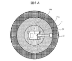
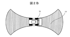
- FIG. 2A and 2B are diagrams showing examples of the movable range of the work machine.
- FIG. 2A shows the movable range 24 of the excavator 1.
- FIG. 2B shows the range of motion 19 of wheel loader 36 .
- a movable range 24A related to the front working section 23 of the hydraulic excavator 1 is a reachable range of the front working section 23 when the upper revolving body rotates 360 degrees when the front working section chief takes the longest posture. becomes.
- the movable range 24B of the undercarriage 14 is a range that the vehicle body can reach, for example, in T seconds when the hydraulic excavator 1 travels.
- a movable range obtained by integrating the movable ranges 24 ⁇ /b>A and 24 ⁇ /b>B is defined as a movable range 24 related to the hydraulic excavator 1 .
- the movable range 19 of the wheel loader 36 is the range in which the wheel loader 36 can move in the front-rear direction for T seconds with the steering wheel turned to the left and right to the limit.
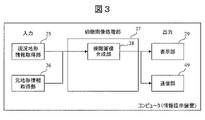
- FIG. 3 is a block diagram showing a functional configuration example of the information presentation device according to this embodiment.
- the information presentation device has a current topography information acquisition unit 25 , an original topography information acquisition unit 26 , a bird's-eye view image processing unit 27 , and a display unit (display device) 29 .
- the bird's-eye view image processing unit 27 has a bird's-eye view image synthesizing unit 28 .
- the information presentation device is composed of, for example, a computer, and a processor included in the computer transfers information from a memory (storage device; hereinafter the same) to each processing unit (current topography information acquisition unit, original topography information acquisition unit, overhead image processing unit, etc.).
- the information presentation device may be arranged in the operator's seat of the working machine 1, or may be arranged in a remote location (for example, a management office) separate from the working machine 1 and the photographing device 33. good.
- the current topography is captured by a camera or other imaging device 33 installed at the construction site 31, and when the image of the current topography is received, the current topography information acquiring unit 25 integrates them into a bird's-eye view image (bird's-eye view image 1). It converts and transmits to the bird's-eye view image synthesizing unit 28 .
- the original topography information acquisition unit 26 is a bird's-eye view image captured by a drone, satellite, or the like (overhead image of the original topography of the construction site 31), or an image drawn based on the design drawing (original topography bird's-eye image: bird's-eye image 2 ).
- the bird's-eye image synthesizing unit 28 superimposes the bird's-eye image 1 created based on the current terrain information on the bird's-eye image 2 of the construction site 31 acquired by the original terrain information acquisition unit 26 to synthesize the image.
- the overhead image synthesizing unit 28 transmits the synthesized overhead image (overhead image 3) to the display unit 29 .
- the display unit 29 displays the bird's-eye view image 3 synthesized by the bird's-eye image synthesis unit 28 on a display device such as a monitor possessed by the operator of the hydraulic excavator (working machine) 1, or by the site worker, the construction manager, and the site supervisor. / Or a display terminal such as a smartphone.
- FIG. 4 is a diagram showing an example of the bird's-eye view image 2 acquired by the original landform information acquisition unit 26.
- a site worker takes an image before construction using a device that can take a bird's-eye view image, such as a drone.
- the image of the original landform can also be drawn based on the design drawing.
- a construction site 31 is divided into an inside construction site 31 , an outside construction site 32 , and a fixed obstacle 30 . It should be noted that the division shall be carried out before the start of construction, and it is not necessary to increase the update frequency.
- the classification method must be set by the site worker or the construction manager, but using a learning function such as deep learning, an algorithm that automatically recognizes the boundaries of the fixed obstacles 30 and the construction site 31 can be used. good too.
- the coordinates of the reference point of the construction site 31 are determined at the time of photographing/drawing the bird's-eye view image.
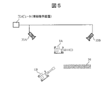
- FIG. 5 is a diagram showing an example of the bird's-eye view image 1 acquired by the current topography information acquisition unit 25.
- At least one photographing device 33 such as a camera is arranged near the construction site 31 or in the construction site 31 at a position and height that can photograph the inside of the construction site 31 . Then, the construction site 31 is photographed by the photographing device 33 .
- the worker manually registers in advance the position (coordinates), height, angle of view, and line-of-sight direction of the imaging device 33, or installs a device capable of self-position estimation such as GNSS and the imaging device 33. is automatically registered in the current topography information acquisition unit 25.
- the current topography information acquisition unit 25 pre-stores (in the above memory) the deformation parameters of the images captured by the image capturing device 33 for each image capturing device 33 .
- the deformation parameter of the image is data that can be specified (determined) based on the installation position and line-of-sight direction of the photographing device 33 .
- the method for generating the bird's-eye view image 1 is not limited to this.
- a three-dimensional image of the construction site 31 is created by performing triangulation on a plurality of images acquired by the current topography information acquisition unit 25, and an overall bird's-eye view image (bird's-eye view image 1) is created based on the three-dimensional image thus obtained. You may create it.
- FIG. 6 is a diagram showing an example of a bird's-eye view image 3 generated by the bird's-eye view image synthesizing unit 28 by superimposing the current landform information (bird's-eye view image 1) on the original landform information (bird's-eye view image 2).
- the bird's-eye view image 1 of the current landform created by the current landform information acquisition unit 25 is compared with the reference point of the original landform information (bird's-eye view image 2) based on the position information of each imaging device 33, and the position to be synthesized is adjusted. generates a bird's-eye view image 3.
- FIG. 7 is a flowchart for explaining the details of the bird's-eye view image generation process for generating the bird's-eye view image 3 according to this embodiment.
- each processing unit (the current topography information acquisition unit 25, the original topography information acquisition unit 26, the bird's-eye view image synthesizing unit 28) is the main body of operation. Since it is implemented by being read by a processor of a computer (information presentation device) from , the processor may be the main body of operation.
- the original topography information acquisition unit 26 acquires a bird's-eye view image captured by a drone, satellite, or the like, or an image (bird's-eye image 2) drawn based on a design drawing, and transmits the bird's-eye image 2 to the bird's-eye image synthesizing unit 28.
- the bird's-eye view image 2 may be, for example, an image stored in advance in a database or storage device, or may be an image captured or obtained by an operator or construction manager and input to an information presentation device.
- step 102 The current landform information acquisition unit 25 receives an image of the current landform captured by at least one imaging device 33 and transmitted therefrom.
- Step 103 The current terrain information acquisition unit 25 aligns the images (images from the plurality of image capturing devices 33) received in step 102 with a predetermined reference point (for example, any pixel or area of any one image). They are integrated together and converted into a bird's-eye view image (bird's-eye view image 1). Then, the current topography information acquisition unit 25 transmits the generated bird's-eye view image 1 to the bird's-eye view image synthesizing unit 28 .
- a predetermined reference point for example, any pixel or area of any one image.
- Step 104 The overhead image synthesizing unit 28 synthesizes or converts the overhead image 2 received from the original topography information acquisition unit 26 and the overhead image 1 received from the current topography information acquisition unit 25 to generate a synthetic overhead image (overhead image 3). , to the display unit 29 .
- Step 105 The display unit 29 displays the overhead image 3 on the display screen.
- the operator, construction manager, operator of the hydraulic excavator (working machine) 1, surrounding workers, and/or site supervisor can grasp the situation of the construction site from a bird's-eye view.
- the operator, construction manager, operator of the hydraulic excavator (working machine) 1, surrounding workers, and/or site supervisor can grasp the situation of the construction site from a bird's-eye view.
- the second embodiment provides information presentation capable of presenting the blind spot 40 to the operator of the hydraulic excavator (working machine) 1 when there is a blind spot (the blind spot 40 described later) at the construction site 31. It is to provide an apparatus and an information presentation method.
- FIGS. 8 to 11 An information presentation device according to a second embodiment of the present disclosure will be described using FIGS. 8 to 11.
- FIG. 8 to 11 the same reference numerals as those in FIGS. 1 to 7 indicate the same parts or processing units, and thus the description thereof will be omitted.
- the bird's-eye image of the current terrain is superimposed on the bird's-eye image of the original terrain. and a judgment unit 38 for judging that the bird's-eye view image information of the current terrain is insufficient according to the calculated distance to the blind spot 40 and area of the blind spot 40 .
- FIG. 8 is a block diagram showing a functional configuration example of an information presentation device according to the second embodiment.
- the blind spot calculation unit 39 divides the bird's-eye view image 1 into grids based on the bird's-eye view image of the current terrain created by the current terrain information acquisition unit 25 (bird's-eye image 1). Calculate the area of the mass outside the shooting range of .
- the range of the blind spot 40 can be estimated in detail from the position, height, line-of-sight direction, and angle of view of the imaging device 33 .
- the determination unit 38 determines whether or not the information of the bird's-eye view image 1 is insufficient according to the result calculated by the blind spot calculation unit 39 . Specifically, when the area of the blind spot 40 at the construction site 31 exceeds a certain threshold for the area of the entire construction site 31, the determination unit 38 outputs information (for safe operation of the work machine 1 (body) necessary information) is determined to be insufficient. By doing so, for example, when the work machine (hydraulic excavator) 1 works near the blind spot, there is a possibility that an obstacle suddenly appearing from the blind spot 40 of the fixed obstacle 30 will come into contact with the front working part 23 or the counterweight 11. Therefore, it is possible to issue a warning in advance, mainly when turning or traveling.
- the threshold for the area of the blind spot 40 can be arbitrarily set by the construction manager. Further, when the position (coordinates) of the work machine 1 can be estimated using GNSS or the like, the imaging device 33, or the like, the distance between the work machine 1 and the blind spot 40 is equal to or less than a threshold, for example, the movable range of the work machine 1. 24 and the area of the corresponding blind spot 40 is a certain amount or more, it is determined that necessary information (information necessary for safely operating the work machine 1 (vehicle body)) is insufficient. good too.
- the display unit 29 displays a bird's-eye view image 4 (with blind spots added) generated by performing display processing such as filling in blind spots 40 in a bird's-eye image (bird's-eye image 3) obtained by synthesizing the bird's-eye images 1 and 2. a bird's-eye view image). This allows the operator, construction manager, surrounding workers, and/or site supervisor to visualize the blind spot 40 of the construction site 31 . Further, when the determination unit 38 determines that the necessary information is insufficient, the display unit 29 displays a warning such as "insufficient information". In addition to a display device such as a monitor and a display terminal such as a smartphone, the display unit 29 may issue a warning by voice.
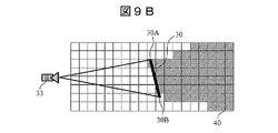
- ⁇ Calculation of blind spot 40> A method of calculating the blind spot 40 (presence or absence of the blind spot, position of the blind spot, width (size) of the blind spot) will be described in detail with reference to FIGS. 9A to 9C.
- the photographing device 33 such as a camera
- the line connecting the ends 30A and 30B of the fixed obstacle 30 and the center point of the photographing device 33 becomes the blind spot line 41.
- the blind spot is 40 on the inside.
- the blind spot 40 is evenly divided into grids or pixel units (the coordinates that make up the blind spot can be specified), so that the area of the blind spot 40 is the area of the number of squares.
- the lattice is determined to be a square forming the blind spot 40 .
- the threshold can be arbitrarily set.
- the photographing device 33 such as a camera
- the line connecting the upper part 30C of the fixed obstacle and the center point of the photographing device 33 becomes the blind spot line 41, and the depth It is possible to reduce the blind spots of the part.
- the blind spot 40 three-dimensionally, it becomes possible to accurately determine whether or not the work machine 1 can be operated safely.
- FIG. 10 is a diagram showing an example of a bird's-eye view image 4 (a bird's-eye view image generated by adding blind spots to the bird's-eye view image 3) according to the second embodiment.
- the display unit 29 displays the bird's-eye view image 4 generated by superimposing the blind spots 40 of the current topography information acquisition unit 25 on the bird's-eye view image 3 on the display screen of the information presentation device.
- the display unit 29 displays “WARNING” on the display screen to warn of the possibility that another obstacle (not shown) will appear from the blind spot 40 .
- FIG. 11 is a flowchart for explaining the details of the process of generating the bird's-eye view image 4 according to the second embodiment.
- each processing unit (the current terrain information acquisition unit 25, the original terrain information acquisition unit 26, the blind spot calculation unit 39, the bird's-eye view image synthesis unit 28, and the determination unit 38) is the main body of operation.
- the processor of the computer information presentation device
- the processor may be the main body of operation.
- Step 201 The original topography information acquisition unit 26 acquires a bird's-eye view image captured by a drone, satellite, or the like, or an image (bird's-eye image 2) drawn based on a design drawing, and transmits the bird's-eye image 2 to the bird's-eye image synthesizing unit 28.
- the bird's-eye view image 2 may be, for example, an image stored in advance in a database or a storage device, or an image captured or obtained by an operator or a construction manager and input to an information presentation device. good too.
- step 202 The current landform information acquisition unit 25 receives an image of the current landform captured by at least one imaging device 33 and transmitted therefrom.
- Step 203 The current terrain information acquisition unit 25 aligns the images (images from the plurality of image capturing devices 33) received in step 202 with predetermined reference points (for example, arbitrary pixels or areas of any one image). They are integrated together and converted into a bird's-eye view image (bird's-eye view image 1). Then, the current topography information acquisition unit 25 transmits the generated bird's-eye view image 1 to the blind spot calculation unit 39 .
- predetermined reference points for example, arbitrary pixels or areas of any one image.
- Blind spot calculation unit 39 determines the presence or absence of blind spot 40 (see FIGS. 9A to 9C), the area of blind spot 40 (see FIGS. 9A to 9C), and the distance to blind spot 40 (distance: for example, of work machines 1A and 1B). The shortest distance from the movable range 24A or the movable range 24 to the blind spot 40) is calculated. The blind spot calculation unit 39 then transmits information (presence, presence, area, and distance) of the blind spots 40 together with the bird's-eye view image 1 to the bird's-eye view image synthesizing unit 28 .
- Step 205 The bird's-eye view image synthesizing unit 28 synthesizes or converts the bird's-eye view image 2 received from the original landform information acquisition unit 26 and the bird's-eye view image 1 received from the blind spot calculation unit 39 (which may be received directly from the current landform information acquisition unit 25). Then, a synthetic bird's-eye view image (bird's-eye view image 3) is generated, and the bird's-eye view image 4 (bird's-eye view image including the blind spot) is generated by synthesizing the bird's-eye view image 3 with the blind spot 40 received from the blind spot calculation unit 39 .
- a synthetic bird's-eye view image (bird's-eye view image 3) is generated
- the bird's-eye view image 4 birds's-eye view image including the blind spot) is generated by synthesizing the bird's-eye view image 3 with the blind spot 40 received from the blind spot calculation unit 39 .
- the bird's-eye view image synthesizing unit 28 transmits information on the bird's-eye view image 4 and the blind spot 40 (for example, at least the area of the blind spot among the presence or absence of the blind spot, the area, and the distance) to the determination unit 38 .
- step 206 Based on the information received from the bird's-eye view image synthesizing unit 28, the determination unit 38 determines whether necessary information (information necessary for safely operating the work machine 1 (body)) has been acquired. For example, the distance from work machine 1 to blind spot 40 (shortest distance from movable range 24A of working machines 1A and 1B or movable range 24 to blind spot 40) is greater than a predetermined threshold (distance threshold), and the area of blind spot 40 is If it is equal to or less than the predetermined threshold, it is determined that the necessary information has been acquired. If it is determined that the necessary information has been acquired (Yes in step 206), the process proceeds to step 207. If it is determined that the necessary information has not been obtained (No in step 206), the process proceeds to step 208.
- a predetermined threshold distance threshold
- step 207 The display unit 29 displays the overhead image 4 on the display screen.
- the construction manager, the operator of the hydraulic excavator (work machine) 1, the surrounding workers, and/or the site supervisor can grasp the situation of the construction site from a bird's-eye view, and the work machine 1 at the construction site 31 can be It is possible to operate safely.
- Step 208 The display unit 29 superimposes a "warning” (such as a word “warning” or a mark for notifying danger) on the bird's-eye view image 4 and displays it on the display screen.
- a "warning” such as a word “warning” or a mark for notifying danger
- the construction manager, the operator of the hydraulic excavator (work machine) 1, surrounding workers, and/or the site supervisor can grasp the situation of the construction site from a bird's-eye view. It is possible to grasp the danger of maneuvering.
- FIG. 12 to 15 the same reference numerals as those in FIGS. 1 to 11 denote the same parts or processing units, and thus the description thereof will be omitted.
- the photographing device 33 is arranged around the construction site 31, and it is determined whether or not necessary information is lacking from the area of the blind spot 40 in the acquired current terrain, and the operator and surrounding workers and warned the foreman.
- data of an in-vehicle bird's-eye view image 48 created based on an image captured by an in-vehicle imaging device 33 is synthesized (overlaid) with the current topography information (bird's-eye view image 1) so that the blind spot 40 can be detected. It has the function of reducing the area.
- FIG. 12 is a block diagram showing a functional configuration example of an information presentation device according to the third embodiment.
- the information presentation device includes, in addition to the components shown in FIG. , is equipped with
- the vehicle body azimuth angle calculation unit 43 acquires the azimuth of the work machine 1 on the construction site basis based on the position information from the vehicle body position detection unit 44, and transmits the information on the azimuth to the in-vehicle bird's-eye view image correction unit 46. Further, the vehicle body position detection unit 44 identifies the position of the work machine 1 based on the construction site basis or the global coordinate basis, and transmits information on the position to the in-vehicle bird's-eye view image correction unit 46 .
- the in-vehicle bird's-eye image creating unit 45 transmits a bird's-eye image created based on the vehicle-mounted imaging device 33 (hereinafter referred to as an in-vehicle bird's-eye image 48 ) to the in-vehicle bird's-eye image correction unit 46 .
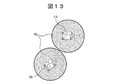
- FIG. 13 is a diagram showing an example of the in-vehicle bird's-eye view image 48.
- the vehicle-mounted bird's-eye view image 48 is synthesized with the bird's-eye view image of the current landform at different positions and directions depending on the position and orientation of the work machine 20 . Therefore, first, from the positional relationship between the position information of the work machines 1A and 1B and the reference point of the construction site 31, the position where the in-vehicle bird's-eye view image 48 is synthesized is specified.
- the vehicle-mounted bird's-eye view image correction unit 46 rotates the image data by the azimuth angle of the work machines. Furthermore, by projecting the rotated image data onto a bird's-eye view image according to the positions of the acquired work machines 1A and 1B and synthesizing them, it is possible to display the vehicle-mounted bird's-eye view image 48 on the bird's-eye view image of the construction site.
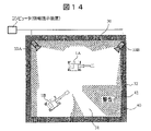
- FIG. 14 is a diagram showing an example of a synthesized bird's-eye view image 5 according to the third embodiment.
- the bird's-eye view image 5 shown in FIG. 14 is an image obtained by reflecting the vehicle-mounted bird's-eye image 48 on the bird's-eye image 1 and synthesizing it with the bird's-eye view image 2: the vehicle-mounted bird's-eye image 48 covers the blind spot 40 of the bird's-eye image 4 shown in FIG. It is an image with the area removed.
- the bird's-eye view image synthesizing unit 28 further superimposes the bird's-eye view image 2 from the original topography information acquisition unit 26 on the bird's-eye view image (the image obtained by superimposing the blind spot 40 and the in-vehicle bird's-eye image 48 on the bird's-eye image 1) from the blind spot calculation unit 39. By doing so, the bird's-eye view image 5 can be generated.
- the display switching unit 47 can switch between the in-vehicle bird's-eye view image 48 and the bird's-eye view image 5 (surroundings bird's-eye view image) using a button or the touch screen of the monitor.
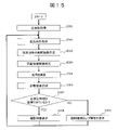
- FIG. 15 is a flowchart for explaining the details of the process of generating the bird's-eye view image 5 according to the third embodiment.
- each processing unit current topography information acquisition unit 25, original topography information acquisition unit 26, blind spot calculation unit 39, overhead image synthesis unit 28, determination unit 38, vehicle azimuth angle calculation unit, vehicle position detection unit 44, in-vehicle bird's-eye view image creation unit 45, and display switching unit 47
- the processor may be the main body of operation.
- Step 301 The original topography information acquisition unit 26 acquires a bird's-eye view image captured by a drone, satellite, or the like, or an image (bird's-eye image 2) drawn based on a design drawing, and transmits the bird's-eye image 2 to the bird's-eye image synthesizing unit 28.
- the bird's-eye view image 2 may be, for example, an image stored in advance in a database or a storage device, or an image captured or obtained by an operator or a construction manager and input to an information presentation device. good too.
- step 302 The current landform information acquisition unit 25 receives an image of the current landform captured by at least one imaging device 33 and transmitted therefrom.
- Step 303 The current topography information acquisition unit 25 aligns the images received in step 302 (images from the plurality of photographing devices 33) to a predetermined reference point (for example, any pixel or area of any one image). They are integrated together and converted into a bird's-eye view image (bird's-eye view image 1). Then, the current topography information acquisition unit 25 transmits the generated bird's-eye view image 1 to the blind spot calculation unit 39 .
- a predetermined reference point for example, any pixel or area of any one image.
- Step 304 The in-vehicle bird's-eye view image correction unit 46 receives the in-vehicle bird's-eye view image of the work machine 1 from the in-vehicle bird's-eye image creation unit 45 , the information on the azimuth angle of the work machine 1 from the vehicle body azimuth angle calculation unit 43 , and the work machine 1 from the vehicle body position detection unit 44 . Get the position information of each. Then, the vehicle-mounted bird's-eye image correction unit 46 corrects the vehicle-mounted bird's-eye image of the work machine 1 based on the information on the azimuth angle and position of the work machine 1, and transmits the corrected vehicle-mounted bird's-eye image to the bird's-eye image synthesizing unit 28. .
- the blind spot calculator 39 determines the presence or absence of the blind spot 40 (see FIGS. 9A to 9C), the area of the blind spot 40 (see FIGS. 9A to 9C), and the distance to the blind spot 40 (distance: for example, working machines 1A and 1B). or the shortest distance from the movable range 24 to the blind spot 40).
- the blind spot calculation unit 39 then transmits information (presence, presence, area, and distance) of the blind spots 40 together with the bird's-eye view image 1 to the bird's-eye view image synthesizing unit 28 .
- step 306 The bird's-eye view image synthesizing unit 28 receives the bird's-eye view image 2 received from the original topography information acquisition unit 26, the bird's-eye view image 1 and information on the blind spot 40 received from the blind spot calculation unit 39, and the vehicle-mounted bird's-eye image received from the vehicle-mounted bird's-eye image correction unit 46. Based on (corrected in-vehicle overhead image) 48 (combining these), overhead image 5 (see FIG. 14) reflecting blind spot 40 and in-vehicle overhead image is generated. Then, the bird's-eye view image synthesizing unit 28 transmits the bird's-eye view image 5 to the determination unit 38 .
- step 307 Based on the information received from the bird's-eye view image synthesizing unit 28, the determination unit 38 determines whether necessary information (information necessary for safely operating the work machine 1 (body)) has been acquired. For example, the distance from work machine 1 to blind spot 40 (shortest distance from movable range 24A of working machines 1A and 1B or movable range 24 to blind spot 40) is greater than a predetermined threshold (distance threshold), and the area of blind spot 40 is If it is equal to or less than the predetermined threshold, it is determined that the necessary information has been obtained. If it is determined that the necessary information has been acquired (Yes in step 307), the process proceeds to step 308. If it is determined that the necessary information has not been obtained (No in step 307), the process proceeds to step 309.
- necessary information information necessary for safely operating the work machine 1 (body)
- Step 308 The display unit 29 displays the overhead image 5 on the display screen.
- the construction manager, the operator of the hydraulic excavator (work machine) 1, the surrounding workers, and/or the site supervisor can grasp the situation of the construction site from a bird's-eye view, and the work machine 1 at the construction site 31 can be It is possible to operate safely.
- Step 309 The display unit 29 superimposes a "warning” (such as a word “warning” or a mark for notifying danger) on the bird's-eye view image 5 and displays it on the display screen.
- a "warning” such as a word “warning” or a mark for notifying danger
- the construction manager, the operator of the hydraulic excavator (work machine) 1, surrounding workers, and/or the site supervisor can grasp the situation of the construction site from a bird's-eye view. It is possible to grasp the danger of maneuvering.
- the information presentation device includes a first bird's-eye view image (bird's-eye view image 1) that provides a bird's-eye view of the current topography of the construction site 31, and A first synthetic bird's-eye view image obtained by superimposing a second bird's-eye view image (bird's-eye view image 2) that represents a bird's-eye view of the original topography of the construction site acquired by a method other than photography by the device 33 (for example, photography by a drone or satellite).
- bird's-eye view image 3 is generated and output (displayed on the display screen of the display unit 29).
- the bird's-eye view image 2 that originally exists in the current situation image acquired by the photographing device is used complementarily to generate the bird's-eye view image of the entire current construction site.
- a worker can be provided with a useful bird's-eye view image of a construction site.
- the information presentation device uses the first bird's-eye view image (bird's-eye view image 1) acquired by the imaging device 33 to identify the blind spot 40 at the construction site, and the image of the blind spot 40 is reflected in the first synthetic bird's-eye image (bird's-eye image 3) to generate and output a second synthetic bird's-eye image (bird's-eye image 4).
- the possibility that another work machine or the like may come out of the blind spot 40 can be grasped from a bird's-eye view, so that the work machine can be operated safely.
- the information presentation device converts the vehicle-mounted bird's-eye image generated based on the image captured by the vehicle-mounted camera installed on the work machine 1 into the second synthesized bird's-eye image (bird's-eye image 4). ) to generate and output a third synthesized bird's-eye view image (bird's-eye view image 5).
- the area of the blind spot 40 can be reduced, and the work machine can be operated more safely.
- the functionality of the embodiments of the present disclosure can also be implemented by software program code.
- a storage medium recording the program code is provided to the system or device, and the computer (or CPU or MPU) of the system or device reads the program code stored in the storage medium.
- the program code itself read from the storage medium implements the functions of the above-described embodiments, and the program code itself and the storage medium storing it constitute the present disclosure.
- Storage media for supplying such program code include, for example, flexible disks, CD-ROMs, DVD-ROMs, hard disks, optical disks, magneto-optical disks, CD-Rs, magnetic tapes, non-volatile memory cards, and ROMs. etc. are used.
- the OS operating system
- the processing implements the functions of the above-described embodiments.
- the CPU of the computer performs part or all of the actual processing based on the instructions of the program code. may implement the functions of the above-described embodiment.
- the program code of the software that realizes the functions of the embodiment can be transferred to storage means such as the hard disk and memory of the system or device, or storage media such as CD-RW and CD-R.
- storage means such as the hard disk and memory of the system or device, or storage media such as CD-RW and CD-R.
- the computer (or CPU or MPU) of the system or device may read and execute the program code stored in the storage means or the storage medium at the time of use.
- control lines and information lines indicate those that are considered necessary for explanation, and not all the control lines and information lines are necessarily indicated on the product. All configurations may be interconnected.
Landscapes
- Engineering & Computer Science (AREA)
- Physics & Mathematics (AREA)
- General Physics & Mathematics (AREA)
- Theoretical Computer Science (AREA)
- General Engineering & Computer Science (AREA)
- Civil Engineering (AREA)
- Mining & Mineral Resources (AREA)
- Structural Engineering (AREA)
- Multimedia (AREA)
- Component Parts Of Construction Machinery (AREA)
- Image Processing (AREA)
- Computer Vision & Pattern Recognition (AREA)
- Closed-Circuit Television Systems (AREA)
- Geometry (AREA)
- Signal Processing (AREA)
Abstract
Description
<俯瞰画像提供システムの構成例>
図16は、本実施形態(後述の第2および第3の実施形態を含む)による俯瞰画像提供システム(情報提供システムとも言う)の構成例を示す図である。
俯瞰画像提供システムは、通信装置を有する作業機械1と、施工現場31に設置された少なくとも1つの撮影装置(カメラ)33Aから33Bと、施工現場31の各種俯瞰画像を生成し、出力するコンピュータ(情報提示装置)と、施工現場31の元々の地形(建設資材や作業機械1を配置する前の地形)の俯瞰画像を撮影するためのドローン(元地形情報取得部26に相当)と、生成された俯瞰画像を表示する表示部(表示装置)29と、通信装置49と、を備えている。
図1は、作業機械の概略構成例を示す図である。本実施形態では、作業機械の一例として油圧ショベル1を挙げて説明する。
油圧ショベル1は、下部走行体14に旋回機構16を介して上部走行体15が搭載されて構成される。旋回機構16は、油圧モータを含み、上部走行体15を時計回りまたは反時計回りに旋回動作を行う。上部走行体15にはブーム8が取り付けられている。ブーム8は、油圧駆動されるブームシリンダ5により、上部走行体15に対して上下方向に揺動する。ブーム8の先端にはアーム9が取り付けられている。アーム9は、油圧駆動されるアームシリンダ6により、ブーム8に対して前後方向に揺動する。アーム9の先端にはバケット10が取り付けられている。バケット10は、油圧駆動されるバケットシリンダ7により、アーム9に対して揺動する。上部走行体15には、さらにオペレータを収容するキャブ2が搭載されている。なお、本明細書において、ブーム8、アーム9、及びバケット10をまとめてフロント作業部23と称する場合がある。フロント作業部23は、上部旋回体15と共に、旋回中心17を中心として旋回する。また、旋回中心17からフロント作業部23の先端までの距離は、ブーム8、アーム9、バケット10を揺動させることにより変動する。ここで、上部走行体15は、旋回中心17を中心として旋回し、上部走行体15にアタッチメント18が取り付けられている。
図2Aおよび図2Bは、作業機械の可動範囲の例を示す図である。図2Aは、油圧ショベル1の可動範囲24を示す。図2Bは、ホイールローダ36の可動範囲19を示す。
図3は、本実施形態による情報提示装置の機能構成例を示すブロック図である。
情報提示装置は、現況地形情報取得部25と、元地形情報取得部26と、俯瞰画像処理部27と、表示部(表示装置)29を有している。俯瞰画像処理部27は、俯瞰画像合成部28と、を有している。当該情報提示装置は、例えば、コンピュータで構成され、コンピュータに含まれるプロセッサが、メモリ(記憶デバイス;以下同様)から各処理部(現況地形情報取得部、元地形情報取得部、俯瞰画像処理部など)を実現するプログラムを読み込み、内部メモリ上に展開することにより、上記各処理部を実現する。また、情報提示装置は、作業機械1の操縦席に配置するようにしてもよいし、作業機械1や撮影装置33とは別の遠隔地(例えば、管理事務所)に配置するようにしてもよい。
図4は、元地形情報取得部26にて取得した俯瞰画像2の一例を示す図である。現場作業員がドローン等の俯瞰画像を撮影することが可能な機器を用いて、施工前の画像を撮影する。なお、元地形の画像は設計図を基に描写することも可能である。元地形の画像においては、施工現場31が施工現場31内と施工現場外32そして固定障害物30に区分けされている。なお、区分けは、施工開始前に実施することとし、必ずしも更新頻度を高くする必要はない。区分け方法は、現場作業員もしくは施工管理者が主導で設定する必要があるが、ディープラーニング等の学習機能を用いて、固定障害物30や施工現場31の境界を自動で認識するアルゴリズムを用いてもよい。また、俯瞰画像の撮影/描写時は、施工現場31の基準点の座標を決定しておく。
図5は、現況地形情報取得部25にて取得した俯瞰画像1の一例を示す図である。施工現場31付近あるいは施工現場31内に、施工現場31内を撮影できる位置および高さにカメラなどの撮影装置33を少なくとも1つ配置する。そして、撮影装置33によって、施工現場31を撮影する。作業員はあらかじめ、撮影装置33を配置した位置(座標)、高さ、撮影装置33の画角および視線方向を手動で登録、もしくは、GNSS等の自己位置推定が可能な機器と撮影装置33とを紐づけたデータを自動で現況地形情報取得部25に登録する。
図6は、俯瞰画像合成部28が現況地形情報(俯瞰画像1)を元地形情報(俯瞰画像2)に重ねることにより生成する俯瞰画像3の一例を示す図である。
現況地形情報取得部25にて作成した現況地形の俯瞰画像1をそれぞれの撮影装置33の位置情報を基に元地形情報(俯瞰画像2)の基準点と照らし合わせ、合成する位置を調整することにより、俯瞰画像3を生成する。
図7は、本実施形態による俯瞰画像3を生成する俯瞰画像生成処理の詳細を説明するためのフローチャートである。以下説明する各ステップでは、各処理部(現況地形情報取得部25、元地形情報取得部26、俯瞰画像合成部28)を動作主体とするが、上述のように、これらに相当するプログラムがメモリからコンピュータ(情報提示装置)のプロセッサによって読み込まれて実現されるため、プロセッサを動作主体としてもよい。
元地形情報取得部26は、ドローンや衛星などより撮影した俯瞰画像、もしくは設計図を基に描写した画像(俯瞰画像2)を取得し、当該俯瞰画像2を俯瞰画像合成部28に送信する。なお、この俯瞰画像2は、例えば、あらかじめデータベースや記憶装置に格納されている画像であってもよいし、オペレータや施工管理者などが改めて撮像あるいは入手し、情報提示装置に入力した画像であってもよい。
現況地形情報取得部25は、少なくとも1つの撮影装置33が撮像し、そこから送信されてきた現況地形の画像を受信する。
現況地形情報取得部25は、ステップ102で受信した画像(複数の撮影装置33からの画像)を、予め決められた所定の基準点(例えば、いずれか1つの画像の任意の画素あるいは領域)に合わせて統合して俯瞰画像(俯瞰画像1)に変換する。そして、現況地形情報取得部25は、生成した俯瞰画像1を俯瞰画像合成部28に送信する。
俯瞰画像合成部28は、元地形情報取得部26から受信した俯瞰画像2と現況地形情報取得部25から受信した俯瞰画像1とを合成または変換し、合成俯瞰画像(俯瞰画像3)を生成し、これを表示部29に送信する。
表示部29は、俯瞰画像3を表示画面上に表示する。これにより、オペレータや施工管理者、油圧ショベル(作業機械)1の作業者、周囲作業員、および/または現場監督は、施工現場の状況を俯瞰的に把握することができる。
このように、元地形の俯瞰画像に現況地形の俯瞰画像を重ねることで、現況地形の俯瞰画像の情報が不足している場合、俯瞰画像を補完することが可能となる。
施工現場31で使用可能な撮影装置33の個数が限られている場合、作業現場内において死角40ができる可能性が高い。この場合、油圧ショベル(作業機械)1のオペレータに死角40の存在を提示しないと、障害物(別の作業機械等)が固定障害物30の死角40から出てくる可能性を考慮した動作(作業)を行うことが困難な場合がある。
図8は、第2の実施形態による情報提示装置の機能構成例を示すブロック図である。当該情報提示装置において、死角演算部39は、現況地形情報取得部25が作成した現況地形の俯瞰画像(俯瞰画像1)を基に、例えば、当該俯瞰画像1を格子状に区切り、撮影装置33の撮影範囲外のマスの面積を演算する。もしくは、撮影装置33の位置、高さ、視線方向および画角から死角40の範囲を詳細に推定することも可能である。
図9Aから図9Cを用いて死角40(死角の有無、死角の位置、死角の広さ(大きさ))の演算方法について詳しく説明する。まず、カメラ等の撮影装置33にて固定障害物30を撮影した場合、固定障害物30の端部30Aおよび30Bと撮影装置33の中心点を結んだ線が死角線41となり、死角線41の内側が死角40となる。続いて、図9Bに示すように死角40を均等に格子状またはピクセル単位ごとに区切る(これにより死角を構成する座標が特定することができる)ことで死角40の面積を四角形の個数分の面積で表すことができる。そのため、より厳密に死角40の面積を判定したい場合は、より細かに格子状に区切る必要がある。なお、四角形(格子)ごとに死角線41の内側(死角として隠れた部分)の面積が閾値以上となった場合に、その格子が死角40をなす四角形であると判定する。なお、当該閾値は任意に設定することが可能である。
以上のように、3次元的に死角40を特定することにより、作業機械1が安全に動作させることができるか否かを正確に判定することができるようになる。
図10は、第2の実施形態による俯瞰画像4(俯瞰画像3に死角を加味して生成した俯瞰画像)の例を示す図である。
図10に示すように、表示部29は、俯瞰画像3に現況地形情報取得部25の死角40を重ね合わせて生成された俯瞰画像4を情報提示装置の表示画面に表示する。さらに、表示部29は、死角40の面積が大きい場合、表示画面に「警告」と表示し、死角40から別の障害物(図示せず)が出てくる可能性を警告する。
図11は、第2の実施形態による俯瞰画像4を生成する処理の詳細を説明するためのフローチャートである。以下説明する各ステップでは、各処理部(現況地形情報取得部25、元地形情報取得部26、死角演算部39、俯瞰画像合成部28、判定部38)を動作主体とするが、上述のように、これらに相当するプログラムがメモリからコンピュータ(情報提示装置)のプロセッサによって読み込まれて実現されるため、プロセッサを動作主体としてもよい。
元地形情報取得部26は、ドローンや衛星などより撮影した俯瞰画像、もしくは設計図を基に描写した画像(俯瞰画像2)を取得し、当該俯瞰画像2を俯瞰画像合成部28に送信する。なお、この俯瞰画像2は、例えば、あらかじめデータベースや記憶装置に格納されている画像であってもよいし、オペレータや施工管理者が改めて撮像あるいは入手し、情報提示装置に入力した画像であってもよい。
現況地形情報取得部25は、少なくとも1つの撮影装置33が撮像し、そこから送信されてきた現況地形の画像を受信する。
現況地形情報取得部25は、ステップ202で受信した画像(複数の撮影装置33からの画像)を、予め決められた所定の基準点(例えば、いずれか1つの画像の任意の画素あるいは領域)に合わせて統合して俯瞰画像(俯瞰画像1)に変換する。そして、現況地形情報取得部25は、生成した俯瞰画像1を死角演算部39に送信する。
死角演算部39は、死角40の有無(図9Aから図9Cを参照)、死角40の面積(図9AからCを参照)、および死角40までの距離(距離:例えば、作業機械1Aおよび1Bの可動範囲24Aあるいは可動範囲24から死角40までの最短距離)を演算する。そして、死角演算部39は、俯瞰画像1とともに死角40の情報(有無、面積、および距離)を俯瞰画像合成部28に送信する。
俯瞰画像合成部28は、元地形情報取得部26から受信した俯瞰画像2と死角演算部39から受信した俯瞰画像1(現況地形情報取得部25から直接受信してもよい)とを合成または変換して合成俯瞰画像(俯瞰画像3)を生成し、さらに俯瞰画像3に死角演算部39から受信した死角40を合成して俯瞰画像4(死角を加味した俯瞰画像)を生成する。そして、俯瞰画像合成部28は、俯瞰画像4および死角40の情報(例えば、死角の有無、面積、および距離のうち、少なくとも死角の面積)を判定部38に送信する。
判定部38は、俯瞰画像合成部28から受信した情報に基づいて、必要な情報(作業機械1(車体)を安全に動作させるために必要な情報)が取得できているか否か判断する。例えば、作業機械1から死角40までの距離(作業機械1Aおよび1Bの可動範囲24Aあるいは可動範囲24から死角40までの最短距離)が所定の閾値(距離閾値)より大きい、かつ死角40の面積が所定閾値以下である場合に、必要な情報が取得できていると判定される。必要な情報が取得できていると判定された場合(ステップ206でYesの場合)、処理はステップ207に移行する。必要な情報が取得できていないと判定された場合(ステップ206でNoの場合)、処理はステップ208に移行する。
表示部29は、俯瞰画像4を表示画面上に表示する。これにより、施工管理者、油圧ショベル(作業機械)1のオペレータ、周囲作業員、および/または現場監督は、施工現場の状況を俯瞰的に把握することができ、施工現場31において作業機械1を安全に操縦することが可能となる。
表示部29は、俯瞰画像4に「警告」(警告という文字や危険を知らせるためのマークなど)を重畳して表示画面上に表示する。これにより、施工管理者、油圧ショベル(作業機械)1のオペレータ、周囲作業員、および/または現場監督は、施工現場の状況を俯瞰的に把握することができ、施工現場31における作業機械1の操縦の危険性を把握することが可能となる。
図12から図15を用いて、本開示の第3の実施形態による情報提示装置について説明する。なお、図12から図15において、図1から図11と同一の符号は同一の部品あるいは処理部を示すため、再度の説明は省略する。
図12は、第3の実施形態に係る情報提示装置の機能構成例を示すブロック図である。図12に示すように、当該情報提示装置は、図8の構成要素に加えて、車体方位角度演算部43と、車体位置検出部44と、車載俯瞰画像作成部45と、表示切換え部47と、を備えている。
図13は、車載俯瞰画像48の例を示す図である。ここで、車載俯瞰画像48は作業機械20の位置と方位に応じて現況地形の俯瞰画像と合成する位置と方向が異なる。そこで、まず作業機械1Aおよび1Bの位置情報と施工現場31の基準点の位置関係から車載俯瞰画像48を合成する位置を特定する。
図14は、第3の実施形態による、合成した俯瞰画像5の例を示す図である。なお、図14に示す俯瞰画像5は、俯瞰画像1に車載俯瞰画像48を反映させ、それに俯瞰画像2を合成した画像:図10に示す俯瞰画像4の死角40から車載俯瞰画像48がカバーする領域を取り除いた画像となっている。
表示切換え部47は、車載俯瞰画像48と俯瞰画像5(周囲俯瞰画像)をボタン式またはモニタのタッチスクリーンなどで切り換えることが可能である。
図15は、第3の実施形態による俯瞰画像5を生成する処理の詳細を説明するためのフローチャートである。以下説明する各ステップでは、各処理部(現況地形情報取得部25、元地形情報取得部26、死角演算部39、俯瞰画像合成部28、判定部38、車体方位角度演算部、車体位置検出部44、車載俯瞰画像作成部45、表示切換え部47)を動作主体とするが、上述のように、これらに相当するプログラムがメモリからコンピュータ(情報提示装置)のプロセッサによって読み込まれて実現されるため、プロセッサを動作主体としてもよい。
元地形情報取得部26は、ドローンや衛星などより撮影した俯瞰画像、もしくは設計図を基に描写した画像(俯瞰画像2)を取得し、当該俯瞰画像2を俯瞰画像合成部28に送信する。なお、この俯瞰画像2は、例えば、あらかじめデータベースや記憶装置に格納されている画像であってもよいし、オペレータや施工管理者が改めて撮像あるいは入手し、情報提示装置に入力した画像であってもよい。
現況地形情報取得部25は、少なくとも1つの撮影装置33が撮像し、そこから送信されてきた現況地形の画像を受信する。
現況地形情報取得部25は、ステップ302で受信した画像(複数の撮影装置33からの画像)を、予め決められた所定の基準点(例えば、いずれか1つの画像の任意の画素あるいは領域)に合わせて統合して俯瞰画像(俯瞰画像1)に変換する。そして、現況地形情報取得部25は、生成した俯瞰画像1を死角演算部39に送信する。
車載俯瞰画像補正部46は、車載俯瞰画像作成部45から作業機械1の車載俯瞰画像を、車体方位角度演算部43から作業機械1の方位角度の情報を、車体位置検出部44から作業機械1の位置の情報をそれぞれ取得する。そして、車載俯瞰画像補正部46は、作業機械1の方位角度および位置の情報に基づいて、作業機械1の車載俯瞰画像を補正し、補正された車載俯瞰画像を俯瞰画像合成部28に送信する。
死角演算部39は、死角40の有無(図9Aから図9Cを参照)、死角40の面積(図9Aから図9Cを参照)、および死角40までの距離(距離:例えば、作業機械1Aおよび1Bの可動範囲24Aあるいは可動範囲24から死角40までの最短距離)を演算する。そして、死角演算部39は、俯瞰画像1とともに死角40の情報(有無、面積、および距離)を俯瞰画像合成部28に送信する。
俯瞰画像合成部28は、元地形情報取得部26から受信した俯瞰画像2と、死角演算部39から受信した俯瞰画像1および死角40の情報と、車載俯瞰画像補正部46から受信した車載俯瞰画像(補正された車載俯瞰画像)48とに基づいて(これらを合成して)、死角40および車載俯瞰画像を反映した俯瞰画像5(図14参照)を生成する。そして、俯瞰画像合成部28は、俯瞰画像5を判定部38に送信する。
判定部38は、俯瞰画像合成部28から受信した情報に基づいて、必要な情報(作業機械1(車体)を安全に動作させるために必要な情報)が取得できているか否か判断する。例えば、作業機械1から死角40までの距離(作業機械1Aおよび1Bの可動範囲24Aあるいは可動範囲24から死角40までの最短距離)が所定の閾値(距離閾値)より大きい、かつ死角40の面積が所定閾値以下である場合に、必要な情報が取得できていると判定される。必要な情報が取得できていると判定された場合(ステップ307でYesの場合)、処理はステップ308に移行する。必要な情報が取得できていないと判定された場合(ステップ307でNoの場合)、処理はステップ309に移行する。
表示部29は、俯瞰画像5を表示画面上に表示する。これにより、施工管理者、油圧ショベル(作業機械)1のオペレータ、周囲作業員、および/または現場監督は、施工現場の状況を俯瞰的に把握することができ、施工現場31において作業機械1を安全に操縦することが可能となる。
表示部29は、俯瞰画像5に「警告」(警告という文字や危険を知らせるためのマークなど)を重畳して表示画面上に表示する。これにより、施工管理者、油圧ショベル(作業機械)1のオペレータ、周囲作業員、および/または現場監督などは、施工現場の状況を俯瞰的に把握することができ、施工現場31における作業機械1の操縦の危険性を把握することが可能となる。
(i)第1の実施形態によれば、情報提示装置は、施工現場31の現況地形を俯瞰的に表す第1俯瞰画像(俯瞰画像1)と、施工現場に設置された撮影装置33による撮影以外の方法(例えば、ドローンや衛星による撮影)によって取得された施工現場の元々の地形を俯瞰的に表す第2俯瞰画像(俯瞰画像2)とを重ね合わせて第1合成俯瞰画像(俯瞰画像3)を生成し、出力(表示部29の表示画面上に表示)する。このように、撮影装置で取得した現況画像に元々存在する俯瞰画像2を補完的に用いて現在の施工現場全体の俯瞰画像を生成するので、施工現場における撮影装置33の設置台数が少なくても有益な施工現場の俯瞰画像を作業者に提供することができる。
25 現況地形情報取得部
26 元地形情報取得部
27 俯瞰画像処理部
28 俯瞰画像合成部
29 表示部(表示装置)
30 固定障害物
31 施工現場
32 施工現場外
33 撮影装置
38 判定部
39 死角演算部
43 車体方位角度演算部
44 車体位置検出部
45 車載俯瞰画像作成部
46 車載俯瞰画像補正部
47 表示切換え部
49 通信部(通信装置)
Claims (8)
- 施工現場に関する地形画像を生成して出力する情報提示装置であって、
前記地形画像に所定の画像処理を実行するためのプログラムを格納する記憶デバイスと、
前記記憶デバイスから前記プログラムを読み込み、前記地形画像を生成するプロセッサと、を備え、
前記プロセッサは、
前記施工現場に設置された少なくとも1つの撮影装置によって取得された前記施工現場の画像を用いて、前記施工現場の現況地形を俯瞰的に表す第1俯瞰画像を取得する処理と、
前記施工現場に設置された前記撮影装置による撮影以外の方法によって取得された前記施工現場の元々の地形を俯瞰的に表す第2俯瞰画像を取得する処理と、
前記第1俯瞰画像と前記第2俯瞰画像とを重ね合わせて第1合成俯瞰画像を生成する画像合成処理と、
を実行する、情報提示装置。 - 請求項1において、
前記プロセッサは、さらに、前記第1俯瞰画像に基づいて、前記施工現場における死角を特定するための情報を演算する処理を実行し、
前記画像合成処理において、前記プロセッサは、さらに、前記死角を特定するための情報から前記死角の画像を生成し、前記第1合成俯瞰画像に前記死角の画像を反映した第2合成俯瞰画像を生成する、情報提示装置。 - 請求項2において、
前記プロセッサは、前記第1俯瞰画像を用いて、前記死角を特定するための情報として、前記死角の有無、前記死角の位置、および前記死角の面積を演算する、情報提示装置。 - 請求項3において、
前記プロセッサは、さらに、前記死角を特定するための情報に基づいて、前記施工現場で作業機械を動作させるために必要な情報が取得できているかを判定する処理を実行する、情報提示装置。 - 請求項4において、
前記プロセッサは、前記作業機械から前記死角までの距離が第1閾値より大きく、かつ前記死角の面積が第2閾値未満であるとき、前記施工現場で前記作業機械を動作させるために必要な情報が取得できていると判定する、情報提示装置。 - 請求項5において、
前記プロセッサは、前記作業機械を動作させるために必要な情報が取得できていないと判定したとき、警告を出力する処理を実行する、情報提示装置。 - 請求項2において、
前記プロセッサは、さらに、前記施工現場で動作する作業機械に設置された車載撮影装置が撮影した画像を前記第2合成俯瞰画像に反映させた第3合成俯瞰画像を生成する処理を実行する、情報提示装置。 - 請求項7において、
前記プロセッサは、さらに、表示切換え指示に応答して、前記第3合成俯瞰画像と前記車載撮影装置が撮影した画像とを切り換えて出力する、情報提示装置。
Priority Applications (5)
| Application Number | Priority Date | Filing Date | Title |
|---|---|---|---|
| EP22774540.3A EP4187487A1 (en) | 2021-03-25 | 2022-01-06 | Information presentation device |
| CN202280005809.6A CN115989521A (zh) | 2021-03-25 | 2022-01-06 | 信息提示装置 |
| US18/023,460 US20230235539A1 (en) | 2021-03-25 | 2022-01-06 | Information presentation device |
| KR1020237006763A KR20230043968A (ko) | 2021-03-25 | 2022-01-06 | 정보 제시 장치 |
| JP2023508644A JP7461567B2 (ja) | 2021-03-25 | 2022-01-06 | 情報提示装置 |
Applications Claiming Priority (2)
| Application Number | Priority Date | Filing Date | Title |
|---|---|---|---|
| JP2021052234 | 2021-03-25 | ||
| JP2021-052234 | 2021-03-25 |
Publications (1)
| Publication Number | Publication Date |
|---|---|
| WO2022201735A1 true WO2022201735A1 (ja) | 2022-09-29 |
Family
ID=83396749
Family Applications (1)
| Application Number | Title | Priority Date | Filing Date |
|---|---|---|---|
| PCT/JP2022/000208 WO2022201735A1 (ja) | 2021-03-25 | 2022-01-06 | 情報提示装置 |
Country Status (6)
| Country | Link |
|---|---|
| US (1) | US20230235539A1 (ja) |
| EP (1) | EP4187487A1 (ja) |
| JP (1) | JP7461567B2 (ja) |
| KR (1) | KR20230043968A (ja) |
| CN (1) | CN115989521A (ja) |
| WO (1) | WO2022201735A1 (ja) |
Citations (4)
| Publication number | Priority date | Publication date | Assignee | Title |
|---|---|---|---|---|
| JP2016181119A (ja) * | 2015-03-24 | 2016-10-13 | 株式会社フジタ | 移動機器の周囲状況提示システム |
| WO2017187764A1 (ja) * | 2016-04-28 | 2017-11-02 | ソニー株式会社 | 情報処理端末装置並びに配信装置 |
| JP2019151968A (ja) | 2018-02-28 | 2019-09-12 | 株式会社小松製作所 | 情報提示装置および情報提示方法 |
| JP2020057981A (ja) * | 2018-10-04 | 2020-04-09 | クラリオン株式会社 | 画像作成システム、画像作成装置、及び画像作成装置の制御方法 |
Family Cites Families (1)
| Publication number | Priority date | Publication date | Assignee | Title |
|---|---|---|---|---|
| JP4847913B2 (ja) | 2007-03-30 | 2011-12-28 | 日立建機株式会社 | 作業機械周辺監視装置 |
-
2022
- 2022-01-06 CN CN202280005809.6A patent/CN115989521A/zh active Pending
- 2022-01-06 EP EP22774540.3A patent/EP4187487A1/en active Pending
- 2022-01-06 JP JP2023508644A patent/JP7461567B2/ja active Active
- 2022-01-06 US US18/023,460 patent/US20230235539A1/en active Pending
- 2022-01-06 WO PCT/JP2022/000208 patent/WO2022201735A1/ja unknown
- 2022-01-06 KR KR1020237006763A patent/KR20230043968A/ko unknown
Patent Citations (4)
| Publication number | Priority date | Publication date | Assignee | Title |
|---|---|---|---|---|
| JP2016181119A (ja) * | 2015-03-24 | 2016-10-13 | 株式会社フジタ | 移動機器の周囲状況提示システム |
| WO2017187764A1 (ja) * | 2016-04-28 | 2017-11-02 | ソニー株式会社 | 情報処理端末装置並びに配信装置 |
| JP2019151968A (ja) | 2018-02-28 | 2019-09-12 | 株式会社小松製作所 | 情報提示装置および情報提示方法 |
| JP2020057981A (ja) * | 2018-10-04 | 2020-04-09 | クラリオン株式会社 | 画像作成システム、画像作成装置、及び画像作成装置の制御方法 |
Also Published As
| Publication number | Publication date |
|---|---|
| EP4187487A1 (en) | 2023-05-31 |
| JP7461567B2 (ja) | 2024-04-03 |
| CN115989521A (zh) | 2023-04-18 |
| US20230235539A1 (en) | 2023-07-27 |
| JPWO2022201735A1 (ja) | 2022-09-29 |
| KR20230043968A (ko) | 2023-03-31 |
Similar Documents
| Publication | Publication Date | Title |
|---|---|---|
| JP7285051B2 (ja) | 表示制御装置、および表示制御方法 | |
| JP6243926B2 (ja) | 車両走行システム、搬送車の停車姿勢設定装置が実行する方法、及び搬送車の停車姿勢設定装置 | |
| JP6456173B2 (ja) | 車体外部移動物体検知装置 | |
| JP7166108B2 (ja) | 画像処理システム、表示装置、画像処理方法、学習済みモデルの生成方法、および学習用データセット | |
| JP6803471B2 (ja) | 表示制御装置、表示制御方法、プログラムおよび表示システム | |
| JP6832548B2 (ja) | 作業機械の画像表示システム、作業機械の遠隔操作システム、作業機械及び作業機械の画像表示方法 | |
| JP7420733B2 (ja) | 表示制御システムおよび表示制御方法 | |
| JP7372029B2 (ja) | 表示制御装置、表示制御システムおよび表示制御方法 | |
| JP7203616B2 (ja) | 作業機械 | |
| KR20210151964A (ko) | 건설 기계 | |
| JP2021056543A (ja) | 容器計測システム | |
| GB2571004A (en) | Method for operating a mobile working machine and mobile working machine | |
| WO2019167726A1 (ja) | 情報提示装置および情報提示方法 | |
| WO2022201735A1 (ja) | 情報提示装置 | |
| WO2023002796A1 (ja) | 掘削機械の稼働範囲設定システムおよびその制御方法 | |
| JP7458155B2 (ja) | 表示システム、遠隔操作システム、及び表示方法 | |
| WO2021106278A1 (ja) | 作業支援サーバ、作業支援方法および作業支援システム | |
| JP2018148386A (ja) | 移動物体検知システム | |
| JP2024057361A (ja) | 作業支援装置および作業支援方法 | |
| JP7428588B2 (ja) | 建設車両用映像表示システム | |
| JP2019168996A (ja) | 作業車両の周囲監視システム | |
| JP7301937B2 (ja) | ショベル及びショベル用地形検知システム | |
| JP7232789B2 (ja) | 作業機械 | |
| JP7390991B2 (ja) | 作業機械および施工支援システム | |
| WO2021256528A1 (ja) | 校正装置および校正方法 |
Legal Events
| Date | Code | Title | Description |
|---|---|---|---|
| 121 | Ep: the epo has been informed by wipo that ep was designated in this application |
Ref document number: 22774540 Country of ref document: EP Kind code of ref document: A1 |
|
| ENP | Entry into the national phase |
Ref document number: 2023508644 Country of ref document: JP Kind code of ref document: A |
|
| ENP | Entry into the national phase |
Ref document number: 20237006763 Country of ref document: KR Kind code of ref document: A |
|
| ENP | Entry into the national phase |
Ref document number: 2022774540 Country of ref document: EP Effective date: 20230223 |
|
| NENP | Non-entry into the national phase |
Ref country code: DE |