WO2022201689A1 - ヘッドホン - Google Patents
ヘッドホン Download PDFInfo
- Publication number
- WO2022201689A1 WO2022201689A1 PCT/JP2021/047179 JP2021047179W WO2022201689A1 WO 2022201689 A1 WO2022201689 A1 WO 2022201689A1 JP 2021047179 W JP2021047179 W JP 2021047179W WO 2022201689 A1 WO2022201689 A1 WO 2022201689A1
- Authority
- WO
- WIPO (PCT)
- Prior art keywords
- microphone
- housing
- microphone hole
- sound
- pair
- Prior art date
- Legal status (The legal status is an assumption and is not a legal conclusion. Google has not performed a legal analysis and makes no representation as to the accuracy of the status listed.)
- Ceased
Links
Images





Classifications
-
- H—ELECTRICITY
- H04—ELECTRIC COMMUNICATION TECHNIQUE
- H04R—LOUDSPEAKERS, MICROPHONES, GRAMOPHONE PICK-UPS OR LIKE ACOUSTIC ELECTROMECHANICAL TRANSDUCERS; ELECTRIC HEARING AIDS; PUBLIC ADDRESS SYSTEMS
- H04R1/00—Details of transducers, loudspeakers or microphones
- H04R1/02—Casings; Cabinets ; Supports therefor; Mountings therein
-
- H—ELECTRICITY
- H04—ELECTRIC COMMUNICATION TECHNIQUE
- H04R—LOUDSPEAKERS, MICROPHONES, GRAMOPHONE PICK-UPS OR LIKE ACOUSTIC ELECTROMECHANICAL TRANSDUCERS; ELECTRIC HEARING AIDS; PUBLIC ADDRESS SYSTEMS
- H04R1/00—Details of transducers, loudspeakers or microphones
- H04R1/10—Earpieces; Attachments therefor ; Earphones; Monophonic headphones
Definitions
- the present disclosure relates to headphones.
- Some headphones have a hear-through function or a noise canceling function.
- the hear-through function is a function that allows a user to listen to a mixture of a sound to be heard and an external sound, or to temporarily mute the sound to be heard and listen to only the external sound.
- the noise canceling function is a function that cancels out external sound that leaks in and substantially allows listening to only the sound intended for listening.
- a headphone with a hear-through function or a noise canceling function has a microphone that collects external sounds.
- Patent Document 1 describes, as a second embodiment, a headphone having a housing equipped with a microphone for collecting ambient sound, which is external sound.
- the microphone is provided on the outer periphery of the housing as shown in FIG. 5 of Patent Document 1.
- the microphone is usually placed inside the housing, and the housing is provided with a microphone hole, which is a through hole that communicates the microphone with the external space. is common. That is, a microphone hole is opened on the outer surface of the housing.
- the position of the housing for collecting the external sound is a position that is least affected by the exhalation sound of the headphone wearer and the sound generated by the wearer's movements. Therefore, the microphone is generally placed on top of the housing.
- the microphone is arranged in the housing in the vicinity of the connecting portion of the headband.
- the outer surface of the housing is a place where the fingers of the wearer's hand gripping the housing are particularly likely to catch when adjusting the wearing position of the headphones worn on the head.
- the fingers of the wearer's hand gripping the housing are particularly likely to catch when adjusting the wearing position of the headphones worn on the head.
- an offensive and loud touch noise is generated, and it is desired to reduce this touch noise.
- an object of the present embodiment is to provide a headphone with small touch noise even if it has a microphone hole opening on the outer surface of the housing.
- a speaker unit a microphone unit, a housing that accommodates the speaker unit and the microphone unit, and a microphone hole that opens on the outer surface of the housing for collecting external sound with the microphone unit.
- a headband having an end connected to the main body, wherein the main body is formed to project from the outer surface along the first direction with the microphone hole interposed therebetween.
- a headphone is provided having a pair of protrusions.
- the headphone of the embodiment it is possible to obtain the effect that touch noise is small even if the microphone hole is opened on the outer surface of the housing.
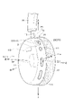
- FIG. 1 is a perspective view showing a state in which a user wears headphones 91, which are the headphones according to the embodiment, on the head H1 and then finely adjusts the wearing position by hand.
- FIG. 2 is a perspective view of the left main body portion 1L of the headphone 91 as seen obliquely from the lower rear left.
- FIG. 3 is a view taken along the arrow Ya in FIG. 2, and is a view of the sound collector 2 provided in the housing 11 of the main body 1L as viewed from outside in the normal direction.
- FIG. 4 is a cross-sectional view at S4-S4 position in FIG.
- FIG. 5 is a cross-sectional view taken along line S5-S5 in FIG. FIG.
- FIG. 6 is a cross-sectional view showing a state in which a finger H2 is in contact with the sound collector 2.
- FIG. 7 is a graph showing the relationship between the frequency of finger contact noise and the sound pressure dB in the headphone 91 and the comparative example.
- FIG. 8 is a perspective view showing a sound collector 2A that is a modification 1 of the sound collector 2.
- FIG. 9 is a perspective view showing a sound collector 2B that is a modification 2 of the sound collector 2.
- FIG. 8 is a perspective view showing a sound collector 2A that is a modification 1 of the sound collector 2.
- FIG. 9 is a perspective view showing a sound collector 2B that is a modification 2 of the sound collector 2.
- the headphone according to the embodiment will be described with the headphone 91 of the example.
- the headphone 91 is an overhead type having a headband 14 and has a hear-through function and a noise canceling function.
- the headphone 91 wirelessly receives an audio signal and outputs audio from a speaker unit SP (see FIG. 2) housed inside the housing 11 .
- FIG. 1 is a perspective view showing a state in which the user finely adjusts the wearing position by hand after wearing the headphones 91 on the head H1.
- Front, back, left, right, up and down directions in the following description are defined as directions indicated by arrows in FIG.
- the headphone 91 includes a pair of left and right body portions 1 , a headband 14 , and a pivot shaft 13 connecting the body portion 1 and the headband 14 .
- the pair of body portions 1 is a set of a body portion 1R to be worn on the right ear and a body portion 1L to be worn on the left ear.
- the headband 14 is placed on the top of the user's head H1a.
- the pivot shaft 13 connects the main body 1 to the end of the headband 14 so as to be swingable within a predetermined angular range. In FIG. 1, only the pivot shaft 13 connected to the body portion 1L is shown.
- main body part 1L and the main body part 1R have bilaterally symmetrical structures, the configuration and shape will be described with the main body part 1L as a representative.
- FIG. 2 is a perspective view of the main body 1L as seen from the rear and diagonally lower left. As shown in FIGS. 1 and 2, the main body 1L has a flat, substantially truncated cone-shaped housing 11 and an ear pad 12 detachably attached to the head-side end of the housing 11 .
- the housing 11 is made of resin and has a substantially flat frustum shape that is substantially circular or elliptical in plan view.
- An example resin is ABS (acrylonitrile-butadiene-styrene).
- the right side of the housing 11 is closed with a baffle board (not shown).
- a speaker unit SP is attached to the baffle board, and sound is output from the speaker unit SP toward the right.
- a substrate portion 113 is housed inside the housing 11 .
- the board section 113 has a communication section, an audio processing section, and a drive section (none of which is shown).
- the communication unit performs wireless communication with an external device and receives an audio signal.
- the audio processing unit appropriately processes the received audio signal and the external sound signal collected by the microphone unit 31 (see FIG. 4) to generate an SP output signal and outputs it to the driving unit.
- the driving section amplifies the SP output signal input from the audio processing section and outputs it to the outside as audio from the speaker unit SP.
- a plurality of operation knobs 111 are exposed and arranged on the side peripheral surface 11a included in the outer surface of the housing 11 for the user to perform finger operations such as power on/off and function switching. It is A pivot shaft 13 is connected to the housing 11 at a connecting portion P1 of the side peripheral surface 11a.
- a sound collector 2 is provided at a portion of the side peripheral surface 11a on the rear side close to the connecting portion P1. The sound collector 2 has a microphone hole 21 .
- FIG. 3 is a view taken along the arrow Ya in FIG. 2 and is a view of the sound collector 2 viewed from outside in the normal direction.
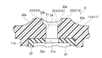
- 4 is a cross-sectional view taken along line S4-S4 in FIG. 3
- FIG. 5 is a cross-sectional view taken along line S5-S5 in FIG.
- the sound collecting part 2 is configured to include a microphone hole 21, a pair of bank parts 22 and 23, and a bottom part 24 in appearance. As shown in FIG. 4, the sound collector 2 includes a microphone box 11b, a microphone unit 31, a microphone case 32, and a cap 112 as the internal structure of the housing 11. As shown in FIG.
- a microphone hole 21 is opened in the side peripheral surface 11a of the housing 11 as a circular through hole having an inner diameter of about 1.5 mm.
- a straight line orthogonal to the direction line CL2H is defined as a thickness orthogonal line CL2Y
- a normal line to the side peripheral surface 11a which passes through the center C21 and is orthogonal to the paper surface is defined as a normal line CL2V.
- the direction in which the thickness orthogonal line CL2Y extends is called the first direction
- the thickness direction line CL2H is called the second direction.
- a projecting portion 2T2 and a projecting portion 2T3 projecting radially outward from the side peripheral surface 11a are formed on the left and right sides of the microphone hole 21, respectively.
- the protruding portion 2T2 is a bank portion 22 that is formed to bulge like a bank
- the protruding portion 2T3 is a bank portion 23 that is formed to bulge like a bank.
- the bank portion 22 and the bank portion 23 are positioned corresponding to the center C21 of the microphone hole 21, which is the position where the thickness direction line CL2H and the thickness orthogonal line CL2Y intersect. becomes height.
- the maximum height of the bank portion 22 and the bank portion 23 is the same, and is about 1.2 mm, for example.
- the bank portion 22 and the bank portion 23 are formed in a generally bilaterally symmetrical shape with respect to the thickness orthogonal line CL2Y in FIG.
- the height Ht (see FIG. 4) of the bank portions 22 and 23 gradually decreases with increasing distance from the microphone hole 21 along the thickness orthogonal line CL2Y.
- the bank portion 22 and the bank portion 23 have widths W2 and W3, which are widths at the maximum height position, of about 0.5 mm, respectively.
- the distance (W-[W2+W3]) at the tip position between the bank portion 22 and the bank portion 23 in the thickness orthogonal line CL2Y direction is approximately 2.5 mm.
- the bank portion 22 and the bank portion 23 are formed parallel to each other in the direction of the thickness orthogonal line CL2Y in FIG.
- the length L is approximately 8.5 mm.
- the width of the position where the height Ht of the bank portion 22 and the bank portion 23 is 0 (zero) in the direction of the thickness direction line CL2H in FIG. 2 is approximately 6.5 mm.
- the bottom portion 24 may be a curved peripheral surface that is continuous with the peripheral surface other than the sound collector 2 without being cut.
- a space surrounded by the bottom portion 24 and the bank portions 22 and 23 is defined as a space V (see FIGS. 3 to 5).
- the bank portions 22 and 23 have steeper inner side surfaces 22b and 23b connected to the bottom portion 24 than outer side surfaces 22a and 23a connected to the left and right outer side peripheral surfaces 11a. slope (nearly vertical).
- the opening edge 21a of the microphone hole 21 is rounded by the R portion 21b so that the opening spreads smoothly instead of the edge.
- the sound collector 2 has a microphone box 11b, a microphone unit 31, a microphone case 32, and a cap 112 on the inner surface of the housing 11.
- the microphone box 11b is a peripheral wall integrally formed with the housing 11 and projecting downward in FIG. 4 in an annular shape.
- the microphone unit 31 has a flat cylindrical shape, and one surface serves as a sound collecting surface 31a for capturing sound.
- a terminal 31c is provided on the rear surface 31b, which is the other surface, and one end of a cord 311 is electrically connected to the terminal 31c. The other end of the cord 311 is connected to a microphone input section (not shown) of the board section 113 .
- the microphone case 32 is made of a sound-insulating material, such as rubber, and is formed in an enveloping shape. By inserting the microphone unit 31 into the inner space of the microphone case 32 so that the sound collecting surface 31a is on the far side, the rear surface 31b except for the vicinity of the terminal 31c is covered and accommodated.
- a microphone assembly 3 is composed of a microphone case 32 and a microphone unit 31 wrapped in the microphone case 32. - ⁇
- the microphone case 32 has an opening 32a formed in the center of the back wall 321 so that the sound collecting surface 31a of the accommodated microphone unit 31 is exposed.
- the microphone case 32, in which the microphone unit 31 is housed is housed in the microphone box 11b with almost no gap.
- the microphone unit 31 can satisfactorily collect external sounds.
- the opening of the microphone box 11b which is the lower end in FIG. 4, is closed with a cap 112 made of resin.
- a through hole 112a is formed in the cap 112, and the cord 311 extends outward through the through hole 112a.
- FIG. 6 is a cross-sectional view showing a state in which the finger H2 gripping the housing 11 is in contact with the sound collector 2. As shown in FIG. 1 , when the headphone 91 having the sound collector 2 described above is gripped by hand, the side peripheral surface 11 a of the housing 11 is brought into contact with the finger.
- FIG. 6 is a cross-sectional view showing a state in which the finger H2 gripping the housing 11 is in contact with the sound collector 2. As shown in FIG.
- the rubbing sound is generated at a position farther from the sound collecting surface 31 a of the microphone unit 31 than the opening edge 21 a of the microphone hole 21 . Therefore, even if a rubbing sound occurs, the sound volume collected by the microphone unit 31 is sufficiently low compared to the case where the bank portions 22 and 23 are not provided.
- the opening edge 21a of the microphone hole 21 is formed with an R portion 21b. Therefore, for example, even if a small finger is pushed between the bank portions 22 and 23 while being tilted and is able to touch the opening edge portion 21a, the generated contact sound is similar to that of the contact sound when the edge portion contacts a sharp edge without a chamfer. Unlike the sound, the external sound is collected by the microphone unit 31 as a less stimulating sound in which the sound in the middle range is attenuated.
- the finger pad Ha of the finger H2 does not reach the microphone hole 21 and does not block the microphone hole 21. ⁇ That is, the internal space of the microphone hole 21 always communicates with the space V between the bank portions 22 and 23 . If the bank portions 22 and 23 were not formed, the microphone hole 21 might be blocked by the finger H2, and in this case, the internal space of the microphone hole 21 would be sealed.
- a soft finger pad H2a is slightly inserted into the microphone hole 21. - ⁇ Therefore, if the finger H2 moves slightly while blocking the microphone hole 21, the amount of penetration of the finger pad H2a into the microphone hole 21 slightly changes. That is, the capacitance inside the microphone hole 21 subtly changes.
- This capacitance change results in a large pressure change, which is collected by the microphone unit 31 as noise.
- a closed space is formed in the microphone hole 21 by closing the microphone hole 21 with the finger pad H2a, and the touch noise caused by the pressure fluctuation caused by the minute positional change of the finger pad H2a is suppressed. does not occur.
- FIG. 7 is a graph showing the relationship between the frequency of touch noise generated when the finger H2 is placed on the sound collecting portion 2 of the housing 11 and the sound pressure for the example and the comparative example.
- An embodiment is a headphone 91 including a housing 11 having a sound collecting portion 2, a bank portion 22 and a bank portion 23, and a microphone hole 21 provided with an R portion 21b.
- a comparative example is a headphone in which the bank portion 22 and the bank portion 23 are not formed, and the microphone hole 21 is opened by merely providing the R portion 21b to the side peripheral surface 11a of the housing 11 . That is, the embodiment differs from the comparative example only in that it has bank portions 22 and 23 .
- the contact state of the finger H2 with the sound collector 2 in the example is the state shown in FIG. is in a state of
- the touch noise characteristic indicated by the solid line of the example has a lower sound pressure than the characteristic of the conventional example indicated by the dashed line in the frequency band from 60 Hz to 10000 Hz.
- the working example is smaller than the comparative example by 30 dB or more at around 300 Hz and by 25 dB or more at around 1000 Hz.
- the headphone 91 has small touch noise even if the microphone hole 21 is opened in the side peripheral surface 11a of the housing 11 .
- the bank portions 22 and 23 of the sound collecting portion 2 may not be protrusions formed in a shape continuous in the circumferential direction.
- the sound collector 2 may be the sound collector 2A of Modified Example 1 shown in FIG. 8 or the sound collector 2B of Modified Example 2 shown in FIG.
- FIG. 8 is a perspective view showing the appearance of the sound collector 2A of Modification 1.
- the sound collecting portion 2A has a projecting portion whose projecting height changes in a wave shape along the circumferential direction (arrow DR1) instead of the bank portions 22 and 23 as the projecting portions 2T2 and 2T3 in the sound collecting portion 2 of the embodiment. 22A and 23A.
- the protrusions 22A and 23A have raised ribs 22Aa to 22Ag and ribs 23Aa to 23Ag extending in the width direction of the housing 11, respectively.
- the height of the ribs 22Ad and 23Ad closest to the microphone hole 21 is the highest, and the height of the ribs farther from the ribs 22Ad and 23Ad is smaller (lower).
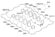
- FIG. 9 is a perspective view showing the appearance of the sound collector 2B of Modification 2.
- the sound collecting part 2B has a plurality of column group parts 22B, 23B arranged along the circumferential direction and projecting instead of the bank parts 22, 23 as the projecting parts 2T2, 2T3 in the embodiment.
- the column group portions 22B and 23B each have a plurality of protruding column portions 22Ba to 22Bf and 23Ba to 23Bf that stand apart from each other in the circumferential direction of the housing 11 (arrow DR2).
- the protruding pillars 22Bc, 22Bd, 23Bc, and 23Bd closest to the microphone hole 21 are the highest, and the pillars farther from these are smaller (lower) in height. .
- the interval between the ribs adjacent in the circumferential direction and the interval between the ribs facing in the direction orthogonal to the circumferential direction are sufficiently small relative to the degree of depression of the finger pad H2a, so that the finger H2 is placed on the sound collecting portion 2A. Even if pressed, the finger pulp H2a does not come into contact with the opening edge 21a of the microphone hole 21 as much as possible.
- the distance between the pillars adjacent in the circumferential direction and the distance between the pillars facing in the direction orthogonal to the circumferential direction are sufficiently small with respect to the degree of deformation of the finger pad H2a, and the sound collecting part 2B is designed so that the finger can be moved to Even if H2 is pressed, the finger pad H2a is designed not to contact the opening edge 21a of the microphone hole 21 as much as possible.
- the headphone 91A equipped with the sound collector 2A of Modified Example 1 and the headphone 91B equipped with the sound collector 2B of Modified Example 2 have small touch noise even when the microphone hole 21 is open to the housing 11.
- the extending direction of the bank portion 22 and the bank portion 23 in the embodiment may not be the circumferential direction, but may be a direction orthogonal to the circumferential direction or a direction oblique to the circumferential direction.
- the embodiment, modified example 1, and modified example 2 can be freely combined within a possible range.
- the external shape of the housing 11 does not have to be a frustum shape, and may be, for example, a bowl shape.
- the microphone hole 21 is not limited to being opened on the side peripheral surface 11a, which is the outer surface, and may be opened on another outer surface (upper surface).
- the microphone hole 21 is a hole that opens to the outer surface.
Landscapes
- Physics & Mathematics (AREA)
- Engineering & Computer Science (AREA)
- Acoustics & Sound (AREA)
- Signal Processing (AREA)
- Headphones And Earphones (AREA)
- Details Of Audible-Bandwidth Transducers (AREA)
Abstract
ヘッドホン(91)は、スピーカユニット(SP)と、マイクユニット(31)と、スピーカユニット(SP)及びマイクユニット(31)を収容するハウジング(11)と、外音をマイクユニット(31)で集音するためにハウジング(11)の外面(11a)に開口したマイク孔(21)とを有する本体部(1)と、端部に本体部(1)が連結されたヘッドバンド(14)と、を備える。本体部(1)は、外面(11a)においてマイク孔(21)を挟み第1の方向(CL2Y)に沿って外面(11a)から突出して形成された一対の突出部(2T2,2T3)を有する。
Description
本開示は、ヘッドホンに関する。
ヘッドホンとして、ヒアスルー機能又はノイズキャンセル機能を有するものがある。ヒアスルー機能は、聴取目的の音声と外音とを混合して聴取できる、或いは聴取目的の音声を一時的にミュートして外音のみを聴取できる機能である。また、ノイズキャンセル機能は、漏入する外音を打ち消して、実質的に聴取目的の音声のみを聴取できる機能である。
ヒアスルー機能又はノイズキャンセル機能を有するヘッドホンは、外音を集音するマイクを備えている。
ヒアスルー機能又はノイズキャンセル機能を有するヘッドホンは、外音を集音するマイクを備えている。
特許文献1には、第2実施形態として、外音である周辺音を集音するマイクをハウジングに備えたヘッドホンが記載されている。マイクは、特許文献1の図5に示されるように、ハウジングの外周部に備えられている。
特許文献1の第2実施形態のようなハウジングにマイクを有する構造の場合、通常、マイクはハウジングの内側に配置され、ハウジングにはマイクと外部空間とを連通する貫通孔であるマイク孔を設けるのが一般的である。すなわち、ハウジングの外面にはマイク孔が開口している。
一方、ハウジングにおける外音を集音する位置は、ヘッドホンの装着者の呼気音及び装着者の動作に伴って生じる音の影響をできるだけ受けにくい位置とすることが望まれる。そのため、一般的に、マイクはハウジングの上部に配置される。例えば、ヘッドホンが頭頂部に掛けるヘッドバンドを有するいわゆるオーバーヘッド型の場合、ハウジングにおけるマイクの配置位置はヘッドバンドの連結部の近傍とされる。
一方、ハウジングにおける外音を集音する位置は、ヘッドホンの装着者の呼気音及び装着者の動作に伴って生じる音の影響をできるだけ受けにくい位置とすることが望まれる。そのため、一般的に、マイクはハウジングの上部に配置される。例えば、ヘッドホンが頭頂部に掛けるヘッドバンドを有するいわゆるオーバーヘッド型の場合、ハウジングにおけるマイクの配置位置はヘッドバンドの連結部の近傍とされる。
また、ハウジングの外面は、頭部に装着したヘッドホンの装着位置を調整する場合などにおいて、ハウジングを掴む装着者の手の指が特に掛かりやすい場所である。
一般に、マイク孔に指が接触すると、耳障りな大きいタッチノイズが発生することが知られており、このタッチノイズを小さくすることが望まれている。
一般に、マイク孔に指が接触すると、耳障りな大きいタッチノイズが発生することが知られており、このタッチノイズを小さくすることが望まれている。
そこで、本実施形態は、ハウジングの外面に開口するマイク孔を有してもタッチノイズが小さいヘッドホンを提供することを目的とする。
本実施形態によれば、スピーカユニットと、マイクユニットと、前記スピーカユニット及び前記マイクユニットを収容するハウジングと、外音を前記マイクユニットで集音するために前記ハウジングの外面に開口したマイク孔とを有する本体部と、端部に前記本体部が連結されたヘッドバンドと、を備え、前記本体部は、前記外面において前記マイク孔を挟み第1の方向に沿って前記外面から突出して形成された一対の突出部を有しているヘッドホンが提供される。
実施形態のヘッドホンよれば、ハウジングの外面に開口するマイク孔を有してもタッチノイズが小さい、という効果が得られる。
実施形態に係るヘッドホンを、実施例のヘッドホン91により説明する。ヘッドホン91は、ヘッドバンド14を有するオーバーヘッド型であり、ヒアスルー機能及びノイズキャンセル機能を備えている。ヘッドホン91は、無線で音声信号を受信し、ハウジング11の内部に収容したスピーカユニットSP(図2参照)から音声を出力する。
図1は、使用者がヘッドホン91を頭部H1に装着した後、装着位置を手で微調整している状態を示す斜視図である。以下の説明における前後左右上下の各方向を、図1に矢印で示された方向に規定する。
ヘッドホン91は、左右一対の本体部1,ヘッドバンド14,及び本体部1とヘッドバンド14とを連結するピボットシャフト13を備えている。
一対の本体部1は、右耳に宛がう本体部1Rと左耳に宛がう本体部1Lとの組である。ヘッドバンド14は、使用者の頭頂部H1aに載せられる。ピボットシャフト13は、ヘッドバンド14の端部に対し所定の角度範囲で揺動可能なように本体部1を連結している。図1では、本体部1Lに連結するピボットシャフト13のみ示されている。
一対の本体部1は、右耳に宛がう本体部1Rと左耳に宛がう本体部1Lとの組である。ヘッドバンド14は、使用者の頭頂部H1aに載せられる。ピボットシャフト13は、ヘッドバンド14の端部に対し所定の角度範囲で揺動可能なように本体部1を連結している。図1では、本体部1Lに連結するピボットシャフト13のみ示されている。
本体部1L及び本体部1Rは、左右対称構造なので、構成及び形状は、代表として本体部1Lによって説明する。
図2は、本体部1Lを後方斜め左下方から見た斜視図である。
図1及び図2に示されるように、本体部1Lは、扁平の略円錐台状のハウジング11と、ハウジング11における頭部側となる端部に着脱自在に装着されたイヤパッド12とを有する。
図1及び図2に示されるように、本体部1Lは、扁平の略円錐台状のハウジング11と、ハウジング11における頭部側となる端部に着脱自在に装着されたイヤパッド12とを有する。
図2において、ハウジング11は、樹脂によって平面視で概ね円形又は楕円形となる扁平の略錐台状に形成されている。樹脂例はABS(アクリロニトリル・ブタジエン・スチレン)である。
ハウジング11の右面はバッフルボード(不図示)で塞がれている。バッフルボードにはスピーカユニットSPが取り付けられており、スピーカユニットSPから右方に向け音声が出力される。ハウジング11の内部には、基板部113が収容されている。
ハウジング11の右面はバッフルボード(不図示)で塞がれている。バッフルボードにはスピーカユニットSPが取り付けられており、スピーカユニットSPから右方に向け音声が出力される。ハウジング11の内部には、基板部113が収容されている。
基板部113は、通信部,音声処理部,及び駆動部(いずれも不図示)を有する。通信部は、外部機器と無線通信を行い、音声信号を受信する。音声処理部は、受信した音声信号と、マイクユニット31(図4参照)で集音された外音の信号とを適宜処理してSP出力信号を生成し、駆動部に向け出力する。駆動部は、音声処理部から入来したSP出力信号を増幅し、スピーカユニットSPから音声として外部に出力させる。
図2に示されるように、ハウジング11の外面に含まれる側周面11aには、使用者が電源入切、機能切替、などを指操作するための複数の操作ノブ111が、露出して配置されている。
ハウジング11には、ピボットシャフト13が、側周面11aの連結部P1で連結されている。
側周面11aにおける連結部P1に近接する後方側の部位には、集音部2が設けられている。集音部2はマイク孔21を有する。
ハウジング11には、ピボットシャフト13が、側周面11aの連結部P1で連結されている。
側周面11aにおける連結部P1に近接する後方側の部位には、集音部2が設けられている。集音部2はマイク孔21を有する。
集音部2について、図3~図5を参照して説明する。
図3は、図2の矢視Ya図であって、集音部2を法線方向の外方から見た図である。図4は、図3におけるS4-S4位置での断面図であり、図5は、図3におけるS5-S5位置での断面図である。
図3は、図2の矢視Ya図であって、集音部2を法線方向の外方から見た図である。図4は、図3におけるS4-S4位置での断面図であり、図5は、図3におけるS5-S5位置での断面図である。
集音部2は、外観上、マイク孔21,一対の土手部22,23,及び底部24,を含んで構成されている。また、図4に示されるように、集音部2は、ハウジング11の内部構造として、マイクボックス11b,マイクユニット31,マイクケース32,キャップ112を含んで構成されている。
ハウジング11の側周面11aには、マイク孔21が内径約1.5mmの円形の貫通孔として開口している。
以下の説明の便宜のため、図3におけるマイク孔21の中心を中心C21としたときに、中心C21を通るハウジング11の厚さ方向の直線を厚さ方向線CL2Hとし、中心C21を通り厚さ方向線CL2Hに直交する直線を厚さ直交線CL2Yとし、中心C21を通り紙面に直交する側周面11aの法線を法線CL2Vとする。
厚さ直交線CL2Yの延びる方向を第1の方向と称し、厚さ方向線CL2Hを第2の方向と称する。
以下の説明の便宜のため、図3におけるマイク孔21の中心を中心C21としたときに、中心C21を通るハウジング11の厚さ方向の直線を厚さ方向線CL2Hとし、中心C21を通り厚さ方向線CL2Hに直交する直線を厚さ直交線CL2Yとし、中心C21を通り紙面に直交する側周面11aの法線を法線CL2Vとする。
厚さ直交線CL2Yの延びる方向を第1の方向と称し、厚さ方向線CL2Hを第2の方向と称する。
マイク孔21を挟んでその左側と右側とには、それぞれ側周面11aから径方向の外方に突出する突出部2T2と突出部2T3とが形成されている。この例において突出部2T2は土手状に隆起形成された土手部22であり、突出部2T3は土手状に隆起形成された土手部23である。
土手部22及び土手部23は、厚さ方向線CL2Hと厚さ直交線CL2Yとが交わる位置であるマイク孔21の中心C21に対応した位置で、側周面11aからの突出量が最も大きい最大高さとなる。最大高さは、土手部22と土手部23とで同じであり、例えば約1.2mmである。
土手部22と土手部23とは、図3において厚さ直交線CL2Yに対し概ね左右対称形状に形成されている。
土手部22及び土手部23は、厚さ方向線CL2Hと厚さ直交線CL2Yとが交わる位置であるマイク孔21の中心C21に対応した位置で、側周面11aからの突出量が最も大きい最大高さとなる。最大高さは、土手部22と土手部23とで同じであり、例えば約1.2mmである。
土手部22と土手部23とは、図3において厚さ直交線CL2Yに対し概ね左右対称形状に形成されている。
土手部22,23の高さHt(図4参照)は、厚さ直交線CL2Yに沿ってマイク孔21から離れるに従って徐々に低くなっている。
図3において、土手部22及び土手部23は、最大高さ位置の幅である幅W2及び幅W3がそれぞれ約0.5mmである。また、土手部22と土手部23との厚さ直交線CL2Y方向における先端位置での間隔(W-〔W2+W3〕)は、概ね2.5mmである。
図3において、土手部22及び土手部23は、最大高さ位置の幅である幅W2及び幅W3がそれぞれ約0.5mmである。また、土手部22と土手部23との厚さ直交線CL2Y方向における先端位置での間隔(W-〔W2+W3〕)は、概ね2.5mmである。
図3の厚さ直交線CL2Y方向において、土手部22と土手部23とは平行に形成され、土手部22及び土手部23の高さHtが0(ゼロ)になる位置の、図3における長さLは、約8.5mmである。
図2の厚さ方向線CL2H方向において、土手部22及び土手部23の高さHtが0(ゼロ)になる位置の幅は、約6.5mmである。
土手部22と土手部23との間のマイク孔21の開口部分を含む領域である底部24は、図4に示されるように、ハウジング11の側周面11aを、平面状となるようにわずかにカットして形成された部位である。底部24は、カットされずに集音部2以外の周面と連続する曲面状の周面であってもよい。
底部24と、土手部22及び土手部23とで囲まれた空間を空間Vとする(図3~5参照)。
図2の厚さ方向線CL2H方向において、土手部22及び土手部23の高さHtが0(ゼロ)になる位置の幅は、約6.5mmである。
土手部22と土手部23との間のマイク孔21の開口部分を含む領域である底部24は、図4に示されるように、ハウジング11の側周面11aを、平面状となるようにわずかにカットして形成された部位である。底部24は、カットされずに集音部2以外の周面と連続する曲面状の周面であってもよい。
底部24と、土手部22及び土手部23とで囲まれた空間を空間Vとする(図3~5参照)。
図3及び図5に示されるように、土手部22,23は、左右外側の側周面11aに接続する外側面22a,23aよりも、底部24に接続する内側面22b,23bの方が急峻な斜面(垂直に近い斜面)となっている。
マイク孔21の開口縁部21aには、R部21bによるR付けが施されて、エッジではなく滑らかに広がるように開口している。
図4に示されるように、集音部2は、ハウジング11の内面に、マイクボックス11b,マイクユニット31,マイクケース32,及びキャップ112を有する。
マイクボックス11bは、ハウジング11と一体的に、図4の下方に向け円環状に突出形成した周壁である。
マイクユニット31は、扁平の円筒状を呈し、一方の面が、音を取り込む集音面31aとなっている。他方の面である背面31bには端子31cを有し、端子31cにはコード311の一端側が電気的に接続されている。コード311の他端側は、基板部113のマイク入力部(不図示)に接続されている。
マイクボックス11bは、ハウジング11と一体的に、図4の下方に向け円環状に突出形成した周壁である。
マイクユニット31は、扁平の円筒状を呈し、一方の面が、音を取り込む集音面31aとなっている。他方の面である背面31bには端子31cを有し、端子31cにはコード311の一端側が電気的に接続されている。コード311の他端側は、基板部113のマイク入力部(不図示)に接続されている。
マイクケース32は、ゴムなどの遮音性を有する材料で円包状に形成されている。マイクケース32の内側空間に、マイクユニット31を集音面31aが奥側となるように入れ込むことで背面31bの端子31c近傍を除き覆われて収容される。マイクケース32と、マイクケース32に包まれたマイクユニット31とでマイクアッセンブリ3が構成される。
マイクケース32は、奥壁部321の中央に開口部32aが形成されており、収容したマイクユニット31の集音面31aが露出するようになっている。
マイクケース32は、マイクユニット31を収容した状態でマイクボックス11bに、ほぼ隙間なく収められている。
そのため、ハウジング11内のスピーカユニットSPなどからの音は、マイクケース32で遮音されてマイクユニット31にほとんど到達せず、マイクユニット31は、マイク孔21を除き音響的に遮蔽されている。
これにより、マイクユニット31は、外音を良好に集音することができる。
マイクケース32は、奥壁部321の中央に開口部32aが形成されており、収容したマイクユニット31の集音面31aが露出するようになっている。
マイクケース32は、マイクユニット31を収容した状態でマイクボックス11bに、ほぼ隙間なく収められている。
そのため、ハウジング11内のスピーカユニットSPなどからの音は、マイクケース32で遮音されてマイクユニット31にほとんど到達せず、マイクユニット31は、マイク孔21を除き音響的に遮蔽されている。
これにより、マイクユニット31は、外音を良好に集音することができる。
マイクボックス11bにおける図4の下端となる開口部は、樹脂で形成されたキャップ112によって塞がれている。キャップ112には貫通孔112aが形成さており、コード311は貫通孔112aを通して外側に延出する。
図4に示されるように、外音は、空間Vからマイク孔21に進入し、マイク孔21を通過した後、マイクケース32の開口部32aを通過し、マイクユニット31の集音面31aからその内部に進入して集音される。
上述の集音部2を備えたヘッドホン91は、図1に示されるように、ハウジング11を手で掴んだときに、ハウジング11の側周面11aに指が接触する。
図6は、ハウジング11を掴む指H2がちょうど集音部2に掛かって接触した状態を示す断面図である。
図6は、ハウジング11を掴む指H2がちょうど集音部2に掛かって接触した状態を示す断面図である。
指H2の指腹部H2aが土手部22,23に乗る状態となって、さらに指H2にハウジング11を掴む強い力が加わると、柔らかい指腹部H2aが土手部22,23を押し付けて凹む。この状態で、一対の土手部22,23の間隔は指腹部H2aの凹み具合に対して十分に狭いので、指腹部H2aがマイク孔21の開口縁部21aに接触することはない。すなわち、マイク孔21に指腹部H2aが接触しないので、マイク孔21への接触により生じるタッチノイズは実質的に生じない。
また、図6に示される状態で指H2が動かされて指腹部H2aが摺動した場合、擦れ音が発生するが、その擦れ音は土手部22,23の頂部で生じる。すなわち、擦れ音の発生位置は、マイクユニット31の集音面31aに対しマイク孔21の開口縁部21aよりも遠い位置にある。そのため、仮に擦れ音が生じても、マイクユニット31に集音される音量は、土手部22,23がない場合と比べて十分小さい音量となる。
また、マイク孔21の開口縁部21aにはR部21bが形成されている。そのため、例えば小さい指が土手部22,23の間に傾けられながら押し込まれて開口縁部21aに接触できたとしても、生じる接触音は、縁部が面取りのない鋭いエッジに接触した場合の接触音とは異なり、外音は、中音域の音が減衰した聴感上で刺激の少ない音としてマイクユニット31に集音される。
また、ヘッドホン91は、ハウジング11に土手部22,23が形成されていることにより、指H2の指腹Haがマイク孔21に届かず、マイク孔21を塞ぐことはない。すなわち、マイク孔21の内部空間は、常に土手部22,23の間の空間Vと連通している。
仮に土手部22,23が形成されていないと、指H2によってマイク孔21が塞がれる可能性があり、この場合、マイク孔21の内部空間が密閉される。マイク孔21には柔らかい指腹部H2aが若干入り込んでいる。
そのため、この指H2がマイク孔21を塞いだままが若干動くと、マイク孔21に指腹部H2aの入り込み量が微妙に変化する。すなわち、マイク孔21内の容量が微妙に変化する。この容量変化は大きな圧力変化となってマイクユニット31にノイズとして集音されてしまう。
ヘッドホン91は、このような、マイク孔21が指腹部H2aで塞がれることでマイク孔21内に密閉空間が形成され、指腹部H2aの微小の位置変化に伴う圧力変動に由来するタッチノイズは生じない。
仮に土手部22,23が形成されていないと、指H2によってマイク孔21が塞がれる可能性があり、この場合、マイク孔21の内部空間が密閉される。マイク孔21には柔らかい指腹部H2aが若干入り込んでいる。
そのため、この指H2がマイク孔21を塞いだままが若干動くと、マイク孔21に指腹部H2aの入り込み量が微妙に変化する。すなわち、マイク孔21内の容量が微妙に変化する。この容量変化は大きな圧力変化となってマイクユニット31にノイズとして集音されてしまう。
ヘッドホン91は、このような、マイク孔21が指腹部H2aで塞がれることでマイク孔21内に密閉空間が形成され、指腹部H2aの微小の位置変化に伴う圧力変動に由来するタッチノイズは生じない。
図7は、ハウジング11の集音部2に対し指H2を掛けた状態で発生するタッチノイズの周波数と音圧との関係を、実施例と比較例とについて示したグラフである。
実施例は、集音部2に土手部22及び土手部23と、R部21bを付与したマイク孔21とを有するハウジング11を備えたヘッドホン91である。
比較例は、土手部22及び土手部23が形成されてなくハウジング11の側周面11aに単にR部21bを付与したマイク孔21が開口しているヘッドホンである。すなわち、実施例は、比較例に対し、土手部22及び土手部23を有する点のみで異なる。
実施例は、集音部2に土手部22及び土手部23と、R部21bを付与したマイク孔21とを有するハウジング11を備えたヘッドホン91である。
比較例は、土手部22及び土手部23が形成されてなくハウジング11の側周面11aに単にR部21bを付与したマイク孔21が開口しているヘッドホンである。すなわち、実施例は、比較例に対し、土手部22及び土手部23を有する点のみで異なる。
実施例における指H2の集音部2への接触状態は、図6に示される状態であり、比較例における指H2は、不図示であるがマイク孔21の開口縁部21aに指H2が接触している状態である。
図7に示されるように、実施例の実線で示されるタッチノイズの特性は、60Hzから10000Hzまでの周波数帯域において、破線で示される従来例の特性よりも小さい音圧になっていることがわかる。特に、実施例は、300Hz前後で30dB以上、1000Hz前後で25dB以上比較例より小さくなっており、土手部22,23を設けることによるタッチノイズの音圧低減効果が顕著である。
以上詳述したように、ヘッドホン91は、ハウジング11の側周面11aにマイク孔21が開口していてもタッチノイズが小さい。
以上詳述した実施例は、その構成に限定されるものではなく、本開示の要旨を逸脱しない範囲において変形した変形例としてもよい。
集音部2の土手部22,23は、周方向に連続した形状で形成された突部でなくてもよい。集音部2は、図8に示される変形例1の集音部2A、或いは図9に示される変形例2の集音部2Bであってもよい。
図8は、変形例1の集音部2Aの外観を示す斜視図である。集音部2Aは、実施例の集音部2における突出部2T2,2T3として、土手部22,23の替わりに、周方向(矢印DR1)に沿って突出高さが波状に変化する突状部22A,23Aを有している。
突状部22A及び突状部23Aは、それぞれハウジング11の幅方向に延びるように隆起したリブ22Aa~22Ag及びリブ23Aa~23Agを有する。
突状部22A及び突状部23Aは、マイク孔21に最も近いリブ22Ad,23Adの高さが最も高く、リブ22Ad,23Adから遠いリブほど高さが小さく(低く)なっている。
突状部22A及び突状部23Aは、それぞれハウジング11の幅方向に延びるように隆起したリブ22Aa~22Ag及びリブ23Aa~23Agを有する。
突状部22A及び突状部23Aは、マイク孔21に最も近いリブ22Ad,23Adの高さが最も高く、リブ22Ad,23Adから遠いリブほど高さが小さく(低く)なっている。
図9は、変形例2の集音部2Bの外観を示す斜視図である。集音部2Bは、実施例における突出部2T2,2T3として、土手部22,23の替わりに、周方向に沿って並び突出する複数の柱群部22B,23Bを有している。
柱群部22B,23Bは、それぞれハウジング11の周方向(矢印DR2)に離隔して突出するよう立設された複数の突柱部22Ba~22Bf,23Ba~23Bfを有する。
柱群部22B及び柱群部23Bは、マイク孔21に最も近い突柱部22Bc,22Bd,23Bc,23Bdの高さが最も高く、これらから遠い柱部ほど高さが小さく(低く)なっている。
柱群部22B,23Bは、それぞれハウジング11の周方向(矢印DR2)に離隔して突出するよう立設された複数の突柱部22Ba~22Bf,23Ba~23Bfを有する。
柱群部22B及び柱群部23Bは、マイク孔21に最も近い突柱部22Bc,22Bd,23Bc,23Bdの高さが最も高く、これらから遠い柱部ほど高さが小さく(低く)なっている。
集音部2Aは、周方向に隣接するリブ同士の間隔及び周方向と直交する方向に対向するリブ同士の間隔が、指腹部H2aの凹み度合に対し十分小さく、集音部2Aに指H2が押し付けられても指腹部H2aがマイク孔21の開口縁部21aにできるだけ接触しないようになっている。
集音部2Bは、周方向に隣接する柱部同士の間隔及び周方向と直交する方向に対向する柱部同士の間隔が、指腹部H2aの変形度合に対し十分小さく、集音部2Bに指H2が押し付けられても指腹部H2aがマイク孔21の開口縁部21aにできるだけ接触しないようになっている。
集音部2Bは、周方向に隣接する柱部同士の間隔及び周方向と直交する方向に対向する柱部同士の間隔が、指腹部H2aの変形度合に対し十分小さく、集音部2Bに指H2が押し付けられても指腹部H2aがマイク孔21の開口縁部21aにできるだけ接触しないようになっている。
これにより、変形例1の集音部2Aを備えたヘッドホン91A及び変形例2の集音部2Bを備えたヘッドホン91Bは、マイク孔21がハウジング11に開口していてもタッチノイズが小さい。
実施例における土手部22及び土手部23の延在方向は、周方向でなくてもよく、周方向に直交する方向或いは周方向に斜向する方向であってもよい。変形例2におけるリブ22Aa~22Ag及びリブ23Aa~23Ag、並びに、変形例3における突柱部22Ba~22Bf及び突柱部23Ba~23Bfについても同様である。
実施例,変形例1,及び変形例2は、可能な範囲で自由に組み合わせることができる。
ハウジング11の外形形状は錐台状でなくてもよく、例えば椀状であってもよい。マイク孔21は、ハウジング11が錐台状の場合、外面である側周面11aに開口するものに限定されず、他の外面(上面)に開口していてもよい。マイク孔21は、ハウジング11が椀状の場合、外面に開口する孔となる。
ハウジング11の外形形状は錐台状でなくてもよく、例えば椀状であってもよい。マイク孔21は、ハウジング11が錐台状の場合、外面である側周面11aに開口するものに限定されず、他の外面(上面)に開口していてもよい。マイク孔21は、ハウジング11が椀状の場合、外面に開口する孔となる。
特願2021-047161号(出願日:2021年3月22日)の全内容は、ここに援用される。
Claims (9)
- スピーカユニットと、マイクユニットと、前記スピーカユニット及び前記マイクユニットを収容するハウジングと、外音を前記マイクユニットで集音するために前記ハウジングの外面に開口したマイク孔とを有する本体部と、
端部に前記本体部が連結されたヘッドバンドと、
を備え、
前記本体部は、前記外面において前記マイク孔を挟み第1の方向に沿って前記外面から突出して形成された一対の突出部を有しているヘッドホン。 - 前記一対の突出部のそれぞれは、前記マイク孔から離れるに従って高さが小さくなるよう土手状に形成された土手部である請求項1記載のヘッドホン。
- 前記一対の突出部のそれぞれは、前記マイク孔から離れるに従って高さが小さくなるよう前記第1の方向と直交する第2の方向に延びて隆起した複数のリブの群である請求項1記載のヘッドホン。
- 前記一対の突出部のそれぞれは、前記マイク孔から離れるに従って高さが小さくなるよう立設された複数の突柱部の群である請求項1記載のヘッドホン。
- 前記一対の突出部は、平行に形成されている請求項1~4のいずれか1項に記載のヘッドホン。
- 前記ハウジングは錐台状であり、
前記マイク孔は、前記ハウジングの前記錐台状の側周面に開口している請求項1~4のいずれか1項に記載のヘッドホン。 - 前記マイク孔の開口縁部には、前記マイク孔から前記ハウジングに向かって滑らかに広がるR部が形成されている請求項1に記載のヘッドホン。
- 前記ハウジングは錐台状であり、
前記土手部は、前記ハウジングの前記錐台状の側周面に接続する外側面よりも、一対の前記土手部の間の領域であって、前記マイク孔の開口部分を含む領域である底部に接続する内側面の方が急峻な斜面となっている請求項2に記載のヘッドホン。 - 前記マイクユニットを覆うマイクケースをさらに備え、
前記マイクケースは、ゴムで形成され、前記マイクユニットの集音面が露出する開口部を有し、前記マイクユニットを収容した状態で前記ハウジングに隙間なく収められる請求項1に記載のヘッドホン。
Applications Claiming Priority (2)
| Application Number | Priority Date | Filing Date | Title |
|---|---|---|---|
| JP2021047161A JP7552465B2 (ja) | 2021-03-22 | 2021-03-22 | ヘッドホン |
| JP2021-047161 | 2021-03-22 |
Publications (1)
| Publication Number | Publication Date |
|---|---|
| WO2022201689A1 true WO2022201689A1 (ja) | 2022-09-29 |
Family
ID=83396716
Family Applications (1)
| Application Number | Title | Priority Date | Filing Date |
|---|---|---|---|
| PCT/JP2021/047179 Ceased WO2022201689A1 (ja) | 2021-03-22 | 2021-12-21 | ヘッドホン |
Country Status (2)
| Country | Link |
|---|---|
| JP (2) | JP7552465B2 (ja) |
| WO (1) | WO2022201689A1 (ja) |
Citations (5)
| Publication number | Priority date | Publication date | Assignee | Title |
|---|---|---|---|---|
| JPH0210689U (ja) * | 1988-07-06 | 1990-01-23 | ||
| JPH08111704A (ja) * | 1994-10-12 | 1996-04-30 | Kyocera Corp | 携帯無線電話機 |
| JP2003333152A (ja) * | 2002-03-05 | 2003-11-21 | Seiko Instruments Inc | ウエアラブル電子機器 |
| JP2005318127A (ja) * | 2004-04-27 | 2005-11-10 | Fujitsu Ltd | 携帯型通信端末装置 |
| JP2019087869A (ja) * | 2017-11-07 | 2019-06-06 | ヤマハ株式会社 | 音響出力装置 |
Family Cites Families (4)
| Publication number | Priority date | Publication date | Assignee | Title |
|---|---|---|---|---|
| US7367422B2 (en) * | 2004-05-21 | 2008-05-06 | Brookstone Purchasing. Inc. | System and method for providing passive noise reduction |
| JP2010109799A (ja) * | 2008-10-31 | 2010-05-13 | Audio Technica Corp | ノイズキャンセルヘッドホン |
| CN210327919U (zh) * | 2019-11-13 | 2020-04-14 | 刘楚雨 | 一种具有通讯功能的隔音耳机 |
| CN210868108U (zh) * | 2019-12-18 | 2020-06-26 | 深圳市冠旭电子股份有限公司 | 一种头戴式耳机 |
-
2021
- 2021-03-22 JP JP2021047161A patent/JP7552465B2/ja active Active
- 2021-12-21 WO PCT/JP2021/047179 patent/WO2022201689A1/ja not_active Ceased
-
2024
- 2024-08-30 JP JP2024148598A patent/JP2024164255A/ja active Pending
Patent Citations (5)
| Publication number | Priority date | Publication date | Assignee | Title |
|---|---|---|---|---|
| JPH0210689U (ja) * | 1988-07-06 | 1990-01-23 | ||
| JPH08111704A (ja) * | 1994-10-12 | 1996-04-30 | Kyocera Corp | 携帯無線電話機 |
| JP2003333152A (ja) * | 2002-03-05 | 2003-11-21 | Seiko Instruments Inc | ウエアラブル電子機器 |
| JP2005318127A (ja) * | 2004-04-27 | 2005-11-10 | Fujitsu Ltd | 携帯型通信端末装置 |
| JP2019087869A (ja) * | 2017-11-07 | 2019-06-06 | ヤマハ株式会社 | 音響出力装置 |
Also Published As
| Publication number | Publication date |
|---|---|
| JP7552465B2 (ja) | 2024-09-18 |
| JP2024164255A (ja) | 2024-11-26 |
| JP2022146278A (ja) | 2022-10-05 |
Similar Documents
| Publication | Publication Date | Title |
|---|---|---|
| JP3240241U (ja) | 開放式耳掛け型ウェアラブル発音装置 | |
| US12120478B2 (en) | Open earphone | |
| US9473845B2 (en) | Active noise cancelling ear phone system | |
| TWI501654B (zh) | 具有經控制之聲音洩漏埠之耳機 | |
| JP5367658B2 (ja) | イヤースピーカ | |
| US20250113136A1 (en) | Acoustic device | |
| CN101090687B (zh) | 听力保护器 | |
| US20240147146A1 (en) | Earphones | |
| JP5441164B2 (ja) | ヘッドホン | |
| CN106454575B (zh) | 头戴式消噪耳机 | |
| JP7509141B2 (ja) | 音響出力装置 | |
| US8351633B2 (en) | Noise cancelling microphone with wind shield | |
| JP4206599B2 (ja) | マイクロホン | |
| WO2022201689A1 (ja) | ヘッドホン | |
| EP3367696A1 (en) | Flexible earphone cover for earphones with sensors | |
| EP3122065B1 (en) | Noise-cancelling headphone | |
| TWM632340U (zh) | 耳機 | |
| CN214627307U (zh) | 一种主动降噪蓝牙耳机 | |
| CN115604616A (zh) | 耳机结构 | |
| CN217470252U (zh) | 一种入耳耳机使用的小型扬声器 | |
| KR102808170B1 (ko) | 음향 손실 최소화 왁스가드 이어팁 | |
| JP7051271B1 (ja) | 騒音軽減マイクスポンジ | |
| JP2011135480A (ja) | 接話型コンデンサマイクロホン | |
| KR20190142029A (ko) | 이어팁 | |
| CN208623870U (zh) | 一种头戴式耳机的降噪结构 |
Legal Events
| Date | Code | Title | Description |
|---|---|---|---|
| 121 | Ep: the epo has been informed by wipo that ep was designated in this application |
Ref document number: 21933279 Country of ref document: EP Kind code of ref document: A1 |
|
| DPE1 | Request for preliminary examination filed after expiration of 19th month from priority date (pct application filed from 20040101) | ||
| NENP | Non-entry into the national phase |
Ref country code: DE |
|
| 122 | Ep: pct application non-entry in european phase |
Ref document number: 21933279 Country of ref document: EP Kind code of ref document: A1 |