WO2022201671A1 - 緩衝器 - Google Patents
緩衝器 Download PDFInfo
- Publication number
- WO2022201671A1 WO2022201671A1 PCT/JP2021/046449 JP2021046449W WO2022201671A1 WO 2022201671 A1 WO2022201671 A1 WO 2022201671A1 JP 2021046449 W JP2021046449 W JP 2021046449W WO 2022201671 A1 WO2022201671 A1 WO 2022201671A1
- Authority
- WO
- WIPO (PCT)
- Prior art keywords
- valve
- piston
- cylinder
- chamber
- damping force
- Prior art date
- Legal status (The legal status is an assumption and is not a legal conclusion. Google has not performed a legal analysis and makes no representation as to the accuracy of the status listed.)
- Ceased
Links
Images


Classifications
-
- F—MECHANICAL ENGINEERING; LIGHTING; HEATING; WEAPONS; BLASTING
- F16—ENGINEERING ELEMENTS AND UNITS; GENERAL MEASURES FOR PRODUCING AND MAINTAINING EFFECTIVE FUNCTIONING OF MACHINES OR INSTALLATIONS; THERMAL INSULATION IN GENERAL
- F16F—SPRINGS; SHOCK-ABSORBERS; MEANS FOR DAMPING VIBRATION
- F16F9/00—Springs, vibration-dampers, shock-absorbers, or similarly-constructed movement-dampers using a fluid or the equivalent as damping medium
- F16F9/32—Details
- F16F9/48—Arrangements for providing different damping effects at different parts of the stroke
Definitions
- the present disclosure relates to a shock absorber that is mounted on a vehicle such as a four-wheeled vehicle and that is preferably used to damp vibration of the vehicle.
- Patent Document 1 discloses a damping force generator provided between a piston-side oil chamber and a rod-side oil chamber of a hydraulic shock absorber. This damping force generating device is provided with a through hole that communicates between the piston-side oil chamber and the rod-side oil chamber. A needle is provided at the tip of the piston rod and can be advanced and retracted into the through hole of the damping force generator.
- An object of one embodiment of the present invention is to generate damping force in the normal stroke range during the compression stroke, and to generate even higher damping force when the piston approaches the bottom side of the cylinder beyond the normal stroke range.
- a shock absorber includes a first cylinder filled with a working fluid, and slidably fitted in the first cylinder to divide the inside of the first cylinder into a rod-side chamber and a bottom-side chamber.
- a first piston a piston rod connected to the first piston, a first valve member provided in the bottom side chamber and having a first valve that generates a damping force during a compression stroke, and an outer peripheral side of the first cylinder.
- a reservoir chamber formed between the first cylinder and the second cylinder; and the first piston moving toward the first valve member in the first cylinder.
- a stopper mechanism that operates during a contraction stroke of the piston rod, the stopper mechanism comprising a second valve member provided between the first piston and the first valve member; and the first valve.
- An intermediate chamber formed between a member and the second valve member, a first adjustment member that moves with the first piston with respect to the first cylinder, and a relative position of the first adjustment member determine the bottom side chamber.
- a second adjusting member for opening and closing a bypass passage connecting the first piston and the intermediate chamber; and a second valve provided in the second valve member for generating a damping force during a contraction stroke.
- the first damping force in the compression stroke, in addition to generating the first damping force in the first stroke range, when the piston approaches the bottom side of the cylinder beyond the first stroke range, the first damping force is generated.
- a second damping force higher than the damping force can be generated.
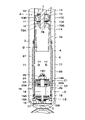
- FIG. 1 is a longitudinal sectional view showing a hydraulic shock absorber according to a first embodiment
- FIG. FIG. 2 is a vertical cross-sectional view showing the hydraulic shock absorber in a state in which the piston in FIG. 1 is contracted to the maximum
- 3 is an enlarged cross-sectional view showing a stopper mechanism and the like in FIG. 2
- FIG. FIG. 2 is an explanatory diagram showing an equivalent circuit of the hydraulic shock absorber according to the first embodiment
- FIG. It is sectional drawing which expands and shows a stopper mechanism etc. by 2nd Embodiment. It is sectional drawing which expands and shows a stopper mechanism etc. by 3rd Embodiment. It is sectional drawing which expands and shows a stopper mechanism etc. by a 1st modification.
- FIG. 11 is an enlarged cross-sectional view showing a stopper mechanism and the like according to a fourth embodiment; It is sectional drawing which expands and shows a stopper mechanism etc. by the 4th modification. It is sectional drawing which expands and shows the stopper mechanism etc. by a 5th modification.
- FIGS. 1 to 4 show the first embodiment.
- the hydraulic shock absorber 1 has an outer cylinder 2, an inner cylinder 6, a piston rod 7, a piston 9, a bottom valve 15, a stopper mechanism 20, and the like.
- the outer cylinder 2 of the hydraulic shock absorber 1 constitutes a second cylinder.
- the outer cylinder 2 forms an outer shell of the hydraulic shock absorber 1 and is formed in a tubular shape.
- a base end side (lower end in FIG. 1) as one end side of the outer cylinder 2 is a closed end closed by a bottom cap 3 .
- the tip side (upper end in FIG. 1) as the other end side of the outer cylinder 2 is an open end.
- a lid body 4 that closes the open end side of the outer cylinder 2 is attached to the open end (tip) side of the outer cylinder 2 in a removable state.
- a lid body 4 made of an annular disk is fixed to the outer cylinder 2 at its outer peripheral side while being in contact with the rod guide 8 in order to close the open end (tip) side of the outer cylinder 2 .
- a rod seal 5 made of an elastic material is provided on the inner peripheral side of the lid 4 .
- a rod seal 5 seals between the piston rod 7 and the lid 4 .
- the inner cylinder 6 constitutes a first cylinder.
- the inner cylinder 6 is provided inside the outer cylinder 2 while being coaxial with the outer cylinder 2 .
- One end (base end) side of the inner cylinder 6 is fitted and fixed to the bottom cap 3 side via a bottom valve 15 .
- a rod guide 8 is fitted and attached to the inner periphery of the inner cylinder 6 on the other end (tip) side of the open end.
- a working fluid containing an oil liquid is enclosed in the inner cylinder 6 .
- the working fluid is not limited to liquid oil (oil), and for example, water mixed with an additive can be used.
- An annular reservoir chamber A is formed between the inner cylinder 6 and the outer cylinder 2 .
- Gas is enclosed in the reservoir chamber A together with oil.
- This gas may be air at atmospheric pressure, or a gas such as compressed nitrogen gas may be used.
- the gas in the reservoir chamber A is compressed to compensate for the entry volume of the piston rod 7 when the piston rod 7 contracts (retraction stroke).
- the base end side of the piston rod 7 is inserted inside the inner cylinder 6 .
- the tip side of the piston rod 7 protrudes to the outside of the inner cylinder 6 via the rod guide 8, the lid 4 and the like so as to be able to expand and contract.
- the proximal end of the piston rod 7 is provided with a small-diameter rod portion 7A having a smaller radial dimension than other portions, and a male thread portion 7B formed at the end of the small-diameter rod portion 7A.
- a piston 9, an extension-side disk valve 12, and a compression-side disk valve 13 are attached to the small-diameter rod portion 7A.
- a nut 14 is screwed onto the male screw portion 7B.
- the rod guide 8 is fitted on the open end side of the outer cylinder 2 .
- the rod guide 8 is fixedly provided on the open end side of the inner cylinder 6 .
- the rod guide 8 includes a large-diameter portion 8A located on the upper side and inserted into the inner peripheral side of the outer cylinder 2, and a large-diameter portion 8A located below the large-diameter portion 8A. It is formed in a stepped cylindrical shape by the small diameter portion 8B inserted into the inner peripheral side of the cylinder 6. As shown in FIG.
- the large-diameter portion 8A of the rod guide 8 is provided with an annular oil reservoir 8C located radially inside the large-diameter portion 8A facing the lid 4 .
- the oil sump chamber 8C is an annular space surrounding the rod seal 5 and the piston rod 7 from the radial outside.
- the large-diameter portion 8A of the rod guide 8 is provided with a communication passage 8D that is always in communication with the reservoir chamber A on the outer cylinder 2 side.
- the communication passage 8D guides the oil (including gas) stored in the oil reservoir chamber 8C to the reservoir chamber A on the outer cylinder 2 side.
- the piston 9 constitutes the first piston.
- the piston 9 is provided on the small-diameter rod portion 7A of the piston rod 7 .
- the piston 9 is slidably fitted in the inner cylinder 6 .
- the piston 9 is composed of a piston body 10 and a seal member 11 .
- the piston 9 divides the inside of the inner cylinder 6 into two chambers, a lower bottom side chamber B (lower chamber) and an upper rod side chamber C (upper chamber).
- An intermediate valve 21 is provided between the bottom valve 15 and the piston 9 . Therefore, below the bottom side chamber B, an intermediate chamber D is formed between the bottom valve 15 and the intermediate valve 21 .
- the piston body 10 is provided on the outer peripheral side of the small-diameter rod portion 7A.
- the piston body 10 is made of, for example, sintered metal and has a substantially cylindrical shape.
- a rod mounting hole 10A through which the small-diameter rod portion 7A of the piston rod 7 is inserted is formed on the inner peripheral side of the piston body 10 .
- the piston body 10 is provided with a plurality of extension-side communicating passages 10B that are located radially outside the rod mounting hole 10A and that are drilled in the axial direction of the piston body 10 .
- the piston body 10 is provided with a plurality of compression side communication passages 10C drilled in the axial direction of the piston body 10 at positions different from the extension side communication passages 10B.
- Each elongation side communication passage 10B allows the bottom side chamber B and the rod side chamber C to communicate with each other.
- Each extension-side communication passage 10B generates an extension-side damping force due to the extension-side disk valve 12 when oil flows through each extension-side communication passage 10B.
- each contraction side communication passage 10C allows the bottom side chamber B and the rod side chamber C to communicate with each other.
- Each compression-side communication passage 10C generates a contraction-side damping force by the compression-side disk valve 13 when oil flows through each compression-side communication passage 10C.
- the sealing member 11 is fitted to the outer peripheral surface of the piston body 10 .
- the sealing member 11 is formed in a cylindrical shape using, for example, a fluororesin material.
- the sealing member 11 liquid-tightly seals between the rod-side chamber C and the bottom-side chamber B. As shown in FIG. In addition, the seal member 11 suppresses frictional resistance when the piston body 10 slides inside the inner cylinder 6 .
- the disk valve 12 on the extension side is arranged on one side end face (bottom side chamber B side) of the piston body 10 .
- the extension-side disc valve 12 is provided on the bottom side chamber B side of the piston body 10, for example, in a state in which a plurality of disc valves are stacked in the axial direction.
- the disc valve 12 When the piston rod 7 slides in the extension direction, the disc valve 12 generates a predetermined damping force by applying resistance to the oil flowing through the extension-side communication passage 10B.
- the disk valve 13 on the compression side is arranged on the other side end surface of the piston body 10 (rod side chamber C side).
- the compression-side disc valve 13 is provided on the rod-side chamber C side of the piston body 10, for example, in a state in which a plurality of disc valves are stacked in the axial direction.
- the disk valve 13 applies resistance to the oil flowing through the compression-side communication passage 10C to generate a predetermined damping force.
- the nut 14 is screwed onto the male threaded portion 7B of the piston rod 7.
- the nut 14 fixes the piston body 10 and the disk valves 12 and 13 to the small-diameter rod portion 7A of the piston rod 7 in a state of retaining them.
- the nut 14 detachably fixes the disk valve 12 on the extension side and the disk valve 13 on the compression side to both end faces of the piston 9 in the axial direction.
- the bottom valve 15 is positioned on the lower end side of the inner cylinder 6 and provided between the bottom cap 3 and the inner cylinder 6 .
- the bottom valve 15 includes a valve body 16 defining (partitioning) a reservoir chamber A and an intermediate chamber D between the bottom cap 3 and the inner cylinder 6, and a compression-side disk provided on the lower surface side of the valve body 16. It is composed of a valve 17 and an extension-side check valve 18 provided on the upper surface side of the valve body 16 .
- Communicating passages 16A and 16B are formed in the valve body 16 so as to allow the reservoir chamber A and the intermediate chamber D to communicate with each other in the circumferential direction.
- the compression-side disk valve 17 opens when the pressure in the intermediate chamber D exceeds the relief set pressure when the piston 9 slides downward in the compression stroke of the piston rod 7. It is relieved to the reservoir chamber A side through each communicating path 16A.
- the extension-side check valve 18 opens when the piston 9 slides upward during the extension stroke of the piston rod 7, and closes otherwise.
- the check valve 18 allows the oil in the reservoir chamber A to flow through the communication passages 16B toward the intermediate chamber D, and prevents the oil from flowing in the opposite direction.
- the stepped bolt 19 is a clearance forming member that forms an axial clearance between the intermediate valve 21 and the bottom valve 15 .
- the lower side of the stepped bolt 19 (bottom valve 15 side) is attached to the center of the valve body 16 (center portion in the radial direction).
- the stepped bolt 19 has a large diameter portion 19A located in the intermediate portion in the axial direction and having a large radial dimension, a small diameter portion 19B located in the upper portion in the axial direction and having a small radial dimension, and an end portion of the small diameter portion 19B. and a male threaded portion 19C to which the nut 25 is screwed.
- the stopper mechanism 20 operates during the contraction stroke of the piston rod 7 in which the piston 9 moves toward the bottom valve 15 inside the inner cylinder 6 .
- the stopper mechanism 20 has an intermediate valve 21, an intermediate chamber D, a shielding member 26, a through hole 30, a disc valve 23, and an intermediate cylinder 27.
- FIGS. 1 to 3 the stopper mechanism 20 has an intermediate valve 21, an intermediate chamber D, a shielding member 26, a through hole 30, a disc valve 23, and an intermediate cylinder 27.
- the intermediate valve 21 constitutes a second valve member. Intermediate valve 21 is provided between piston 9 and valve body 16 . As shown in FIG. 3, the intermediate valve 21 is positioned above the stepped bolt 19 (on the side of the piston 9) and attached to the small diameter portion 19B. The intermediate valve 21 is fixed to the stepped bolt 19 by a nut 25 so as to prevent it from coming off. An axial gap is formed between the bottom valve 15 and the intermediate valve 21 by the large-diameter portion 19A of the stepped bolt 19 . This gap forms an annular space positioned between the large-diameter portion 19A and the inner cylinder 6 to surround the large-diameter portion 19A. This space serves as an intermediate chamber D formed between the bottom valve 15 and the intermediate valve 21 .
- the intermediate valve 21 includes a valve body 22 defining (partitioning) a bottom side chamber B and an intermediate chamber D between the piston 9 and the bottom valve 15, and a compression side disk valve provided on the lower surface side of the valve body 22. 23 and a check valve 24 on the expansion side provided on the upper surface side of the valve body 22 .
- Communicating passages 22A and 22B are formed in the valve body 22 so that the bottom side chamber B and the intermediate chamber D can be communicated with each other in the circumferential direction.
- the compression side disc valve 23 opens when the pressure in the bottom side chamber B exceeds a predetermined set pressure when the piston 9 slides downward in the compression stroke of the piston rod 7, and the pressure at this time is , to the intermediate chamber D side via the communication passages 22A. At this time, the set pressure at which the disc valve 23 opens is set to a pressure higher than the relief set pressure of the bottom valve 15 .
- the compression-side disk valve 23 is provided in the intermediate valve 21 and constitutes a second valve that generates a damping force during the compression stroke.
- the extension-side check valve 24 opens when the piston 9 slides upward during the extension stroke of the piston rod 7, and closes otherwise.
- the check valve 24 allows the oil in the intermediate chamber D to flow through the communication passages 22B toward the bottom side chamber B, and prevents the oil from flowing in the opposite direction.
- the shielding member 26 is attached to the lower side of the piston 9 (on the side of the intermediate valve 21).
- the shielding member 26 includes a cylindrical portion 26A and a bottom portion 26B which is the upper end portion of the cylindrical portion 26A and has a plurality of communication passages 26C.
- the shielding member 26 is formed in a cup shape with an open bottom end.
- the outer diameter dimension of the cylindrical portion 26A is formed smaller than the inner diameter dimension of the inner cylinder 6 .
- the bottom portion 26B is attached to the small-diameter rod portion 7A of the piston rod 7 while being sandwiched between the piston 9 and the nut 14. As shown in FIG.
- the shielding member 26 moves with respect to the inner cylinder 6 together with the piston 9 .
- the intermediate tube 27 is a separate tube separate from the outer tube 2 and the inner tube 6, and is arranged between the outer tube 2 and the inner tube 6.
- the intermediate cylinder 27 is formed of, for example, a cylindrical cylinder.
- the intermediate cylinder 27 is positioned below the inner cylinder 6 (bottom valve 15 side) and attached to the outer peripheral side of the inner cylinder 6 .
- the intermediate cylinder 27 surrounds the entire outer circumference of the inner cylinder 6 and extends in the axial direction. Both ends of the intermediate cylinder 27 in the axial direction are fixed to the outer peripheral surface of the inner cylinder 6 .
- the axial dimension of the intermediate tube 27 is longer than the axial dimension of the shielding member 26, for example.
- a cylindrical space is formed between the intermediate cylinder 27 and the inner cylinder 6 .
- This space serves as a bypass channel 28 formed between the intermediate cylinder 27 and the inner cylinder 6 .
- the bypass flow path 28 allows the bottom side chamber B and the intermediate chamber D to communicate with each other.
- the inner cylinder 6 is formed with a through hole 29 located inside the intermediate cylinder 27 and opening to the intermediate chamber D on one side.
- the through hole 29 is arranged axially between the bottom valve 15 and the intermediate valve 21 .
- the inner cylinder 6 is formed with a through hole 30 on the other side that is positioned inside the intermediate cylinder 27 and opens to the bottom side chamber B.
- Both through holes 29 and 30 are formed in a circular shape.
- the through holes 29 and 30 may be formed in other shapes such as square, polygonal, elliptical, and the like.
- a through hole 30 is formed in the inner cylinder 6 in a portion surrounded by the intermediate cylinder 27 and located above the intermediate valve 21 on the other side (bottom side chamber B side).
- the through hole 30 constitutes a second adjusting member.
- the opening area of the through hole 30 is smaller than the opening area of the through hole 29, for example.
- a plurality of (for example, three) through holes 30 are formed in the inner cylinder 6 .
- the plurality of through holes 30 are arranged at different positions in the axial direction.
- the bypass channel 28 connecting the bottom side chamber B and the intermediate chamber D is opened or closed according to the relative positions of the through holes 30 and the shielding member 26 . That is, the through hole 30 and the shielding member 26 function as a two-port two-position directional control valve that communicates or blocks the bypass flow path 28 (see FIG. 4).
- the shielding member 26 is positioned above all the through holes 30 .
- the through-hole 30 allows the bottom-side chamber B and the bypass channel 28 to communicate with each other. Therefore, in the first stroke range in which the through hole 30 is opened, when the pressure in the bottom side chamber B rises during the compression stroke of the piston 9, the oil in the bottom side chamber B is mainly supplied to the intermediate chamber D through the bypass passage 28. be done.
- the hydraulic shock absorber 1 has the configuration as described above, and the operation thereof will be described next.
- the hydraulic shock absorber 1 has the tip side of the piston rod 7 attached to the vehicle body side of the automobile, and the base end side of the outer cylinder 2 attached to the axle (neither shown) side.
- the shielding member 26 is positioned above all the through holes 30 .
- the through-hole 30 allows the bottom-side chamber B and the bypass channel 28 to communicate with each other.
- the first stroke range in which the through hole 30 is thus opened, when the pressure in the bottom side chamber B rises during the compression stroke of the piston 9, the oil in the bottom side chamber B is mainly supplied to the intermediate chamber D through the bypass passage 28. be done. Therefore, in the first stroke range, the pressure in the intermediate chamber D rises according to the pressure in the bottom side chamber B, and the oil in the intermediate chamber D flows through the communicating passage 16A of the bottom valve 15 and the disc valve 17 into the reservoir chamber. circulates into A, and the first damping force on the contraction side is generated.
- the hydraulic shock absorber 1 includes an inner cylinder 6 (first cylinder) in which a working fluid is sealed, and is slidably fitted in the inner cylinder 6. into a rod-side chamber C and a bottom-side chamber B, a piston rod 7 connected to the piston 9, and a disk valve 17 ( A bottom valve 15 (first valve member) having a first valve), an outer cylinder 2 (second cylinder) provided on the outer peripheral side of the inner cylinder 6, and formed between the inner cylinder 6 and the outer cylinder 2 It has a reservoir chamber A and a stopper mechanism 20 that operates during the compression stroke of the piston rod 7 in which the piston 9 moves toward the bottom valve 15 inside the inner cylinder 6 .
- the stopper mechanism 20 includes an intermediate valve 21 (second valve member) provided between the piston 9 and the bottom valve 15, an intermediate chamber D formed between the bottom valve 15 and the intermediate valve 21, and the piston 9.
- Shielding member 26 first adjusting member
- Shielding member 26 that moves with respect to inner cylinder 6, and bottom-side chamber B side in which bypass flow path 28 connecting bottom-side chamber B and intermediate chamber D is opened and closed depending on the relative position of shielding member 26.
- a disc valve 23 (second valve) provided in the intermediate valve 21 to generate a damping force during the compression stroke.
- the hydraulic shock absorber 1 generates the first damping force by the bottom valve 15 (disk valve 17) while the piston 9 is in the first stroke range.
- the hydraulic shock absorber 1 generates a second damping force higher than the first damping force by the disc valve 23 during a second stroke range in which the piston 9 exceeds the first stroke range and is positioned on the intermediate valve 21 side.
- the intermediate valve 21 is provided between the piston 9 and the bottom valve 15 in contrast to the normal twin-cylinder damper having the inner cylinder 6 and the outer cylinder 2, so that the piston 9 is damped.
- the lower space is divided into a bottom side chamber B and an intermediate chamber D.
- an intermediate cylinder 27 is arranged outside the inner cylinder 6, and by providing through holes 29 and 30 in the inner cylinder 6, a bypass flow path 28 bypassing between the bottom side chamber B and the intermediate chamber D is formed. forming.
- a cup-shaped shielding member 26 is disposed below the piston 9, and the shielding member 26 sequentially closes the plurality of through holes 30 during the contraction stroke (compression stroke) of the damper.
- the flow path of the oil flowing between the bottom side chamber B and the intermediate chamber D is shifted from the bypass flow path 28 to the damping force generating mechanism provided in the intermediate valve 21 .
- the hydraulic shock absorber 1 generates a higher damping force (second damping force) while the piston 9 is in the second stroke range than while the piston 9 is in the first stroke range.
- the intermediate valve 21 is provided between the piston 9 and the bottom valve 15 in the first embodiment.
- the damping force can be changed by opening and closing the through hole 30 which is divided into the bottom side chamber B and the intermediate chamber D and which bypasses the bottom side chamber B and the intermediate chamber D.
- the degree of freedom in setting the damping force is increased, and the cost can be kept low.
- the bottom valve 15 and the intermediate valve 21 are connected in series.
- the hydraulic shock absorber 1 includes a bypass flow path 28 that bypasses the intermediate valve 21 , and a shielding member 26 and a through hole 30 that open and close the bypass flow path 28 .
- the bypass channel 28 is opened or closed.
- a first damping force can be generated by the bottom valve 15 when the bypass flow path 28 is in communication.
- a second damping force can be generated by the intermediate valve 21 when the bypass flow path 28 is blocked.
- the bottom valve 15 and the intermediate valve 21 are connected in series, the structure can be simplified compared to the case where they are connected in parallel.
- the second adjustment member is configured by a through hole 30 formed in the inner cylinder 6.
- a plurality of through holes 30 are provided in a staggered manner in the axial direction.
- the connection of the damping force can be smoothed.
- the change in damping force can be adjusted according to the arrangement, number, and size of the through-holes 30 . Therefore, compared with the case where the through hole 30 is single, the degree of freedom in adjusting the damping force can be increased.
- the piston rod 7 retracts, abrupt or smooth changes in damping force are possible depending on the specification. Since a plurality of through-holes 30 are displaced in the axial direction, this is effective when the stroke range of the piston 9 has a margin.
- the case where three through-holes 30 are provided in the inner cylinder 6 is exemplified.
- the present invention is not limited to this, and one or two through-holes 30 may be provided in the inner cylinder 6, or four or more through-holes 30 may be provided.
- FIG. 5 shows a second embodiment of the present invention.
- the stopper mechanism includes an axially displaceable sub-piston and a shielding member provided on the sub-piston for opening and closing the bypass flow path.
- the same reference numerals are assigned to the same configurations as in the first embodiment described above, and the description thereof will be omitted.
- a bolt 31 is attached to the bottom valve 15 in the second embodiment.
- the bolt 31 is attached to the center (central portion in the radial direction) of the valve body 16 .
- a bolt 31 secures the disc valve 17 and the check valve 18 to the valve body 16 .
- a bottomed cylindrical holder 32 for holding the spring 50 is attached to the upper end of the bolt 31 .
- the stopper mechanism 41 operates during the contraction stroke of the piston rod 7 in which the piston 9 moves toward the bottom valve 15 inside the inner cylinder 6 .
- the stopper mechanism 41 has a sub-piston 42 , an intermediate chamber D, a shielding member 51 , a through hole 54 , a disk valve 46 and an intermediate cylinder 52 .
- the sub-piston 42 constitutes a second valve member.
- a sub-piston 42 is provided between the piston 9 and the valve body 16 .
- the sub-piston 42 is accommodated in a sub-cylinder 43 that extends from the lower end of the inner cylinder 6 .
- the sub-cylinder 43 has a body portion 43A having substantially the same outer diameter as the inner cylinder 6, and a small-diameter connecting portion 43B positioned on the upper end side and inserted into the inner cylinder 6. As shown in FIG.
- the sub-cylinder 43 constitutes a first cylinder together with the inner cylinder 6 .
- the sub-piston 42 is slidably fitted in the sub-cylinder 43 .
- the sub-piston 42 is composed of a piston body 44 and a seal member 45 .
- a spring 50 such as a coil spring is provided in the sub-cylinder 43 between the sub-piston 42 and the bottom valve 15 .
- a lower end portion of the spring 50 is connected to the holder 32 while being fitted to the outer peripheral surface of the holder 32 .
- the upper end portion of the spring 50 is inserted into the cylindrical portion 51A of the shielding member 51 and is in contact with the bottom portion 51B of the shielding member 51 .
- a spring 50 biases the sub-piston 42 toward the piston 9 .
- the sub-piston 42 is held in the sub-cylinder 43 with its upward displacement in the axial direction restricted by the connecting portion 43B of the sub-cylinder 43 .
- the spring 50 is a gap forming member that forms an axial gap between the sub-piston 42 and the bottom valve 15 .
- a spring 50 forms an axial space between the bottom valve 15 and the sub-piston 42 .
- This space serves as an intermediate chamber D formed between the bottom valve 15 and the sub-piston 42 .
- the piston body 44 is made of, for example, sintered metal and has a substantially cylindrical shape.
- a bolt mounting hole 44A through which a bolt 48 is inserted is formed on the inner peripheral side of the piston body 44 .
- the piston body 44 is provided with a plurality of compression side communication passages 44B which are located radially outside the bolt mounting holes 44A and which are drilled in the axial direction of the piston body 44 .
- the piston body 44 is provided with a plurality of extension side communication passages 44C which are located at different positions from the compression side communication passages 44B and which are drilled in the axial direction of the piston body 44 .
- Each contraction side communication passage 44B allows the bottom side chamber B and the intermediate chamber D to communicate with each other.
- Each compression-side communication passage 44B generates a contraction-side damping force by the compression-side disk valve 46 when oil flows through each compression-side communication passage 44B.
- each extension side communication passage 44C allows the bottom side chamber B and the intermediate chamber D to communicate with each other.
- Each extension-side communication passage 44C generates an extension-side damping force by the extension-side disk valve 47 when oil flows through each extension-side communication passage 44C.
- the seal member 45 is fitted to the outer peripheral surface of the piston body 44 .
- the seal member 45 is formed in a cylindrical shape using, for example, a fluororesin material.
- the sealing member 45 liquid-tightly seals between the bottom side chamber B and the intermediate chamber D. As shown in FIG. Further, the seal member 45 suppresses frictional resistance when the piston body 44 slides inside the sub-cylinder 43 .
- the disk valve 46 on the compression side is arranged on the upper surface side of the piston body 44 .
- the compression side disk valve 46 is provided, for example, on the bottom side chamber B side of the piston body 44 .
- the disc valve 46 applies resistance to the oil flowing through the compression side communication passage 44B to generate a predetermined damping force.
- the disk valve 46 is provided on the sub-piston 42 and constitutes a second valve that generates a damping force during the compression stroke.
- the disk valve 47 on the extension side is arranged on the lower surface side of the piston body 44 .
- the extension-side disc valve 47 is provided on the intermediate chamber D side of the piston body 44, for example, in a state in which a plurality of disc valves are stacked in the axial direction.
- the disk valve 47 applies resistance to the oil flowing through the extension-side communication passage 44C to generate a predetermined damping force.
- the bolt 48 is inserted into the bolt mounting hole 44A of the piston body 44.
- a male threaded portion 48 ⁇ /b>A to which a nut 49 is screwed is formed at the tip (upper end) of the bolt 48 .
- a brim portion 48B having a large outer diameter is formed at the base end (lower end) of the bolt 48 .
- a nut 49 connects the piston body 44 and the disc valves 46 and 47 .
- the tip surface of the bolt 48 can come into contact with the tip surface of the piston rod 7 (the male threaded portion 7B). When the piston rod 7 moves in the contraction direction, the tip surface of the piston rod 7 comes into contact with the tip surface of the bolt 48 . This causes the sub-piston 42 to move toward the bottom valve 15 together with the bolt 48 .
- the shielding member 51 is attached to the lower side of the sub-piston 42 (bottom valve 15 side).
- the shielding member 51 has a cylindrical portion 51A and a bottom portion 51B at the upper end portion of the cylindrical portion 51A.
- the bottom portion 51B has a plurality of communication paths 51C.
- the shielding member 51 is formed in a cup shape with an open bottom end.
- the outer diameter dimension of the cylindrical portion 51A is formed smaller than the inner diameter dimension of the sub-cylinder 43 .
- the bottom portion 51B is attached to the sub-piston 42 while being sandwiched between the flange portion 48B of the bolt 48 and the piston body 44 .
- the shielding member 51 moves with respect to the sub-cylinder 43 together with the sub-piston 42 .
- the intermediate cylinder 52 is a separate tube separate from the outer cylinder 2, the inner cylinder 6, and the sub-cylinder 43, and is arranged between the outer cylinder 2 and the inner cylinder 6.
- the intermediate cylinder 52 is formed of, for example, a cylindrical cylinder.
- the intermediate cylinder 52 is arranged below the inner cylinder 6 (on the side of the bottom valve 15 ) and surrounds the sub-cylinder 43 , and is attached to the outer peripheral side of the inner cylinder 6 and the sub-cylinder 43 .
- the intermediate cylinder 52 surrounds the outer circumferences of the inner cylinder 6 and the sub-cylinder 43 over the entire circumference, and extends axially from the axial middle portion of the inner cylinder 6 to the lower end of the sub-cylinder 43 .
- the axial upper end portion of the intermediate cylinder 52 is fixed to the outer peripheral surface of the inner cylinder 6 .
- the axial lower end portion of the intermediate cylinder 52 is fixed to the outer peripheral surface of the sub-cylinder 43 .
- a cylindrical space is formed between the intermediate cylinder 52, the inner cylinder 6, and the sub-cylinder 43.
- This space serves as a bypass passage 53 formed between the intermediate cylinder 52 , the inner cylinder 6 and the sub-cylinder 43 .
- the bypass channel 53 allows the bottom side chamber B and the intermediate chamber D to communicate with each other.
- the sub-cylinder 43 is axially positioned between the bottom valve 15 and the sub-piston 42 and formed with a through hole 54 on one side (intermediate chamber D side).
- the through hole 54 constitutes a second adjusting member.
- the through hole 54 is located inside the intermediate cylinder 52 and opens to the intermediate chamber D. As shown in FIG.
- the inner cylinder 6 is formed with a through hole 55 on the other side that is located inside the intermediate cylinder 52 and opens to the bottom side chamber B. As shown in FIG. Both of the through holes 54 and 55 are formed in a circular shape. The through holes 54 and 55 may be formed in other shapes such as square, polygonal, elliptical, and the like.
- a bypass flow path 53 connecting the bottom side chamber B and the intermediate chamber D is opened or closed according to the relative positions of the through hole 54 and the shielding member 51 . That is, the through hole 54 and the shielding member 51 function as a 2-port 2-position directional control valve that communicates or blocks the bypass flow path 53 .
- the shielding member 51 is positioned above the through hole 54 .
- the through hole 54 allows the intermediate chamber D and the bypass channel 53 to communicate with each other. Therefore, in the first stroke range in which the through hole 54 is opened, when the pressure in the bottom side chamber B rises during the compression stroke of the piston 9, the oil in the bottom side chamber B is mainly supplied to the intermediate chamber D through the bypass passage 53. be done. Therefore, in the first stroke range, when the pressure in the intermediate chamber D rises according to the pressure in the bottom side chamber B, the oil in the intermediate chamber D flows through the communication passage 16A of the bottom valve 15 and the disc valve 17 into the reservoir chamber. circulates into A, and the first damping force on the contraction side is generated.
- the piston rod 7 contacts the bolt 48, and the shielding member 51 is displaced downward together with the sub-piston 42. Thereby, the shielding member 51 partially or entirely blocks the through hole 54 .
- the volume of the bottom side chamber B is kept substantially constant.
- the bypass channel 53 is cut off from the intermediate chamber D. Therefore, in the second stroke range in which the through-hole 54 is at least partially closed, the pressure in the intermediate chamber D increases as the sub-piston 42 approaches the bottom valve 15 . As a result, part of the hydraulic fluid in the intermediate chamber D whose pressure has increased is supplied to the bottom side chamber B via the sub-piston 42 .
- the oil in the intermediate chamber D flows through the compression side communication passage 44B of the sub-piston 42 and the disc valve 46. and flows into the bottom side chamber B to generate a second contraction-side damping force.
- the set pressure at which the disc valve 46 opens is set to a pressure higher than the relief set pressure of the bottom valve 15 . Therefore, the second damping force of the sub-piston 42 becomes higher (larger) than the first damping force of the bottom valve 15 .
- the sub-piston 42 can generate a high second damping force before the piston 9 reaches the most retracted state where it comes closest to the bottom valve 15 .
- a sub-piston 42 that can be displaced in the axial direction is provided between the piston 9 and the bottom valve 15, and the sub-piston 42 is provided with a shielding member 51 that opens and closes the bypass flow path 53. . Therefore, when the piston 9 approaches the bottom valve 15 during the contraction stroke of the piston rod 7, the sub-piston 42 and the shielding member 51 are displaced toward the bottom valve 15 by the piston rod 7, and the bypass passage 53 and the intermediate chamber D are displaced. cut off between Thereby, when the piston 9 comes closest to the bottom valve 15, the damping force can be increased.
- FIG. 6 shows a third embodiment of the present invention.
- a feature of the third embodiment is that a plurality of through holes communicating with the bypass flow path are provided in the axial direction, and the opening area of the through hole near the bottom valve is made smaller than the opening area of the through hole away from the bottom valve. I have done it.
- the same reference numerals are assigned to the same configurations as in the first embodiment described above, and the description thereof will be omitted.
- the stopper mechanism 61 operates during the contraction stroke of the piston rod 7 in which the piston 9 moves toward the bottom valve 15 inside the inner cylinder 6 .
- the stopper mechanism 61 is configured similarly to the stopper mechanism 20 according to the first embodiment.
- the stopper mechanism 61 has an intermediate valve 21 , an intermediate chamber D, a shielding member 26 , through holes 62 A to 62 E, a disk valve 23 and an intermediate cylinder 27 .
- the inner cylinder 6 is formed with a through hole 29 located inside the intermediate cylinder 27 and opening to the intermediate chamber D.
- the through hole 29 is arranged between the bottom valve 15 and the intermediate valve 21 .
- the inner cylinder 6 is formed with through-holes 62A to 62E on the other side that are located in the intermediate cylinder 27 and open to the bottom side chamber B. As shown in FIG.
- the through holes 62A-62E constitute a second adjustment member.
- the through holes 62A to 62E are portions surrounded by the intermediate tube 27 and arranged above the intermediate valve 21 of the inner tube 6. As shown in FIG.
- the through holes 62A to 62E are arranged at different positions in the axial direction.
- the through holes 62A to 62E are arranged in a row in the axial direction.
- the through hole 62A is arranged on the uppermost side (on the side of the piston 9).
- the through hole 62B is arranged below the through hole 62A (bottom valve 15 side).
- 62 C of through-holes are arrange
- the through hole 62D is arranged below the through hole 62C.
- the through hole 62E is arranged below the through hole 62D. Therefore, the through hole 62E is arranged on the lowest side.
- the opening areas of the through holes 62A to 62E become smaller as they approach the bottom valve 15. Therefore, the opening area of the through hole 62B is smaller than the opening area of the through hole 62A.
- the opening area of the through hole 62C is smaller than the opening area of the through hole 62B.
- the opening area of through-hole 62D is smaller than the opening area of through-hole 62C.
- the opening area of the through hole 62E is smaller than the opening area of the through hole 62D.
- the opening area of the through hole 62A is the largest.
- the opening area of the through hole 62E is the smallest.
- a plurality of (for example, four) through-holes 62A to 62E are provided at different positions in the inner cylinder 6 in the circumferential direction.
- 62 A of several through-holes are arrange
- the plurality of through holes 62B to 62E are arranged, for example, at equal intervals in the circumferential direction.
- the bypass channel 28 connecting the bottom side chamber B and the intermediate chamber D is opened or closed according to the relative positions of the through holes 62A to 62E and the shielding member 26.
- a plurality of through holes 62A to 62E are provided at different positions in the axial direction, and the opening areas of these through holes 62A to 62E are made smaller as they approach the bottom valve 15.
- FIG. Therefore, when the piston 9 approaches the bottom valve 15 during the contraction stroke of the piston 9, the through holes 62A to 62E are sequentially closed by the blocking member 26.
- FIG. At this time, since at least a portion of the through holes 62A to 62E are closed to enter the second stroke range, the amount of oil flowing from the bottom side chamber B into the bypass passage 28 as the piston 9 approaches the bottom valve 15. The flow area can be gradually decreased. As a result, when switching from the first damping force by the bottom valve 15 to the second damping force by the intermediate valve 21, the damping force can be changed smoothly.
- the third embodiment has been described by taking as an example the case where it is applied to the first embodiment.
- the present invention is not limited to this, and the third embodiment may be applied to the second embodiment.
- the stopper mechanism 61 according to the third embodiment is configured to have through holes 62A to 62E arranged in a row in the axial direction.
- the present invention is not limited to this, and like a stopper mechanism 63 according to a first modified example shown in FIG. .
- the plurality of through holes 64 may have the same opening area or different opening areas. Also, only one through-hole 64 may be provided at the same position in the axial direction, or a plurality of through-holes 64 may be provided at the same position in the axial direction but at different positions in the circumferential direction.
- the stopper mechanism 61 according to the third embodiment is configured to have circular through holes 62A to 62E.
- the present invention is not limited to this, and like a stopper mechanism 65 according to a second modified example shown in FIG. good. In this case, only one through-hole 66 may be provided, or a plurality of through-holes 66 may be provided at different positions in the circumferential direction.
- the stopper mechanism 61 according to the third embodiment has through holes 62A to 62E arranged in a line in the axial direction.
- the present invention is not limited to this.
- a stopper mechanism 67 according to a third modification shown in FIG. They may be arranged at different positions in the circumferential direction.
- FIG. 10 shows a fourth embodiment of the present invention.
- the first adjusting member is formed of a bellows-like tubular body that can be expanded and contracted in the axial direction, and a through hole is formed in the tubular body.
- symbol is attached
- the stopper mechanism 71 operates during the compression stroke of the piston rod 7 in which the piston 9 moves toward the bottom valve 15 inside the inner cylinder 6 .
- the stopper mechanism 71 is configured similarly to the stopper mechanism 20 according to the first embodiment.
- the stopper mechanism 71 has an intermediate valve 21 , an intermediate chamber D, a shielding member 72 , a through hole 73 , a disk valve 23 and an intermediate cylinder 27 .
- the bypass channel 28 allows the bottom side chamber B and the intermediate chamber D to communicate with each other.
- the inner cylinder 6 is formed with a through hole 29 located inside the intermediate cylinder 27 and opening to the intermediate chamber D on one side.
- the inner cylinder 6 is formed with a through hole 74 on the other side that is located inside the intermediate cylinder 27 and opens to the bottom side chamber B.
- the through hole 74 is arranged above the intermediate valve 21 .
- a plurality of (for example, two) through holes 74 are formed in the inner cylinder 6 .
- the plurality of through holes 74 are arranged at different positions in the circumferential direction.
- the through hole 74 is formed in a circular shape.
- the through holes 74 may be formed in other shapes such as squares, polygons, ellipses, and the like.
- the shielding member 72 is attached to the lower side of the piston 9 (the intermediate valve 21 side).
- the shielding member 72 constitutes a first adjusting member and is formed of a bellows-like cylindrical body that can be expanded and contracted in the axial direction.
- the shielding member 72 is formed with a plurality of through holes 73 as second adjusting members.
- the through hole 73 is arranged in the constricted portion 72A of the shielding member 72 .
- the lower end of the shielding member 72 forms a circular opening that can come into contact with the intermediate valve 21 .
- the upper end portion of the shielding member 72 is a bottom portion 72B having a plurality of communication paths 72C.
- the lower end of the shielding member 72 comes into contact with the intermediate valve 21, and the shielding member 72 shrinks in the axial direction. At this time, a part of the bottom side chamber B is formed inside the shielding member 72 . Further, as the shielding member 72 is reduced, the opening area of the through hole 73 is also reduced. As a result, since the piston 9 is positioned in the second stroke range, part of the oil inside the shielding member 72 (inside the bottom side chamber B) is supplied to the intermediate chamber D via the intermediate valve 21 . When the shielding member 72 shrinks and the through hole 73 is completely closed, the pressure in the bottom side chamber B rises in the contraction stroke of the piston 9, and the oil in the bottom side chamber B flows mainly through the intermediate valve 21. It is supplied to the intermediate chamber D.
- the fourth embodiment has been described by taking as an example the case where it is applied to the first embodiment.
- the present invention is not limited to this, and the fourth embodiment may be applied to the second embodiment.
- the stopper mechanism 71 according to the fourth embodiment includes a shielding member 72 formed of a bellows-shaped tubular body as a first adjustment member, and a through hole 73 as a second adjustment member formed in the shielding member 72. It was configured.
- the present invention is not limited to this, but like a stopper mechanism 75 according to a fourth modification shown in FIG. It is good also as a structure provided with the through-hole 77 of this.
- the lower end of the shielding member 76 has an opening surface inclined from a plane perpendicular to the axial direction.
- the upper end portion of the shielding member 76 is a bottom portion 76A having a plurality of communication passages 76B.
- the plurality of through holes 77 are arranged at the same position in the axial direction and at different positions in the circumferential direction. Thereby, the shielding member 76 can sequentially close the plurality of through holes 77 as the piston 9 approaches the bottom valve 15 .
- the fourth modified example can be applied even when the stroke range of the piston 9 has little margin compared to the third embodiment, for example.
- the plurality of through holes 77 arranged at different positions in the circumferential direction may have different opening areas.
- a shielding member 79 as a first adjustment member and a plurality of through holes 77 as a second adjustment member formed in the inner cylinder 6 are It is good also as a structure provided.
- the outer diameter dimension of the shielding member 79 decreases from the upper end to the lower end.
- the upper end portion of the shielding member 79 is a bottom portion 79A having a plurality of communication paths 79B.
- the hydraulic shock absorber 1 for a vehicle has been described as a representative example of the shock absorber.
- the present invention is not limited to this, and may be used, for example, in hydraulic shock absorbers used in various machines other than vehicles, buildings, and the like.
- shock absorbers based on the embodiments described above, for example, the following modes are conceivable.
- a second cylinder provided; a reservoir chamber formed between the first cylinder and the second cylinder; and the first piston moving toward the first valve member in the first cylinder.
- a stopper mechanism that operates during a compression stroke of the piston rod, the stopper mechanism comprising a second valve member provided between the first piston and the first valve member; and the first valve member. and the second valve member, a first adjustment member that moves with the first piston with respect to the first cylinder, and the first adjustment member. a second adjustment member that opens and closes a bypass passage connecting the intermediate chamber; and a second valve that is provided in the second valve member and generates a damping force during a contraction stroke.
- the first valve generates a first damping force
- the second stroke range in which the first piston exceeds the first stroke range and is positioned on the second valve member side.
- the second valve generates a second damping force higher than the first damping force.
- the first valve and the second valve are connected in series.
- the second adjusting member is a through hole formed in the first cylinder, and a plurality of the through holes are provided with being shifted in the axial direction.
- the second adjustment member is a through hole formed in the first cylinder, and a plurality of through holes are provided in the circumferential direction.
- Hydraulic shock absorber (buffer) 2 outer cylinder (second cylinder) 6 inner cylinder (first cylinder) 7 piston rod 9 piston (first piston) 15 bottom valve (first valve member) 17 disk valve (first valve) 18, 24 check valve 20, 41, 61, 63, 65, 67, 71, 75, 78 stopper mechanism 21 intermediate valve (second valve member) 23, 46 disk valve (second valve) 26, 51, 72, 76, 79 shielding member (first adjusting member) 27, 52 intermediate tube 28, 53 bypass flow path 30, 54, 62A to 62E, 64, 66, 68A to 68C, 73, 77 through hole (second adjustment member) 42 sub-piston (second valve member) 43 sub-cylinder (first valve member)
Landscapes
- Engineering & Computer Science (AREA)
- General Engineering & Computer Science (AREA)
- Mechanical Engineering (AREA)
- Fluid-Damping Devices (AREA)
Priority Applications (1)
| Application Number | Priority Date | Filing Date | Title |
|---|---|---|---|
| JP2023508621A JP7422941B2 (ja) | 2021-03-26 | 2021-12-16 | 緩衝器 |
Applications Claiming Priority (2)
| Application Number | Priority Date | Filing Date | Title |
|---|---|---|---|
| JP2021052851 | 2021-03-26 | ||
| JP2021-052851 | 2021-03-26 |
Publications (1)
| Publication Number | Publication Date |
|---|---|
| WO2022201671A1 true WO2022201671A1 (ja) | 2022-09-29 |
Family
ID=83396596
Family Applications (1)
| Application Number | Title | Priority Date | Filing Date |
|---|---|---|---|
| PCT/JP2021/046449 Ceased WO2022201671A1 (ja) | 2021-03-26 | 2021-12-16 | 緩衝器 |
Country Status (2)
| Country | Link |
|---|---|
| JP (1) | JP7422941B2 (enExample) |
| WO (1) | WO2022201671A1 (enExample) |
Families Citing this family (1)
| Publication number | Priority date | Publication date | Assignee | Title |
|---|---|---|---|---|
| TWI883971B (zh) * | 2024-05-27 | 2025-05-11 | 久鼎金屬實業股份有限公司 | 可調整總行程之氣油壓裝置 |
Citations (4)
| Publication number | Priority date | Publication date | Assignee | Title |
|---|---|---|---|---|
| JPS594840U (ja) * | 1982-07-02 | 1984-01-12 | トキコ株式会社 | 油圧緩衝器 |
| JPH07139576A (ja) * | 1993-11-15 | 1995-05-30 | Kayaba Ind Co Ltd | 油圧緩衝器の底付き緩衝装置 |
| JP2012207774A (ja) * | 2011-03-30 | 2012-10-25 | Showa Corp | 油圧緩衝器 |
| WO2019167006A1 (en) * | 2018-03-02 | 2019-09-06 | Sistemi Sospensioni S.P.A. | Hydraulic shock-absorber, particularly for a vehicle suspension, with two compression valves |
-
2021
- 2021-12-16 WO PCT/JP2021/046449 patent/WO2022201671A1/ja not_active Ceased
- 2021-12-16 JP JP2023508621A patent/JP7422941B2/ja active Active
Patent Citations (4)
| Publication number | Priority date | Publication date | Assignee | Title |
|---|---|---|---|---|
| JPS594840U (ja) * | 1982-07-02 | 1984-01-12 | トキコ株式会社 | 油圧緩衝器 |
| JPH07139576A (ja) * | 1993-11-15 | 1995-05-30 | Kayaba Ind Co Ltd | 油圧緩衝器の底付き緩衝装置 |
| JP2012207774A (ja) * | 2011-03-30 | 2012-10-25 | Showa Corp | 油圧緩衝器 |
| WO2019167006A1 (en) * | 2018-03-02 | 2019-09-06 | Sistemi Sospensioni S.P.A. | Hydraulic shock-absorber, particularly for a vehicle suspension, with two compression valves |
Also Published As
| Publication number | Publication date |
|---|---|
| JP7422941B2 (ja) | 2024-01-26 |
| JPWO2022201671A1 (enExample) | 2022-09-29 |
Similar Documents
| Publication | Publication Date | Title |
|---|---|---|
| JP4908421B2 (ja) | 二段階ショックアブソーバ | |
| CN105556161B (zh) | 缓冲装置 | |
| JP7224383B2 (ja) | 緩衝器 | |
| CN113840990B (zh) | 具有偏置活塞的液压压缩止动件 | |
| RU2622517C2 (ru) | Амортизатор | |
| US8695765B2 (en) | Shock absorber having resilient device in rebound chamber | |
| CN111601982A (zh) | 用于车辆的减振器 | |
| JP7422941B2 (ja) | 緩衝器 | |
| CN103119321B (zh) | 阻尼单元及控制通过阻尼单元活塞的流动的方法 | |
| JP2025182138A (ja) | 緩衝器 | |
| WO2022202472A1 (ja) | 流体圧緩衝器 | |
| JP5476249B2 (ja) | 複筒型緩衝器 | |
| JP6626631B2 (ja) | 緩衝器 | |
| JP5212812B2 (ja) | 液圧緩衝器 | |
| US5647461A (en) | Adjustable piston valve damper | |
| KR20200089427A (ko) | 쇽업소버 | |
| KR102845963B1 (ko) | 쇽업소버 | |
| WO2010125856A1 (ja) | 複筒型液圧緩衝器 | |
| JP7202170B2 (ja) | 流体圧緩衝器 | |
| JP2011094691A (ja) | 緩衝器 | |
| JP2002168282A (ja) | 油圧緩衝器 | |
| WO2020241422A1 (ja) | 緩衝器 | |
| JPS6228331B2 (enExample) | ||
| JP7154199B2 (ja) | 緩衝器 | |
| JP7487086B2 (ja) | 緩衝器 |
Legal Events
| Date | Code | Title | Description |
|---|---|---|---|
| 121 | Ep: the epo has been informed by wipo that ep was designated in this application |
Ref document number: 21933263 Country of ref document: EP Kind code of ref document: A1 |
|
| ENP | Entry into the national phase |
Ref document number: 2023508621 Country of ref document: JP Kind code of ref document: A |
|
| NENP | Non-entry into the national phase |
Ref country code: DE |
|
| 122 | Ep: pct application non-entry in european phase |
Ref document number: 21933263 Country of ref document: EP Kind code of ref document: A1 |