WO2022201596A1 - 車載制御装置 - Google Patents
車載制御装置 Download PDFInfo
- Publication number
- WO2022201596A1 WO2022201596A1 PCT/JP2021/035118 JP2021035118W WO2022201596A1 WO 2022201596 A1 WO2022201596 A1 WO 2022201596A1 JP 2021035118 W JP2021035118 W JP 2021035118W WO 2022201596 A1 WO2022201596 A1 WO 2022201596A1
- Authority
- WO
- WIPO (PCT)
- Prior art keywords
- communication
- arbitration
- control device
- unit
- control signal
- Prior art date
- Legal status (The legal status is an assumption and is not a legal conclusion. Google has not performed a legal analysis and makes no representation as to the accuracy of the status listed.)
- Ceased
Links
Images





Classifications
-
- B—PERFORMING OPERATIONS; TRANSPORTING
- B60—VEHICLES IN GENERAL
- B60R—VEHICLES, VEHICLE FITTINGS, OR VEHICLE PARTS, NOT OTHERWISE PROVIDED FOR
- B60R16/00—Electric or fluid circuits specially adapted for vehicles and not otherwise provided for; Arrangement of elements of electric or fluid circuits specially adapted for vehicles and not otherwise provided for
- B60R16/02—Electric or fluid circuits specially adapted for vehicles and not otherwise provided for; Arrangement of elements of electric or fluid circuits specially adapted for vehicles and not otherwise provided for electric constitutive elements
- B60R16/023—Electric or fluid circuits specially adapted for vehicles and not otherwise provided for; Arrangement of elements of electric or fluid circuits specially adapted for vehicles and not otherwise provided for electric constitutive elements for transmission of signals between vehicle parts or subsystems
-
- H—ELECTRICITY
- H04—ELECTRIC COMMUNICATION TECHNIQUE
- H04L—TRANSMISSION OF DIGITAL INFORMATION, e.g. TELEGRAPHIC COMMUNICATION
- H04L12/00—Data switching networks
- H04L12/28—Data switching networks characterised by path configuration, e.g. LAN [Local Area Networks] or WAN [Wide Area Networks]
Definitions
- the present invention relates to an in-vehicle control device mounted on a vehicle.
- the on-board control device In order to reduce the weight of the vehicle harness, in order to reduce the weight of the vehicle harness between the on-board control device and the on-board electric load, the on-board control device is placed near the on-board electric load, or the actuator control integrated with the on-board electric load. device is known.
- an in-vehicle control device that integrates a plurality of in-vehicle control devices mounted on a vehicle and further integrates some functions of an actuator control device.
- the integrated in-vehicle control device calculates the operation amount of the vehicle electric load based on the external input information, instructs the actuator control device on the operation amount through the communication line, or receives information from the actuator control device.
- the vehicle harness that connects the integrated vehicle-mounted control device and the actuator control device can be narrowed down to power lines and communication lines, and the amount of vehicle harnesses can be reduced.
- Patent Document 1 describes a technique aimed at providing an in-vehicle communication system capable of improving the reliability of the system when a communication failure occurs in part of the in-vehicle system.
- Patent Document 1 when a communication failure occurs in a part of the communication bus of the vehicle system, communication is limited to switching to another communication bus in which the communication failure does not occur. Therefore, sufficient consideration is not given to ensuring high reliability even when a communication failure occurs. In other words, the technology described in Patent Document 1 does not consider how to ensure high reliability of communication data in the event of a communication failure while suppressing the weight of the vehicle harness for increasing the communication line between the on-vehicle control devices. I had a problem. SUMMARY OF THE INVENTION An object of the present invention is to solve such technical problems. Another object of the present invention is to provide an in-vehicle control device capable of improving the reliability of a vehicle.
- the present invention is configured as follows.
- An in-vehicle control device comprising: a plurality of communication circuits connected to a communication bus for transmitting and receiving control signals; and at least two communication modules, wherein the communication modules are connected one by one to each of the plurality of communication circuits.
- each of the plurality of communication modules performs transmission-only communication in a non-arbitration communication method or reception-only communication in a non-arbitration method; an arbitration communication unit that performs communication, and the at least two communication modules and the plurality of communication circuits are diagnosed as to whether or not a failure has occurred that prevents transmission and reception of the control signal, and based on the result of the diagnosis and a communication control unit that selects either communication of the control signal by the non-arbitration communication unit or communication of the control signal by the arbitration communication unit.
- an in-vehicle control device capable of suppressing an increase in vehicle harness weight and improving the reliability of an in-vehicle communication system even if a communication failure occurs in a part of the in-vehicle communication system.
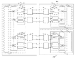
- FIG. 1 is a schematic configuration diagram of a system including an in-vehicle control device to which the present invention is applied;
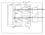
- FIG. 2 is an internal configuration diagram of the in-vehicle control device of Embodiment 1.
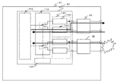
- FIG. 2 is an internal configuration diagram of the in-vehicle control device of Embodiment 1.
- FIG. 2 is an internal configuration diagram of the in-vehicle control device of Embodiment 1.
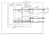
- FIG. 2 is an internal configuration diagram of the in-vehicle control device of Embodiment 1.
- FIG. 2 is an internal configuration diagram of the in-vehicle control device of Embodiment 1.
- FIG. 11 is an internal configuration diagram of an in-vehicle control device of Embodiment 2;
- FIG. 11 is an internal configuration diagram of an in-vehicle control device of Embodiment 2;
- FIG. 11 is an explanatory diagram of a database of Example 3;
- FIG. 11 is an explanatory diagram of a database of Example 3;
- FIG. 11 is a diagram of a comparative example for explaining Example 4;
- FIG. 11 is an explanatory diagram of Example 4;
- FIG. 11 is an explanatory diagram of Example 4;
- 10 is an operation time chart in Example 5.
- FIG. 10 is an operation flowchart in Example 6.
- FIG. FIG. 11 is a block diagram in Example 6; 10 is an operation flowchart in Example 7.
- An in-vehicle control device is applied, as an example, to a vehicle control system including an in-vehicle control device 10 and an actuator control device 20 shown in FIG.
- the microcomputer 30 of the vehicle-mounted control device 10 calculates the control amount of the vehicle electric load (not shown) based on various information, command to the actuator controller 20 having
- the plurality of communication circuits 40 are connected to the communication bus 50 and transmit and receive control signals.
- Actuator control device 20 controls the vehicle electrical load described above and transmits control information to vehicle control device 10 via communication bus 50 .
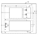
- FIG. 2 is an internal configuration diagram of the vehicle-mounted control device 10 according to Embodiment 1 of the present invention.
- the in-vehicle control device 10 is a so-called ECU (Electronic Control Unit), and includes a microcomputer (abbreviation for "microcontroller”) 30 and a communication circuit 40 .
- ECU Electronic Control Unit
- microcomputer abbreviation for "microcontroller”
- the communication circuit 40 is, for example, a communication circuit capable of CAN communication, which is commonly used in the in-vehicle control device 10 .
- the microcomputer 30 includes an arithmetic unit 100, a communication method switching unit 110, a communication module 120, and a failure diagnosis result unit 150.
- the communication method switching unit 110 operates the switching switches 110a and 110b to switch between two communication methods built in the communication module, which will be described later. switch.
- the communication module 120 includes a non-arbitration communication unit 130 and an arbitration communication unit 140.
- the non-arbitration communication unit 130 performs, for example, one-to-one transmission-only communication or reception-only communication, and only transmits and receives data.
- the communication baud rate can be arbitrarily set in the non-arbitration communication unit 130 .
- the arbitration communication unit 140 performs, for example, one-to-many, many-to-one, and many-to-many transmission/reception communication, and transmits/receives to/from the communication bus 50 arbitration data for determining communication timing synchronization and priority in addition to transmission/reception data. . Further, in the arbitration communication unit 140, since the communication baud rate performs arbitration processing, the communication baud rate defined by the conventional communication standard, for example, the CAN communication standard is set.
- the number of communication modules 40 is at least two, and the communication modules 40 are connected one by one to each of the plurality of communication circuits 40, and each of the plurality of communication modules 40 performs transmission-only communication or It has a non-arbitration communication unit 130 that performs reception-only communication in the non-arbitration method and performs control signal communication, and an arbitration communication unit 140 that performs control signal communication in the arbitration communication method.
- the calculation unit 100, the communication method switching unit 110, and the old book diagnosis result unit 150 constitute a communication control unit. It diagnoses whether or not a failure has occurred, and selects either control signal communication by the non-arbitration communication unit 130 or control signal communication by the arbitration communication unit 140 based on the result of the diagnosis.
- the communication method switching unit 110 selects the non-arbitration communication unit 130 for the two communication modules 120 based on the information of the new failure diagnosis result 150 . That is, both the switch 110a and the switch 110b are set to the non-arbitration communication unit 130 side.
- the arithmetic unit 100 of the microcomputer 30 performs communication with one of the two communication modules 120 as transmission-only communication and the other as reception-only communication.
- the two communication modules 120 operate exclusively for transmission processing and reception processing, respectively.
- communication via the non-arbitration communication unit 130 transmits/receives only transmission/reception data that does not include arbitration data to/from the communication bus 50, so more transmission data or reception is possible.
- Data can be transmitted and received on the communication bus 50, that is, transmission-dedicated processing of non-arbitration communication can be performed in a high communication bus load state, enabling faster communication.
- the calculation unit 100 outputs a control signal from the communication circuit 40. Diagnose whether or not a failure that prevents transmission and reception has occurred, detect the failure state, and store information indicating a communication bus failure in the failure diagnosis result unit 150 .
- Communication method switching unit 110 selects arbitration communication unit 140 for two communication modules 120 based on information from new failure diagnosis result unit 150 .
- the arithmetic unit 100 of the microcomputer 30 performs transmission/reception processing using only the communication module connected to the communication bus 50 that is not malfunctioning among the two communication modules 120 from the state of the communication method switching unit 110 . That is, in the state shown in FIG. 3, the changeover switch 110a on the side of the communication module 40 connected to the normal communication bus 50 is switched from the state shown in FIG. In the state shown in FIG. 4, the changeover switch 110b on the side of the communication module 40 connected to the communication bus 50 that has not failed is switched from the state shown in FIG.
- Communication via the arbitration communication unit 140 includes arbitration data other than transmission/reception data compared to communication via the non-arbitration communication unit 130, so high-speed communication cannot be performed. In other words, while ensuring high reliability between the vehicle-mounted control device 10 and the actuator control device 20, the control signal transmission/reception processing operation can be performed and continued.
- the in-vehicle control device 10 and other control devices whose operation is controlled by the in-vehicle control device 10 are connected via a communication bus 50, and the vehicle harness can be narrowed down to the communication bus 50, thereby suppressing an increase in the weight of the vehicle harness. be able to. Furthermore, if a failure occurs in the communication bus 50, the non-failed communication bus is used for arbitration communication. can ensure the reliability of being in a safe state.
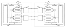
- FIG. 5 is a diagram illustrating a system in which two in-vehicle control devices are connected according to the first embodiment.
- the operation when a failure occurs in the communication bus 50 is the same as the examples shown in FIGS.
- the vehicle-mounted control device 10 is connected to the communication circuit 40 of the actuator control device 20 as the vehicle-mounted control device via the communication circuit 40 of the vehicle-mounted control device 10 .
- Non-arbitration transmission data transmitted from the in-vehicle control device 10 to the actuator control device 20 is received via the non-arbitration communication unit 130 of the actuator control device 20, and arbitration transmission data is transmitted to the actuator control device 20. is received via the arbitration communication unit 140 of the Transmission data transmitted from the actuator control device 20 to the in-vehicle control device 10 is also received via the non-arbitration communication section 130 or the arbitration communication section 140 of the in-vehicle control device 10 in the same manner as described above.
- Fig. 6 compares with Fig. 5 as an in-vehicle control device. It is a figure explaining the system by which two actuator control apparatuses 20A and 20B were connected.
- the in-vehicle control device 10 is provided with two communication modules 120 for transmitting and receiving data to and from the actuator control devices 20A and 20B. Transmission and reception of transmission data and reception data are performed via the non-arbitration communication unit 130 or the arbitration communication unit 140 of each control device as described above.
- the communication bus 50 is in a failure state, the other communication bus 50 that is not in failure is used, and by using the arbitration communication method of the communication module 120, transmission and reception can be performed between the in-vehicle control device and the actuator control device. can continue.
- Example 2 Next, a second embodiment of the in-vehicle control device according to the present invention will be described.
- the in-vehicle control device 10 according to the second embodiment differs from the above-described first embodiment in that it considers the influence of delay in switching from the non-arbitration communication method during normal operation to the arbitration communication method during failure.
- the configurations of the first and second embodiments are the same.
- the second embodiment is an example in which the communication method can be switched in a timely manner when a failure occurs by performing initial settings for each communication module setting unit (described later) before starting communication.
- the non-arbitration communication unit 130 of the communication module 120 Before the arithmetic unit 100 included in the communication control unit starts communication of control signals by the non-arbitration communication unit 130 and the arbitration communication unit 140 of the communication module 120, the non-arbitration communication unit 130 of the communication module 120 The setting of the communication function and the setting of the arbitration communication function of the arbitration communication unit 140 are performed in advance.
- FIG. 7 is an internal configuration diagram of the in-vehicle control device 10 according to Embodiment 2 of the present invention.
- the vehicle-mounted control device 10 of the second embodiment further includes a power switch monitor section 250 that monitors the activation signal of the vehicle-mounted control device 10 .
- the vehicle battery 200 is connected to the in-vehicle control device 10 via the power switch 210 , and power from the vehicle battery 200 is input to the power supply circuit 220 and the power switch monitor section 250 .
- the power switch monitor unit 250 outputs the monitor result of the detected power switch 21 to the microcomputer 30 .
- the microcomputer 30 checks the value output from the power switch monitor section 250 and determines the state of the power switch 210 .
- the power supply circuit 220 generates a power supply voltage used inside the in-vehicle control device 10 and supplies the power supply voltage to the microcomputer 30, for example.
- Various functional modules are generally built into the microcomputer 30, and information for operating the functional modules must be set in advance before each functional module is operated.
- the communication module 120 included in the second embodiment for example, it is necessary to start communication after setting the communication baud rate, transmission-only, reception-only, and the like.
- the arithmetic unit 100 of the microcomputer 30 checks the output value of the power switch monitor unit 250, and the control device 10 has been activated. After that, before starting communication, the calculation unit 100 supplies information necessary for the operation of the communication module 120 to the communication module setting unit A 230 and the communication module setting unit B 240 provided in each of the two communication modules 120. set. That is, immediately after the in-vehicle control device 10 is activated, information (functions) necessary for the operation of the communication module 120 is set in the communication module setting section A230 and the communication module setting section B240.
- the communication bus is set after the communication is started and before the setting is started. 50, or if a failure occurs in the communication bus 50 during the period set above, the arbitration communication method in which the arbitration communication unit 140 operates is switched to. In this case, there arises a problem that communication processing cannot be performed while the communication module setting section B240 is being set.
- the communication module setting units A230 and B240 are initialized in advance before starting communication. 50, there is no need to set the communication module setting section B240 of the arbitration communication section 140 of the communication module 120, and the time during which communication processing cannot be performed can be shortened. As a result, it becomes possible to switch the communication method in a timely manner.
- Example 3 a third embodiment of the vehicle-mounted control device will be described with reference to FIGS. 8A and 8B.
- the vehicle-mounted control device 10 of the third embodiment differs from the above-described first embodiment in that it considers the influence of delay in switching from the non-arbitration communication method during normal operation to the arbitration communication method during failure. Other points and configurations are the same as those of the first embodiment.
- the third embodiment by predetermining the priority of transmission/reception processing in each communication method before starting communication, communication methods can be switched in a timely manner when a failure occurs.
- the effect of the third embodiment is the same as the effect of the second embodiment.
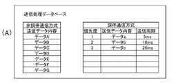
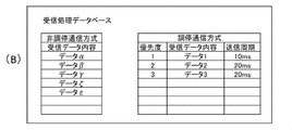
- FIGS. 8A and 8B show a database that determines the priority of transmission/reception processing of the microcomputer 30 in the third embodiment.
- the calculation unit 100 included in the communication control unit has a database in which the priority of transmission/reception processing of data transmitted/received by the arbitration communication unit 140 is set. Then, the arbitration communication unit 140 performs transmission/reception processing of the control signal, which is data, according to the priority set in the database.
- FIG. 8A shows the non-arbitration communication method and the arbitration communication method of the transmission processing database
- FIG. 8B shows the non-arbitration communication method and the arbitration communication method of the reception processing database.
- the priority of transmission data in the arbitration communication method is set. Priority is determined in order of data a, data b, and data c, and the transmission cycle is 5 ms for data a, 10 ms for data b, and 20 ms for data c.
- the priority of received data in the arbitration communication method is set. Priority is determined in order of data 1, data 2, and data 3, and the reception cycle is 10 ms for data 1, 20 ms for data 2, and 20 ms for data 3.
- FIG. 8B the priority of received data in the arbitration communication method is set. Priority is determined in order of data 1, data 2, and data 3, and the reception cycle is 10 ms for data 1, 20 ms for data 2, and 20 ms for data 3.
- the arbitration communication method needs to determine the priority of transmission/reception data in advance.
- the arbitration communication unit 140 does not need to calculate the priority each time a failure occurs in the communication bus 50, and can perform data processing according to the predetermined priority.
- the priority of transmission/reception data by the arbitration communication method is determined in advance before communication is started.
- the communication bus 50 there is no need to set the priority in communication processing via the arbitration communication unit 240 of the communication module 120, and the time during which communication processing cannot be performed can be shortened. .
- Example 4 an in-vehicle control device according to a fourth embodiment will be described with reference to FIGS. 9, 10 and 11.
- FIG. 9 An in-vehicle control device according to a fourth embodiment will be described with reference to FIGS. 9, 10 and 11.
- the in-vehicle control device differs from the above-described first embodiment in that shortening of the detection time of the failure state of the communication bus 50 is further taken into consideration.
- Other configurations of the fourth embodiment are similar to those of the first embodiment.
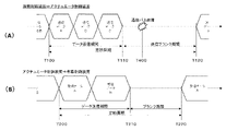
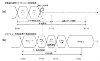
- FIG. 9 is a diagram of a comparative example for explaining the fourth embodiment, and is a time chart for explaining the operation of the in-vehicle control device 10 according to the first embodiment described above.
- FIG. 9 shows a time chart ((A) in FIG. 9) of transmission from the in-vehicle control device 10 to the actuator control device 20 by the non-arbitration communication unit 130, and a time chart of reception from the actuator control device 20 to the in-vehicle control device 10 ( FIG. 9B) shows the period of each transmission/reception data from time T100 to time T220.
- a period from time T110 to time T120 is a transmission blank period in which transmission processing is not performed.
- FIG. 10 is a time chart for explaining the operation of the in-vehicle control device 10 according to the fourth embodiment.
- the data transmission processing of the in-vehicle control device 10 and the actuator control device 20 between time T100 and time T110 shown in (A) of FIG. 10 and between time T200 and time T210 shown in (B) of FIG. is the same as the description of The fourth embodiment differs from the first embodiment in that a diagnostic data transmission period is provided between time T110 and time T120 for the purpose of early detection of a communication bus failure.
- the diagnostic data transmission period is from time T110 to time T120, and the in-vehicle control unit 10 detects that normal transmission is not possible, and the communication bus 50 is in a failure state.
- the actuator control device 20 detects that the diagnostic data to be received between time T110 and time T120 cannot be normally received, and recognizes that the communication bus 50 is in a failure state.
- the in-vehicle control device 10 and the actuator control device 20 detect the failure of the communication bus 50 at the timing T400 earlier than the end time T120 of the diagnostic data transmission period, and the actuator control device 20 to the in-vehicle control device 10 It is possible to switch the transmission-only communication of the non-arbitration communication method to the transmission/reception communication of the arbitration communication method.
- FIG. 11 is an internal block diagram of the communication circuit 40 of the in-vehicle control device 10.
- FIG. 11 when the communication bus 50 is in a normal state, when the microcomputer 30 transmits data from the TX circuit 41 of the communication circuit 40, the transmission data is input to the microcomputer 30 via the RX circuit 42 of the communication circuit 40. .
- the microcomputer 30 can confirm the state of the communication bus 50 by confirming the data transmitted from the TX circuit 41 of the communication circuit 40 and the transmission data received by the RX circuit 42 of the communication circuit 40 .
- the contents of the operation of the communication circuit 40 of the on-vehicle control device 10 are the same as those of the communication circuit 40 of the actuator control device 20, and the actuator control device 20 can perform the same fault diagnosis.
- a diagnostic data transmission period is set for the communication of the control signal of the non-arbitration communication unit 130, and the communication control unit determines whether or not a failure that prevents transmission and reception of the control signal has occurred during the diagnostic data transmission period. Then, based on the result of the diagnosis, the communication of the control signal by the non-arbitration communication unit 130 is switched to the communication of the control signal by the arbitration communication unit 140 .
- the same effects as those of the first embodiment can be obtained, and in addition, by performing transmission/reception data diagnosis communication during the transmission blank period, the detection time of the failure state of the communication bus 50 can be shortened. becomes possible.
- the fourth embodiment can also be applied to the first to third embodiments.
- the in-vehicle control device 10 of the fifth embodiment detects a failure on the communication bus 50 during transmission of communication data, and switches the communication method among a plurality of control devices.
- Other configurations of the fifth embodiment are the same as those of the fourth embodiment.
- the calculation unit 100 included in the communication control unit has a failure detection function of detecting a defect in the control signal received by the non-arbitration communication unit 130, and the calculation unit 100 included in the communication control unit When the non-arbitration communication unit 130 detects that the control signal received by the non-arbitration communication unit 130 is defective, the control signal communication by the non-arbitration communication unit 130 is switched to the control signal communication by the arbitration communication unit 140 .
- FIG. 12 is a time chart for explaining the operation of the vehicle-mounted control device 10 of the fifth embodiment.
- FIG. 12 shows a time chart ((A) in FIG. 12) for transmission from the vehicle-mounted control device 10 to the actuator control device 20 and a time chart ((B) in FIG. 12) for reception from the actuator control device 20 to the vehicle-mounted control device 10. , and from time T100 to time T220 each indicates the period of each transmission/reception data.
- FIG. 12 shows an example in which reception data cannot be received due to a failure of the communication bus 50.
- the communication method can also be applied to a failure of the communication IC of the non-arbitration communication unit 130 other than the communication bus 50, for example. is switched from the non-arbitration method to the arbitration method, and communication can be resumed using the arbitration communication method.
- Example 6 Next, the in-vehicle control device 10 of Example 6 will be described with reference to FIG. 13 .
- the sixth embodiment is characterized by confirming that arbitration communication can be performed immediately after the vehicle-mounted control device 10 is powered on.
- the rest of the configuration of the sixth embodiment is the same as that of the first embodiment, so illustration is omitted.
- step S100 the arithmetic unit 100 of the microcomputer 30 executes various initialization processes.
- step S110 the communication method switching unit 110 is set to the arbitration communication method executed by the arbitration communication unit 140, transmission/reception processing is performed, and initial communication diagnosis processing is performed.
- transmission data is transmitted from the in-vehicle control device 10 to the actuator control device 20 using the arbitration communication method.
- transmission data of the arbitration method is transmitted from the actuator control device 20 to the in-vehicle control device 10 .
- step S120 it is determined whether or not the above-described arbitration communication has been properly performed between the two control devices 10 and 20, that is, whether or not the control signal transmission/reception process of the arbitration communication unit 140 is normal. If the arbitration communication unit 140 determines that the arbitration communication is normal and the arbitration communication is properly performed, the process proceeds to step S130, the communication method of the vehicle-mounted control device 10 is changed from the arbitration method to the non-arbitration method, and the process immediately after the power is turned on. is completed, the communication of the control signal by the non-arbitration communication unit 130 is started.
- step S120 If it is determined in step S120 that the arbitration communication unit 140 is not normal and the arbitration communication is not properly performed, the process proceeds to step S140.
- step S140 a failure flag is set to indicate that the arbitration communication process could not be performed correctly.
- the microcomputer 30 of the in-vehicle control device 10 causes the display device (display section) 70 to display that the arbitration communication process was not properly performed, as shown in FIG. This allows the user to recognize that the arbitration communication process could not be performed correctly, and to recognize in advance that communication by the arbitration communication method cannot be performed when communication by the non-arbitration communication method fails. can do.
- step S140 the process proceeds to step S130.
- the same effects as those of the first embodiment can be obtained. Therefore, it is possible to avoid a situation in which communication is disabled by the non-arbitration communication method and the arbitration communication method.
- Example 7 an in-vehicle control device 10 according to a seventh embodiment will be described with reference to FIG.
- the circuit configuration and the like of the in-vehicle control device 10 are the same as those of the first embodiment, so illustration thereof is omitted.
- the seventh embodiment it is characterized in that in a communication circuit in which non-arbitration communication cannot be performed, whether or not transmission/reception processing can be resumed is periodically checked, and if it can be resumed, non-arbitration communication is resumed. .
- the communication control unit including the arithmetic unit 100 diagnoses whether or not there is a failure that prevents transmission and reception of control signals. 140, and after a certain period of time has elapsed, it is determined whether or not communication by the non-arbitration communication unit 130 is possible. resume.
- the flowchart shown in FIG. 15 is a routine task process that is executed at regular time intervals in the calculation unit 100 included in the communication control unit after the initialization process after the power supply of the vehicle-mounted control device 10 in the seventh embodiment is started. is shown.
- step S200 regular control processing relating to various controls such as setting a failure flag for the communication bus 50 that has failed is executed, and then the process proceeds to step S210.
- step S210 it is checked whether or not a communication bus failure flag that does not allow communication by the non-arbitration communication method is set. If the communication bus failure flag is not set, the process proceeds to step S220 to perform communication bus failure diagnosis.
- step S220 for example, it is diagnosed that communication data cannot be transmitted and received, and the process proceeds to step S230.
- step S230 it is determined (diagnosed) whether or not a communication bus failure has occurred. If no communication bus failure has occurred, the scheduled task processing is completed. In step S230, if a communication bus failure has occurred, the process proceeds to step S240.
- step S240 the transmission/reception processing of the communication network connected to the communication network in which the communication bus failure has occurred is stopped, and the process proceeds to step S250.
- step S250 the communication mode of the communication network in which no communication bus failure has occurred is switched from non-arbitration communication to arbitration communication, and the process proceeds to step S260.
- step S260 a communication mode switching state record is set (a communication bus failure flag is set) indicating that the communication mode of the communication network in which no communication bus failure has occurred is switched, and the process proceeds to step S270.
- step S270 the communication of the communication circuit network in which no communication bus failure has occurred is resumed. After that, the regular control process is carried out regularly.
- step S210 After a certain period of time has passed, if it is determined in step S210 that the communication bus failure flag is set, the process proceeds to step S280.
- step S280 a process is performed to confirm whether the transmission process of the communication network connected to the communication network in which the communication bus failure has occurred is possible, and the process proceeds to step S290.
- step S290 a process is performed to confirm whether the reception process of the communication network connected to the communication network in which the communication bus failure has occurred is possible, and the process proceeds to step S300.
- step S300 it is confirmed whether or not the transmission process and reception process have been performed correctly in steps S280 and S290. If the transmission/reception processing has been successfully performed, the process proceeds to step S310, and the transmission/reception processing by the non-arbitration communication method in the regular task is restarted. In step S300, if the transmission/reception process could not be performed correctly, the process of the regular task shown in FIG. 15 is completed. After that, the regular control process is carried out regularly.
- a transmission/reception check is performed to determine whether communication can be resumed, and if transmission/reception is possible, transmission/reception is resumed.
- a communication circuit network that uses the arbitration communication method fails, it is possible to communicate with other control devices using the non-arbitration method.
Landscapes
- Engineering & Computer Science (AREA)
- Mechanical Engineering (AREA)
- Computer Networks & Wireless Communication (AREA)
- Signal Processing (AREA)
- Small-Scale Networks (AREA)
Abstract
車両ハーネス重量増加を抑制できるとともに、車載通信システムの一部に通信障害が発生しても、車載通信システムの信頼性向上が可能な車載制御装置を提供する。車載制御装置(10)は通信バスに接続され、制御信号を送受信する複数の通信回路(40)と、2つの通信モジュール(120)であり、複数の通信回路(40)のそれぞれに一つずつ接続され非調停通信方式の送信専用通信又は非調停方式の受信専用通信を行い制御信号の通信を行う非調停通信部(130)と調停通信方式の制御信号の通信を行う調停通信部(140)とを有する。車載制御装置(10)は複数の通信回路(40)による制御信号の送受信が行えない故障が発生しているか否かを診断し、その結果に基づき、非調停通信部(130)による制御信号の通信と調停通信部(140)による制御信号の通信とのいずれかを選択する通信制御部とを備える。
Description
本発明は、車両に搭載される車載制御装置に関する。
車両に搭載される車載制御装置の搭載数量が多くなり、車載制御装置本体や車載制御装置を接続する車両ハーネス重量の増加が燃費改善の妨げの一部になっていることが知られている。
車両ハーネス重量を削減するために、車載制御装置と車載電気負荷間の車両ハーネス重量を削減するために、車載制御装置を車載電気負荷の近傍に配置、もしくは、車載電気負荷と一体化したアクチュエータ制御装置が知られている。
また、車両に搭載される複数の車載制御装置を統合した、さらに、アクチュエータ制御装置の一部機能を統合した車載制御装置が知られている。
統合車載制御装置では外部入力情報に基づき、車両電気負荷の作動量を演算し、アクチュエータ制御装置には通信線で作動量を指示し、または、アクチュエータ制御装置からの情報を受信する構成とする。これにより、統合車載制御装置やアクチュエータ制御装置間を接続する車両ハーネスを電源線や通信線に絞ることができ、車両ハーネス量を低減することができる。
統合車載制御装置とアクチュエータ制御装置間の通信量が増加した場合、通信線のみ増設することで車両ハーネス重量の増加を必要最低限に抑制することができる。
一方で、統合車載制御装置とアクチュエータ制御装置間は通信線のみで接続されるため、通信線に障害が発生した場合でも、車両システムが安全な状態となる信頼性を確保する技術が必要であり、その技術として、特許文献1に記載されたものがある。
特許文献1には、車載システムの一部に通信障害が発生した場合、システムの信頼性を向上させることができる車載通信システムの提供を目的とする技術が記載されている。
しかしながら、上記特許文献1に記載された技術にあっては、車両システムの一部通信バスに通信障害が発生した場合、通信障害が発生していない別通信バスに切り替えて通信することに限定しており、通信障害が発生した場合においても、高信頼性を確保するという点が十分に考慮されていない。つまり、特許文献1に記載の技術は、車載制御装置間における通信線の増設に対する車両ハーネス重量を抑制しながら、通信障害時における通信データの高信頼性を確保するというこの検討がされていないという課題があった。
本発明の目的は、このような技術課題を解決するためになされたものであって、車両ハーネス重量増加を抑制できるとともに、車載通信システムの一部に通信障害が発生しても、車載通信システムの信頼性向上が可能な車載制御装置を提供することである。
本発明の目的は、このような技術課題を解決するためになされたものであって、車両ハーネス重量増加を抑制できるとともに、車載通信システムの一部に通信障害が発生しても、車載通信システムの信頼性向上が可能な車載制御装置を提供することである。
上記目的を達成するため、本発明は、次のように構成される。
車載制御装置において、通信バスに接続され、制御信号を送受信する複数の通信回路と、少なくとも2つの通信モジュールであって、前記通信モジュールは、前記複数の通信回路のそれぞれに、一つずつ接続され、前記複数の通信モジュールのそれぞれは、非調停通信方式の送信専用通信又は非調停方式の受信専用通信を行い、前記制御信号の通信を行う非調停通信部と、調停通信方式の前記制御信号の通信を行う調停通信部と、を有する前記少なくとも2つの通信モジュールと、前記複数の通信回路による前記制御信号の送受信が行えない故障が発生しているか否かを診断し、診断した結果に基づいて、前記非調停通信部による前記制御信号の通信と前記調停通信部による前記制御信号の通信とのいずれかを選択する通信制御部と、を備える。
本発明によれば、車両ハーネス重量増加を抑制できるとともに、車載通信システムの一部に通信障害が発生しても、車載通信システムの信頼性向上が可能な車載制御装置を提供することができる。
以下、図面を参照して本発明に係る車載制御装置の実施形態について説明する。図面の説明において同一の要素には同一符号を付し、重複説明は省略する。
本発明に係る車載制御装置は、一例として、図1に示す車載制御装置10と、アクチュエータ制御装置20と、を含む車両制御システムに適用される。図1に示す車両制御システムにおいて、車載制御装置10のマイコン30が種々の情報に基づき車両電気負荷(図示せず)の制御量を算出し、通信回路40及び通信バス50を介して、マイコン30を有するアクチュエータ制御装置20へ命令を送信する。
つまり、複数の通信回路40は、通信バス50に接続され、制御信号を送受信する。アクチュエータ制御装置20は上述した車両電気負荷を制御し、通信バス50を介して、車両制御装置10へ制御情報を送信する。
(実施例1)
図2は、本発明の実施例1による車載制御装置10の内部構成図である。
図2は、本発明の実施例1による車載制御装置10の内部構成図である。
図2において、車載制御装置10は、いわゆるECU(Electronic Control Unit)であって、マイコン(「マイクロコントローラ」の略称である)30と、通信回路40とを備えている。
通信回路40は、例えば車載制御装置10に一般的に普及しているCAN通信が行える通信回路である。
そして、通信回路40を介して他の制御装置と通信するために、マイコン30は、演算部100と、通信方式切替部110と、通信モジュール120と、故障診断結果部150と、を備える。
通信方式切替部110は、故障診断結果部150に保存されている通信バス50の故障状態に基づき、後述する通信モジュールに内蔵される2つの通信方式を切替スイッチ110a及び切替スイッチ110bを操作して切り替える。
通信モジュール120は、非調停通信部130と調停通信部140とを備えており、非調停通信部130は、例えば1対1で送信専用通信、または、受信専用通信を行い、送受信データのみを通信バス50(図1に示す)へ送受信する通信部である。また、非調停通信部130において、通信ボーレートは任意に設定することができる。
つまり、例えば、CAN通信規格で規定されている通信ボーレートと比較して、2倍や3倍の通信ボーレートを設定することが可能である。
調停通信部140は、例えば1対多、多対1、多対多で送受信通信を行い、送受信データ以外に通信タイミングの同期や優先度を決める調停データが通信バス50へ送受信する通信部である。また、調停通信部140において、通信ボーレートは調停処理を行うため、従来通信規格、例えばCAN通信規格で規定されている通信ボーレートが設定される。
通信モジュール40は、少なくとも2つであって、通信モジュール40は、複数の通信回路40のそれぞれに、一つずつ接続され、複数の通信モジュール40のそれぞれは、非調停通信方式の送信専用通信又は非調停方式の受信専用通信を行い、制御信号の通信を行う非調停通信部130と、調停通信方式の制御信号の通信を行う調停通信部140とを有する。
演算部100と、通信方式切替部110と、古書診断結果部150とは、通信制御部を構成し、通信制御部100、110、150は、複数の通信回路40による制御信号の送受信が行えない故障が発生しているか否かを診断し、診断した結果に基づいて、非調停通信部130による制御信号の通信と調停通信部140による制御信号の通信とのいずれかを選択する。
次に、図2を参照して、本実施例1の車載制御装置10による非調停通信方式の通信制御処理について説明する。
通信バス50に、例えば、断線などの故障が発生していない正常な場合、故障診断結果150に通信バス正常という情報が記憶される。故障新診断結果150の情報に基づき通信方式切替部110が2つの通信モジュール120に対して、非調停通信部130を選択する。つまり、切替スイッチ110a及び切替スイッチ110bを共に非調停通信部130側に設定する。
マイコン30の演算部100は、通信方式切替部110の状態から、2つの通信モジュール120の一方を送信専用通信とし、他方を受信専用通信として通信を行う。
つまり、通信制御部100、110、150により、非調停通信部130による制御信号の通信が選択されているときは、2つの通信モジュール120は、それぞれ送信処理専用と受信処理専用として動作する。
調停通信部140を介した通信と比較して、非調停通信部130を介した通信は、調停データを含まない送受信データのみを通信バス50へ送受信するので、より多くの送信データ、または、受信データを通信バス50上で送受信でき、つまり、非調停通信の送信専用処理を高通信バス負荷状態で行うことができ、より高速な通信ができる。
次に、図3及び図4を参照して、本実施例1の車載制御装置10による調停通信方式の通信制御処理について、詳細に説明する。
2つの通信回路40のそれぞれに接続された2つの通信バス50のどちらか一方が、例えば、断線などの故障が発生している故障状態の場合、演算部100は、通信回路40による制御信号の送受信が行えない故障が発生しているか否かを診断し、故障状態を検知し、故障診断結果部150に通信バス故障という情報を記憶させる。故障新診断結果部150の情報に基づき通信方式切替部110が、2つの通信モジュール120に対して、調停通信部140を選択する。
マイコン30の演算部100は、通信方式切替部110の状態から、2つの通信モジュール120のうち、故障していない通信バス50に接続される通信モジュールのみを使い、送受信処理を行う。つまり、図3に示した状態の場合は、故障していない通信バス50に接続される通信モジュール40側の切替スイッチ110aを図3に示した状態から、調停通信部140側に切り替える。図4に示した状態の場合は、故障していない通信バス50に接続される通信モジュール40側の切替スイッチ110bを図4に示した状態から、調停通信部140側に切り替える。
調停通信部140を介した通信は、非調停通信部130を介した通信と比較して、送受信データ以外の調停データが含まれるので、高速通信が行えないが、一方で、1つの通信バス50上で、つまり、車載制御装置10とアクチュエータ制御装置20との間で高信頼性を確保しながら制御信号の送受信処理動作を行い、それを継続することができる。
車載制御装置10と車載制御装置10により動作制御される他の制御装置とは、通信バス50を介して接続され、車両ハーネスを通信バス50に絞ることができ、車両ハーネスの重量増加を抑制することができる。さらに、通信バス50に故障が発生した場合には、故障していない通信バスを使用して、調停通信を行うように構成されているので、通信バス50に障害が発生した場合でも、車両システムが安全な状態となる信頼性を確保することができる。
次に、図5と図6を参照して複数の車載制御装置とアクチュエータ制御装置とが接続されたシステムについて説明する。
図5は、実施例1における車載制御装置を2つ接続したシステムを説明する図である。通信バス50に故障が発生した場合の動作は、図3、図4に示した例と同様である。
図5において、車載制御装置10は、車載制御装置10の通信回路40を介して、車載制御装置としてのアクチュエータ制御装置20の通信回路40へ接続される。
車載制御装置10からアクチュエータ制御装置20へ送信される非調停方式の送信データは、アクチュエータ制御装置20の非調停通信部130を介して受信され、また、調停方式の送信データは、アクチュエータ制御装置20の調停通信部140を介して受信される。アクチュエータ制御装置20から車載制御装置10へ送信される送信データも上述と同じように、車載制御装置10の非調停通信部130、または、調停通信部140を介して、受信される。
図6は、図5と比較して、車載制御装置として。2つのアクチュエータ制御装置20A、20Bが接続されたシステムを説明した図である。車載制御装置10には、2つの通信モジュール120が備えられ、アクチュエータ制御装置20A、20Bとデータ送受信が行われる。送信データと受信データの送受信は上述したように各制御装置の非調停通信部130、または、調停通信部140を介して、送受信される。
図5及び図6に示したシステムにおいても、図2~図4で説明した例と同様に、車両ハーネスの重量増加を抑制することができ、かつ、通信バス50に障害が発生した場合でも、車両システムが安全な状態となる信頼性を確保することができる。
以上から、通信バス50が正常状態であれば、CAN通信回路を用いて、通信モジュール120の非調停通信方式を使うことで、従来のCAN通信による通信以上のデータ量を送受信することが可能である。
加えて、通信バス50が故障状態であれば、故障していないもう一方の通信バス50を用いて、通信モジュール120の調停通信方式を使うことで、車載制御装置とアクチュエータ制御装置間で送受信を継続することができる。
その結果、従来のCAN通信規格以上の通信データ量を送受信するために通信バスを追加せずに、車両ハーネス重量増加を抑制できるとともに、車載通信システムの一部に通信障害が発生しても、車載通信システムの信頼性を確保することができる。
(実施例2)
次に、本発明による車載制御装置の実施例2について説明する。
次に、本発明による車載制御装置の実施例2について説明する。
本実施例2による車載制御装置10は、正常時の非調停通信方式から故障時の調停通信方式への切替遅延の影響を考慮する点において、上述した実施例1と異なっている。その他の点については、実施例1と実施例2とは同様な構成となっている。
具体的には、実施例2は、通信開始前に予め各通信モジュール設定部(後述する)の初期設定を実施することで、故障発生時にタイムリーに通信方式を切り替えることができる例である。
つまり、通信制御部に含まれる演算部100が、通信モジュール120の非調停通信部130及び調停通信部140による制御信号の通信を開始する前に、通信モジュール120の非調停通信部130の非調停通信の機能の設定と、調停通信部140の調停通信の機能の設定とを予め行う。
図7は、本発明の実施例2による車載制御装置10の内部構成図である。
図7に示すように、本実施例2の車載制御装置10は、車載制御装置10の起動信号をモニタする電源スイッチモニタ部250を更に備えている。
車両バッテリ200は、電源スイッチ210を介して車載制御装置10へ接続され、車両バッテリ200からの電力は、電源回路220と電源スイッチモニタ部250に入力される。電源スイッチモニタ部250は、検出したで電源スイッチ21のモニタ結果をマイコン30へ出力する。マイコン30は電源スイッチモニタ部250から出力される値を確認し、電源スイッチ210の状態を判断する。
例えば、電源スイッチモニタ部250の出力値がHighであれば、電源スイッチ210が通電状態と判断し、電源スイッチモニタ部250の出力値がLowであれば、電源スイッチ210が遮断状態と判断する。また、電源回路220は、車載制御装置10の内部で使われる電源電圧を生成し、例えば、マイコン30に電源電圧を供給する。
マイコン30には一般的に種々の機能モジュールが内蔵され、各機能モジュールを動作させる前に、機能モジュールを動作させる情報を予め設定する必要がある。本実施例2に含まれる通信モジュール120では、例えば、通信ボーレートや送信専用、受信専用などを設定したあとに、通信を開始する必要がある。
電源スイッチ210が通電状態となり、電源回路220からマイコン30へ電源電圧が供給され、マイコン30が起動された後、マイコン30の演算部100は電源スイッチモニタ部250の出力値を確認し、制御装置10が起動されたことを判断する。その後、演算部100は、通信開始前に、2つの通信モジュール120のそれぞれに備えられている通信モジュール設定部A230と通信モジュール設定部B240に対して、通信モジュール120の動作に必要となる情報を設定する。つまり、車載制御装置10が起動した直後に、通信モジュール設定部A230と通信モジュール設定部B240とに対して通信モジュール120の動作に必要となる情報(機能)を設定する。
これに対して、通信開始後に、通信モジュール設定部A230と通信モジュール設定部B240を、それぞれ使用を始める直前に設定を行うこととすると、通信開始後であって、上記設定の開始以前に通信バス50に故障が発生していた場合または上記設定の期間中に通信バス50に故障が発生した場合、調停通信部140が動作する調停通信方式へ切り替えることになる。この場合、通信モジュール設定部B240の設定を行っている期間は、通信処理が行えないという状態が発生するという問題が生じる。
上記問題に対して、上述したように、車載制御装置10が起動した直後に通信モジュール設定部A230と通信モジュール設定部B240とに通信モジュール120の動作に必要となる情報を設定することで、通信バス50に故障が発生した場合、通信モジュール設定部B240は既に通信ボーレート等が設定されているので、タイムリーに非調停通信方式から調停通信方式へ切り替えることができる。
本実施例2の車載制御装置10によれば、上述の実施例1と同様の作用効果を得られるほか、通信開始前に予め各通信モジュール設定部A230、B240に初期設定を行うので、通信バス50に故障が発生したときに、通信モジュール120の調停通信部140の通信モジュール設定部B240の設定を行う必要がなく、通信処理が行えない時間を短くすることができる。その結果、通信方式をタイムリーに切り替えることが可能となる。
(実施例3)
次に、図8A及び図8Bを参照して車載制御装置の実施例3について説明する。
次に、図8A及び図8Bを参照して車載制御装置の実施例3について説明する。
本実施例3の車載制御装置10は、正常時の非調停通信方式から故障時の調停通信方式への切替遅延の影響を考慮する点において、上述した実施例1と異なっている。その他の点及び構成は実施例1と同様となっている。
具体的には、実施例3においては、通信開始前に各通信方式における送受信処理の優先度を予め決めておくことで、故障発生時にタイムリーに通信方式を切り替えることができる。本実施例3による効果は実施例2による効果と同様である。
図8A及び図8Bは、実施例3におけるマイコン30の送受信処理の優先度を決めるデータベースを示している。通信制御部に含まれる演算部100は、調停通信部140が送受信するデータの送受信処理の優先度が設定されたデータベースを有している。そして、調停通信部140は、上記データベースに設定された優先度に従ってデータである制御信号の送受信処理を行う。
図8Aは、送信処理データベースの非調停通信方式と調停通信方式を示し、図8Bは、受信処理データベースの非調停通信方式と調停通信方式を示す。
図8Aには、調停通信方式における送信データの優先度が設定されている。データa、データb、データcの順に優先度が決められ、送信周期はデータaが5ms、データbが10ms、データcが20msとなっている。
また、図8Bには、調停通信方式における受信データの優先度が設定されている。データ1、データ2、データ3の順に優先度が決められ、受信周期はデータ1が10ms、データ2が20ms、データ3が20msとなっている。
非調停通信方式と比較して、調停通信方式は送受信データの優先度を予め決めておく必要があり、調停通信方式の送受信データの優先度を例えば、マイコン30に記憶しておく。調停通信部140は、通信バス50に故障が発生した場合に、その発生毎に、優先度を演算する必要が無く、予め決められた優先度に従ってデータ処理を行うことができる。
本実施例3の車載制御装置10によれば、上述の実施例1及び実施例2と同様の作用効果を得られるほか、通信開始前に予め調停通信方式による送受信データの優先度を決めておくことで、通信バス50に故障が発生したときに、通信モジュール120の調停通信部240を介した通信処理で優先度の設定を行う必要がなく、通信処理が行えない時間を短縮することができる。その結果、通信方式をタイムリーに切り替えることが可能となる。
(実施例4)
次に、図9、図10及び図11を参照して、実施例4による車載制御装置を説明する。
次に、図9、図10及び図11を参照して、実施例4による車載制御装置を説明する。
本実施例4による車載制御装置は、通信バス50の故障状態の検知時間短縮を更に考慮する点において、上述した実施例1と異なる。実施例4の他の構成は、実施例1と同様となっている。
図9は、実施例4の説明のための比較例の図であり、上述した実施例1による車載制御装置10の動作を説明するタイムチャート図である。
図9は、非調停通信部130による、車載制御装置10からアクチュエータ制御装置20へ送信するタイムチャート(図9の(A))と、アクチュエータ制御装置20から車載制御装置10へ受信するタイムチャート(図9の(B))を示し、時刻T100から時刻T220は、各送受信データの期間を示している。
図9の(A)に示した車載制装置10からアクチュエータ制御装置20への送信処理では、時刻T100から時刻T110の期間でアクチュエータ制御装置20に必要となる送信データA、B及びCを送信している。時刻T110から時刻T120の期間は送信処理が行われない送信ブランク期間である。
例えば、後述する図11で説明する一般的な通信バスの故障検知方法を用いて、時刻T110から時刻T120の間の時刻T400で発生した通信バス故障が発生した状態、つまり、車載制御装置10からアクチュエータ制御装置20への送信処理が正しく行えない状態になったとしても、車載制御装置10は送信処理を実施していない期間であり、時刻T110か時刻T120の間で発生した通信バス故障は、時刻T120以降でのみ検知することが可能となり、タイムリーに故障を検知することができない。
図10は、実施例4による車載制御装置10の動作を説明するタイムチャート図である。図10の(A)に示す時刻T100から時刻T110の間と、図10の(B)に示す時刻T200から時刻T210の間の車載制御装置10及びアクチュエータ制御装置20のデータ送信処理は、図9の説明と同じである。実施例4は、時刻T110から時刻T120の間に、通信バス故障を早期に発見することを目的とした診断用データ送信期間を設けることが実施例1と異なる。
図10において、時刻T400で通信バス故障が発生すると、時刻T110から時刻T120では診断用データ送信期間であり、車載制御装置10は正常送信できないことを検知し、通信バス50が故障状態であることを認識する。また、アクチュエータ制御装置20は時刻T110から時刻T120の間に受信するべき診断用データを正常受信できないことを検知し、通信バス50が故障状態であることを認識する。
つまり、車載制御装置10とアクチュエータ制御装置20は、診断用データ送信期間の終了時刻T120よりも早いタイミング時刻T400で通信バス50の故障を検知して、アクチュエータ制御装置20から車載制御装置10への非調停通信方式の送信専用通信を、調停通信方式の送受信通信へ切り替えることが可能となる。
図11は、車載制御装置10の通信回路40の内部ブロック図である。図11において、通信バス50が正常状態の場合、マイコン30が通信回路40のTX回路41からデータを送信すると、通信回路40のRX回路42を経由して、送信データがマイコン30へ入力される。
一方で、通信バス50上で故障が発生している場合、通信回路40のTX回路41から通信バス50を介してデータを送信しても、通信回路40のRX回路42からマイコン30に入力される送信データは、通信バス50の故障に依存した固定値が入力される。つまり、マイコン30は通信回路40のTX回路41から送信するデータと、通信回路40のRX回路42が受信する送信データを確認することで、通信バス50の状態を確認することが可能である。
上記の車載制御装置10の通信回路40の動作内容は、アクチュエータ制御装置20の通信回路40の動作と同じであり、アクチュエータ制御装置20でも同等の故障診断を行える。
つまり、非調停通信部130の制御信号の通信には、診断用データ送信期間が設定され、通信制御部は、診断用データ送信期間に、制御信号の送受信が行えない故障が発生しているか否かを診断し、診断した結果に基づいて、非調停通信部130による制御信号の通信から調停通信部140よる制御信号の通信に切り替える。
本実施例4によれば、実施例1と同様な効果を得ることができる他、送信ブランク期間中に送受信データ診断用通信を行うことで、通信バス50の故障状態の検知時間短縮を短縮することが可能となる。
なお、本実施例4は、実施例1~3にも適用可能である。
(実施例5)
次に、図12を参照して本発明の実施例5について説明する。
次に、図12を参照して本発明の実施例5について説明する。
本実施例5の車載制御装置10は、通信データの送信中の通信バス50上の故障を検知し、複数の制御装置間で通信方式切替を行うことを考慮する点において、上述した実施例4と異なる。実施例5のその他の構成は実施例4と同様となっている。
実施例5においては、通信制御部に含まれる演算部100は、非調停通信部130が受信した制御信号の不良を検知する故障検知機能を有し、通信制御部に含まれる演算部100は、非調停通信部130が受信した制御信号の不良を検知すると、非調停通信部130による制御信号の通信から調停通信部140による制御信号の通信に切り替える。
図12は、本実施例5の車載制御装置10の動作を説明するタイムチャート図である。
図12は、本実施例5の車載制御装置10の動作を説明するタイムチャート図である。
図12は車載制御装置10からアクチュエータ制御装置20へ送信するタイムチャート(図12の(A))と、アクチュエータ制御装置20から車載制御装置10へ受信するタイムチャート(図12の(B))を示し、時刻T100から時刻T220は、それぞれ各送受信データの期間を示している。
車載制装置10からアクチュエータ制御装置20への送信処理では、時刻T100から時刻T110の期間でアクチュエータ制御装置20に必要となる送信データを送信している。この期間中に、時刻T400のタイミングにおいて通信バス50上で故障が発生すると、車載制御装置10からの通信データ送信途中で通信が途絶えることとなる。通信データ送信途中で通信が途絶えると、例えば、通信データのCRCを用いた故障検知や、一定時間内に通信データ受信不可を用いた故障検知によって、アクチュエータ制御装置20で通信バス50の故障を検出し、時刻T400以降の受信データで故障通信を受信する。その後、時刻T210で通信方式を非調停方式から調停方式へ切り替える初期化処理を行い、アクチュエータ制御装置20と車載制御装置10との相互で調停通信方式による通信を再開する。
図12には、通信バス50の故障による受信データの受信不可の発生の例を示したが、通信バス50以外の例えば、非調停通信部130の通信ICの故障発生に対しても、通信方式を非調停方式から調停方式へ切り替える初期化処理を行い、調停通信方式で通信を再開することが可能である。
本実施例5によれば、実施例1と同様な効果を得ることができる他、通信データの送信中の通信バス50上の故障以外の、通信ICの故障でも同様に故障を検知し、複数の制御装置間で通信方式の切替を行うことができる。
(実施例6)
次に、図13を参照して実施例6の車載制御装置10を説明する。
次に、図13を参照して実施例6の車載制御装置10を説明する。
非調停通信方式による通信が行えない場合、別通信回路を用いて調停通信方式へ切り替えて通信を行うが、調停通信方式部140が故障している状態で、非調停通信部130が故障した場合、他の制御装置と通信することができなくなるという問題がある。
そこで、本実施例6では、車載制御装置10の電源起動直後に調停通信が行えることを確認することを特徴としている。なお、本実施例6のその他の構成は、実施例1と同様となるので、図示は省略する。
図13に示すフローチャートは、車載制御装置10の電源が起動された直後に実行される。まず、ステップS100では、マイコン30の演算部100は、種々の初期化処理を実行する。ステップS110では、通信方式切替部110を、調停通信部140が実行する調停通信方式へ設定し、送受信処理を行って、初期通信診断処理を実行する。
具体的には、車載制御装置10からアクチュエータ制御装置20へ調停通信方式の送信データを送信する。また、アクチュエータ制御装置20から車載制御装置10へ調停方式の送信データの送信を行う。
ステップS120では、上述した調停通信が2つの制御装置10及び20間で正しく行われたか否か、つまり、調停通信部140の制御信号の送受信処理が正常か否かを判断する。調停通信部140が正常であと判断し、調停通信が正しく行われていれば、ステップS130へ移行し、車載制御装置10の通信方式を調停方式から非調停方式へ変更し、電源起動直後の処理を完了して、非調停通信部130による制御信号の通信を開始する。
ステップS120において、調停通信部140が正常ではないと判断され、調停通信が正しく行われていなければ、ステップS140へ移行する。
ステップS140では、調停通信処理が正しく行えなかったことを示す故障フラグをセットする。故障フラグがセットされると、車載制御装置10のマイコン30は、図14に示すように、ディスプレイ装置(表示部)70に調停通信処理が正しく行えなかったことを表示させる。これにより、ユーザは、調停通信処理が正しく行えなかったことを認識することができ、非調停通信方式による通信が故障した場合には、調停通信方式による通信も行えない状態であることを予め認識することができる。ステップS140の処理を終了すると、処理はステップS130へ移行する。
本実施例6によれば、実施例1と同様な効果を得ることができる他、車載制御装置10の電源起動直後に、予め調停通信方式で通信できるか否かを確認することで、予期せずに、非調停通信方式と調停通信方式で通信できなくなるという状況を回避することが可能となる。
(実施例7)
次に、図15を参照して実施例7による車載制御装置10を説明する。車載制御装置10の回路構成等は、実施例1と同様となるので、図示は省略する。
次に、図15を参照して実施例7による車載制御装置10を説明する。車載制御装置10の回路構成等は、実施例1と同様となるので、図示は省略する。
非調停通信方式による通信が行えない場合、別通信回路において調停通信方式へ切り替えて通信を行い、非調停通信が行えない通信回路では制御装置同士の送受信処理が停止する。
そして、調停通信方式を行っている通信回路網で故障が発生した場合、非調停通信が行えない通信回路では制御装置同士の送受信処理が停止しているため、他の制御装置と通信することができなくなるという問題がある。
そこで、本実施例7では、非調停通信が行えなかった通信回路において、送受信処理が再開できるか否かを定時的にチェックして再開できる場合には、非調停通信を再開すること特徴としている。
つまり、演算部100を含む通信制御部は、制御信号の送受信が行えない故障が発生しているか否かを診断し、故障が発生している場合、非調停通信部130による通信から調停通信部140による通信に切り替え、一定時間経過後、非調停通信部130による通信が可能か否かを判断し、非調停通信部130による通信が可能と判断した場合は、非調停通信部130による通信を再開する。
図15に示すフローチャートは、実施例7における車載制御装置10の電源が起動後の初期化処理が完了した後に、通信制御部に含まれる演算部100において、一定時間毎に実行される定時タスク処理を示している。
まず、ステップS200では、故障している通信バス50に対して故障フラグをセットする等の種々の制御に関する定時制御処理が実行され、ステップS210へ移行する。ステップS210では非調停通信方式による通信が行えない通信バス故障フラグがセットされているか否かを確認する。通信バス故障フラグがセットされていない場合、ステップS220へ移行し、通信バス故障診断を実施する。
ステップS220では、例えば、通信データを送受信できないことを診断し、ステップS230へ移行する。
ステップS230では、通信バス故障が発生しているか否かを判断する(診断する)。通信バス故障が発生していない場合、定時タスク処理を完了する。ステップS230で、通信バス故障が発生している場合、ステップS240へ移行する。
ステップS240では、通信バス故障が発生している通信網に接続されている通信回路網の送受信処理を停止し、ステップS250へ移行する。
ステップS250では、通信バス故障が発生していない通信回路網の通信モードを非調停通信から調停通信へ切り替え、ステップS260へ移行する。
ステップS260では、通信バス故障が発生していない通信回路網の通信モードを切り替えたことを示す通信モード切替状態記録をセット(通信バス故障フラグをセット)し、ステップS270へ移行する。
ステップS270では、通信バス故障が発生していない通信回路網の通信を再開する。その後、定時制御処理は、定時的に行われる。
一定時間経過後、ステップS210の判断で、通信バス故障フラグがセットされていると判断された場合、ステップS280へ移行する。
ステップS280では、通信バス故障が発生している通信網に接続されている通信回路網の送信処理が可能か確認する処理を行い、ステップS290へ移行する。
ステップS290では、通信バス故障が発生している通信網に接続されている通信回路網の受信処理が可能か確認する処理を行い、ステップS300へ移行する。
ステップS300では、ステップS280とステップS290で送信処理と受信処理が正しくできたか否かを確認する。送受信処理が正しく行えた場合、ステップS310へ移行し、定時タスクにおける非調停通信方式での送受信処理を再開する。ステップS300において、送受信処理が正しく行えなかった場合、図15に示す定時タスクの処理を完了する。その後、定時制御処理は、定時的に行われる。
本実施例7によれば、実施例1と同様な効果を得ることができる他、非調停通信で故障が発生し、調停通信に移行し、通信を停止していた通信回路網での非調停通信が再開できるか否かの送受信チェックを行い、送受信可能な場合には、送受信を再開する。これにより、調停通信方式を行っている通信回路網で故障した場合、他の制御装置と非調停方式で通信することが可能となる。
以上、本発明の実施例について記述したが、本発明は上述の実施例に限定されるものではなく、特許請求の範囲に記載された本発明の意図を逸脱しない範囲で、種々の設計変更を行うことができるものである。
10・・・車載制御装置、20・・・アクチュエータ制御装置、30 ・・・マイコン、40・・・通信回路、41・・・TX回路、42・・・RX回路、50・・・通信バス、100・・・演算部、110・・・通信方式切替部、120・・・通信モジュール、130・・・非調停通信部、140・・・調停通信部、150・・・故障診断結果部、200・・・バッテリ、210・・・電源スイッチ、220・・・電源回路、230・・・通信モジュール設定部A、240・・・通信モジュール設定部B、250・・・電源スイッチモニタ部
Claims (12)
- 通信バスに接続され、制御信号を送受信する複数の通信回路と、
少なくとも2つの通信モジュールであって、少なくとも2つの前記通信モジュールは、前記複数の通信回路のそれぞれに、一つずつ接続され、少なくとも2つの前記通信モジュールのそれぞれは、非調停通信方式の送信専用通信又は非調停方式の受信専用通信を行い、前記制御信号の通信を行う非調停通信部と、調停通信方式の前記制御信号の通信を行う調停通信部と、を有する少なくとも2つの前記通信モジュールと、
前記複数の通信回路による前記制御信号の送受信が行えない故障が発生しているか否かを診断し、診断した結果に基づいて、前記非調停通信部による前記制御信号の通信と前記調停通信部による前記制御信号の通信とのいずれかを選択する通信制御部と、
を備えることを特徴とする車載制御装置。 - 請求項1に記載の車載制御装置において、
前記通信制御部により、前記非調停通信部による前記制御信号の通信が選択されているときは、少なくとも2つの前記通信モジュールは、それぞれ送信処理専用と受信処理専用として動作することを特徴とする車載制御装置。 - 請求項2に記載の車載制御装置において、
前記非調停通信部は、非調停通信の送信専用処理を高通信バス負荷状態で行うことを特徴とする車載制御装置。 - 請求項2に記載の車載制御装置において、
前記調停通信部は、前記制御信号の、送受信処理動作を行うことを特徴とする車載制御装置。 - 請求項4に記載の車載制御装置において、
前記通信制御部により、前記調停通信部による前記制御信号の通信が選択されているときは、前記通信制御部は、少なくとも2つの前記通信モジュールのうち、前記制御信号の送受信が行えない故障が発生している一方の前記通信モジュールの通信を停止し、他方の前記通信モジュールの通信を行うことを特徴とする車載制御装置。 - 請求項5に記載の車載制御装置において、
前記通信制御部は、少なくとも2つの前記通信モジュールの前記非調停通信部及び前記調停通信部よる制御信号の通信を開始する前に、前記非調停通信部の非調停通信の機能の設定と、前記調停通信部の調停通信の機能の設定とを予め行うことを特徴とする車載制御装置。 - 請求項5に記載の車載制御装置において、
前記通信制御部は、前記調停通信部が送受信するデータの優先度が設定されたデータベースを有し、前記調停通信部は、前記データベースに設定された前記優先度に従って前記制御信号の送受信処理を行うことを特徴とする車載制御装置。 - 請求項5に記載の車載制御装置において、
前記非調停通信部の前記制御信号の通信には、診断用データ送信期間が設定され、前記通信制御部は、前記診断用データ送信期間に、前記制御信号の送受信が行えない故障が発生しているか否かを診断し、診断した結果に基づいて、前記非調停通信部による前記制御信号の通信から前記調停通信部による前記制御信号の通信に切り替えることを特徴とする車載制御装置。 - 請求項5に記載の車載制御装置において、
前記通信制御部は、前記非調停通信部が受信した前記制御信号の不良を検知する故障検知機能を有し、前記通信制御部が、前記非調停通信部が受信した前記制御信号の不良を検知すると、前記非調停通信部による前記制御信号の通信から前記調停通信部による前記制御信号の通信に切り替えることを特徴とする車載制御装置。 - 請求項5に記載の車載制御装置において、
表示部をさらに備え、
前記通信制御部は、
前記非調停通信部及び前記調停通信部よる制御信号の通信を開始する前に、前記調停通信部の前記制御信号の送受信処理が正常か否かを判断し、調停通信部が正常であると判断すると、前記非調停通信部による前記制御信号の通信を開始し、
前記調停通信部が正常ではない判断すると、前記表示部に調停通信処理が正しく行えなかったことを表示させることを特徴とする車載制御装置。 - 請求項5に記載の車載制御装置において、
前記通信制御部は、
前記制御信号の送受信が行えない故障が発生しているか否かを診断し、故障が発生している場合、前記非調停通信部による通信から前記調停通信部による調停通信に切り替え、一定時間経過後、前記非調停通信部による通信が可能か否かを判断し、前記非調停通信部による通信が可能と判断した場合は、非調停通信部による通信を再開することを特徴とする車載制御装置。 - 請求項1に記載の車載制御装置において、
2つ以上の複数の前記車載制御装置により前記制御信号が送受信されることを特徴とする車載制御装置。
Priority Applications (1)
| Application Number | Priority Date | Filing Date | Title |
|---|---|---|---|
| JP2023508439A JP7522301B2 (ja) | 2021-03-23 | 2021-09-24 | 車載制御装置 |
Applications Claiming Priority (2)
| Application Number | Priority Date | Filing Date | Title |
|---|---|---|---|
| JP2021049034 | 2021-03-23 | ||
| JP2021-049034 | 2021-03-23 |
Publications (1)
| Publication Number | Publication Date |
|---|---|
| WO2022201596A1 true WO2022201596A1 (ja) | 2022-09-29 |
Family
ID=83395504
Family Applications (1)
| Application Number | Title | Priority Date | Filing Date |
|---|---|---|---|
| PCT/JP2021/035118 Ceased WO2022201596A1 (ja) | 2021-03-23 | 2021-09-24 | 車載制御装置 |
Country Status (2)
| Country | Link |
|---|---|
| JP (1) | JP7522301B2 (ja) |
| WO (1) | WO2022201596A1 (ja) |
Citations (6)
| Publication number | Priority date | Publication date | Assignee | Title |
|---|---|---|---|---|
| JPH04240997A (ja) * | 1991-01-25 | 1992-08-28 | Fuji Heavy Ind Ltd | 車載電子装置の制御方法 |
| JPH08317501A (ja) * | 1995-05-22 | 1996-11-29 | Nippondenso Co Ltd | 電気自動車用制御装置のフェイルセーフ装置 |
| JP2005309957A (ja) * | 2004-04-23 | 2005-11-04 | Denso Corp | マイクロコンピュータ、車載システム |
| JP2008005340A (ja) * | 2006-06-23 | 2008-01-10 | Nec Corp | 通信装置、回線診断方法、プログラム、記録媒体 |
| JP2013085384A (ja) * | 2011-10-11 | 2013-05-09 | Mitsubishi Electric Corp | 電動車両用制御装置およびその方法 |
| JP2018046509A (ja) * | 2016-09-16 | 2018-03-22 | カルソニックカンセイ株式会社 | ゲートウェイ装置 |
Family Cites Families (1)
| Publication number | Priority date | Publication date | Assignee | Title |
|---|---|---|---|---|
| JP2015149541A (ja) | 2014-02-05 | 2015-08-20 | 株式会社デンソー | 通信システム |
-
2021
- 2021-09-24 JP JP2023508439A patent/JP7522301B2/ja active Active
- 2021-09-24 WO PCT/JP2021/035118 patent/WO2022201596A1/ja not_active Ceased
Patent Citations (6)
| Publication number | Priority date | Publication date | Assignee | Title |
|---|---|---|---|---|
| JPH04240997A (ja) * | 1991-01-25 | 1992-08-28 | Fuji Heavy Ind Ltd | 車載電子装置の制御方法 |
| JPH08317501A (ja) * | 1995-05-22 | 1996-11-29 | Nippondenso Co Ltd | 電気自動車用制御装置のフェイルセーフ装置 |
| JP2005309957A (ja) * | 2004-04-23 | 2005-11-04 | Denso Corp | マイクロコンピュータ、車載システム |
| JP2008005340A (ja) * | 2006-06-23 | 2008-01-10 | Nec Corp | 通信装置、回線診断方法、プログラム、記録媒体 |
| JP2013085384A (ja) * | 2011-10-11 | 2013-05-09 | Mitsubishi Electric Corp | 電動車両用制御装置およびその方法 |
| JP2018046509A (ja) * | 2016-09-16 | 2018-03-22 | カルソニックカンセイ株式会社 | ゲートウェイ装置 |
Also Published As
| Publication number | Publication date |
|---|---|
| JP7522301B2 (ja) | 2024-07-24 |
| JPWO2022201596A1 (ja) | 2022-09-29 |
Similar Documents
| Publication | Publication Date | Title |
|---|---|---|
| JP5283651B2 (ja) | 車両用の制御装置 | |
| KR102533939B1 (ko) | 차량 제어 시스템 | |
| US10800449B2 (en) | Computer architecture and functional architecture for increasing the fail-safety of auxiliary power steering | |
| CN111971934B (zh) | 网关装置 | |
| US20200139982A1 (en) | Vehicle control device and vehicle control system | |
| US10497189B2 (en) | Vehicular control device and method of controlling vehicular control device | |
| CN114691225A (zh) | 用于车载冗余系统的切换方法、系统、车辆和存储介质 | |
| US9817741B2 (en) | Method for monitoring an apparatus connected to a communication channel | |
| US11897342B2 (en) | Electronic control apparatus | |
| JP2021013135A (ja) | 車両用電子制御装置 | |
| US8447447B2 (en) | Actuation system for a drive unit of a motor vehicle | |
| CN114633706A (zh) | 避免车辆非预期熄火下电的安全监控系统、方法及车辆 | |
| JP2010154594A (ja) | 電子制御システムの故障診断装置 | |
| EP1359057B1 (en) | Vehicle data transmission system with link redundancy | |
| JP7522301B2 (ja) | 車載制御装置 | |
| WO2011034052A1 (ja) | 車両用電子制御装置 | |
| CN114312833A (zh) | 基于功能安全的自动驾驶系统状态控制合理性的校验方法 | |
| JP2001322527A (ja) | 車両用乗員保護システム | |
| KR101039926B1 (ko) | 차량용 자기진단 제어 시스템 | |
| JPH04215140A (ja) | コンピュータ装置 | |
| US10899238B2 (en) | Control apparatus including a key hold function of supplying power to a controller and control method thereof | |
| JP5764043B2 (ja) | 車両の制御システム | |
| CN113119885A (zh) | 电动汽车的整车控制器异常检测方法及电动汽车 | |
| US20250296620A1 (en) | Vehicle control device | |
| JP2001344013A (ja) | 車両用装置の故障診断方法 |
Legal Events
| Date | Code | Title | Description |
|---|---|---|---|
| 121 | Ep: the epo has been informed by wipo that ep was designated in this application |
Ref document number: 21933195 Country of ref document: EP Kind code of ref document: A1 |
|
| ENP | Entry into the national phase |
Ref document number: 2023508439 Country of ref document: JP Kind code of ref document: A |
|
| NENP | Non-entry into the national phase |
Ref country code: DE |
|
| 122 | Ep: pct application non-entry in european phase |
Ref document number: 21933195 Country of ref document: EP Kind code of ref document: A1 |