WO2022201472A1 - バッテリ収容装置 - Google Patents
バッテリ収容装置 Download PDFInfo
- Publication number
- WO2022201472A1 WO2022201472A1 PCT/JP2021/012727 JP2021012727W WO2022201472A1 WO 2022201472 A1 WO2022201472 A1 WO 2022201472A1 JP 2021012727 W JP2021012727 W JP 2021012727W WO 2022201472 A1 WO2022201472 A1 WO 2022201472A1
- Authority
- WO
- WIPO (PCT)
- Prior art keywords
- opening
- battery
- connection terminal
- side connection
- unit
- Prior art date
- Legal status (The legal status is an assumption and is not a legal conclusion. Google has not performed a legal analysis and makes no representation as to the accuracy of the status listed.)
- Ceased
Links
Images




Classifications
-
- H—ELECTRICITY
- H01—ELECTRIC ELEMENTS
- H01M—PROCESSES OR MEANS, e.g. BATTERIES, FOR THE DIRECT CONVERSION OF CHEMICAL ENERGY INTO ELECTRICAL ENERGY
- H01M50/00—Constructional details or processes of manufacture of the non-active parts of electrochemical cells other than fuel cells, e.g. hybrid cells
- H01M50/20—Mountings; Secondary casings or frames; Racks, modules or packs; Suspension devices; Shock absorbers; Transport or carrying devices; Holders
- H01M50/296—Mountings; Secondary casings or frames; Racks, modules or packs; Suspension devices; Shock absorbers; Transport or carrying devices; Holders characterised by terminals of battery packs
-
- B—PERFORMING OPERATIONS; TRANSPORTING
- B60—VEHICLES IN GENERAL
- B60K—ARRANGEMENT OR MOUNTING OF PROPULSION UNITS OR OF TRANSMISSIONS IN VEHICLES; ARRANGEMENT OR MOUNTING OF PLURAL DIVERSE PRIME-MOVERS IN VEHICLES; AUXILIARY DRIVES FOR VEHICLES; INSTRUMENTATION OR DASHBOARDS FOR VEHICLES; ARRANGEMENTS IN CONNECTION WITH COOLING, AIR INTAKE, GAS EXHAUST OR FUEL SUPPLY OF PROPULSION UNITS IN VEHICLES
- B60K1/00—Arrangement or mounting of electrical propulsion units
- B60K1/04—Arrangement or mounting of electrical propulsion units of the electric storage means for propulsion
-
- H—ELECTRICITY
- H01—ELECTRIC ELEMENTS
- H01M—PROCESSES OR MEANS, e.g. BATTERIES, FOR THE DIRECT CONVERSION OF CHEMICAL ENERGY INTO ELECTRICAL ENERGY
- H01M50/00—Constructional details or processes of manufacture of the non-active parts of electrochemical cells other than fuel cells, e.g. hybrid cells
- H01M50/20—Mountings; Secondary casings or frames; Racks, modules or packs; Suspension devices; Shock absorbers; Transport or carrying devices; Holders
- H01M50/204—Racks, modules or packs for multiple batteries or multiple cells
- H01M50/207—Racks, modules or packs for multiple batteries or multiple cells characterised by their shape
- H01M50/209—Racks, modules or packs for multiple batteries or multiple cells characterised by their shape adapted for prismatic or rectangular cells
-
- H—ELECTRICITY
- H01—ELECTRIC ELEMENTS
- H01M—PROCESSES OR MEANS, e.g. BATTERIES, FOR THE DIRECT CONVERSION OF CHEMICAL ENERGY INTO ELECTRICAL ENERGY
- H01M50/00—Constructional details or processes of manufacture of the non-active parts of electrochemical cells other than fuel cells, e.g. hybrid cells
- H01M50/20—Mountings; Secondary casings or frames; Racks, modules or packs; Suspension devices; Shock absorbers; Transport or carrying devices; Holders
- H01M50/271—Lids or covers for the racks or secondary casings
-
- H—ELECTRICITY
- H01—ELECTRIC ELEMENTS
- H01M—PROCESSES OR MEANS, e.g. BATTERIES, FOR THE DIRECT CONVERSION OF CHEMICAL ENERGY INTO ELECTRICAL ENERGY
- H01M50/00—Constructional details or processes of manufacture of the non-active parts of electrochemical cells other than fuel cells, e.g. hybrid cells
- H01M50/50—Current conducting connections for cells or batteries
- H01M50/572—Means for preventing undesired use or discharge
- H01M50/574—Devices or arrangements for the interruption of current
-
- B—PERFORMING OPERATIONS; TRANSPORTING
- B60—VEHICLES IN GENERAL
- B60K—ARRANGEMENT OR MOUNTING OF PROPULSION UNITS OR OF TRANSMISSIONS IN VEHICLES; ARRANGEMENT OR MOUNTING OF PLURAL DIVERSE PRIME-MOVERS IN VEHICLES; AUXILIARY DRIVES FOR VEHICLES; INSTRUMENTATION OR DASHBOARDS FOR VEHICLES; ARRANGEMENTS IN CONNECTION WITH COOLING, AIR INTAKE, GAS EXHAUST OR FUEL SUPPLY OF PROPULSION UNITS IN VEHICLES
- B60K1/00—Arrangement or mounting of electrical propulsion units
- B60K1/04—Arrangement or mounting of electrical propulsion units of the electric storage means for propulsion
- B60K2001/0455—Removal or replacement of the energy storages
- B60K2001/0466—Removal or replacement of the energy storages from above
-
- B—PERFORMING OPERATIONS; TRANSPORTING
- B60—VEHICLES IN GENERAL
- B60Y—INDEXING SCHEME RELATING TO ASPECTS CROSS-CUTTING VEHICLE TECHNOLOGY
- B60Y2200/00—Type of vehicle
- B60Y2200/10—Road Vehicles
- B60Y2200/12—Motorcycles, Trikes; Quads; Scooters
-
- H—ELECTRICITY
- H01—ELECTRIC ELEMENTS
- H01M—PROCESSES OR MEANS, e.g. BATTERIES, FOR THE DIRECT CONVERSION OF CHEMICAL ENERGY INTO ELECTRICAL ENERGY
- H01M2220/00—Batteries for particular applications
- H01M2220/20—Batteries in motive systems, e.g. vehicle, ship, plane
-
- Y—GENERAL TAGGING OF NEW TECHNOLOGICAL DEVELOPMENTS; GENERAL TAGGING OF CROSS-SECTIONAL TECHNOLOGIES SPANNING OVER SEVERAL SECTIONS OF THE IPC; TECHNICAL SUBJECTS COVERED BY FORMER USPC CROSS-REFERENCE ART COLLECTIONS [XRACs] AND DIGESTS
- Y02—TECHNOLOGIES OR APPLICATIONS FOR MITIGATION OR ADAPTATION AGAINST CLIMATE CHANGE
- Y02E—REDUCTION OF GREENHOUSE GAS [GHG] EMISSIONS, RELATED TO ENERGY GENERATION, TRANSMISSION OR DISTRIBUTION
- Y02E60/00—Enabling technologies; Technologies with a potential or indirect contribution to GHG emissions mitigation
- Y02E60/10—Energy storage using batteries
Definitions
- the present invention relates to a battery housing device.
- Patent Literature 1 describes an electric motorcycle that is detachably mounted with a battery and driven by electric power stored in the battery.
- a motorcycle described in Patent Document 1 includes a battery housing device that detachably houses a battery.
- a battery accommodation device mounted on a motorcycle disclosed in Patent Document 1 includes a lock mechanism capable of fixing and holding a battery in a battery case, a case-side connection terminal that connects to a battery-side connection terminal provided on the battery, and an operation lever. and have.
- the battery storage device mounted on the motorcycle disclosed in Patent Document 1 switches the lock mechanism between the battery fixed state and the battery non-fixed state by operating the operation lever, and the battery side connection terminal to switch the connection terminal on the case side between the connected state and the disconnected state.
- the battery accommodation device of Patent Document 1 has an operation lever for displacing the case-side connection terminal, and there is a problem that the number of parts increases. Further, in the battery storage device of Patent Document 1, it is necessary to operate the operation lever to connect the case-side connection terminals to the battery-side terminals. is required to operate the operating lever in order to connect to the battery side terminal, and there is a problem that the number of man-hours for operation increases.
- the present invention provides a battery accommodation device that does not require a member such as a lever for displacing the case-side connection terminal, and that can reduce the number of man-hours for connecting the case-side connection terminal to the battery-side terminal.
- the present invention a body portion having a battery housing portion provided with an insertion/removal opening opening in a first direction; an opening/closing portion provided to be capable of opening/closing operation with respect to the main body portion so as to open/close the insertion/removal port; and a case-side connection terminal
- a battery having a battery-side connection terminal is accommodated in the battery accommodating portion so as to be insertable and removable from the insertion/removal opening
- the case-side connection terminal is provided so as to be displaceable between a connection position connected to the battery-side connection terminal and a retracted position separated from the battery-side connection terminal
- the battery accommodation device further includes a connection terminal displacement mechanism that displaces the case-side connection terminal between the connection position and the retracted position, The connection terminal displacing mechanism displaces the case-side connection terminal in conjunction with the opening/closing operation of the opening/closing portion.
- the case-side connection terminal can be displaced between the connection position and the retracted position in conjunction with the opening/closing operation of the opening/closing portion, the case-side connection terminal can be displaced between the connection position and the retracted position.
- a member such as a lever or a handle for displacing by is unnecessary.
- the number of parts of the battery accommodation device can be reduced.
- the case-side connection terminals are displaced and connected to the battery terminals by the opening/closing operation of the opening/closing part, there is no need to separately perform an operation for connecting the case-side connection terminals to the battery-side terminals. It is possible to reduce the man-hours required for connecting to the battery side terminal.
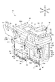
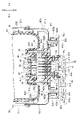
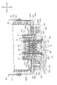
- FIG. 2 is a perspective view of the battery accommodation device of FIG. 1 as seen obliquely from the upper rear side with the main body cover and the top cover removed;
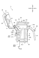
- FIG. 3 is a side view of the battery housing device of FIG. 2 as seen from the left side, showing the opening/closing unit at the fully open position;
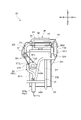
- FIG. 3 is a side view of the battery housing device of FIG. 2 as seen from the left side, showing the opening/closing unit at the fully closed position;
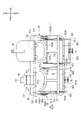
- FIG. 3 is a rear view of the battery accommodation device of FIG.
- FIG. 2 is a perspective view of an input plug of the battery housing device of FIG. 1;
- FIG. FIG. 2 is a side view seen from the left side, showing the positional relationship between an opening/closing unit and an input plug in the battery accommodation device of FIG. 1;
- FIG. 2 is a cross-sectional view of the essential parts of the battery accommodation device of FIG. 1 when the input plug is at the retracted position;
- FIG. 2 is a cross-sectional view of the main parts of the battery accommodation device of FIG. 1 when the input plug is at the insertion start position;
- FIG. 2 is a cross-sectional view of the main parts of the battery accommodation device of FIG. 1 when the input plug is in the connected position;
- FIG. 2 is a cross-sectional view of the essential parts of the battery accommodation device of FIG. 1 when the opening/closing unit is in the fully closed position;
- the battery accommodation device 10 accommodates a battery 80 in a detachable manner.
- the battery 80 has a substantially quadrangular prism shape elongated in the vertical direction.
- the front, rear, left, right, and top and bottom directions are defined such that the rotation axis direction of the opening/closing unit 30 is the left and right direction, the insertion/removal direction of the battery 80 is the top and bottom direction,
- the direction perpendicular to the rotation axis direction of the opening/closing unit 30 and the inserting/removing direction of the battery 80, that is, the rotating direction of the opening/closing unit 30 when viewed from above and below is the front-rear direction. Described as a standard.
- the front of the battery storage device 10 is indicated by Fr, the rear by Rr, the left by L, the right by R, the upper by U, and the lower by D.
- front, rear, up, down, left, and right directions defined in this specification are defined for convenience only, and are irrelevant to the front, rear, up, down, left, and right directions of the product in which the battery housing device 10 is mounted. Further, the front, rear, up, down, left, and right directions of the battery housing device 10 mounted on a product may be the same as or different from the above directions.
- the battery 80 has a substantially quadrangular prism shape elongated in the vertical direction.
- a grip portion 81 is provided on the upper surface 80U of the battery 80 .
- the grip portion 81 extends in the front-rear direction at substantially the center in the left-right direction of the upper surface 80U.
- a battery side connection terminal unit 90 is provided near the rear end of the bottom surface 80D of the battery 80.
- the battery-side connection terminal unit 90 is provided so as to be recessed upward from the bottom surface 80D of the battery 80 so that the lower end surface thereof is substantially flush with the bottom surface 80D of the battery 80 .
- a pair of positive and negative output terminal sockets 91 for outputting power stored in the battery 80 and a plurality of signal terminal sockets 92 for outputting various information signals indicating the state of the battery 80 are provided.
- the plurality of signal terminal sockets 92 are arranged in a row in the left-right direction.
- the pair of output terminal sockets 91 are provided on the left outer side and the right outer side of the plurality of signal terminal sockets 92 arranged in a line in the left-right direction, and are arranged in a line in the left-right direction together with the plurality of signal terminal sockets 92 .
- the battery side connection terminal unit 90 further includes a pair of left and right guide holes 93 recessed upward.
- a pair of left and right guide holes 93 are provided on the left outer side of the output terminal socket 91 arranged on the left side and on the right outer side of the output terminal socket 91 arranged on the right side.
- the battery accommodation device 10 includes a main body unit 20 , an opening/closing unit 30 , a case-side connection terminal unit 40 , a connection terminal displacement mechanism 50 and a buckle unit 60 .
- 3 is a diagram showing the opening/closing unit 30 at the fully open position
- FIG. 4 is a diagram showing the opening/closing unit 30 at the fully closed position.
- the main unit 20 has a substantially quadrangular prism shape such that (front-rear dimension) ⁇ (left-right dimension) ⁇ (vertical dimension).
- the main unit 20 has a front surface 20F, a rear surface 20B, a left surface 20L, a right surface 20R, an upper surface 20U, and a bottom surface 20D.
- the main body unit 20 includes a main body frame 21 that forms a skeleton of the main body unit 20, a main body cover 22 that forms the outer shell of the main body unit 20, and a battery housing case 23 that detachably houses the battery 80. have.
- the main unit 20 includes two battery storage cases 23 arranged in the left-right direction.
- the main body cover 22 comprises a front surface 20F, a rear surface 20B, a left surface 20L, a right surface 20R, and a bottom surface 20D of the main unit 20.
- a main cover 22M in the shape of a rectangular cylinder with a bottom and an upper cover constituting an upper surface 20U of the main unit 20 are provided. 22U and The upper cover 22U and the main cover 22M are locked, and at least one of the main cover 22M and the upper cover 22U is fixed to the body frame 21. As shown in FIG. Thereby, the body cover 22 is fixed to the body frame 21 .
- the upper cover 22U is provided with an insertion/removal portion 221 in the shape of a rectangular tube penetrating vertically when viewed from above.
- two insertion/removal portions 221 are provided side by side in the left-right direction.
- the insertion/removal portion 221 is formed to fit into an opening 231 of the battery housing case 23 to be described later, and communicates with the inside of the battery housing case 23 .
- the battery 80 housed in the battery housing case 23 is vertically inserted into and removed from the main unit 20 through the insertion/removal portion 221 .
- the battery storage case 23 has a bottomed rectangular tubular shape that is long in the vertical direction, and has a rectangular tubular side wall portion 23S and a bottom wall portion 23D.
- the battery storage case 23 is arranged below an insertion/removal portion 221 provided on the main body cover 22 of the main unit 20 , is fitted with the insertion/removal portion 221 , and is fixed to the main body frame 21 .
- the main unit 20 includes two battery storage cases 23 arranged below each insertion/removal portion 221 .
- the upper surface of the battery housing case 23 is an opening 231 that opens upward.
- an insertion hole 232 penetrating vertically is provided at a position facing the battery side connection terminal unit 90 when the battery 80 is housed in the battery housing case 23. (see FIGS. 8A-8D).
- the body unit 20 is surrounded by the side wall portion 23S and the bottom wall portion 23D of the battery housing case 23 and the insertion/removal portion 221 of the body cover 22 fitted to the battery housing case 23 in the vertical direction.
- a battery housing portion 24 having a substantially square cylindrical shape with a long bottom is formed.
- the battery accommodating portion 24 is provided with an insertion/removal opening 241 opened upward by a rectangular cylindrical insertion/removal portion 221 provided in the main body cover 22 and penetrating in the vertical direction.
- a battery 80 is housed in the battery housing portion 24 . Further, the battery 80 can be vertically moved to be inserted into and removed from the battery accommodating portion 24 through the insertion/removal port 241 .
- the main body unit 20 has two battery storage sections 24 arranged in the left-right direction.
- the batteries 80 housed in the two battery housing units 24 are connected in series by power lines (not shown) provided in the battery housing device 10 .
- An electrical component 70 is housed below the two battery housing cases 23 and inside the bottomed square cylindrical main cover 22M.
- the electrical component 70 includes a battery management system (BMS) that monitors the state of the battery 80 housed in the battery housing unit 24 and controls the output, and the battery 80 housed in the battery housing unit 24. It has a DCDC converter capable of stepping up and down the voltage of the output power, and a system power supply that is lower voltage and smaller than the battery 80 and drives the battery management system.
- BMS battery management system
- the opening/closing unit 30 is provided so as to be capable of opening/closing with respect to the main unit 20 so as to open/close the insertion/removal opening 241 .
- One opening/closing unit 30 is provided for each battery housing portion 24 of the main unit 20 .
- the body unit 20 is provided with two battery storage sections 24 aligned in the left-right direction, and therefore two opening/closing units 30 are also provided side-by-side in the left-right direction.
- Each opening/closing unit 30 includes a cover frame 31 forming a skeleton of the opening/closing unit 30, a hinge shaft 32, a pressing member 33 fixed to the cover frame 31, and a top cover 34 forming an outer shell of the opening/closing unit 30. , provided.
- the hinge shaft 32 extends in the left-right direction behind the battery housing portion 24 and in the vicinity of the insertion/removal opening 241 of the battery housing portion 24 .
- the hinge shaft 32 is integrally molded with the cover frame 31 .
- the hinge shaft 32 is supported by the body frame 21 of the body unit 20 .
- the opening/closing unit 30 is rotatable with respect to the main body unit 20 around a hinge shaft 32 that is pivotally supported by the main body frame 21 of the main body unit 20 and extends in the left-right direction.
- the opening/closing operation of the opening/closing unit 30 is performed by rotating the opening/closing unit 30 with respect to the main body unit 20 with the hinge shaft 32 as the rotation axis.
- the closing operation of the opening/closing unit 30 is performed by rotating the opening/closing unit 30 clockwise with respect to the main body unit 20 about the hinge shaft 32 as viewed from the front, that is, the left direction.
- the opening operation of the opening/closing unit 30 is performed by rotating the opening/closing unit 30 backward, that is, counterclockwise when viewed from the left with respect to the main body unit 20 with the hinge shaft 32 as the rotation axis.
- the pressing member 33 is made of an elastic member such as rubber.
- the pressing member 33 is provided to press the upper surface 80U of the battery 80 downward when the battery 80 is housed in the battery housing portion 24 and the opening/closing unit 30 is in the fully closed position.
- the battery 80 housed in the battery housing portion 24 is pressed downward by the pressing member 33, so that when the battery 80 is in operation, the battery 80 is placed in the battery housing portion. 24 can be suppressed, and failure of the battery 80 and poor connection between the battery-side connection terminal unit 90 and the case-side connection terminal unit 40 can be suppressed.
- the top cover 34 is formed to cover the cover frame 31 , the pressing member 33 , and the insertion/removal opening 241 of the battery housing portion 24 from above to seal the battery housing portion 24 when the opening/closing unit 30 is in the fully closed position. ing.
- the insertion/removal opening 241 of the battery containing portion 24 is covered with the top cover 34, so that the battery 80 contained in the battery containing portion 24 is removed from the battery containing portion 24.
- the case-side connection terminal unit 40 is housed inside the body unit 20 .
- the case-side connection terminal unit 40 holds an input plug 41 that can be inserted into the battery-side connection terminal unit 90 by passing through an insertion hole 232 provided in the bottom wall portion 23D of the battery housing case 23, and the input plug 41.
- the input plug 41 includes a terminal block 410 , a pair of positive and negative input terminal pins 411 , and the same number of signal terminal pins 412 as the signal terminal sockets 92 . Both the input terminal pin 411 and the signal terminal pin 412 are provided so as to protrude upward from the terminal block 410 .
- the plurality of signal terminal pins 412 are arranged in a row in the horizontal direction so that they can be fitted and connected to the signal terminal sockets 92 facing each other.
- the pair of input terminal pins 411 are provided on the left outer side and the right outer side of the plurality of signal terminal pins 412 arranged in a line in the left-right direction so that they can be fitted and connected to the output terminal sockets 91 facing each other. are arranged in a line in the left-right direction together with the signal terminal pins 412 of .
- a pair of left and right input terminal pins 411 are electrically connected to the aforementioned DCDC converter of the electrical component 70 housed in the main unit 20 .
- the pair of left and right input terminal pins 411 are fitted and connected to the pair of left and right output terminal sockets 91 of the battery side connection terminal unit 90, the electric power stored in the battery 80 is output from the output terminal socket 91 of the battery side connection terminal unit 90. is stepped up and down by a DCDC converter through an input terminal pin 411 and supplied to an external load.
- Each signal terminal pin 412 is electrically connected to the aforementioned battery management system of the electrical component 70 accommodated in the main unit 20 .
- the signal terminal pins 412 are fitted and connected to the signal terminal sockets 92 of the battery side connection terminal unit 90 facing each other, the state of the battery 80 output from each signal terminal socket 92 of the battery side connection terminal unit 90 is indicated.
- Various information signals are input to the battery management system through each signal terminal pin 412 .
- the battery management system controls the battery 80 based on various information signals indicating the state of the battery 80 that have been input.
- the input plug 41 further includes a pair of left and right guide pins 413 projecting upward from the terminal block 410 .
- a pair of left and right guide pins 413 are arranged on the left outer side of the input terminal pin 411 arranged on the left side and the right outer side of the input terminal pin 411 arranged on the right side so that they can be fitted into the opposing guide holes 93 .
- the guide pin 413 has a substantially cylindrical shape, and its upper end is spherical or tapered.
- the pair of left and right input terminal pins 411 have upper ends higher than the upper ends of the signal terminal pins 412 .
- the pair of left and right guide pins 413 has upper ends higher than the upper ends of the pair of left and right input terminal pins 411 .
- the input plug 41 has a flange portion 414 that protrudes from the terminal block 410 to the front, rear, left, and right.
- the flange portion 414 is provided so as to protrude from the lower end portion of the terminal block 410 to the front, rear, left, and right outer sides.
- the flange portion 414 has an oval shape that is long in the left-right direction, and the length of protrusion from the terminal block 410 is longer in the left-right direction than in the front-rear direction.
- a pair of right and left insertion holes 415 are formed in the flange portion 414 on both left and right outer sides of the terminal block 410 .
- a power line connection wall 416 for connecting the power line PL to the input terminal pin 411 and a signal line connection portion 417 for connecting the signal line SL to the signal terminal pin 412 are provided at the lower end of the terminal block 410 . ing.
- the power line connection walls 416 are arranged outside the signal line connection portions 417 in the vehicle width direction.
- a bolt 418 for connecting the metal conductor of the power line PL to the input terminal pin 411 is fastened to the power line connection wall 416 from the outside in the left-right direction. Power line PL and input terminal pin 411 are firmly connected electrically and physically by bolt 418 .
- the plug holder 42 includes a frame member 421 extending in a substantially U shape when viewed in the front-rear direction, a connecting pin 422 connecting the frame member 421 and the input plug 41, and a spring unit. 423;
- the frame member 421 includes a base portion 421a extending in the horizontal direction below the battery housing case 23, and bending upward from both the left and right ends of the base portion 421a to extend vertically outside the battery housing case 23. and a pair of left and right side portions 421b.
- An insertion hole 421c having an elongated shape in the left-right direction and into which the terminal block 410 of the input plug 41 can be inserted is formed in the central portion in the left-right direction of the base portion 421a. Further, a pair of left and right support holes 421d are formed in the base portion 421a on both left and right outer sides of the insertion hole 421c.
- the connecting pin 422 has a substantially columnar shape, and a retaining flange 422a is integrally formed at the upper end.
- the connecting pin 422 is inserted from above into a pair of left and right support holes 421d formed in the base portion 421a.
- the connecting pin 422 is slidable in the vertical direction with respect to the base portion 421a, but the stopper flange 422a abuts on the upper surface of the base portion 421a of the frame member 421 so as to prevent it from slipping out of the support hole 421d. It's becoming
- the spring unit 423 has a bottomed cylindrical shape with an open bottom, and an insertion hole through which the connecting pin 422 can be inserted is provided in the upper bottom wall so that the unit case 423a and the lower end of the unit case 423a can be contacted. It has a disc-shaped stopper plate 423b and a coil spring 423c, which is an elastic member interposed between the upper bottom wall of the unit case 423a and the stopper plate 423b. A stopper plate 423 b is fixed to the lower end of the connecting pin 422 .
- the input plug 41 is connected to the frame member 421 via the connecting pin 422 and the spring unit 423 .
- the terminal block 410 is inserted through the insertion hole 421c provided in the base portion 421a of the frame member 421 from below.
- the connecting pin 422 is inserted from above into a pair of right and left insertion holes 415 formed in the flange portion 414 of the terminal block 410, and the terminal block 410 is downwardly inserted into the insertion hole 421c provided in the base portion 421a. is inserted from
- a spring unit 423 is attached to each connecting pin 422 .
- a connecting pin 422 is attached to the spring unit 423 so as to pass through an insertion hole provided in the upper bottom wall of the unit case 423a and the inside of the coil of the coil spring 423c.
- a stopper plate 423 b is fixed to the lower end of the connecting pin 422 .
- the input plug 41 has the flange portion 414 sandwiched between the upper bottom wall of the unit case 423a of the spring unit 423 and the base portion 421a of the frame member 421, and is urged upward by the coil spring 423c. It is connected to member 421 .
- connection terminal displacement mechanism 50 As shown in FIGS. 2 to 5, the connection terminal displacing mechanism 50 includes a link mechanism 51 that vertically displaces the case-side connection terminal unit 40, and decelerates the rotation of the opening/closing unit 30 and transmits it to the link mechanism 51. and a deceleration device 52 .
- two connection terminal displacement mechanisms 50 are provided. Specifically, in this embodiment, two case-side connection terminal units 40 are provided side by side in the horizontal direction, and the connection terminal displacement mechanism 50 displaces the case-side connection terminal unit 40 on the left side in the vertical direction. It has a connection terminal displacement mechanism 50L and a connection terminal displacement mechanism 50R that vertically displaces the case side connection terminal unit 40 on the right side.
- connection terminal displacement mechanism 50L and the connection terminal displacement mechanism 50R have a symmetrical structure.
- connection terminal displacement mechanism 50L and the connection terminal displacement mechanism 50R will be referred to as the connection terminal displacement mechanism 50 when there is no need to distinguish between them.
- the reduction gear 52 is connected to the hinge shaft 32 of the opening/closing unit 30, and is connected to a drive pulley 521 that rotates integrally with the hinge shaft 32, and a driven pulley shaft 522a that is rotatably supported by the body frame 21 of the body unit 20.
- a driven pulley 522 that is connected and rotates integrally with a driven pulley shaft 522 a , and a transmission belt 523 that is wound around the drive pulley 521 and the driven pulley 522 are provided.
- the drive pulley 521 is connected to the end of the hinge shaft 32.
- the hinge shaft 32 is connected to the laterally outer end of the main body unit 20 .
- two opening/closing units 30 are provided side by side in the left-right direction.
- a drive pulley 521 is connected to the right end of the hinge shaft 32 of the opening/closing unit 30 .
- the drive pulley 521 can be arranged in the space between the end of the hinge shaft 32 and the main body cover 22, so that the battery housing device 10 can be prevented from increasing in size.
- the driven pulley 522 is a pulley with a diameter larger than that of the drive pulley 521 . Accordingly, the driven pulley 522 is provided at substantially the same position in the left-right direction as the drive pulley 521 to be paired with, and below and in front of the drive pulley 521 .
- the driven pulley 522 is provided outside the battery housing case 23 in the left-right direction. Specifically, the driven pulley 522 of the left connection terminal displacement mechanism 50 is provided outside the left battery housing case 23, and the driven pulley 522 of the right connection terminal displacement mechanism 50 is provided on the right battery housing case. 23 on the right outside. As a result, the driven pulley 522 can be arranged in the space between the left-right end of the battery housing case 23 and the main body cover 22, so that the battery housing device 10 can be prevented from increasing in size. .
- the transmission belt 523 is made of an elastic member such as rubber.
- the drive pulley 521 rotates integrally with the hinge shaft 32 by the opening/closing operation of the opening/closing unit 30, and the driven pulley 522 rotates via the transmission belt 523.
- the rotational speed of the driven pulley 522 is equal to the rotational speed of the drive pulley 521, that is, the rotational speed of the opening/closing unit 30 during the opening/closing operation.
- the reduction gear 52 can reduce the rotation of the opening/closing unit 30 to output rotational power from the driven pulley 522, and the connection speed of the case-side connection terminal unit 40 with respect to the battery-side connection terminal unit 90 can be reduced. can be set low, it is possible to suppress mutual wear due to contact between the battery-side connection terminal unit 90 and the case-side connection terminal unit 40 .
- the link mechanism 51 includes a pair of left and right link plates 511 and a connecting member 512 that connects the pair of left and right link plates 511 .
- a pair of left and right link plates 511 are arranged on the left outer side and the right outer side of each battery housing case 23 and extend in the vertical direction.
- the upper end of the left side portion 421b of the frame member 421 of the case-side connection terminal unit 40 is rotatably supported at the lower end of the left link plate 511, and the lower end of the right link plate 511 , the upper end of the right side portion 421b of the frame member 421 of the case-side connection terminal unit 40 is rotatably supported.
- the pair of left and right link plates 511 extend vertically from the top to the bottom when viewed in the left-right direction, with the upper region behind the battery housing case 23 and extending vertically from the lower end of the upper region. After bending forward, the lower region extends vertically above the left side portion 421b of the frame member 421 of the case-side connection terminal unit 40 when viewed from the left-right direction.
- the connecting member 512 has a cross member 512a extending in the left-right direction, and a pair of left and right lever portions 512b extending in substantially orthogonal directions from both left and right ends of the cross member 512a.
- the upper end of the left link plate 511 is rotatably supported by the left end of the cross member 512a, and the upper end of the right link plate 511 is rotatably supported by the right end of the cross member 512a. It is
- one lever portion 512b is connected to a driven pulley shaft 522a rotatably supported by the body frame 21 of the body unit 20, and the other lever portion 512b is connected to the body unit. 20 is rotatably supported by a shaft supporting member 512c such as a bolt or a pin fixed to the main body frame 21. As shown in FIG. The shaft center of the shaft support member 512c is provided so as to be coaxial with the rotation shaft center of the driven pulley shaft 522a.
- the connecting member 512 rotates together with the driven pulley 522 .
- the driven pulley 522 has a larger diameter than the drive pulley 521 , so the rotational speed of the driven pulley 522 , that is, the rotational speed of the connecting member 512 is equal to the rotational speed of the drive pulley 521 .
- the speed is lower than the rotational speed of the opening/closing unit 30 during the opening/closing operation. In this manner, the rotation caused by the opening/closing operation of the opening/closing unit 30 is decelerated by the deceleration device 52 and transmitted from the connecting member 512 to the pair of left and right link plates 511 .
- the pair of left and right link plates 511 are vertically displaced by the rotation of the connecting member 512 .
- the case-side connection terminal unit 40 in which the upper ends of the pair of left and right side portions 421b of the frame member 421 are supported by the lower ends of the pair of left and right link plates 511, is vertically displaced together with the pair of left and right link plates 511. .
- the connecting member 512 of the connection terminal displacing mechanism 50 is configured such that the lever portion 512b extends rearward from the axis of the pivot member 512c and the rotation axis of the driven pulley shaft 522a when the opening/closing unit 30 is in the fully open position. is provided in Therefore, when the opening/closing unit 30 is at the fully open position, the cross member 512a of the connection member 512 of the connection terminal displacing mechanism 50 is laterally positioned behind the axis of the pivot member 512c and the rotation axis of the driven pulley shaft 522a. extends to
- the connecting member 512 of the connection terminal displacing mechanism 50 has the lever portion 512b that extends rearward from the axis of the shaft support member 512c and the rotation axis of the driven pulley shaft 522a when the opening/closing unit 30 is in the fully closed position. It is designed to come out. Therefore, when the opening/closing unit 30 is in the fully closed position, the cross member 512a of the connecting member 512 of the connection terminal displacing mechanism 50 is moved left and right behind the axis of the pivot member 512c and the rotation axis of the driven pulley shaft 522a. extending in the direction
- the buckle unit 60 is rotatably supported by the body frame 21 at the front end of the body unit 20 so that the rotation axis extends in the left-right direction.
- One buckle unit 60 is provided for each opening/closing unit 30 .
- two buckle units 60 are also provided side by side in the left-right direction.
- the buckle unit 60 is rotatably supported by the body frame 21 so that the rotation axis extends in the left-right direction, and extends from the rotation axis in a direction orthogonal to the rotation axis direction. and a buckle lever portion 62 whose base end portion is connected to the tip end portion of the buckle arm portion 61 and which extends in a direction orthogonal to the rotation axis direction of the buckle arm portion 61 .
- the distal end portion of the buckle arm portion 61 and the proximal end portion of the buckle lever portion 62 are rotatably connected so that the rotation axis extends in the left-right direction.
- the buckle unit 60 is rotated counterclockwise when viewed from the left direction.
- the buckle arm portion 61 extends upward from the rotation axis of the buckle arm portion 61 along the front surface of the top cover 34 of the opening/closing unit 30 .
- the buckle lever portion 62 rotates further counterclockwise than the buckle arm portion 61 when viewed from the left direction, and along the upper surface of the top cover 34 of the opening/closing unit 30 , the upper surface of the opening/closing unit 30 . It extends rearward from the front end.
- the opening/closing unit 30 is provided with a locked portion 35 that is fixed to the cover frame 31 and exposed from the upper surface of the top cover 34 of the opening/closing unit 30 .
- the buckle lever portion 62 extends rearward along the upper surface of the top cover 34 of the opening/closing unit 30 from the front end portion of the upper surface of the top cover 34 of the opening/closing unit 30 . It is locked by the stop portion 35 . Therefore, since the opening/closing unit 30 is locked at the fully closed position by the buckle unit 60, unintentional opening operation from the fully closed position is prevented.
- the plurality of buckle units 60 rotate in the arrangement direction of the plurality of opening/closing units 30, that is, in a direction orthogonal to the left-right direction, and are arranged so as to line up in the arrangement direction of the plurality of opening/closing units 30. Therefore, when a plurality of opening/closing units 30 are arranged side by side, the buckle unit 60 is provided at the end of the opening/closing unit 30 in the direction orthogonal to the arrangement direction of the opening/closing units 30 . As a result, the opening/closing unit 30 can be locked at the fully closed position without arranging the buckle unit 60 at the end of the opening/closing unit 30 in the direction in which the opening/closing unit 30 is arranged. The buckle unit 60 can be provided without increasing the size of the opening/closing unit 30 in the arrangement direction.
- the buckle unit 60 locks the opening/closing unit 30 at the fully closed position with the buckle lever portion 62 extending along the upper surface of the top cover 34 of the opening/closing unit 30, so that the battery storage device 10 is protected against an external load.
- the opening/closing unit 30 is in the fully closed position in a state mounted on a vehicle, etc., it can be confirmed whether or not the opening/closing unit 30 is locked by the buckle unit 60 simply by looking at the upper surface of the top cover 34. , whether or not the opening/closing unit 30 is locked by the buckle unit 60 can be easily confirmed.
- FIG. 3 and 4 as the connection terminal displacement mechanism 50, the operation of the connection terminal displacement mechanism 50L for vertically displacing the case-side connection terminal unit 40 on the left side will be described. Since the operation of the connection terminal displacing mechanism 50R for vertically displacing the case side connection terminal unit 40 on the right side is bilaterally symmetrical with the connection terminal displacing mechanism 50L, detailed description thereof will be omitted.
- a pair of negative input terminal pins 411, a plurality of signal terminal pins 412, and a pair of left and right guide pins 413 are separated from the output terminal socket 91, the signal terminal socket 92, and the guide hole 93 of the battery side connection terminal unit 90 to be paired. This is the position where the input plug 41 of the case-side connection terminal unit 40 is located below the bottom wall portion 23D of the battery housing case 23 (see FIG. 8A).
- the opening/closing unit 30 When the opening/closing unit 30 is closed from the fully open position, the opening/closing unit 30 rotates forward with respect to the main body unit 20 around the hinge shaft 32, that is, clockwise when viewed from the left. .
- the drive pulley 521 of the reduction gear 52 rotates clockwise when viewed from the left together with the hinge shaft 32, and is driven by the transmission belt 523.
- the pulley 522 also rotates clockwise when viewed from the left.
- the connecting member 512 rotates clockwise together with the driven pulley 522 when viewed from the left.
- the cross member 512a of the connecting member 512 of the connection terminal displacing mechanism 50 extends in the left-right direction behind the axis of the pivot member 512c and the rotation axis of the driven pulley shaft 522a.
- the connecting member 512 rotates clockwise as viewed from the left, the connecting member 512 is displaced upward.
- the pair of left and right link plates 511 supported by the left and right ends of the cross member 512a of the connecting member 512 move together with the connecting member 512. Displace upward.
- the case-side connection terminal unit 40 in which the upper ends of the pair of left and right side portions 421b of the frame member 421 are supported by the lower ends of the pair of left and right link plates 511, is displaced. It displaces upward together with the link plate 511 .
- the opening/closing unit 30 is closed to the fully closed position, the closing operation of the opening/closing unit 30 is completed.
- the input plug 41 of the case-side connection terminal unit 40 is positioned at the connection position P2.
- a pair of left and right input terminal pins 411 and a plurality of signal terminal pins 412 provided on the input plug 41 of the case-side connection terminal unit 40 are paired with the output terminal sockets 91 of the battery-side connection terminal unit 90, respectively. and a position where the input plug 41 of the case-side connection terminal unit 40 is connected to the battery-side connection terminal unit 90 . (See Figures 8C and 8D).
- the power stored in the battery 80 output from the output terminal socket 91 of the battery-side connection terminal unit 90 passes through the input terminal pin 411 to the electrical equipment.
- Various information signals indicating the state of the battery 80 which are stepped up and down by the above-described DCDC converter of the component 70, are supplied to an external load, and are output from each signal terminal socket 92 of the battery-side connection terminal unit 90 are output to each signal terminal. It is input to the aforementioned battery management system of electrical component 70 through pin 412 .
- the drive pulley 521 of the speed reducer 52 rotates counterclockwise as viewed from the left along with the hinge shaft 32 . Accordingly, the driven pulley 522 also rotates counterclockwise when viewed from the left. Then, the connecting member 512 rotates counterclockwise together with the driven pulley 522 when viewed from the left.
- the cross member 512a of the connection member 512 of the connection terminal displacing mechanism 50 is positioned rearward of the axis of the pivot member 512c and the rotation axis of the driven pulley shaft 522a in the left-right direction.
- the connecting member 512 Since it extends, the connecting member 512 is displaced downward when it rotates counterclockwise as viewed from the left.
- the connecting member 512 rotates counterclockwise as viewed from the left direction and is displaced downward, the pair of left and right link plates 511 supported by the left and right ends of the cross member 512a of the connecting member 512 move toward the connecting member 512. It displaces downward with
- the case-side connection terminal unit 40 in which the upper ends of the pair of left and right side portions 421b of the frame member 421 are supported by the lower ends of the pair of left and right link plates 511, is displaced downward. It is displaced downward together with the link plate 511 .
- the opening/closing unit 30 is opened to the fully open position, the opening operation of the opening/closing unit 30 is completed.
- the input plug 41 of the case-side connection terminal unit 40 is positioned at the retracted position P1.
- case-side connection terminal unit 40 can be displaced between the connection position P2 where the input plug 41 is connected to the battery-side connection terminal unit 90 and the retracted position P1 separated from the battery-side connection terminal unit 90. is provided.
- connection terminal displacement mechanism 50 displaces the input plug 41 of the case-side connection terminal unit 40 between the connection position P2 and the retracted position P1 in conjunction with the opening/closing operation of the opening/closing unit 30 . Further, the connection terminal displacement mechanism 50 displaces the input plug 41 of the case-side connection terminal unit 40 to the connection position P2 in conjunction with the closing operation of the opening/closing unit 30, and interlocks with the opening operation of the opening/closing unit 30 to open the case. The input plug 41 of the side connection terminal unit 40 is displaced to the retracted position P1.
- the input plug 41 of the case-side connection terminal unit 40 can be displaced between the connection position P2 and the retracted position P1 in conjunction with the opening/closing operation of the opening/closing unit 30.
- a member such as a lever or a handle for displacing the input plug 41 between the connection position P2 and the retracted position P1 becomes unnecessary. Thereby, the number of parts of the battery housing device 10 can be reduced. Furthermore, due to the opening/closing operation of the opening/closing unit 30, a pair of left and right input terminal pins 411 and a plurality of signal terminal pins 412 provided on the input plug 41 of the case-side connection terminal unit 40 are displaced, and the battery-side connection terminal unit 90 is displaced.
- the pair of left and right input terminal pins 411 and the plurality of signal terminal pins 412 provided in the input plug 41 of the case-side connection terminal unit 40 are connected to the battery side.
- the pair of left and right input terminals provided in the input plug 41 of the case-side connection terminal unit 40 can be connected to the paired output terminal socket 91 and the signal terminal socket 92 of the connection terminal unit 90 separately. Man-hours for connecting the pin 411 and the plurality of signal terminal pins 412 to the paired output terminal socket 91 and signal terminal socket 92 of the battery side connection terminal unit 90 can be reduced.
- the input plug 41 of the case-side connection terminal unit 40 is displaced to the connection position P2 by the connection terminal displacing mechanism 50 in conjunction with the closing operation of the opening/closing unit 30.
- a pair of left and right input terminal pins 411 and a plurality of signal terminal pins 412 provided in the input plug 41 of the connection terminal unit 40 are connected to the paired output terminal socket 91 and signal terminal socket 92 of the battery side connection terminal unit 90, respectively. is prevented.
- the pair of left and right input terminal pins 411 and the plurality of signal terminal pins 412 provided on the input plug 41 of the case-side connection terminal unit 40 are connected to the battery-side connection terminal unit 90 while the opening/closing unit 30 is in the open state.
- the input plug 41 of the case-side connection terminal unit 40 is displaced to the retracted position P1 by the connection terminal displacing mechanism 50 in conjunction with the opening operation of the opening/closing unit 30.
- the pair of left and right input terminal pins 411 and the plurality of signal terminal pins 412 provided are connected to the paired output terminal socket 91 and signal terminal socket 92 of the battery side connection terminal unit 90, the opening/closing unit 30 is It becomes an open state, and it can prevent that the battery 80 is removed from the battery accommodating part 24.
- a pair of left and right input terminal pins 411 and a plurality of signal terminal pins 412 provided on the input plug 41 of the case-side connection terminal unit 40 are connected to the output terminal socket 91 and the signal terminal of the battery-side connection terminal unit 90, respectively.
- the switching unit 30 is opened while being connected to the socket 92, the battery 80 is removed from the battery housing portion 24, and the pair of left and right input terminal pins 411 provided on the input plug 41 of the case-side connection terminal unit 40.
- the plurality of signal terminal pins 412 and the output terminal socket 91 and the signal terminal socket 92 paired with each other of the battery side connection terminal unit 90 can be prevented from being damaged.
- the input plug 41 of the case-side connection terminal unit 40 is positioned at the retracted position P1.
- the battery 80 is housed in the battery housing portion 24 of the main unit 20, and the bottom surface 80D of the battery 80 is in contact with the bottom wall portion 23D of the battery housing case 23.
- a pair of negative input terminal pins 411, a plurality of signal terminal pins 412, and a pair of left and right guide pins 413 are separated from the output terminal socket 91, the signal terminal socket 92, and the guide hole 93 of the battery side connection terminal unit 90 to be paired. This is the position where the input plug 41 of the case-side connection terminal unit 40 is located below the bottom wall portion 23D of the battery housing case 23 .
- the opening/closing unit 30 is provided so that at least a portion of it overlaps with the insertion/removal opening 241 of the battery housing portion 24 when viewed from above.
- the pair of input terminal pins 411 provided on the input plug 41 of the case-side connection terminal unit 40 and the The plurality of signal terminal pins 412 start to be inserted into the output terminal sockets 91 and the signal terminal sockets 92 of the battery-side connection terminal unit 90 and paired with each other.
- the input plug 41 of the case-side connection terminal unit 40 is displaced upward while the pair of left and right guide pins 413 are fitted into the guide holes 93 of the battery-side connection terminal unit 90 .
- a pair of left and right input terminal pins 411 and a plurality of signal terminal pins 412 provided on the input plug 41 are connected to the output terminal socket 91 and the signal terminal socket 92 of the battery side connection terminal unit 90, respectively, without positional deviation. can be inset connected to the As a result, a pair of left and right input terminal pins 411 and a plurality of signal terminal pins 412 provided on the input plug 41 of the case-side connection terminal unit 40, and the paired output terminal sockets 91 and 91 of the battery-side connection terminal unit 90, respectively. Damage to the signal terminal socket 92 can be prevented.
- the opening/closing unit 30 has at least one The position overlaps with the insertion/removal opening 241 of the battery housing portion 24 .
- the opening/closing unit 30 covers at least a part of the insertion/removal opening 241 of the battery housing portion 24, so the battery 80 cannot be removed from the insertion/removal opening 241 because of the opening/closing unit 30.
- the pair of input terminal pins 411 and the plurality of signal terminal pins 412 provided on the input plug 41 of the case-side connection terminal unit 40 are paired with the output terminal sockets of the battery-side connection terminal unit 90, respectively. 91 and the signal terminal socket 92, the battery 80 is prevented from being removed from the battery housing portion 24, so that the pair of input terminal pins 411 and It is possible to prevent the plurality of signal terminal pins 412 from being damaged.
- connection position As shown in FIGS. 7C and 8C, when the closing operation of the opening/closing unit 30 further progresses and the upward displacement of the case-side connection terminal unit 40 further progresses, the input of the case-side connection terminal unit 40 The plug 41 is displaced to the connection position P2.
- a pair of left and right input terminal pins 411 and a plurality of signal terminal pins 412 provided on the input plug 41 of the case-side connection terminal unit 40 are paired with the output terminal socket 91 and the signal terminal of the battery-side connection terminal unit 90, respectively. It is in a state of being fitted and connected to the socket 92 .
- the opening/closing unit 30 when the opening/closing unit 30 is in the fully closed position, even if the battery 80 housed in the battery housing portion 24 vibrates in the vertical direction, the urging force of the compressed coil spring 423c keeps the case side connected.
- the input plug 41 of the terminal unit 40 can be displaced following vertical vibration of the battery-side connection terminal unit 90 of the battery 80 .
- the pair of input terminal pins 411 and the plurality of signal terminals provided in the input plug 41 of the case-side connection terminal unit 40 are The fitting connection between the pin 412 and the paired output terminal socket 91 and signal terminal socket 92 of the battery side connection terminal unit 90 can be maintained.
- the opening/closing unit 30 rotates to the fully open position when the opening angle ⁇ with respect to the opening surface of the insertion/removal opening 241 of the battery accommodating portion 24 is equal to or greater than a predetermined angle when viewed from the left, and when the opening angle ⁇ is less than the predetermined angle. , it is configured to rotate to the fully closed position.
- the opening angle .theta. is the angle formed with the plane formed by the lower end of the
- the predetermined angle is, for example, 90 degrees.
- the opening/closing unit 30 is rotated by its own weight to the fully open position when the opening angle ⁇ is equal to or greater than a predetermined angle, and is rotated to the fully closed position when the opening angle ⁇ is less than the predetermined angle.
- a biasing means (not shown) connected to the opening/closing unit 30 and the main unit 20 is provided. By the biasing means, the opening/closing unit 30 moves to the fully open position when the opening angle ⁇ is equal to or greater than a predetermined angle. , and when the opening angle ⁇ is less than a predetermined angle, it may be urged to rotate to the fully closed position.
- the opening/closing unit 30 is held at either the fully open position or the fully closed position when the user or the like does not perform the opening/closing operation.
- the pair of input terminal pins 411 and the plurality of signal terminal pins 412 provided in the input plug 41 of the case-side connection terminal unit 40 are connected to the battery side.
- the output terminal socket 91 and the signal terminal socket 92 that are paired with the terminal unit 90 are rotated to vibrate in the opening direction and the closing direction in the vicinity of the position where the connection is started, and the input terminal unit 40 is connected to the case side connection terminal unit 40 .
- a pair of input terminal pins 411 and a plurality of signal terminal pins 412 provided on the plug 41 and the output terminal socket 91 and the signal terminal socket 92 of the battery side connection terminal unit 90 are connected and separated in a short time. Repeated chattering can be prevented.
- the opening/closing unit 30 is held at either the fully open position or the fully closed position, when the user or the like closes the opening/closing unit 30, the opening/closing unit 30 is prevented from stopping at a position before reaching the fully closed position. Therefore, it is possible to prevent the battery-side connection terminal unit 90 and the case-side connection terminal unit 40 from being in an imperfectly fitted connection state, which in turn prevents the activation of an external load in the imperfectly fitted connection state. can.
- the opening/closing unit 30 is held at either the fully open position or the fully closed position, when the user or the like closes the opening/closing unit 30, the opening/closing unit 30 is prevented from stopping at a position before reaching the fully closed position. Since it can be suppressed, it is possible to prevent rain, dust, etc. from entering the battery housing portion 24 from the outside.
- the connection terminal displacing mechanism 50 includes the deceleration device 52 that decelerates the rotation of the hinge shaft 32 and transmits it to the link mechanism 51. Therefore, the rotation speed of the opening/closing unit 30 is , the pair of left and right input terminal pins 411 and the plurality of signal terminal pins 412 provided on the input plug 41 of the case-side connection terminal unit 40 are connected to the paired output terminal sockets 91 of the battery-side connection terminal unit 90. and a signal terminal socket 92 for mating connection.
- a pair of left and right input terminal pins 411 and a plurality of signal terminal pins 412 provided on the input plug 41 of the case-side connection terminal unit 40 are paired with the output terminal socket 91 and the signal terminal socket 91 of the battery-side connection terminal unit 90, respectively.
- a pair of left and right input terminal pins 411 and a plurality of signal terminal pins 412 provided on the input plug 41 of the case-side connection terminal unit 40 and each pair of the battery-side connection terminal unit 90 are connected. Damage to the output terminal socket 91 and the signal terminal socket 92 can be suppressed.
- the reduction gear 52 includes a drive pulley 521 that rotates integrally with the hinge shaft 32, a driven pulley 522 that is connected to the link mechanism 51, and a transmission belt 523 that is wound around the drive pulley 521 and the driven pulley 522.
- the reduction ratio can be easily adjusted by adjusting the diameters of the drive pulley 521 and the driven pulley 522 .
- a pair of left and right input terminal pins 411 and a plurality of signal terminal pins 412 provided on the input plug 41 of the case-side connection terminal unit 40 are paired with the output terminal socket 91 and the signal terminal socket 91 of the battery-side connection terminal unit 90, respectively.
- the speed at which the terminal socket 92 is mated and connected can be easily set to an appropriate speed.
- the transmission belt 523 is made of an elastic material such as rubber, when the input plug 41 of the case-side connection terminal unit 40 is displaced upward, it collides with an obstacle or the like, preventing the upward displacement. Even in this case, the load applied to the pair of left and right input terminal pins 411 and the plurality of signal terminal pins 412 provided in the input plug 41 of the case-side connection terminal unit 40 can be reduced due to the elastic deformation of the transmission belt 523 .
- the battery-side connection terminal unit 90 includes a pair of positive and negative output terminal sockets 91 for outputting power stored in the battery 80, and a plurality of sockets for outputting various information signals indicating the state of the battery 80.
- the signal terminal socket 92 is provided, and the case-side connection terminal unit 40 is provided with a pair of positive and negative input terminal pins 411 and a signal terminal pin 412.
- the signal terminals may have pin shapes, and the input terminals and signal terminals of the case-side connection terminal unit 40 may have socket shapes.
- a sensor is provided in at least one of the buckle lever portion 62 of the buckle unit 60 and the engaged portion 35 of the opening/closing unit 30 , and the buckle lever portion 62 of the buckle unit 60 is engaged with the opening/closing unit 30 . It may be possible to detect whether or not the stop portion 35 is engaged. At this time, the sensor outputs a signal indicating whether or not the buckle lever portion 62 of the buckle unit 60 is locked to the locked portion 35 of the opening/closing unit 30 to the aforementioned battery management system of the electrical component 70.
- a main body having a battery housing (battery housing 24) provided with an insertion/removal opening (insertion/removal opening 241) opening in a first direction (upward); an opening/closing unit (opening/closing unit 30) provided to be capable of opening/closing operation with respect to the main body so as to open/close the insertion/removal port;
- a case-side connection terminal (input terminal pin 411),
- a battery (battery 80) having a battery-side connection terminal (output terminal socket 91) is accommodated in the battery accommodation portion so as to be insertable and removable from the insertion/removal opening,
- the case-side connection terminal is displaceable between a connection position (connection position P2) connected to the battery-side connection terminal and a retracted position (retracted position P1) separated from the battery-side connection terminal.
- the battery accommodation device further includes a connection terminal displacement mechanism (connection terminal displacement mechanism 50) that displaces the case-side connection terminal between the connection position and the retracted position, The battery accommodation device, wherein the connection terminal displacing mechanism displaces the case-side connection terminal in conjunction with the opening/closing operation of the opening/closing portion.
- connection terminal displacement mechanism 50 connection terminal displacement mechanism 50
- the case-side connection terminal can be displaced between the connection position and the retracted position in conjunction with the opening/closing operation of the opening/closing portion, the case-side connection terminal can be moved between the connected position and the retracted position. Members such as levers and handles for displacing between the two are not required. As a result, the number of parts of the battery accommodation device can be reduced. Furthermore, since the case-side connection terminals are displaced and connected to the battery terminals by the opening/closing operation of the opening/closing part, there is no need to separately perform an operation for connecting the case-side connection terminals to the battery-side terminals. It is possible to reduce the man-hours required for connecting to the battery side terminal.
- connection terminal displacing mechanism displaces the case-side connection terminal to the connection position in conjunction with the closing operation of the opening/closing portion.
- the case-side connection terminal is displaced to the connection position by the connection terminal displacing mechanism in conjunction with the closing operation of the opening/closing section, so that the case-side connection terminal is connected to the battery side while the opening/closing section remains open. It is prevented from being connected to the terminal.
- the case-side connection terminals are connected to the battery-side connection terminals while the opening/closing section is open, and foreign matter enters the battery housing section, causing a short circuit or the like between the case-side connection terminals and the battery-side connection terminals. can be suppressed.
- connection terminal displacing mechanism displaces the case-side connection terminal to the retracted position in conjunction with the opening operation of the opening/closing section.
- the case-side connection terminal is displaced to the retracted position by the connection terminal displacing mechanism in conjunction with the opening operation of the opening/closing portion, so that the case-side connection terminal is connected to the battery-side connection terminal. It is possible to prevent the battery from being removed from the battery accommodating portion due to the opening/closing portion being in the open state. Thus, it is possible to prevent damage to the case-side connection terminals caused by opening the opening/closing portion while the case-side connection terminals are connected to the battery-side connection terminals, removing the battery from the battery housing portion.
- the opening/closing portion covers at least a portion of the insertion/removal opening of the battery accommodating portion, so that the battery can be opened/closed.
- the part prevents it from being removed from the insertion/removal port.
- the battery is prevented from being removed from the battery accommodating portion while the case-side connection terminals are connected to the battery-side connection terminals, thereby preventing the case-side connection terminals and the battery-side terminals from being damaged.
- the battery housing device according to any one of (1) to (4),
- the opening/closing operation of the opening/closing part is performed by rotating the opening/closing part with respect to the main body about a rotation shaft (hinge shaft 32) pivotally supported by the main body,
- the connection terminal displacement mechanism is a link mechanism (link mechanism 51) that displaces the case-side connection terminal; a deceleration device (reduction device 52) that decelerates the rotation of the rotating shaft and transmits it to the link mechanism.
- the connection terminal displacing mechanism includes a deceleration device that decelerates the rotation of the rotation shaft and transmits it to the link mechanism. It can be connected to the battery side connection terminal. Thereby, when the case-side connection terminals are connected to the battery-side connection terminals, damage to the case-side connection terminals and the battery-side connection terminals can be suppressed.
- the battery housing device is a drive pulley (drive pulley 521) that rotates integrally with the rotating shaft; a driven pulley (driven pulley 522) connected to the link mechanism; A battery storage device comprising a transmission belt (transmission belt 523) that is looped around the drive pulley and the driven pulley.
- the reduction gear includes a drive pulley that rotates integrally with a rotation shaft, a driven pulley that is connected to a link mechanism, and a transmission belt that is wound around the drive pulley and the driven pulley. Since it is provided, the reduction ratio can be easily adjusted by adjusting the diameters of the drive pulley and the driven pulley. As a result, the speed at which the case-side connection terminal connects to the battery-side connection terminal can be easily set to an appropriate speed.
- the transmission belt is formed of an elastic member, even if the case-side connection terminal collides with an obstacle or the like when displacing upward, and the upward displacement is prevented, The elastic deformation of the belt can reduce the load applied to the case-side connection terminals.
- the opening/closing portion When viewed from the axial direction (horizontal direction) of the rotating shaft, the opening/closing portion has When the opening angle (opening angle ⁇ ) with respect to the opening surface of the insertion/removal opening is equal to or greater than a predetermined angle, the opening angle is rotated to the fully open position, and when the opening angle is less than the predetermined angle, the opening angle is rotated to the fully closed position.
- a battery housing device comprising:
- the opening/closing portion is held at either the fully open position or the fully closed position when the user or the like does not perform the opening/closing operation.
- the case-side connection terminal rotates so as to vibrate in the opening direction and the closing direction in the vicinity of the position where connection with the battery-side connection terminal is started. , it is possible to prevent chattering in which the connection terminal on the case side and the connection terminal on the battery side are repeatedly connected and separated in a short time.
- battery housing device 20 main unit (main unit) 24 battery housing portion 241 insertion/removal port 30 opening/closing unit (opening/closing portion) 32 hinge shaft (rotating shaft) 411 Input terminal pin (case side connection terminal) 50 Connection terminal displacement mechanism 51 Link mechanism 52 Reduction gear 521 Drive pulley 522 Driven pulley 523 Transmission belt 80 Battery 91 Output terminal socket (battery side connection terminal) P1 Treatment position P2 Connection position ⁇ Opening angle
Landscapes
- Chemical & Material Sciences (AREA)
- Chemical Kinetics & Catalysis (AREA)
- Electrochemistry (AREA)
- General Chemical & Material Sciences (AREA)
- Engineering & Computer Science (AREA)
- Combustion & Propulsion (AREA)
- Transportation (AREA)
- Mechanical Engineering (AREA)
- Battery Mounting, Suspending (AREA)
- Arrangement Or Mounting Of Propulsion Units For Vehicles (AREA)
Abstract
Description
第1方向に開口した挿脱口が設けられたバッテリ収容部を有する本体部と、
前記挿脱口を開閉するように前記本体部に対して開閉動作可能に設けられた開閉部と、
ケース側接続端子と、を備え、
前記バッテリ収容部には、バッテリ側接続端子を有するバッテリが前記挿脱口から挿脱可能に収容され、
前記ケース側接続端子は、前記バッテリ側接続端子と接続する接続位置と、前記バッテリ側接続端子から離間した退避位置と、の間で変位可能に設けられている、バッテリ収容装置であって、
前記バッテリ収容装置は、前記ケース側接続端子を前記接続位置と前記退避位置との間で変位させる接続端子変位機構をさらに備え、
前記接続端子変位機構は、前記開閉部の開閉動作に連動して、前記ケース側接続端子を変位させる。
バッテリ80は、上下方向に長い略四角柱形状を有する。バッテリ80の上面80Uには、把持部81が設けられている。把持部81は上面80Uの左右方向略中央で、前後方向に延在している。
図1から図4に示すように、バッテリ収容装置10は、本体ユニット20と、開閉ユニット30と、ケース側接続端子ユニット40と、接続端子変位機構50と、バックルユニット60と、を備える。なお、図3は、開閉ユニット30が全開位置にあるときを示した図であり、図4は、開閉ユニット30が全閉位置にあるときを示した図である。
本体ユニット20は、(前後方向寸法)<(左右方向寸法)<(上下方向寸法)の略四角柱形状を有する。本体ユニット20は、前面20F、後面20B、左面20L、右面20R、上面20U、及び底面20D、を有する。
開閉ユニット30は、挿脱口241を開閉するように、本体ユニット20対して開閉動作可能に設けられている。開閉ユニット30は、本体ユニット20の各バッテリ収容部24に1つ設けられている。本実施形態では、本体ユニット20には、バッテリ収容部24が左右方向に並んで2つ設けられているので、開閉ユニット30も左右方向に並んで2つ設けられている。各開閉ユニット30は、開閉ユニット30の骨格部を構成するカバーフレーム31と、ヒンジシャフト32と、カバーフレーム31に固定された押圧部材33と、開閉ユニット30の外殻を構成するトップカバー34と、を備える。
ケース側接続端子ユニット40は、本体ユニット20の内部に収容されている。ケース側接続端子ユニット40は、バッテリ収容ケース23の底壁部23Dに設けられた挿通孔232を挿通してバッテリ側接続端子ユニット90に嵌合可能な入力プラグ41と、入力プラグ41を保持するプラグホルダ42と、を備える。
図2から図5に示すように、接続端子変位機構50は、ケース側接続端子ユニット40を上下方向に変位させるリンク機構51と、開閉ユニット30の回動を減速してリンク機構51に伝達する減速装置52と、を備える。本実施形態では、接続端子変位機構50は、2つ設けられている。詳細には、本実施形態では、ケース側接続端子ユニット40は、左右方向に並んで2つ設けられており、接続端子変位機構50は、左側のケース側接続端子ユニット40を上下方向に変位させる接続端子変位機構50Lと、右側のケース側接続端子ユニット40を上下方向に変位させる接続端子変位機構50Rと、を有する。接続端子変位機構50Lと、接続端子変位機構50Rとは、左右対称の構造となっている。以下、接続端子変位機構50Lと接続端子変位機構50Rとを区別する必要がない場合には、接続端子変位機構50と記載する。
図1から図4に示すように、バックルユニット60は、本体ユニット20の前端で、回動軸心が左右方向に延在するように、本体フレーム21に回動可能に軸支されている。バックルユニット60は、各開閉ユニット30に1つ設けられている。本実施形態では、開閉ユニット30が左右方向に並んで2つ設けられているので、バックルユニット60も左右方向に並んで2つ設けられている。
次に、開閉ユニット30の開閉動作によるケース側接続端子ユニット40の変位動作について、図3及び図4を参照しながら説明する。なお、図3及び図4においては、接続端子変位機構50として、左側のケース側接続端子ユニット40を上下方向に変位させる接続端子変位機構50Lの動作について説明する。右側のケース側接続端子ユニット40を上下方向に変位させる接続端子変位機構50Rの動作は、接続端子変位機構50Lと左右対称であるため、詳細な説明は省略する。
図3に示すように、開閉ユニット30が全開位置にあるとき、ケース側接続端子ユニット40の入力プラグ41は、退避位置P1に位置する。退避位置P1は、バッテリ80が本体ユニット20のバッテリ収容部24に収容され、バッテリ80の底面80Dがバッテリ収容ケース23の底壁部23Dに当接した状態において、ケース側接続端子ユニット40のプラスマイナス一対の入力端子ピン411、複数の信号端子ピン412、及び左右一対のガイドピン413が、対になるバッテリ側接続端子ユニット90の出力端子ソケット91、信号端子ソケット92、及びガイド穴93から離間した位置であり、ケース側接続端子ユニット40の入力プラグ41が、バッテリ収容ケース23の底壁部23Dよりも下方となる位置である(図8A参照)。
図4に示すように、開閉ユニット30を全閉位置から開動作させると、開閉ユニット30は、ヒンジシャフト32を回動軸心として本体ユニット20に対して後方、すなわち、左方向から見て反時計回り方向に回動する。
次に、ケース側接続端子ユニット40の変位動作時における開閉ユニット30と入力プラグ41との位置関係について、図7及び図8A~図8Dを参照しながら説明する。
図7の(a)、及び図8Aに示すように、開閉ユニット30が全開位置にあるとき、ケース側接続端子ユニット40の入力プラグ41は、退避位置P1に位置する。退避位置P1は、バッテリ80が本体ユニット20のバッテリ収容部24に収容され、バッテリ80の底面80Dがバッテリ収容ケース23の底壁部23Dに当接した状態において、ケース側接続端子ユニット40のプラスマイナス一対の入力端子ピン411、複数の信号端子ピン412、及び左右一対のガイドピン413が、対になるバッテリ側接続端子ユニット90の出力端子ソケット91、信号端子ソケット92、及びガイド穴93から離間した位置であり、ケース側接続端子ユニット40の入力プラグ41が、バッテリ収容ケース23の底壁部23Dよりも下方となる位置である。
図7の(b)及び図8Bに示すように、開閉ユニット30の閉動作が進行して、ケース側接続端子ユニット40の上方への変位が進行すると、まず、ケース側接続端子ユニット40の入力プラグ41に設けられた左右一対のガイドピン413が、バッテリ側接続端子ユニット90の対になるガイド穴93に嵌入する。これにより、ケース側接続端子ユニット40の入力プラグ41と、バッテリ側接続端子ユニット90とが位置決めされる。
図7の(c)及び図8Cに示すように、開閉ユニット30の閉動作がさらに進行して、ケース側接続端子ユニット40の上方への変位がさらに進行すると、ケース側接続端子ユニット40の入力プラグ41は、接続位置P2まで変位する。そして、ケース側接続端子ユニット40の入力プラグ41に設けられた左右一対の入力端子ピン411及び複数の信号端子ピン412は、バッテリ側接続端子ユニット90のそれぞれ対になる出力端子ソケット91及び信号端子ソケット92に嵌合接続された状態となる。
図7の(d)及び図8Dに示すように、開閉ユニット30の閉動作がさらに進行すると、プラグホルダ42のフレーム部材421及び連結ピン422はさらに上方に変位して、開閉ユニット30は全閉位置となる。このとき、スプリングユニット423のストッパプレート423bは連結ピン422とともに上方に変位するが、入力プラグ41は接続位置P2から変位せずに、スプリングユニット423のコイルスプリング423cが圧縮される。そして、開閉ユニット30が全閉状態にあるとき、入力プラグ41は、圧縮されたコイルスプリング423cによってバッテリ80のバッテリ側接続端子ユニット90に向かって付勢された状態で、接続位置P2に保持される。
また、開閉ユニット30は、全開位置及び全閉位置のいずれかの位置で保持されるため、ユーザ等が開閉ユニット30を閉動作させるときに、全閉位置に至る前の位置で停止することを抑制できるため、バッテリ側接続端子ユニット90とケース側接続端子ユニット40とが不完全な嵌合接続状態となることを抑制でき、ひいては不完全な嵌合接続状態で外部負荷を起動することを抑制できる。
また、開閉ユニット30は、全開位置及び全閉位置のいずれかの位置で保持されるため、ユーザ等が開閉ユニット30を閉動作させるときに、全閉位置に至る前の位置で停止することを抑制できるため、外部から雨や埃等がバッテリ収容部24に侵入することを防止できる。
前記挿脱口を開閉するように前記本体部に対して開閉動作可能に設けられた開閉部(開閉ユニット30)と、
ケース側接続端子(入力端子ピン411)と、を備え、
前記バッテリ収容部には、バッテリ側接続端子(出力端子ソケット91)を有するバッテリ(バッテリ80)が前記挿脱口から挿脱可能に収容され、
前記ケース側接続端子は、前記バッテリ側接続端子と接続する接続位置(接続位置P2)と、前記バッテリ側接続端子から離間した退避位置(退避位置P1)と、の間で変位可能に設けられている、バッテリ収容装置(バッテリ収容装置10)であって、
前記バッテリ収容装置は、前記ケース側接続端子を前記接続位置と前記退避位置との間で変位させる接続端子変位機構(接続端子変位機構50)をさらに備え、
前記接続端子変位機構は、前記開閉部の開閉動作に連動して、前記ケース側接続端子を変位させる、バッテリ収容装置。
前記接続端子変位機構は、前記開閉部の閉動作に連動して、前記ケース側接続端子を前記接続位置へ変位させる、バッテリ収容装置。
前記接続端子変位機構は、前記開閉部の開動作に連動して、前記ケース側接続端子を前記退避位置へ変位させる、バッテリ収容装置。
前記ケース側接続端子の少なくとも一部が前記バッテリ側接続端子と接続した状態において、前記開閉部は、前記第1方向から見て、少なくとも一部が前記挿脱口と重なる位置となるように設けられている、バッテリ収容装置。
前記開閉部の前記開閉動作は、前記開閉部が前記本体部に軸支された回動シャフト(ヒンジシャフト32)を回動軸心として前記本体部に対して回動することによって行われ、
前記接続端子変位機構は、
前記ケース側接続端子を変位させるリンク機構(リンク機構51)と、
前記回動シャフトの回動を減速して前記リンク機構に伝達する減速装置(減速装置52)と、を備える、バッテリ収容装置。
前記減速装置は、
前記回動シャフトと一体に回動するドライブプーリ(ドライブプーリ521)と、
前記リンク機構に連結されたドリブンプーリ(ドリブンプーリ522)と、
前記ドライブプーリと前記ドリブンプーリとに掛け回された伝達ベルト(伝達ベルト523)と、を備える、バッテリ収容装置。
前記伝達ベルトは、弾性部材によって形成されている、バッテリ収容装置。
前記開閉部は、前記回動シャフトの軸方向(左右方向)から見て、
前記挿脱口の開口面との開口角度(開口角度θ)が所定角度以上のときは全開位置へと回動し、前記開口角度が前記所定角度未満のときは全閉位置へと回動するように構成されている、バッテリ収容装置。
20 本体ユニット(本体部)
24 バッテリ収容部
241 挿脱口
30 開閉ユニット(開閉部)
32 ヒンジシャフト(回動シャフト)
411 入力端子ピン(ケース側接続端子)
50 接続端子変位機構
51 リンク機構
52 減速装置
521 ドライブプーリ
522 ドリブンプーリ
523 伝達ベルト
80 バッテリ
91 出力端子ソケット(バッテリ側接続端子)
P1 退避位置
P2 接続位置
θ 開口角度
Claims (8)
- 第1方向に開口した挿脱口が設けられたバッテリ収容部を有する本体部と、
前記挿脱口を開閉するように前記本体部に対して開閉動作可能に設けられた開閉部と、
ケース側接続端子と、を備え、
前記バッテリ収容部には、バッテリ側接続端子を有するバッテリが前記挿脱口から挿脱可能に収容され、
前記ケース側接続端子は、前記バッテリ側接続端子と接続する接続位置と、前記バッテリ側接続端子から離間した退避位置と、の間で変位可能に設けられている、バッテリ収容装置であって、
前記バッテリ収容装置は、前記ケース側接続端子を前記接続位置と前記退避位置との間で変位させる接続端子変位機構をさらに備え、
前記接続端子変位機構は、前記開閉部の開閉動作に連動して、前記ケース側接続端子を変位させる、バッテリ収容装置。 - 請求項1に記載のバッテリ収容装置であって、
前記接続端子変位機構は、前記開閉部の閉動作に連動して、前記ケース側接続端子を前記接続位置へ変位させる、バッテリ収容装置。 - 請求項1又は2に記載のバッテリ収容装置であって、
前記接続端子変位機構は、前記開閉部の開動作に連動して、前記ケース側接続端子を前記退避位置へ変位させる、バッテリ収容装置。 - 請求項1から3のいずれか一項に記載のバッテリ収容装置であって、
前記ケース側接続端子の少なくとも一部が前記バッテリ側接続端子と接続した状態において、前記開閉部は、前記第1方向から見て、少なくとも一部が前記挿脱口と重なる位置となるように設けられている、バッテリ収容装置。 - 請求項1から4のいずれか一項に記載のバッテリ収容装置であって、
前記開閉部の前記開閉動作は、前記開閉部が前記本体部に軸支された回動シャフトを回動軸心として前記本体部に対して回動することによって行われ、
前記接続端子変位機構は、
前記ケース側接続端子を変位させるリンク機構と、
前記回動シャフトの回動を減速して前記リンク機構に伝達する減速装置と、を備える、バッテリ収容装置。 - 請求項5に記載のバッテリ収容装置であって、
前記減速装置は、
前記回動シャフトと一体に回動するドライブプーリと、
前記リンク機構に連結されたドリブンプーリと、
前記ドライブプーリと前記ドリブンプーリとに掛け回された伝達ベルトと、を備える、バッテリ収容装置。 - 請求項6に記載のバッテリ収容装置であって、
前記伝達ベルトは、弾性部材によって形成されている、バッテリ収容装置。 - 請求項5から7のいずれか一項に記載のバッテリ収容装置であって、
前記開閉部は、前記回動シャフトの軸方向から見て、
前記挿脱口の開口面との開口角度が所定角度以上のときは全開位置へと回動し、前記開口角度が前記所定角度未満のときは全閉位置へと回動するように構成されている、バッテリ収容装置。
Priority Applications (4)
| Application Number | Priority Date | Filing Date | Title |
|---|---|---|---|
| DE112021006912.8T DE112021006912T5 (de) | 2021-03-25 | 2021-03-25 | Batteriespeichervorrichtung |
| JP2023508352A JP7500861B2 (ja) | 2021-03-25 | 2021-03-25 | バッテリ収容装置 |
| PCT/JP2021/012727 WO2022201472A1 (ja) | 2021-03-25 | 2021-03-25 | バッテリ収容装置 |
| US18/283,398 US20240170795A1 (en) | 2021-03-25 | 2021-03-25 | Battery storage device |
Applications Claiming Priority (1)
| Application Number | Priority Date | Filing Date | Title |
|---|---|---|---|
| PCT/JP2021/012727 WO2022201472A1 (ja) | 2021-03-25 | 2021-03-25 | バッテリ収容装置 |
Publications (1)
| Publication Number | Publication Date |
|---|---|
| WO2022201472A1 true WO2022201472A1 (ja) | 2022-09-29 |
Family
ID=83396629
Family Applications (1)
| Application Number | Title | Priority Date | Filing Date |
|---|---|---|---|
| PCT/JP2021/012727 Ceased WO2022201472A1 (ja) | 2021-03-25 | 2021-03-25 | バッテリ収容装置 |
Country Status (4)
| Country | Link |
|---|---|
| US (1) | US20240170795A1 (ja) |
| JP (1) | JP7500861B2 (ja) |
| DE (1) | DE112021006912T5 (ja) |
| WO (1) | WO2022201472A1 (ja) |
Cited By (1)
| Publication number | Priority date | Publication date | Assignee | Title |
|---|---|---|---|---|
| US20230131139A1 (en) * | 2021-10-22 | 2023-04-27 | Crown Equipment Corporation | Battery locking mechanisms, removable battery assemblies, and materials handling vehicles incorporating the same |
Families Citing this family (1)
| Publication number | Priority date | Publication date | Assignee | Title |
|---|---|---|---|---|
| US20240391348A1 (en) * | 2023-05-26 | 2024-11-28 | Caterpillar Underground Mining Pty. Ltd. | Alignment system for swappable vehicle battery |
Citations (3)
| Publication number | Priority date | Publication date | Assignee | Title |
|---|---|---|---|---|
| JP2003178733A (ja) * | 2001-12-07 | 2003-06-27 | Fuji Photo Film Co Ltd | 電池の接点構造 |
| JP2012248526A (ja) * | 2011-05-31 | 2012-12-13 | Jvc Kenwood Corp | 電子機器 |
| WO2019064606A1 (ja) * | 2017-09-29 | 2019-04-04 | 本田技研工業株式会社 | 車両のバッテリ収納装置 |
Family Cites Families (1)
| Publication number | Priority date | Publication date | Assignee | Title |
|---|---|---|---|---|
| US11760433B2 (en) | 2017-09-29 | 2023-09-19 | Honda Motor Co., Ltd. | Battery storage device of vehicle |
-
2021
- 2021-03-25 DE DE112021006912.8T patent/DE112021006912T5/de active Pending
- 2021-03-25 JP JP2023508352A patent/JP7500861B2/ja active Active
- 2021-03-25 US US18/283,398 patent/US20240170795A1/en active Pending
- 2021-03-25 WO PCT/JP2021/012727 patent/WO2022201472A1/ja not_active Ceased
Patent Citations (3)
| Publication number | Priority date | Publication date | Assignee | Title |
|---|---|---|---|---|
| JP2003178733A (ja) * | 2001-12-07 | 2003-06-27 | Fuji Photo Film Co Ltd | 電池の接点構造 |
| JP2012248526A (ja) * | 2011-05-31 | 2012-12-13 | Jvc Kenwood Corp | 電子機器 |
| WO2019064606A1 (ja) * | 2017-09-29 | 2019-04-04 | 本田技研工業株式会社 | 車両のバッテリ収納装置 |
Cited By (2)
| Publication number | Priority date | Publication date | Assignee | Title |
|---|---|---|---|---|
| US20230131139A1 (en) * | 2021-10-22 | 2023-04-27 | Crown Equipment Corporation | Battery locking mechanisms, removable battery assemblies, and materials handling vehicles incorporating the same |
| US12068497B2 (en) * | 2021-10-22 | 2024-08-20 | Crown Equipment Corporation | Battery locking mechanisms, removable battery assemblies, and materials handling vehicles incorporating the same |
Also Published As
| Publication number | Publication date |
|---|---|
| DE112021006912T5 (de) | 2023-11-16 |
| US20240170795A1 (en) | 2024-05-23 |
| JP7500861B2 (ja) | 2024-06-17 |
| JPWO2022201472A1 (ja) | 2022-09-29 |
Similar Documents
| Publication | Publication Date | Title |
|---|---|---|
| EP2537721B1 (en) | Locking apparatus for vehicle | |
| CN103619623B (zh) | 车辆用电池单元安装装置 | |
| WO2022201472A1 (ja) | バッテリ収容装置 | |
| JP2005237196A (ja) | ジャンクションボックス及びその組立方法 | |
| JP2008176969A (ja) | 電源回路接続装置および電源回路接続方法 | |
| JP5397420B2 (ja) | 車両用バッテリユニット装着装置 | |
| KR20210038612A (ko) | 에너지 저장 장치용 장착 시스템, 그리고 상기 장착 시스템을 구비한 이륜차 | |
| KR101048549B1 (ko) | 전자기기의 수용장치 | |
| JP5052321B2 (ja) | レバー嵌合式電源回路遮断装置 | |
| JP2024525767A (ja) | エネルギ蓄積器をレバーにより車両フレームへ固定する装置 | |
| US12431659B2 (en) | Connector with simultaneously operable caps | |
| US20090017662A1 (en) | Connector device and electronic device | |
| JP2003014588A (ja) | 車両自動運転装置 | |
| JP4473459B2 (ja) | ワーク送り出し用治具 | |
| US20090258284A1 (en) | Battery mounting mechanism | |
| JP5393444B2 (ja) | 給電コネクタ | |
| JP7779873B2 (ja) | ロック装置 | |
| US12418133B2 (en) | Connector | |
| CN222522526U (zh) | 信号传输盒、isofix装置及安全座椅 | |
| KR100676624B1 (ko) | Ecu 유닛과 와이어링 유닛의 연결 및 록킹장치 | |
| JP4177026B2 (ja) | 検査冶具 | |
| CN112969833B (zh) | 锁定装置 | |
| KR100952794B1 (ko) | 차량용 도어커넥터 | |
| JP2019185954A (ja) | 汎用コネクタの接続治具 | |
| CN120752817A (zh) | 锁定装置 |
Legal Events
| Date | Code | Title | Description |
|---|---|---|---|
| 121 | Ep: the epo has been informed by wipo that ep was designated in this application |
Ref document number: 21933077 Country of ref document: EP Kind code of ref document: A1 |
|
| ENP | Entry into the national phase |
Ref document number: 2023508352 Country of ref document: JP Kind code of ref document: A |
|
| WWE | Wipo information: entry into national phase |
Ref document number: 18283398 Country of ref document: US Ref document number: 112021006912 Country of ref document: DE Ref document number: 2301005955 Country of ref document: TH |
|
| WWE | Wipo information: entry into national phase |
Ref document number: 202347063621 Country of ref document: IN |
|
| 122 | Ep: pct application non-entry in european phase |
Ref document number: 21933077 Country of ref document: EP Kind code of ref document: A1 |