WO2022201466A1 - 電源装置 - Google Patents
電源装置 Download PDFInfo
- Publication number
- WO2022201466A1 WO2022201466A1 PCT/JP2021/012691 JP2021012691W WO2022201466A1 WO 2022201466 A1 WO2022201466 A1 WO 2022201466A1 JP 2021012691 W JP2021012691 W JP 2021012691W WO 2022201466 A1 WO2022201466 A1 WO 2022201466A1
- Authority
- WO
- WIPO (PCT)
- Prior art keywords
- power supply
- supply device
- batteries
- wiring
- battery
- Prior art date
- Legal status (The legal status is an assumption and is not a legal conclusion. Google has not performed a legal analysis and makes no representation as to the accuracy of the status listed.)
- Ceased
Links
Images


Classifications
-
- H—ELECTRICITY
- H02—GENERATION; CONVERSION OR DISTRIBUTION OF ELECTRIC POWER
- H02J—ELECTRIC POWER NETWORKS; CIRCUIT ARRANGEMENTS OR SYSTEMS FOR SUPPLYING OR DISTRIBUTING ELECTRIC POWER; SYSTEMS FOR STORING ELECTRIC ENERGY
- H02J7/00—Circuit arrangements for charging or discharging batteries or for supplying loads from batteries
-
- Y—GENERAL TAGGING OF NEW TECHNOLOGICAL DEVELOPMENTS; GENERAL TAGGING OF CROSS-SECTIONAL TECHNOLOGIES SPANNING OVER SEVERAL SECTIONS OF THE IPC; TECHNICAL SUBJECTS COVERED BY FORMER USPC CROSS-REFERENCE ART COLLECTIONS [XRACs] AND DIGESTS
- Y02—TECHNOLOGIES OR APPLICATIONS FOR MITIGATION OR ADAPTATION AGAINST CLIMATE CHANGE
- Y02E—REDUCTION OF GREENHOUSE GAS [GHG] EMISSIONS, RELATED TO ENERGY GENERATION, TRANSMISSION OR DISTRIBUTION
- Y02E60/00—Enabling technologies; Technologies with a potential or indirect contribution to GHG emissions mitigation
- Y02E60/10—Energy storage using batteries
Definitions
- the present invention relates to power supply devices.
- Patent Literature 1 discloses a device that uses the power of any one battery pack when the voltage difference between the two battery packs is large.
- An object of the present invention is to provide a power supply device that efficiently uses a plurality of batteries.
- high-potential-side and low-potential-side wiring to which a plurality of batteries are connected in parallel; a plurality of switching means for individually switching the connection and disconnection of the plurality of batteries with respect to the wiring; a control means for controlling the plurality of switching means;
- a power supply device comprising: The control means is executing connection switching control for sequentially switching one of the plurality of batteries connected to the wiring within a unit time;
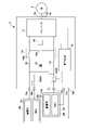
- FIG. 1 is a block diagram of a power supply device according to an embodiment of the present invention
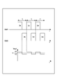
- FIG. 4 is a timing chart showing the relationship between the ON/OFF timing of each switching element and the output voltage
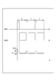
- 4 is a timing chart showing the relationship between the ON/OFF timing of each switching element and the output voltage
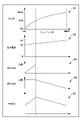
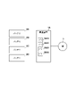
- FIG. 10 is a diagram showing the ratio of connection time and changes in power ratio, output voltage, individual output power, and total output power
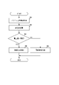
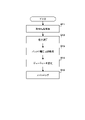
- 4 is a flowchart showing an example of processing executed by a control circuit
- 4 is a flowchart showing an example of processing executed by a control circuit
- FIG. 2 is a block diagram showing a modification of the power supply device of FIG. 1
- FIG. 4 is a block diagram showing another example of a power supply device with a different number of batteries
- FIG. 9 is a timing chart showing ON/OFF timing of each switching element in the example of FIG. 8;
- FIG. 1 is a block diagram of a power supply device 1 according to one embodiment of the present invention.
- the power supply device 1 is a device that uses a plurality of batteries 2A and 2B (collectively referred to or referred to as batteries 2 when not distinguished) as power sources, which are DC power sources, and supplies power to a load.
- the load is the motor 3, and the power supply device 1 also functions as a driving device for driving the motor 3, and can be used as a driving device for driving the motor of a vehicle, for example.
- the present invention can be applied to power supply devices that supply power to various loads, and can also be applied to stationary power supplies, portable power supplies, and the like.
- each battery 2 is a detachable battery, particularly a mobile battery pack detachable from the power supply device 1 .
- each battery 2 may be fixedly provided with the power supply device 1, and some of the batteries may be mobile battery packs, and the remaining batteries may be batteries fixedly provided in the power supply device 1. good too.
- Each battery 2 includes a power storage unit 2a and a BMU (management system) 2b that manages the power storage unit 2a.
- the power storage unit 2a stores electric power output from the battery 2, and is configured by, for example, connecting a plurality of battery cells in series.
- the battery cells are, for example, lithium-ion battery cells.
- the BMU 2b communicates with a processor that controls charging and discharging of the power storage unit 2a, a storage device such as a semiconductor memory that stores programs executed by the processor and information about the state of the power storage unit 2a, an input/output interface, and a control circuit 19, which will be described later. Includes a communication interface that performs
- the BMU 2b also includes a detection circuit that detects the remaining amount, charging/discharging current, and charging/discharging voltage of the power storage unit 2a, and the processor controls the upper limit of the discharge power of the battery 2 and the charging amount based on the detection result of the detection circuit. do. For example, when the discharged power of the battery 2 reaches the upper limit, the processor controls discharging of the power storage unit 2a so as to maintain the discharged power of the battery 2 at the upper limit.
- the motor 3 is an AC motor, such as a three-phase brushless motor.
- a power supply device 1 converts a DC voltage output from a battery 2 into an AC voltage to drive a motor 3 .
- the power supply device 1 includes terminals 10a, 10b, and 10c to which the battery 2A is electrically connected, and terminals 11a, 11b, and 11c to which the battery 2B is electrically connected.
- a positive terminal of the battery 2 is connected to the terminals 10a and 11a, and a negative terminal of the battery 2 is connected to the terminals 10b and 11b.
- Communication terminals of the BMU 2b of the battery 2 are connected to the terminals 10c and 11c.
- the power supply device 1 includes a DC wiring 12 on the high potential side and a DC wiring 13 on the low potential side. A potential difference (voltage) between the DC wiring 12 and the DC wiring 13 is called an output voltage Vout.
- the power supply device 1 also includes a plurality of switching elements SW1 and SW2.
- the DC wiring 12 is connected to the terminal 10a through the switching element SW1, and is also connected to the terminal 11a through the switching element SW2.
- DC wiring 13 is connected to terminals 10b and 11b. With such a configuration, a plurality of batteries 2A and 2B are connected in parallel to DC wirings 12 and 13.
- the switching elements SW1 and SW2 are, for example, transistors, and individually switch the connecting/disconnecting of the plurality of batteries 2A and 2B to the DC wirings 12 and 13 according to the control signal from the control circuit 19 .
- the switching element SW1 connects the positive terminal of the battery 2A and the DC wiring 12 when turned on, and disconnects the positive terminal of the battery 2A and the DC wiring 12 when turned off.
- Switching element SW2 connects the positive terminal of battery 2B and DC wiring 12 when turned ON, and disconnects the positive terminal of battery 2B and DC wiring 12 when turned OFF.
- a diode 15 is provided between the DC wiring 12 and the DC wiring 13 to regulate the flow of current from the DC wiring 13 to the DC wiring 12 .
- the power supply device 1 also includes a smoothing circuit 14 that smoothes the output voltage Vout of the DC wirings 12 and 13 .
- the smoothing circuit 14 is an LC filter circuit including an inductor 14 a connected in series with the DC wiring 12 and a capacitor 14 b connected between the DC wiring 12 and the DC wiring 13 .
- the power supply device 1 includes an inverter 17.
- An output voltage Vout is input to the inverter 17 , and the inverter 17 converts the output voltage Vout, which is a DC voltage, into an AC voltage and outputs the AC voltage from a three-phase terminal 18 to the motor 3 .
- the inverter 17 includes, for example, an H-bridge circuit having four FETs (Field Effect Transistors) and a control circuit that sequentially switches the FETs on and off, and converts the output voltage Vout into a single-phase AC voltage.
- a voltage detection circuit 16 detects an output voltage Vout input to the inverter 17 .
- the power supply device 1 includes a control circuit 19 .
- the control circuit 19 includes, for example, a processor, a storage device such as a semiconductor memory, an input/output interface, a communication interface, and the like.
- the storage device stores programs executed by the processor, data used for processing by the processor, and the like.
- the control circuit 19 is communicably connected to the BMU 2b of each battery 2 via terminals 10c and 11c, and can acquire output capability information from the BMU 2b.
- the output capability information is state information related to the power that the battery 2 can currently output, such as remaining amount information (SOC: remaining capacity/fully charged capacity ⁇ 100), voltage information (each output voltage V1, V2), etc. information.
- the control circuit 19 is also communicably connected to the control circuit of the inverter 17 .
- the control circuit 19 is also connected to the voltage detection circuit 16 and can acquire the detection result from the voltage detection circuit 16 .
- the control circuit 19 switches the connection mode of the batteries 2A and 2B to the DC wirings 12 and 13 by controlling the ON/OFF of the switching elements SW1 and SW2. In the mode in which both the batteries 2A and 2B are connected to the DC wirings 12 and 13, the power that can be supplied to the inverter 17 is maximized. However, if the difference between the output voltages of batteries 2A and 2B is large, current can flow from one battery to the other. In this embodiment, since the batteries 2A and 2B are replaceable mobile battery packs, the difference between the output voltages of the batteries 2A and 2B is likely to be large. In such a case, it is conceivable to continuously connect only one of the batteries to the DC wiring 12 and 13, but the power consumption of that battery increases, causing its deterioration, or the frequency of charging and replacement increases. may become.
- the control circuit 19 executes connection switching control to alternately connect the batteries 2A and 2B to the DC wirings 12 and 13, thereby efficiently using the plurality of batteries 2A and 2B.
- FIG. 2 is an explanatory diagram thereof.
- t indicates the passage of time
- T indicates unit time.
- the unit time T is set as one cycle, and within the unit time T, one of the batteries 2A and 2B connected to the DC wirings 12 and 13 is sequentially switched repeatedly.
- the unit time T is, for example, a time within the range of 50 ⁇ s to 1 ms.
- V1 indicates the output voltage of battery 2A
- V2 indicates the output voltage of battery 2B. In the illustrated example, there is a relationship of V1>V2.
- the output voltage Vout is the output voltage V1 when the switching element SW1 is on and the switching element SW2 is off, and the output voltage Vout is the output voltage V2 when the switching element SW2 is on and the switching element SW1 is off.
- the output voltage Vout becomes the voltage V when averaged over the unit time T.
- the ON time of the switching element SW1 (connection time of the battery 2A) and the ON time of the switching element SW2 (connection time of the battery 2B) are both T/2.
- the ratio of ON/OFF time in the unit time T is expressed as a duty ratio
- the duty ratio of the switching element SW1 is 50%
- the duty ratio of the switching element SW2 is 50%.
- the temporal waveform of the output voltage Vout is a signal that alternately repeats V1 and V2. Even if the difference between V1 and V2 is large, the output voltage Vout is smoothed by the smoothing circuit 14 and input to the inverter 17 because the smoothing circuit 14 is provided in this embodiment.
- the average power drawn from battery 2A is 3 kw and the average power drawn from battery 2B is 2 kw.
- the control circuit 19 can change the connection time of each battery 2A and 2B to the DC wirings 12 and 13, that is, the duty ratio.
- FIG. 3 shows an example in which the duty ratio is changed.
- the duty ratio of the switching element SW1 is 20%
- the duty ratio of the switching element SW2 is 80%.
- FIG. 4 shows the relationship between the duty ratio of the switching element SW1 and the power ratio between the battery 2A and the battery 2B (graph G1), the relationship with the output voltage (graph G2), and the output of the battery 2A when V1>V2.
- the relationship with the possible power W1-max (graph G3), the relationship with the possible output power W2-max of the battery 2B (graph G4), and the relationship with the possible output power to the inverter 17 (graph G5) are shown.
- the duty ratio in FIG. 4 represents the duty ratio of the switching element SW1
- the duty ratio of the switching element SW2 is 100%.
- the duty ratio of the switching element SW2 is 0%.
- the horizontal axes of the graphs G1 to G5 all represent the duty ratio of the switching element SW1.
- the output voltage (Vout) is the output voltage V2 of the battery 2B
- the output voltage (Vout) is the output voltage V1 of the battery 2A ( G2).
- the output voltage changes depending on the duty ratio.
- a graph G3 shows the output power W1-max of only the battery 2A in a unit time T.
- Possible output power W1-max increases as the duty ratio increases from 0%.
- the discharge power of the battery 2A reaches the upper limit (for example, the discharge current upper limit), and the output is regulated by the BMU 2b of the battery 2A.
- the available power W1-max does not increase.
- a graph G4 shows the possible output power W2-max of only the battery 2B in a unit time T.
- the duty ratio of the switching element SW2 increases from 0%, so the output power W2-max increases.
- the discharge power of the battery 2B reaches the upper limit (for example, the discharge current upper limit), the output is regulated by the BMU 2b of the battery 2B, and then the duty ratio decreases (switching element SW2 (the duty ratio of ) does not increase the outputtable power W2-max.
- a graph G5 shows the power W-max that can be output to the inverter 17 in a unit time T, which is the sum of the powers W1-max and W2-max that can be output from the batteries 2A and 2B.
- the outputtable power W-max is maximized at the duty ratio at which the power ratio is 50%, and the outputtable power W-max decreases regardless of whether the duty ratio is increased or decreased.
- By controlling the duty ratio it is possible to control the output voltage Vout and the output power W-max while protecting the battery 2 by regulating the discharge power of the battery 2 by the BMU 2b.
- FIG. 5 is a flow chart showing an example of processing for selecting control modes of the switching elements SW1 and SW2.
- the processor of the control circuit 19 periodically executes the processing shown in FIG.
- S1 the voltage information of the batteries 2A and 2B (the output voltages V1 and V2) of the batteries 2A and 2B is obtained by communication from the BMUs 2b of the batteries 2A and 2B.
- S2 the voltage difference between the output voltages (V1, V2) obtained in S1 is calculated.
- the threshold is, for example, a value within the range of 1.5V, or a value between 1% and 3% of the average value of each output voltage (V1, V2).
- both the switching elements SW1 and SW2 are controlled to be ON. Larger power can be supplied to the motor 3, which is the load, than in connection switching control.
- connection switching control of S4 it is possible to efficiently use these batteries 2 while preventing current from flowing between the batteries 2A and 2B.
- FIG. 6 is a flowchart showing an example of drive control of the switching elements SW1 and SW2 that is executed when the connection switching control of S4 is selected, and is periodically executed at a shorter cycle than the process of FIG.
- the detection result of the output voltage Vout is acquired from the voltage detection circuit 16 .
- the difference between the output voltage Vout obtained in S11 and the target output voltage is calculated.
- the voltage information of the batteries 2A and 2B (the output voltages V1 and V2) of the batteries 2A and 2B is obtained by communication from the BMUs 2b of the batteries 2A and 2B.
- the duty ratios of the switching elements SW1 and SW2 are set so that the difference calculated in S12 becomes small.
- the duty ratio is set within the range of 0% ⁇ duty ratio ⁇ 100%.
- switching of the switching elements SW1 and SW2 is executed at the duty ratio set at S14. Through the above processing, the output voltage Vout can be maintained at the target output voltage.
- the switching elements SW1 and SW2 are provided in the DC wiring 12 on the high potential side, but they may be provided in the DC wiring 13 on the low potential side.
- FIG. 7 shows an example thereof. In the illustrated example, both the switching elements SW1 and SW2 are provided in the DC wiring 13 . A configuration in which some of the switching elements are provided in the DC wiring 12 and the remaining switching elements are provided in the DC wiring 13 can also be adopted.
- the control mode of the switching elements SW1 and SW2 is selected based on the voltage information acquired from the BMU 2b (S1 to S3), but the control mode is selected based on the output capability information other than the voltage information.
- connection switching control may be executed when the difference in SOC between the batteries 2A and 2B exceeds a predetermined value, and simultaneous connection control may be executed when the difference is equal to or less than the predetermined value.
- FIG. 8 is a block diagram showing a power supply device 1A to which four batteries 2A-2D can be connected.
- the configuration of the power supply device 1A is the same as the configuration of FIG. can be switched to
- FIG. 9 is an explanatory diagram of connection switching control in the configuration example of FIG. In the illustrated example, each duty ratio of the switching elements SW1 to SW4 is 25%.
- the power supply device 1 in FIG. 1 includes the inverter 17 and is configured to output AC power.
- the configuration may be such that the output voltage Vout is directly supplied to an external load without including the inverter 17 .
- connection switching control when the voltage difference is equal to or less than the threshold in S3 has been described (S5).
- S5 an example of selecting simultaneous connection control when the voltage difference is equal to or less than the threshold in S3 has been described (S5).
- Another condition is, for example, the case where the required power of the load exceeds a predetermined threshold. If other conditions are not satisfied, connection switching control may be selected even if the voltage difference is equal to or less than the threshold.
- the power supply device (1, 1A) of the above embodiment includes: High potential side and low potential side wiring (12, 13) to which a plurality of batteries (2) are connected in parallel; a plurality of switching means (SW) for individually switching the connection and disconnection of the plurality of batteries with respect to the wiring; a control means (19) for controlling the plurality of switching means;
- a power supply device comprising: The control means is Connection switching control is executed to sequentially switch one of the plurality of batteries connected to the wiring within a unit time (S4). According to this embodiment, it is possible to provide a power supply device that efficiently uses a plurality of batteries with easy control.
- connection switching control the connection time of each battery to the wiring within the unit time can be changed (S14). According to this embodiment, the DC output voltage can be controlled.
- the power supply device of the above embodiment includes: A detection means (16) for detecting the output voltage of the wiring,
- the control means is In the connection switching control, the connection time of each battery to the wiring within the unit time is changed based on the detection result of the detection means (S11, S14). According to this embodiment, the DC output voltage can be controlled according to the target voltage.
- the control means determines whether or not to execute the connection switching control based on the output capability information of each of the plurality of batteries (S3). According to this embodiment, when there is a difference in output capability between the batteries, the connection switching control is executed to utilize the batteries.
- the control means executes the connection switching control when the output voltage difference between the plurality of batteries exceeds a predetermined value (S3, S4). According to this embodiment, when there is a possibility that a current may flow between the batteries, the connection switching control is executed to prevent such a situation and utilize the batteries.
- the control means executes control to simultaneously connect the plurality of batteries to the wiring on condition that the output voltage difference between the plurality of batteries is equal to or less than a predetermined value (S3, S5). This embodiment allows more power to be supplied to the load.
- the power supply device of the above embodiment includes: A smoothing circuit (S14) is provided for smoothing the output voltage of the wiring. According to this embodiment, even if one battery connected to the wiring is sequentially switched, an averaged and stable voltage can be output.
- each of the plurality of batteries is a mobile battery pack equipped with a management system (2b);
- the control means is communicable with the management system. According to this embodiment, information about the state of the mobile battery pack can be obtained from the management system.
- the management system controls the upper limit of the discharge power of the battery. According to this embodiment, a plurality of batteries can be efficiently used while protecting the batteries.
- the power supply device of the above embodiment includes: An inverter (17) is provided for converting the output voltage (Vout) of the wiring into an AC voltage. According to this embodiment, power can be supplied to a load that consumes AC power.
- At least one of the plurality of batteries is a removable battery. According to this embodiment, detachable batteries with different usage states and deterioration states can be effectively used.
Landscapes
- Engineering & Computer Science (AREA)
- Power Engineering (AREA)
- Secondary Cells (AREA)
- Charge And Discharge Circuits For Batteries Or The Like (AREA)
- Prostheses (AREA)
- Apparatus For Radiation Diagnosis (AREA)
- Heat-Pump Type And Storage Water Heaters (AREA)
- Direct Current Feeding And Distribution (AREA)
- Keying Circuit Devices (AREA)
Abstract
Description
複数のバッテリが並列に接続される、高電位側及び低電位側の配線と、
前記配線に対する前記複数のバッテリの断続を個別に切り替える複数のスイッチング手段と、
前記複数のスイッチング手段を制御する制御手段と、
を備えた電源装置であって、
前記制御手段は、
単位時間内で、前記複数のバッテリのうち前記配線に接続する一のバッテリを、順次切り替える接続切替制御を実行する、
ことを特徴とする電源装置が提供される。
制御回路19はスイッチング素子SW1及びSW2のオン・オフを制御することにより、直流配線12及び13に対するバッテリ2A及び2Bの接続態様を切り替える。バッテリ2A及び2Bの双方が直流配線12及び13に接続された態様においては、インバータ17に供給可能な電力が最大となる。しかし、バッテリ2A及び2Bの各出力電圧の差が大きい場合、一方のバッテリから他方のバッテリに電流が流れ得る。本実施形態では、バッテリ2A及び2Bが交換可能なモバイルバッテリパックであるため、両者の出力電圧の差が大きい場合が生じやすい。こうした場合に、一方のバッテリのみを継続的に直流配線12及び13に接続することも考えられるが、そのバッテリの電力消費が大きくなり、その劣化を生じたり、或いは、充電や交換の頻度が高くなる場合がある。
制御回路19のプロセッサが実行する処理例について説明する。図5は、スイッチング素子SW1及びSW2の制御態様を選択する処理例を示すフローチャートである。制御回路19のプロセッサは同図の処理を周期的に実行する。S1では、バッテリ2A及び2Bの各BMU2bから、バッテリ2A及び2Bの電圧情報(各出力電圧V1、V2)を通信により取得する。S2ではS1で取得した各出力電圧(V1、V2)の電圧差を演算する。S3ではS2で演算した電圧差(=|V1-V2|)が閾値を超えるか否かを判定する。閾値は、例えば、1.5Vの範囲内の値、或いは、各出力電圧(V1、V2)の平均値の1%~3%の値である。
上記実施形態では、スイッチング素子SW1及びSW2を高電位側の直流配線12に設けたが、低電位側の直流配線13に設けてもよい。図7はその一例を示す。図示の例ではスイッチング素子SW1及びSW2がいずれも直流配線13に設けられている。なお、一部のスイッチング素子を直流配線12に、残りのスイッチング素子を直流配線13に、それぞれ設ける構成も採用可能である。
上記実施形態は、少なくとも以下の電源装置を開示している。
複数のバッテリ(2)が並列に接続される、高電位側及び低電位側の配線(12,13)と、
前記配線に対する前記複数のバッテリの断続を個別に切り替える複数のスイッチング手段(SW)と、
前記複数のスイッチング手段を制御する制御手段(19)と、
を備えた電源装置であって、
前記制御手段は、
単位時間内で、前記複数のバッテリのうち前記配線に接続する一のバッテリを、順次切り替える接続切替制御を実行する(S4)。
この実施形態によれば、容易な制御で複数のバッテリを効率よく用いる電源装置を提供することができる。
前記接続切替制御では、前記配線に対する各バッテリの、前記単位時間内での接続時間を変更可能である(S14)。
この実施形態によれば、直流出力電圧を制御することができる。
前記配線の出力電圧を検知する検知手段(16)を備え、
前記制御手段は、
前記接続切替制御において、前記検知手段の検知結果に基づいて、前記配線に対する各バッテリの、前記単位時間内での接続時間を変更する(S11,S14)。
この実施形態によれば、目標とする電圧に応じて直流出力電圧を制御することができる。
前記制御手段は、前記複数のバッテリの各出力能力情報に基づいて、前記接続切替制御を実行するか否かを判定する(S3)。
この実施形態によれば、前記バッテリ間で出力能力に差がある場合に前記接続切替制御を実行して、前記バッテリの活用を図れる。
前記制御手段は、前記複数のバッテリ間の出力電圧差が所定値を超える場合に、前記接続切替制御を実行する(S3,S4)。
この実施形態によれば、前記バッテリ間で電流が流れるおそれがある場合に前記接続切替制御を実行して、その防止を図りつつ、前記バッテリの活用を図れる。
前記制御手段は、前記複数のバッテリ間の出力電圧差が所定値以下であることを条件として、前記複数のバッテリを同時に前記配線に接続する制御を実行する(S3,S5)。
この実施形態によれば、より大きな電力を負荷に供給できる。
前記配線の出力電圧を平滑化する平滑化回路(S14)を備える。
この実施形態によれば、前記配線に接続する一のバッテリを順次切り替えても、平均化された安定した電圧を出力することができる。
前記複数のバッテリは、それぞれ、マネジメントシステム(2b)を備えたモバイルバッテリパックであり、
前記制御手段は、前記マネジメントシステムと通信可能である。
この実施形態によれば、前記マネジメントシステムから、前記モバイルバッテリパックの状態に係る情報を得ることができる。
前記マネジメントシステムは、前記バッテリの放電電力の上限を制御する。
この実施形態によれば、前記バッテリの保護を図りつつ、複数のバッテリを効率よく用いることができる。
前記配線の出力電圧(Vout)を、交流電圧に変換するインバータ(17)を備える。
この実施形態によれば、交流電力を消費する負荷に電力を供給できる。
前記複数のバッテリの少なくとも一つは、着脱型のバッテリである。
この実施形態によれば、利用状態や劣化状態が異なる着脱型のバッテリを効果的に利用することができる。
Claims (11)
- 複数のバッテリが並列に接続される、高電位側及び低電位側の配線と、
前記配線に対する前記複数のバッテリの断続を個別に切り替える複数のスイッチング手段と、
前記複数のスイッチング手段を制御する制御手段と、
を備えた電源装置であって、
前記制御手段は、
単位時間内で、前記複数のバッテリのうち前記配線に接続する一のバッテリを、順次切り替える接続切替制御を実行する、
ことを特徴とする電源装置。 - 請求項1に記載の電源装置であって、
前記接続切替制御では、前記配線に対する各バッテリの、前記単位時間内での接続時間を変更可能である、
ことを特徴とする電源装置。 - 請求項1に記載の電源装置であって、
前記配線の出力電圧を検知する検知手段を備え、
前記制御手段は、
前記接続切替制御において、前記検知手段の検知結果に基づいて、前記配線に対する各バッテリの、前記単位時間内での接続時間を変更する、
ことを特徴とする電源装置。 - 請求項1乃至請求項3のいずれか一項に記載の電源装置であって、
前記制御手段は、前記複数のバッテリの各出力能力情報に基づいて、前記接続切替制御を実行するか否かを判定する、
ことを特徴とする電源装置。 - 請求項1乃至請求項3のいずれか一項に記載の電源装置であって、
前記制御手段は、前記複数のバッテリ間の出力電圧差が所定値を超える場合に、前記接続切替制御を実行する、
ことを特徴とする電源装置。 - 請求項1乃至請求項3のいずれか一項に記載の電源装置であって、
前記制御手段は、前記複数のバッテリ間の出力電圧差が所定値以下であることを条件として、前記複数のバッテリを同時に前記配線に接続する制御を実行する、
ことを特徴とする電源装置。 - 請求項1乃至請求項6のいずれか一項に記載の電源装置であって、
前記配線の出力電圧を平滑化する平滑化回路を備える、
ことを特徴とする電源装置。 - 請求項1乃至請求項7のいずれか一項に記載の電源装置であって、
前記複数のバッテリは、それぞれ、マネジメントシステムを備えたモバイルバッテリパックであり、
前記制御手段は、前記マネジメントシステムと通信可能である、
ことを特徴とする電源装置。 - 請求項8に記載の電源装置であって、
前記マネジメントシステムは、前記バッテリの放電電力の上限を制御する、
ことを特徴とする電源装置。 - 請求項1乃至請求項9のいずれか一項に記載の電源装置であって、
前記配線の出力電圧を、交流電圧に変換するインバータを備える、
ことを特徴とする電源装置。 - 請求項1に記載の電源装置であって、
前記複数のバッテリの少なくとも一つは、着脱型のバッテリである、
ことを特徴とする電源装置。
Priority Applications (3)
| Application Number | Priority Date | Filing Date | Title |
|---|---|---|---|
| JP2023508348A JP7549125B2 (ja) | 2021-03-25 | 2021-03-25 | 電源装置 |
| PCT/JP2021/012691 WO2022201466A1 (ja) | 2021-03-25 | 2021-03-25 | 電源装置 |
| TW111101588A TWI818409B (zh) | 2021-03-25 | 2022-01-14 | 電源裝置 |
Applications Claiming Priority (1)
| Application Number | Priority Date | Filing Date | Title |
|---|---|---|---|
| PCT/JP2021/012691 WO2022201466A1 (ja) | 2021-03-25 | 2021-03-25 | 電源装置 |
Publications (1)
| Publication Number | Publication Date |
|---|---|
| WO2022201466A1 true WO2022201466A1 (ja) | 2022-09-29 |
Family
ID=83395485
Family Applications (1)
| Application Number | Title | Priority Date | Filing Date |
|---|---|---|---|
| PCT/JP2021/012691 Ceased WO2022201466A1 (ja) | 2021-03-25 | 2021-03-25 | 電源装置 |
Country Status (3)
| Country | Link |
|---|---|
| JP (1) | JP7549125B2 (ja) |
| TW (1) | TWI818409B (ja) |
| WO (1) | WO2022201466A1 (ja) |
Citations (5)
| Publication number | Priority date | Publication date | Assignee | Title |
|---|---|---|---|---|
| JPH0946914A (ja) * | 1995-07-31 | 1997-02-14 | Oki Electric Ind Co Ltd | 電源供給装置及びその充電装置 |
| JPH11252812A (ja) * | 1998-02-27 | 1999-09-17 | Nec Yonezawa Ltd | バッテリ放電制御方法および装置 |
| JP2015050813A (ja) * | 2013-08-30 | 2015-03-16 | ミツミ電機株式会社 | 電池保護回路、電池保護装置及び電池パック、並びに電池保護方法 |
| JP2016012984A (ja) * | 2014-06-30 | 2016-01-21 | 日立化成株式会社 | 電池システム |
| JP2016019303A (ja) * | 2014-07-04 | 2016-02-01 | 株式会社マキタ | バッテリパック |
Family Cites Families (3)
| Publication number | Priority date | Publication date | Assignee | Title |
|---|---|---|---|---|
| US9662988B2 (en) * | 2014-12-09 | 2017-05-30 | Honda Motor Co., Ltd. | System and method for power management of off-board loads being powered and/or charged by an electric vehicle |
| KR102692156B1 (ko) * | 2018-02-21 | 2024-08-07 | 삼성전자주식회사 | 외부 전자 장치와 연결된 신호 단자에 감지된 전압의 크기에 따라 외부 전자 장치로 출력하는 전압을 제어 하기 위한 방법 및 전자 장치 |
| CN110682828B (zh) * | 2019-10-15 | 2021-07-02 | 北京牛电信息技术有限责任公司 | 并联双电池包的控制方法以及控制系统 |
-
2021
- 2021-03-25 WO PCT/JP2021/012691 patent/WO2022201466A1/ja not_active Ceased
- 2021-03-25 JP JP2023508348A patent/JP7549125B2/ja active Active
-
2022
- 2022-01-14 TW TW111101588A patent/TWI818409B/zh active
Patent Citations (5)
| Publication number | Priority date | Publication date | Assignee | Title |
|---|---|---|---|---|
| JPH0946914A (ja) * | 1995-07-31 | 1997-02-14 | Oki Electric Ind Co Ltd | 電源供給装置及びその充電装置 |
| JPH11252812A (ja) * | 1998-02-27 | 1999-09-17 | Nec Yonezawa Ltd | バッテリ放電制御方法および装置 |
| JP2015050813A (ja) * | 2013-08-30 | 2015-03-16 | ミツミ電機株式会社 | 電池保護回路、電池保護装置及び電池パック、並びに電池保護方法 |
| JP2016012984A (ja) * | 2014-06-30 | 2016-01-21 | 日立化成株式会社 | 電池システム |
| JP2016019303A (ja) * | 2014-07-04 | 2016-02-01 | 株式会社マキタ | バッテリパック |
Also Published As
| Publication number | Publication date |
|---|---|
| JPWO2022201466A1 (ja) | 2022-09-29 |
| JP7549125B2 (ja) | 2024-09-10 |
| TW202239102A (zh) | 2022-10-01 |
| TWI818409B (zh) | 2023-10-11 |
Similar Documents
| Publication | Publication Date | Title |
|---|---|---|
| EP2036186B1 (en) | Charge equalization apparatus with parallel connection of secondary windings of multiple transformers | |
| US8736231B2 (en) | Power management circuit for rechargeable battery stack | |
| CN102655340B (zh) | 电源系统 | |
| JP5484860B2 (ja) | 電力供給装置 | |
| JP6639686B2 (ja) | セルバランシングシステム及び制御方法 | |
| EP2879266A1 (en) | Power management method for a stacked cell rechargeable energy storage and stacked cell rechargeable energy storage device | |
| JP2004364500A (ja) | バッテリ電源システムで電源を負荷にスイッチングするためのアーキテクチャ | |
| WO2018139337A1 (ja) | 電気機器 | |
| KR20160098863A (ko) | 휴대용 배터리팩 | |
| WO2013048539A1 (en) | Voltage management device for a stacked battery | |
| JP2009247145A (ja) | 電源システム | |
| KR102939412B1 (ko) | 에너지 저장 시스템 및 배터리 성능을 개선하기 위한 방법 | |
| US10243383B2 (en) | Power source and electronic device | |
| JP7549125B2 (ja) | 電源装置 | |
| JP4144009B2 (ja) | 可変電圧型蓄電装置およびハイブリッド型電源装置 | |
| JP3303740B2 (ja) | 電池パックの放電制御装置 | |
| KR20210047750A (ko) | 배터리 관리 시스템 및 밸런싱 방법 | |
| KR20210007554A (ko) | 전원 시스템 | |
| KR101500709B1 (ko) | 배터리 수명 향상이 가능한 에너지 저장 장치 | |
| CN115152121A (zh) | 蓄电装置的电池组控制电路的电力供给方式及蓄电装置 | |
| JP6591683B2 (ja) | 充電電圧の供給装置及び供給方法 | |
| CN221263373U (zh) | 设有基本电池组和增压电池组的直流供电系统 | |
| JP2023155930A (ja) | 直列充電制御装置及びこれを備えたバッテリ装置 | |
| JP2025121600A (ja) | 電池パック、及び電池パックシステム | |
| CN121536159A (zh) | 能量存储装置、包括该装置的车辆电源及车载电网 |
Legal Events
| Date | Code | Title | Description |
|---|---|---|---|
| 121 | Ep: the epo has been informed by wipo that ep was designated in this application |
Ref document number: 21933071 Country of ref document: EP Kind code of ref document: A1 |
|
| WWE | Wipo information: entry into national phase |
Ref document number: 2023508348 Country of ref document: JP |
|
| WWE | Wipo information: entry into national phase |
Ref document number: 202317062880 Country of ref document: IN |
|
| NENP | Non-entry into the national phase |
Ref country code: DE |
|
| 122 | Ep: pct application non-entry in european phase |
Ref document number: 21933071 Country of ref document: EP Kind code of ref document: A1 |