WO2022201441A1 - 帳票仕分けシステム、ロボット制御方法、及び、記録媒体 - Google Patents
帳票仕分けシステム、ロボット制御方法、及び、記録媒体 Download PDFInfo
- Publication number
- WO2022201441A1 WO2022201441A1 PCT/JP2021/012598 JP2021012598W WO2022201441A1 WO 2022201441 A1 WO2022201441 A1 WO 2022201441A1 JP 2021012598 W JP2021012598 W JP 2021012598W WO 2022201441 A1 WO2022201441 A1 WO 2022201441A1
- Authority
- WO
- WIPO (PCT)
- Prior art keywords
- forms
- robot
- sorting
- sorting system
- conveyor
- Prior art date
- Legal status (The legal status is an assumption and is not a legal conclusion. Google has not performed a legal analysis and makes no representation as to the accuracy of the status listed.)
- Ceased
Links
Images






Classifications
-
- B—PERFORMING OPERATIONS; TRANSPORTING
- B25—HAND TOOLS; PORTABLE POWER-DRIVEN TOOLS; MANIPULATORS
- B25J—MANIPULATORS; CHAMBERS PROVIDED WITH MANIPULATION DEVICES
- B25J9/00—Program-controlled manipulators
- B25J9/16—Program controls
- B25J9/1679—Program controls characterised by the tasks executed
-
- B—PERFORMING OPERATIONS; TRANSPORTING
- B25—HAND TOOLS; PORTABLE POWER-DRIVEN TOOLS; MANIPULATORS
- B25J—MANIPULATORS; CHAMBERS PROVIDED WITH MANIPULATION DEVICES
- B25J9/00—Program-controlled manipulators
- B25J9/0093—Program-controlled manipulators co-operating with conveyor means
-
- B—PERFORMING OPERATIONS; TRANSPORTING
- B25—HAND TOOLS; PORTABLE POWER-DRIVEN TOOLS; MANIPULATORS
- B25J—MANIPULATORS; CHAMBERS PROVIDED WITH MANIPULATION DEVICES
- B25J9/00—Program-controlled manipulators
- B25J9/16—Program controls
- B25J9/1694—Program controls characterised by use of sensors other than normal servo-feedback from position, speed or acceleration sensors, perception control, multi-sensor controlled systems, sensor fusion
- B25J9/1697—Vision controlled systems
-
- B—PERFORMING OPERATIONS; TRANSPORTING
- B65—CONVEYING; PACKING; STORING; HANDLING THIN OR FILAMENTARY MATERIAL
- B65G—TRANSPORT OR STORAGE DEVICES, e.g. CONVEYORS FOR LOADING OR TIPPING, SHOP CONVEYOR SYSTEMS OR PNEUMATIC TUBE CONVEYORS
- B65G47/00—Article or material-handling devices associated with conveyors; Methods employing such devices
- B65G47/74—Feeding, transfer, or discharging devices of particular kinds or types
- B65G47/90—Devices for picking-up and depositing articles or materials
-
- B—PERFORMING OPERATIONS; TRANSPORTING
- B65—CONVEYING; PACKING; STORING; HANDLING THIN OR FILAMENTARY MATERIAL
- B65H—HANDLING THIN OR FILAMENTARY MATERIAL, e.g. SHEETS, WEBS, CABLES
- B65H39/00—Associating, collating, or gathering articles or webs
- B65H39/10—Associating articles from a single source, to form, e.g. a writing-pad
-
- B—PERFORMING OPERATIONS; TRANSPORTING
- B65—CONVEYING; PACKING; STORING; HANDLING THIN OR FILAMENTARY MATERIAL
- B65H—HANDLING THIN OR FILAMENTARY MATERIAL, e.g. SHEETS, WEBS, CABLES
- B65H39/00—Associating, collating, or gathering articles or webs
- B65H39/10—Associating articles from a single source, to form, e.g. a writing-pad
- B65H39/115—Associating articles from a single source, to form, e.g. a writing-pad in juxtaposed carriers
-
- B—PERFORMING OPERATIONS; TRANSPORTING
- B65—CONVEYING; PACKING; STORING; HANDLING THIN OR FILAMENTARY MATERIAL
- B65H—HANDLING THIN OR FILAMENTARY MATERIAL, e.g. SHEETS, WEBS, CABLES
- B65H5/00—Feeding articles separated from piles; Feeding articles to machines
- B65H5/08—Feeding articles separated from piles; Feeding articles to machines by grippers, e.g. suction grippers
- B65H5/14—Details of grippers; Actuating-mechanisms therefor
-
- B—PERFORMING OPERATIONS; TRANSPORTING
- B65—CONVEYING; PACKING; STORING; HANDLING THIN OR FILAMENTARY MATERIAL
- B65H—HANDLING THIN OR FILAMENTARY MATERIAL, e.g. SHEETS, WEBS, CABLES
- B65H2301/00—Handling processes for sheets or webs
- B65H2301/10—Selective handling processes
- B65H2301/13—Relative to size or orientation of the material
- B65H2301/133—Face-up or face-down handling mode
-
- B—PERFORMING OPERATIONS; TRANSPORTING
- B65—CONVEYING; PACKING; STORING; HANDLING THIN OR FILAMENTARY MATERIAL
- B65H—HANDLING THIN OR FILAMENTARY MATERIAL, e.g. SHEETS, WEBS, CABLES
- B65H2301/00—Handling processes for sheets or webs
- B65H2301/40—Type of handling process
- B65H2301/44—Moving, forwarding, guiding material
- B65H2301/443—Moving, forwarding, guiding material by acting on surface of handled material
- B65H2301/4432—Moving, forwarding, guiding material by acting on surface of handled material by means having an operating surface contacting only one face of the material, e.g. roller
-
- B—PERFORMING OPERATIONS; TRANSPORTING
- B65—CONVEYING; PACKING; STORING; HANDLING THIN OR FILAMENTARY MATERIAL
- B65H—HANDLING THIN OR FILAMENTARY MATERIAL, e.g. SHEETS, WEBS, CABLES
- B65H2301/00—Handling processes for sheets or webs
- B65H2301/40—Type of handling process
- B65H2301/44—Moving, forwarding, guiding material
- B65H2301/443—Moving, forwarding, guiding material by acting on surface of handled material
- B65H2301/4433—Moving, forwarding, guiding material by acting on surface of handled material by means holding the material
- B65H2301/44334—Moving, forwarding, guiding material by acting on surface of handled material by means holding the material using electrostatic forces
-
- B—PERFORMING OPERATIONS; TRANSPORTING
- B65—CONVEYING; PACKING; STORING; HANDLING THIN OR FILAMENTARY MATERIAL
- B65H—HANDLING THIN OR FILAMENTARY MATERIAL, e.g. SHEETS, WEBS, CABLES
- B65H2301/00—Handling processes for sheets or webs
- B65H2301/40—Type of handling process
- B65H2301/44—Moving, forwarding, guiding material
- B65H2301/445—Moving, forwarding, guiding material stream of articles separated from each other
- B65H2301/4451—Moving, forwarding, guiding material stream of articles separated from each other forming a stream or streams of separated articles
-
- B—PERFORMING OPERATIONS; TRANSPORTING
- B65—CONVEYING; PACKING; STORING; HANDLING THIN OR FILAMENTARY MATERIAL
- B65H—HANDLING THIN OR FILAMENTARY MATERIAL, e.g. SHEETS, WEBS, CABLES
- B65H2408/00—Specific machines
- B65H2408/10—Specific machines for handling sheet(s)
- B65H2408/11—Sorters or machines for sorting articles
- B65H2408/111—Sorters or machines for sorting articles with stationary location in space of the bins and a diverter per bin
-
- B—PERFORMING OPERATIONS; TRANSPORTING
- B65—CONVEYING; PACKING; STORING; HANDLING THIN OR FILAMENTARY MATERIAL
- B65H—HANDLING THIN OR FILAMENTARY MATERIAL, e.g. SHEETS, WEBS, CABLES
- B65H2553/00—Sensing or detecting means
- B65H2553/40—Sensing or detecting means using optical, e.g. photographic, elements
- B65H2553/42—Cameras
-
- B—PERFORMING OPERATIONS; TRANSPORTING
- B65—CONVEYING; PACKING; STORING; HANDLING THIN OR FILAMENTARY MATERIAL
- B65H—HANDLING THIN OR FILAMENTARY MATERIAL, e.g. SHEETS, WEBS, CABLES
- B65H2555/00—Actuating means
- B65H2555/30—Multi-axis
-
- G—PHYSICS
- G05—CONTROLLING; REGULATING
- G05B—CONTROL OR REGULATING SYSTEMS IN GENERAL; FUNCTIONAL ELEMENTS OF SUCH SYSTEMS; MONITORING OR TESTING ARRANGEMENTS FOR SUCH SYSTEMS OR ELEMENTS
- G05B2219/00—Program-control systems
- G05B2219/30—Nc systems
- G05B2219/39—Robotics, robotics to robotics hand
- G05B2219/39102—Manipulator cooperating with conveyor
-
- G—PHYSICS
- G05—CONTROLLING; REGULATING
- G05B—CONTROL OR REGULATING SYSTEMS IN GENERAL; FUNCTIONAL ELEMENTS OF SUCH SYSTEMS; MONITORING OR TESTING ARRANGEMENTS FOR SUCH SYSTEMS OR ELEMENTS
- G05B2219/00—Program-control systems
- G05B2219/30—Nc systems
- G05B2219/40—Robotics, robotics mapping to robotics vision
- G05B2219/40053—Pick 3-D object from pile of objects
-
- G—PHYSICS
- G05—CONTROLLING; REGULATING
- G05B—CONTROL OR REGULATING SYSTEMS IN GENERAL; FUNCTIONAL ELEMENTS OF SUCH SYSTEMS; MONITORING OR TESTING ARRANGEMENTS FOR SUCH SYSTEMS OR ELEMENTS
- G05B2219/00—Program-control systems
- G05B2219/30—Nc systems
- G05B2219/40—Robotics, robotics mapping to robotics vision
- G05B2219/40078—Sort objects, workpieces
-
- G—PHYSICS
- G05—CONTROLLING; REGULATING
- G05B—CONTROL OR REGULATING SYSTEMS IN GENERAL; FUNCTIONAL ELEMENTS OF SUCH SYSTEMS; MONITORING OR TESTING ARRANGEMENTS FOR SUCH SYSTEMS OR ELEMENTS
- G05B2219/00—Program-control systems
- G05B2219/30—Nc systems
- G05B2219/45—Nc applications
- G05B2219/45063—Pick and place manipulator
Definitions
- This disclosure relates to a form sorting system and the like.
- Convenience stores and other stores handle a wide variety of forms with different sizes and contents, including proxy storage forms, slips, gift certificates, and receipts. These forms are collected from each store at the accounting center and sorted manually. The contents of the classified forms are further manually registered in the system.
- Patent Document 1 describes a form sorting system that reads data written on a form handled by a financial institution, determines the type of the form from the data, and controls the sorting and storage of the form into storage means.
- a processing device is disclosed.
- an operator sets various types of payment slips mixed together as forms to be sorted in a hopper.
- the payment slips set in the hopper are fetched into the form sorting device one by one by the delivery rollers.
- Patent Document 1 discloses setting various types of payment slips in a hopper, but does not disclose handling payment slips of various sizes.
- forms sorted by size by an operator are set in a hopper by size.
- forms are set in an apparatus such as that disclosed in Patent Document 1 with the edges and corners of the forms aligned. Therefore, it takes time and effort for the operator.
- the present disclosure aims to provide a form sorting system or the like that streamlines the sorting of forms with a simple mechanism.
- a form sorting system includes recognition means for recognizing overlapping forms, a first control means for controlling a robot based on the result of the recognition, wherein the first control means causes the robot to hold one or more of the stacked forms; Each of the one or more forms is controlled so as not to overlap other forms by a conveying means that conveys the forms to the sorting mechanism.
- a robot control method recognizes overlapping forms, causes the robot to hold one or more of the overlapping forms based on the recognition result, and The robot is controlled so that each form is conveyed to the transport means for transporting the form to the sorting mechanism so as not to overlap other forms.
- a process for recognizing the positions of overlapping forms and a robot holding one or more of the overlapping forms based on the recognition result Non-temporarily recording a program for causing a computer to execute a process of controlling a robot to transport each of one or more forms to the sorting mechanism so that the forms are not overlapped with other forms.
- the efficiency of sorting forms can be improved with a simple mechanism.
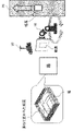
- FIG. 1 is a block diagram showing the configuration of a form sorting system 1 according to a first embodiment
- FIG. FIG. 3 is a diagram showing an arrangement example of a robot 10, a conveyor 20, and a camera 30
- 1 is a block diagram showing the configuration of a robot control device 100
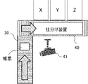
- FIG. FIG. 2 is a diagram showing an arrangement example of a conveyor 20 and a sorting device 40
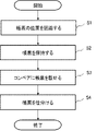
- 4 is a flowchart showing an operation example of the form sorting system 1 according to the first embodiment
- FIG. 5 is a diagram showing another arrangement example of the robot 10 and the conveyor 20
- FIG. 11 is a block diagram showing the configuration of a form sorting system 2 according to a second embodiment
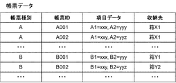
- 3 is a diagram showing an example of form data stored in a storage unit 205
- FIG. 4 is a flowchart showing an operation example of the form data generation device 200
- 5 is a block diagram showing an example of the hardware configuration of computer 500.
- a form is, for example, a substitute storage form, a slip, a gift certificate, a receipt, and other documents handled in a store or the like.
- the agency receipt form is, for example, a payment slip for charges such as gas, telephone, electricity, tax, social insurance, and electronic commerce.
- the type of form represents, for example, the classification based on the contents of these forms. Also, the type of form may indicate classification according to the size of the form.
- FIG. 1 is a block diagram showing the configuration of a form sorting system 1 according to the first embodiment.
- the form sorting system 1 has a robot 10 , a robot control device 100 , a conveyor 20 , a camera 30 , a sorting device 40 and a sorting control device 400 .
- the robot control device 100 is communicably connected to the robot 10 and the camera 30 by wire or wirelessly.
- the sorting control device 400 is communicably connected to the sorting device 40 by wire or wirelessly.
- the robot control device 100 and the sorting control device 400 may be communicably connected or may not communicate with each other.
- the robot 10 holds various types of forms set at predetermined locations and places them on the conveyor 20 .
- a camera 30 photographs a form set at a predetermined place.
- the conveyor 20 conveys the forms to the sorting device 40 .
- the conveyor 20 is, for example, a roller conveyor that conveys forms by rotating rollers arranged in parallel.
- Conveyor 20 may comprise a conveyor belt.
- Conveyor 20 is an embodiment of a conveying means.
- the sorting control device 400 causes the sorting device 40 to sort the forms.
- the sorting device 40 is, for example, a levitation type in which one set of rollers of two sets of rollers arranged at right angles rotates while floating to a position higher than the other set of rollers, thereby changing the conveying direction of the form. It is a transfer mechanism.
- the sorting device 40 rotates one set of rollers to change the conveying direction of the form to the direction of the sorting destination when the form to be sorted reaches the other set of rollers.
- the sorting device 40 is an embodiment of a sorting mechanism.
- the configuration of the sorting mechanism is not limited to the configuration described above, and may be changed to another configuration.
- the sorting device 40 sorts into sorting destinations according to the type of form (contents and size). For example, the sorting device 40 may sort the forms according to the paper size. Also, the forms may be sorted according to the contents such as proxy storage forms, slips, gift certificates, receipts, and other documents. The form may be sorted by subsequent processing steps, such as whether or not the form is to be input data, whether or not to be stored, and whether or not to be returned to the store. Forms may be further sorted by form name. If the form is a gift certificate, the gift certificate may be further sorted according to whether it is redeemable or not. Note that a plurality of different types of forms may be sorted into the same sorting destination.
- FIG. 2 is a diagram showing an arrangement example of the robot 10, the conveyor 20, and the camera 30.
- Forms collected from convenience stores can be put in bags and transported to each store. Information that uniquely identifies the store, for example, is attached to the bag. The worker may take out the form from the bag and put the form in a different box for each store.
- FIG. 3 is a block diagram showing the configuration of the robot control device 100. As shown in FIG. A robot controller 100 controls the robot 10 .
- the robot control device 100 includes a recognition section 101 and a control section 102 .
- the recognition unit 101 recognizes the overlapping forms based on the image captured by the camera 30 .
- the recognition unit 101 is an embodiment of recognition means.
- the recognition unit 101 may receive an image of the form captured from the camera 30 .
- the recognition unit 101 for example, recognizes the sides or corners of the form to recognize the position and size of the form.
- the recognition unit 101 may recognize the position and size of the form by recognizing the position of characters or codes printed on the form. Alternatively, the recognition unit 101 may receive the position and size of the form recognized by the camera 30 .
- the recognition unit 101 recognizes the topmost form in a box that does not have any overlapping forms.
- the recognition unit 101 recognizes a form whose sides, printed characters or codes are not hidden by other forms.
- the control unit 102 controls the robot 10 so that the robot 10 holds the form based on the recognition result of the recognition unit 101 and the robot 10 conveys the form to the conveyor 20 . That is, the robot 10 places the form on the conveyor 20 .
- the recognition result is, for example, the position or size of the form.
- the control unit 102 of the robot control device 100 is an embodiment of first control means.
- the robot 10 uses existing technology to hold, for example, the topmost form.
- the robot 10 may hold the form by gripping the sides of the form, for example, like human fingers.
- the robot 10 may attract the form to a flat plate or one or more contacts provided on the arm of the robot 10 by static electricity or by sucking or discharging air.
- the control unit 102 controls the robot 10 so that the form held by the robot 10 is conveyed to the conveyor 20 so that the form held by the robot 10 does not overlap other forms.
- the control unit 102 controls the robot to convey the form to the conveyor 20 in an empty space before and after another form being conveyed to the conveyor 20 .
- the control unit 102 controls the robot 10 to place the next form after a predetermined period of time has passed since one form was placed.
- the conveyor 20 conveys the form during the lapse of a predetermined time and creates a space for the next form. If the size of the form recognized by the recognition unit 101 is larger than that of other forms, the control unit 102 may make the time interval for placing the next form larger than the interval for placing other forms.
- a camera may be installed to photograph the conveyor 20, and the control unit 102 may control the robot 10 to place the form in the photographed space.
- the robot 10 may take out multiple forms from the box at once as long as the forms can be placed on the conveyor 20 without overlapping.
- the control unit 102 may hold two or more of the stacked forms and control the robot 10 to convey each of the two or more forms to the conveyor 20 .
- the sorting device 40 uses existing sorting technology to sort the forms according to their types to a plurality of sorting destination discharge units.
- the types of forms to be sorted to each sorting destination (discharge unit) are set in advance by an administrator or the like. Here, different types of forms may be sorted to the same sorting destination (discharge unit). At each sorting destination (discharge section), the forms can be stacked.
- the sorting control device 400 controls the sorting device 40 .
- the sorting control device 400 acquires the characteristics of the form, identifies the type of the form based on the acquired characteristics, and determines the sorting destination.
- the characteristics of a form are, for example, the shape, size, and color of the form, or characters and codes printed on the form. Characters printed on the form indicate, for example, the name of the form.
- the code printed on the form is, for example, a bar code or two-dimensional code indicating the type of the form.
- the sorting control device 400 may be communicatively connected to the camera 41 by wire or wirelessly in order to acquire the features of the form.
- the camera 41 photographs, for example, the form on the conveyor 20 .
- the sorting control device 400 acquires the features of the form based on the image. Note that an image scanner or barcode scanner may be used instead of the camera 41 .
- the sorting control device 400 may acquire the features of the form from the image captured by the camera 30.
- the robot control device 100 transmits images of the forms photographed by the camera 30 to the sorting control device 400 in the order in which the forms are placed on the conveyor 20 .
- the order of the forms whose images are received by the sorting control device 400 from the robot control device 100 corresponds to the order of the forms conveyed to the sorting device 40 by the conveyor 20 .
- the sorting control device 400 acquires the features of the forms from the images sequentially received from the robot control device 100 and causes the sorting device 40 to sort the forms conveyed in order.
- the sorting control device 400 receives from the robot control device 100 the characteristics of the form acquired based on the image of the form photographed by the camera 30 and the specified type of the form from the robot control device 100 . may
- the sorting control device 400 may be formed integrally with the sorting device 40, or may be provided as a separate device.
- Forms that have been sorted to the sorting destination may be further transported by workers or robots.
- an operator or a robot takes out a form from a sorting destination (discharge section) and carries it to another device in order to register the description of the form in the system.
- an operator or robot carries the form to a predetermined storage location.
- Storage locations are not particularly limited, for example, rooms, shelves, cases, boxes, containers, bags, files, folders, and the like.
- the worker may carry the forms together with the storage means.
- the type of storage means installed at the sorting destination (discharge section) is not particularly limited, and may be, for example, any of a case, a box, a container, and a bag.
- FIG. 4 is a diagram showing an arrangement example of the conveyor 20 and the sorting device 40.
- the sorting device 40 and the conveyor 20 may be integrally formed.
- storage means X, Y, and Z are installed at the sorting destination (discharge section).
- FIG. 5 is a flow chart showing an operation example of the form sorting system 1 according to the first embodiment.
- the recognition unit 101 of the robot control device 100 recognizes the position of the form (step S1).
- the controller 102 controls the robot 10 based on the recognized position.
- the robot 10 holds one form under the control of the control unit 102 (step S2). Further, the robot 10 places the held form on the conveyor 20 (step S3).
- the conveyor 20 conveys the forms to the sorting device 40 .
- the sorting device 40 sorts the forms according to their types (step S4). This completes the description of the operation example of the form sorting system 1 .
- the sorting of forms can be made more efficient with a simple mechanism.
- the robot 10 holds one or more of the overlapping forms and places each of the one or more forms on the conveyor 20 so as not to overlap with other forms.
- the conveyor 20 conveys the forms to the sorting device 40 .
- the sorting device 40 by using the sorting device 40, the sorting work by humans can be automated. As a result, even if the orientation, position, and size of the forms are not aligned, it is not necessary for the operator to align them.
- the sorting mechanism a simple mechanism for sorting the documents conveyed one by one can be used. Therefore, the forms can be efficiently sorted with a simple mechanism.
- the robot controller 100 recognizes the positions of the stacked forms and causes the robot 10 to hold the forms. Therefore, the operator can collectively set forms of various sizes. In addition, even if the operator stacks the forms somewhat disorderly, the sorting device 40 can efficiently sort the forms.
- the robot control device 100 may control the robot 10 so that the robot 10 places the forms on the conveyor 20 in the same vertical and horizontal directions.
- the robot 10 may arrange the forms on the conveyor 20 so that the arrangement angles of the upper ends of all the forms are aligned.
- top, bottom, left, and right orientations and arrangement angles of the forms on the conveyor 20 are aligned, it is expected that sorting errors due to the sorting mechanism and errors in acquiring the characteristics of the forms will be reduced.
- the forms since the forms are discharged to the sorting destination with the same orientation, when the storage means is installed at the sorting destination, the forms can be stored with the orientation aligned.
- the forms can be moved to the storage location without the operator or robot aligning the orientation. If the forms are stored in the same orientation, management becomes easier.
- the form sorting system 1 may further include a form reversing mechanism using existing technology and a control device for controlling the reversing mechanism.
- the inversion mechanism inverts the surface of the form on the conveyor 20. For example, when the reverse side of the form placed on the conveyor 20 faces upward, the reversing mechanism reverses the form so that the front side faces upward. With the surface facing upward, for example, the camera 41 can capture the features of the form appearing on the surface on the conveyor.
- the control device of the reversing mechanism recognizes the orientation of the form based on the image of the form received from any camera.
- the camera for recognizing the orientation of the form may be any of the camera 30 according to the first embodiment, another camera that captures images on the conveyor 20, and the camera 41 according to the second embodiment.
- the controller of the reversing mechanism is an embodiment of the second control means.
- the control device for the reversing mechanism may be provided integrally with the robot control device 100 or the sorting control device 400, or may be provided separately from these devices.
- FIG. 6 is a diagram showing another arrangement example of the robot 10 and the conveyor 20. As shown in FIG. In the example of FIG. 6, the robot 10-1 places the forms in the box Q on the conveyor 20, and the robot 10-2 places the forms in the box P on the conveyor 20, for example. The robot 10-1 places the form on the conveyor 20 so as not to overlap the form placed by the robot 10-2.
- the robots 10-1 and 10-2 may be controlled by one robot control device 100.
- a plurality of cameras 30 may be provided for each robot 10 or for each box in which forms are stacked.
- the robot controller 100 receives images of the forms stacked in each box from each camera 30 .
- one camera 30 may be provided, and one camera 30 may photograph the forms in each of a plurality of boxes.
- the robot 10-1 and the robot 10-2 may be controlled by different robot controllers 100, respectively.
- the conveyor 21 is a transport means that transports boxes containing stacked forms to the position of the robot 10 .
- the conveyor 21 may also carry empty boxes from which all the forms have been taken out by the robot 10 .
- FIG. 7 is a block diagram showing the configuration of a form sorting system 2 according to the second embodiment.
- the form sorting system 2 further includes a form data generation device 200 compared to the form sorting system 1 according to the first embodiment. A description of the same configuration as the configuration according to the first embodiment will be omitted.
- the form data generation device 200 may be communicably connected to the robot control device 100 and the sorting control device 400 by wire or wirelessly.
- the form data generation device 200 includes an image acquisition unit 201 , a reading unit 202 , a generation unit 203 , a storage destination acquisition unit 204 , and a storage unit 205 . Note that the form data generation device 200 may not include some of the above components. Also, each component of the form data generation device 200 may be implemented by a combination of a plurality of devices.
- the image acquisition unit 201 acquires an image of a form from a camera placed at an arbitrary position where the form to be sorted can be imaged.
- the image acquisition unit 201 may acquire, from the camera 30, an image of the form to be sorted set at the above location.
- the image acquisition unit 201 may acquire the image of the form on the conveyor 20 from the camera 41 used by the sorting control device 400 or another camera.
- the image acquisition unit 201 may acquire an image of the sorted form from a camera installed at each sorting destination (discharge unit).
- the image acquisition unit 201 acquires images from the cameras 30 and 41, there is no need to provide a camera for creating form data, which will be described later, in addition to the cameras 30 and 41, and costs can be reduced.
- the reading unit 202 reads the description of the form based on the image acquired by the image acquisition unit 201 .
- the reading unit 202 reads the description of the form by recognizing the text in the image by, for example, OCR (Optical Character Recognition) technology.
- the reading unit 202 may read the description of the form for each item included in the form.
- the generation unit 203 generates form data indicating the description of the form read by the reading unit 202 .
- the generation unit 203 causes the storage unit 205 to store the form data. Adding the form data to the storage unit 205 is also referred to as registering the form with the system.
- FIG. 8 is a diagram showing an example of form data stored in the storage unit 205. As shown in FIG.
- the form data includes the form type, form ID (Identifier), and item data.
- the form type indicates the type (contents and size) of the above-described form.
- the form type may indicate whether the form is a proxy receipt form, a slip, a gift certificate, a receipt, or other documents.
- the form type may indicate the form name or the size of the form.
- the type of the form is determined by the reading unit 202 in the same manner as the sorting control device 400, for example.
- a form ID is an identifier that uniquely identifies a form.
- the generation unit 203 may attach a form ID to the read form. Alternatively, the generation unit 203 may use the result of reading the form ID printed on the form by the reading unit 202 as the form ID.
- Item data is data that indicates the matters described for each item included in the form.
- the items included in the form may differ depending on the type (content) of the form.
- a form of form type A includes item A1 and item A2.
- the reading unit 202 reads that data xxx is described in item A1 and data yyy is described in A2 for the form with the form ID A001.
- the form data may further include the storage location of the read form.
- the storage destination is, for example, the identifier of the storage means installed at the sorting destination (discharge section). Also, the storage location may be an identifier that identifies the storage location where the form is stored. Also, the storage destination may be a combination of an identifier for identifying the storage location where the form is stored and the identifier of the storage means.
- the storage destination acquisition unit 204 acquires the storage destination of each form to be read.
- the storage destination acquisition unit 204 selects the storage destination where the form to be read is stored. get.
- the storage destination acquiring unit 204 (2)
- the identifier of the storage means in which the form is stored is specified from the image of the storage means photographed together with the form.
- the identifier of the storage means in which the form is stored is specified as follows. obtain.
- the storage destination acquiring unit 204 first acquires the form ID of the form to be read specified by the reading unit 202 . Further, the storage destination acquiring unit 204 acquires the form ID of the sorted form obtained from the image captured by the camera of each sorting destination (discharge unit) and the identifier of the storage means in which the relevant form is stored. The storage destination acquiring unit 204 identifies the identifier of the storage means in which the form is stored based on the acquired form ID and the identifier of the storage means.
- the storage means in which the form is stored identifier can be specified as follows: For example, the storage destination acquisition unit 204 obtains the order in which the forms are sorted to the sorting destination (discharge unit) based on the order of the images of the acquired forms (order of sorting by the sorting device 40) and the type of the forms. . Then, the image acquisition unit 201 determines the storage means in which the read forms are stored based on the number of forms stored in each storage means sequentially installed and replaced at the sorting destination (discharge part) and the identifier of the storage means. Identify an identifier.
- each storage means sequentially installed and exchanged at each sorting destination (discharge section) and the number of forms stored in the storage means may be input by the operator, or may be input by each sorting destination (discharge unit). It may be obtained from an image captured by a camera in the discharge section).
- the storage location acquisition unit 204 acquires the storage location where the read form is stored, for example, as follows.
- the storage destination acquisition unit 204 acquires the identifier of the storage location to which each storage means has been transported from an input from the worker or robot that transported the storage means. Then, the storage destination acquiring unit 204 identifies the document to be read based on the identifier of the storage means in which the document to be read is stored and the identifier of the storage location to which each storage means is transported, which is specified by the above-described method. Identify the identifier of the stored storage means.
- the A001 form is stored in the box X1.
- the storage destination it is possible to manage the actual form corresponding to the data.
- the form data may further include an image of the form. That is, the generation unit 203 may further store the image of the form acquired by the image acquisition unit 201 in the storage unit 205 . Then, the form data generating apparatus 200 may associate the stored form data with the image and display them on an arbitrary display. By displaying the image, the operator can compare the image with the read item data.
- FIG. 9 is a flow chart showing an operation example of the form data generation device 200. As shown in FIG.
- Step S21 acquires the image of the form (step S21).
- Step S21 may be performed before step S1 in FIG. 5 or after any of steps S1 to S4.
- the reading unit 202 reads the description of the form based on the acquired image of the form (step S22).
- the storage destination acquisition unit 204 acquires the storage destination of the form (step S23).
- the generation unit 203 generates form data including the description read by the reading unit 202 (step S24).
- each component of the robot control device 100 and the form data generation device 200 represents a functional unit block.
- a part or all of each component of each device may be realized by any combination of the computer 500 and a program.
- FIG. 10 is a block diagram showing an example of the hardware configuration of computer 500.
- computer 500 includes, for example, CPU (Central Processing Unit) 501, ROM (Read Only Memory) 502, RAM (Random Access Memory) 503, program 504, storage device 505, drive device 507, communication interface 508 , an input device 509 , an input/output interface 511 and a bus 512 .
- CPU Central Processing Unit
- ROM Read Only Memory
- RAM Random Access Memory
- the program 504 includes instructions for realizing each function of each device.
- the program 504 is stored in advance in the ROM 502 , RAM 503 and storage device 505 .
- the CPU 501 implements each function of each device by executing instructions included in the program 504 .
- the functions of the robot control device 100 are realized by the CPU 501 of the robot control device 100 executing commands included in the program 504 .
- the RAM 503 may store data processed in each function of each device.
- the RAM 503 of the computer 500 may store the document position in the robot control device 100 .
- the drive device 507 reads from and writes to the recording medium 506 .
- Communication interface 508 provides an interface with a communication network.
- the input device 509 is, for example, a mouse, a keyboard, or the like, and receives input of information from the administrator of the form sorting system 1 .
- the output device 510 is, for example, a display, and outputs (displays) information to an administrator or the like.
- the input/output interface 511 provides an interface with peripheral devices.
- a bus 512 connects each of these hardware components.
- the program 504 may be supplied to the CPU 501 via a communication network, or may be stored in the recording medium 506 in advance, read by the drive device 507 and supplied to the CPU 501 .
- FIG. 10 is an example, and components other than these may be added, and some components may not be included.
- each device may be implemented by any combination of a computer and a program that are different for each component.
- a plurality of components included in each device may be realized by any combination of a single computer and a program.
- each component of each device may be realized by a general-purpose or dedicated circuit including a processor or the like, or a combination thereof. These circuits may be composed of a single chip, or may be composed of multiple chips connected via a bus. A part or all of each component of each device may be realized by a combination of the above-described circuits and the like and programs.
- each component of each device when a part or all of each component of each device is realized by a plurality of computers, circuits, etc., the plurality of computers, circuits, etc. may be centrally arranged or distributed.
- At least part of the form sorting systems 1 and 2 may be provided in SaaS (Software as a Service) format. That is, at least part of the functions for realizing the robot control device 100 and the form data generation device 200 may be executed by software executed via a network.
- SaaS Software as a Service
- Robot 100 Robot Control Device 20, 21 Conveyor 30, 41 Camera 40 Sorting Device 400 Sorting Control Device 500 Computer
Landscapes
- Engineering & Computer Science (AREA)
- Mechanical Engineering (AREA)
- Robotics (AREA)
- Sorting Of Articles (AREA)
- Specific Conveyance Elements (AREA)
- Feeding Of Articles To Conveyors (AREA)
Abstract
Description
前記認識の結果に基づいて、ロボットを制御する第1の制御手段と、を備え、前記第1の制御手段は、前記ロボットが、前記重ねて置かれた帳票のうちの1以上を保持し、当該1以上の帳票の各々を、仕分け機構へ帳票を搬送する搬送手段に、他の帳票と重ならないように搬送させるように制御する。
(構成)
図1は、第1実施形態に係る帳票仕分けシステム1の構成を示すブロック図である。帳票仕分けシステム1は、ロボット10、ロボット制御装置100、コンベア20、カメラ30、仕分け装置40、及び、仕分け制御装置400を有する。ロボット制御装置100は、ロボット10及びカメラ30と有線または無線により通信可能に接続される。仕分け制御装置400は、仕分け装置40と有線または無線により通信可能に接続される。ロボット制御装置100と仕分け制御装置400は、通信可能に接続されてもよいし、通信を行わなくてもよい。
図5は、第1実施形態に係る帳票仕分けシステム1の動作例を示すフローチャートである。まず、ロボット制御装置100の認識部101は、帳票の位置を認識する(ステップS1)。制御部102は認識された位置に基づいてロボット10を制御する。ロボット10は制御部102からの制御に基づいて、帳票を1枚保持する(ステップS2)。さらに、ロボット10は、保持した帳票をコンベア20に載せる(ステップS3)。コンベア20は仕分け装置40へ帳票を搬送する。仕分け装置40は帳票を種別に応じて仕分ける(ステップS4)。以上で帳票仕分けシステム1の動作例の説明を終了する。
第1実施形態によれば、帳票の仕分けを簡単な機構で効率化できる。その理由は、ロボット10が重ねて置かれた帳票のうちの1以上を保持し、1以上の帳票の各々を、他の帳票と重ならないようにコンベア20に載せるためである。さらに、コンベア20が帳票を仕分け装置40へ搬送するためである。さらに、第1実施形態によれば、仕分け装置40を用いることで、人による仕分け作業を自動化できる。これにより、帳票の向きや位置、サイズが揃えられていない状態で置かれていても、作業者が揃える必要はない。また、仕分け機構として、1枚ずつ搬送されてきた帳票を仕分けるだけの簡単な機構を用いることができる。したがって、簡単な機構で効率的に帳票を仕分けることができる。
ロボット制御装置100は、ロボット10が、帳票の上下左右の向きを揃えてコンベア20に帳票を載せるよう、ロボットを制御してもよい。例えば、ロボット10は、全ての帳票の上端の配置角度が揃うように、帳票をコンベア20上に配置してもよい。
1つのレーンのコンベア20に対して、ロボット10は複数配置されてもよい。図6は、ロボット10とコンベア20の他の配置例を示す図である。図6の例において、ロボット10-1は、例えば、箱Q内の帳票をコンベア20に載せて、ロボット10-2は、箱P内の帳票をコンベア20に載せる。ロボット10-1は、ロボット10-2が載せた帳票に重ならないように帳票をコンベア20に載せる。
(構成)
図7は、第2実施形態に係る帳票仕分けシステム2の構成を示すブロック図である。帳票仕分けシステム2は、第1実施形態に係る帳票仕分けシステム1と比較して、帳票データ生成装置200をさらに備える。第1実施形態に係る構成と同様の構成については、説明を省略する。帳票データ生成装置200は、ロボット制御装置100及び仕分け制御装置400と、有線または無線により通信可能に接続されてもよい。
第2実施形態に係る帳票仕分けシステム2の動作例について説明する。ロボット10、ロボット制御装置100、コンベア20、及び、仕分け装置40の動作は第1実施形態と同様であるから、説明を省略する。図9は、帳票データ生成装置200の動作例を示すフローチャートである。
第2実施形態によれば、人が帳票を見て、帳票の記載をシステムに入力する作業を自動化できる。その理由は、画像取得部201が、帳票の画像を取得し、読取部202が、帳票の記載を読み取り、生成部203が帳票データを生成し、記憶部205に登録するためである。
上述した各実施形態において、ロボット制御装置100、及び帳票データ生成装置200の各構成要素は、機能単位のブロックを示している。各装置の各構成要素の一部又は全部は、コンピュータ500とプログラムとの任意の組み合わせにより実現されてもよい。
100 ロボット制御装置
20、21 コンベア
30、41 カメラ
40 仕分け装置
400 仕分け制御装置
500 コンピュータ
Claims (9)
- 重ねて置かれた帳票を認識する認識手段と、
前記認識の結果に基づいて、ロボットを制御する第1の制御手段と、を備え、
前記第1の制御手段は、前記ロボットが、前記重ねて置かれた帳票のうちの1以上を保持し、当該1以上の帳票の各々を、仕分け機構へ帳票を搬送する搬送手段に、他の帳票と重ならないように搬送させるように制御する、
帳票仕分けシステム。 - 前記第1の制御手段は、前記ロボットが、前記搬送手段に搬送されている前記他の帳票の前後の空いたスペースで、前記1以上の帳票を前記搬送手段に搬送させるように制御する、請求項1に記載の帳票仕分けシステム。
- 前記搬送手段における帳票の面を反転させるための反転機構を制御する、第2の制御手段を更に備える請求項1または2に記載の帳票仕分けシステム。
- 前記重ねて置かれた帳票を撮像した画像から、前記帳票の記載を読み取る読み取り手段と、
前記帳票の記載を示す帳票データを生成する生成手段と、を更に備える、
請求項1乃至3のいずれか1項に記載の帳票仕分けシステム。 - 前記搬送手段により搬送されている帳票、及び、前記仕分け機構により仕分けられた帳票のうちのいずれかを撮像した画像から、前記帳票の記載を読み取る読み取り手段と、
前記帳票の記載を示す帳票データを生成する生成手段と、を更に備える、
請求項1乃至3のいずれか1項に記載の帳票仕分けシステム。 - 前記生成手段は、前記帳票の画像を含む帳票データを更に生成する
請求項4または5に記載の帳票仕分けシステム。 - 前記生成手段は、前記帳票の収納先を含む帳票データを更に生成する
請求項4乃至6のいずれか1項に記載の帳票仕分けシステム。 - 重ねて置かれた帳票を認識し、
認識された結果に基づいて、ロボットが、前記重ねて置かれた帳票のうちの1以上を保持し、当該1以上の帳票の各々を、仕分け機構へ帳票を搬送する搬送手段に、他の帳票と重ならないように搬送させるようにロボットを制御する
ロボット制御方法。 - 重ねて置かれた帳票の位置を認識する処理と、
認識された結果に基づいて、ロボットが、前記重ねて置かれた帳票のうちの1以上を保持し、当該1以上の帳票の各々を、仕分け機構へ帳票を搬送する搬送手段に、他の帳票と重ならないように搬送させるようにロボットを制御する処理とをコンピュータに実行させるプログラムを非一時的に記録する記録媒体。
Priority Applications (3)
| Application Number | Priority Date | Filing Date | Title |
|---|---|---|---|
| PCT/JP2021/012598 WO2022201441A1 (ja) | 2021-03-25 | 2021-03-25 | 帳票仕分けシステム、ロボット制御方法、及び、記録媒体 |
| JP2023508324A JP7529894B2 (ja) | 2021-03-25 | 2021-03-25 | 帳票仕分けシステム、ロボット制御方法、及び、プログラム |
| US18/268,697 US20240042612A1 (en) | 2021-03-25 | 2021-03-25 | Form sorting system, robot control method, and recording medium |
Applications Claiming Priority (1)
| Application Number | Priority Date | Filing Date | Title |
|---|---|---|---|
| PCT/JP2021/012598 WO2022201441A1 (ja) | 2021-03-25 | 2021-03-25 | 帳票仕分けシステム、ロボット制御方法、及び、記録媒体 |
Publications (1)
| Publication Number | Publication Date |
|---|---|
| WO2022201441A1 true WO2022201441A1 (ja) | 2022-09-29 |
Family
ID=83395426
Family Applications (1)
| Application Number | Title | Priority Date | Filing Date |
|---|---|---|---|
| PCT/JP2021/012598 Ceased WO2022201441A1 (ja) | 2021-03-25 | 2021-03-25 | 帳票仕分けシステム、ロボット制御方法、及び、記録媒体 |
Country Status (3)
| Country | Link |
|---|---|
| US (1) | US20240042612A1 (ja) |
| JP (1) | JP7529894B2 (ja) |
| WO (1) | WO2022201441A1 (ja) |
Citations (5)
| Publication number | Priority date | Publication date | Assignee | Title |
|---|---|---|---|---|
| JPH082712A (ja) * | 1994-04-11 | 1996-01-09 | Takasaki Seishi Kk | 板状材料の自動分離取り上げ方法とその装置 |
| JP2000118715A (ja) * | 1998-10-07 | 2000-04-25 | Hitachi Zosen Corp | 吸着装置 |
| JP2002234615A (ja) * | 2001-02-07 | 2002-08-23 | Shibuya Kogyo Co Ltd | 物品重ね合わせ装置 |
| JP2003211096A (ja) * | 2002-01-18 | 2003-07-29 | Fuji Photo Film Co Ltd | 物品の仕分け・整列装置 |
| JP2006143369A (ja) * | 2004-11-17 | 2006-06-08 | Glory Ltd | 帳票仕分け処理装置、帳票仕分け処理方法 |
-
2021
- 2021-03-25 JP JP2023508324A patent/JP7529894B2/ja active Active
- 2021-03-25 US US18/268,697 patent/US20240042612A1/en active Pending
- 2021-03-25 WO PCT/JP2021/012598 patent/WO2022201441A1/ja not_active Ceased
Patent Citations (5)
| Publication number | Priority date | Publication date | Assignee | Title |
|---|---|---|---|---|
| JPH082712A (ja) * | 1994-04-11 | 1996-01-09 | Takasaki Seishi Kk | 板状材料の自動分離取り上げ方法とその装置 |
| JP2000118715A (ja) * | 1998-10-07 | 2000-04-25 | Hitachi Zosen Corp | 吸着装置 |
| JP2002234615A (ja) * | 2001-02-07 | 2002-08-23 | Shibuya Kogyo Co Ltd | 物品重ね合わせ装置 |
| JP2003211096A (ja) * | 2002-01-18 | 2003-07-29 | Fuji Photo Film Co Ltd | 物品の仕分け・整列装置 |
| JP2006143369A (ja) * | 2004-11-17 | 2006-06-08 | Glory Ltd | 帳票仕分け処理装置、帳票仕分け処理方法 |
Also Published As
| Publication number | Publication date |
|---|---|
| JPWO2022201441A1 (ja) | 2022-09-29 |
| JP7529894B2 (ja) | 2024-08-06 |
| US20240042612A1 (en) | 2024-02-08 |
Similar Documents
| Publication | Publication Date | Title |
|---|---|---|
| EP1872869A2 (en) | Sort scheme generation based on bin capacity | |
| US8249997B2 (en) | Method and system for integrated pallet and sort scheme maintenance | |
| US20170066597A1 (en) | Information processing device, information processing system, distribution system, information processing method, and program storage medium | |
| CN109127445B (zh) | 条码读取方法及条码读取系统 | |
| US9463945B2 (en) | Multi-stage collation system and method for high speed compiling sequentially ordered signage | |
| JP2008516868A (ja) | アイテム管理システム及び関連方法 | |
| CN111570309A (zh) | 一种物流包裹分拣方法、装置及相关设备 | |
| JP2000219317A (ja) | 荷役仕分け装置 | |
| JP2008047105A (ja) | 様々な印刷製品のための検証システム | |
| US20240383139A1 (en) | Robotic Multi-Line Picking | |
| US6504946B1 (en) | Method of processing misoriented items in an image-based item processing system and an apparatus therefor | |
| JP7529894B2 (ja) | 帳票仕分けシステム、ロボット制御方法、及び、プログラム | |
| CN113935637A (zh) | 打包控制方法、装置、电子设备、打包系统和存储介质 | |
| CN113537917A (zh) | 货柜管理辅助系统及方法 | |
| US7127080B2 (en) | Method of processing image data to reorient an image represented by the image data in an image-based item processing system and an apparatus therefor | |
| JP4401204B2 (ja) | 納品検収システム | |
| JP2016533991A (ja) | 搬送システムによって運ばれる物品にデータを対応付ける搬送システム及び方法 | |
| JP7768333B2 (ja) | 帳票処理システム、帳票処理方法及びプログラム | |
| JP7772192B2 (ja) | 帳票処理システム、帳票処理方法及びプログラム | |
| JP3715459B2 (ja) | 郵便物処理装置及び郵便物処理方法 | |
| CN116486346B (zh) | 一种纸箱输送的方法与装置 | |
| JP2020045194A (ja) | 搬送システム | |
| CN110369298A (zh) | 用于包裹分拣的预处理系统及方法 | |
| JP6470118B2 (ja) | 配達物処理装置、配達物処理支援装置、配達物処理システム、配達物処理プログラム、および配達物処理支援プログラム | |
| JP2001113233A5 (ja) |
Legal Events
| Date | Code | Title | Description |
|---|---|---|---|
| 121 | Ep: the epo has been informed by wipo that ep was designated in this application |
Ref document number: 21933049 Country of ref document: EP Kind code of ref document: A1 |
|
| WWE | Wipo information: entry into national phase |
Ref document number: 18268697 Country of ref document: US |
|
| ENP | Entry into the national phase |
Ref document number: 2023508324 Country of ref document: JP Kind code of ref document: A |
|
| NENP | Non-entry into the national phase |
Ref country code: DE |
|
| 122 | Ep: pct application non-entry in european phase |
Ref document number: 21933049 Country of ref document: EP Kind code of ref document: A1 |