WO2022196746A1 - 電気化学キャパシタ - Google Patents
電気化学キャパシタ Download PDFInfo
- Publication number
- WO2022196746A1 WO2022196746A1 PCT/JP2022/012119 JP2022012119W WO2022196746A1 WO 2022196746 A1 WO2022196746 A1 WO 2022196746A1 JP 2022012119 W JP2022012119 W JP 2022012119W WO 2022196746 A1 WO2022196746 A1 WO 2022196746A1
- Authority
- WO
- WIPO (PCT)
- Prior art keywords
- negative electrode
- electrode
- positive electrode
- capacity
- electrochemical capacitor
- Prior art date
- Legal status (The legal status is an assumption and is not a legal conclusion. Google has not performed a legal analysis and makes no representation as to the accuracy of the status listed.)
- Ceased
Links
Images


Classifications
-
- H—ELECTRICITY
- H01—ELECTRIC ELEMENTS
- H01G—CAPACITORS; CAPACITORS, RECTIFIERS, DETECTORS, SWITCHING DEVICES, LIGHT-SENSITIVE OR TEMPERATURE-SENSITIVE DEVICES OF THE ELECTROLYTIC TYPE
- H01G11/00—Hybrid capacitors, i.e. capacitors having different positive and negative electrodes; Electric double-layer [EDL] capacitors; Processes for the manufacture thereof or of parts thereof
- H01G11/22—Electrodes
-
- H—ELECTRICITY
- H01—ELECTRIC ELEMENTS
- H01G—CAPACITORS; CAPACITORS, RECTIFIERS, DETECTORS, SWITCHING DEVICES, LIGHT-SENSITIVE OR TEMPERATURE-SENSITIVE DEVICES OF THE ELECTROLYTIC TYPE
- H01G11/00—Hybrid capacitors, i.e. capacitors having different positive and negative electrodes; Electric double-layer [EDL] capacitors; Processes for the manufacture thereof or of parts thereof
- H01G11/22—Electrodes
- H01G11/26—Electrodes characterised by their structure, e.g. multi-layered, porosity or surface features
-
- H—ELECTRICITY
- H01—ELECTRIC ELEMENTS
- H01G—CAPACITORS; CAPACITORS, RECTIFIERS, DETECTORS, SWITCHING DEVICES, LIGHT-SENSITIVE OR TEMPERATURE-SENSITIVE DEVICES OF THE ELECTROLYTIC TYPE
- H01G11/00—Hybrid capacitors, i.e. capacitors having different positive and negative electrodes; Electric double-layer [EDL] capacitors; Processes for the manufacture thereof or of parts thereof
- H01G11/22—Electrodes
- H01G11/30—Electrodes characterised by their material
-
- H—ELECTRICITY
- H01—ELECTRIC ELEMENTS
- H01G—CAPACITORS; CAPACITORS, RECTIFIERS, DETECTORS, SWITCHING DEVICES, LIGHT-SENSITIVE OR TEMPERATURE-SENSITIVE DEVICES OF THE ELECTROLYTIC TYPE
- H01G11/00—Hybrid capacitors, i.e. capacitors having different positive and negative electrodes; Electric double-layer [EDL] capacitors; Processes for the manufacture thereof or of parts thereof
- H01G11/22—Electrodes
- H01G11/30—Electrodes characterised by their material
- H01G11/32—Carbon-based
- H01G11/38—Carbon pastes or blends; Binders or additives therein
-
- H—ELECTRICITY
- H01—ELECTRIC ELEMENTS
- H01G—CAPACITORS; CAPACITORS, RECTIFIERS, DETECTORS, SWITCHING DEVICES, LIGHT-SENSITIVE OR TEMPERATURE-SENSITIVE DEVICES OF THE ELECTROLYTIC TYPE
- H01G11/00—Hybrid capacitors, i.e. capacitors having different positive and negative electrodes; Electric double-layer [EDL] capacitors; Processes for the manufacture thereof or of parts thereof
- H01G11/54—Electrolytes
- H01G11/58—Liquid electrolytes
-
- H—ELECTRICITY
- H01—ELECTRIC ELEMENTS
- H01G—CAPACITORS; CAPACITORS, RECTIFIERS, DETECTORS, SWITCHING DEVICES, LIGHT-SENSITIVE OR TEMPERATURE-SENSITIVE DEVICES OF THE ELECTROLYTIC TYPE
- H01G11/00—Hybrid capacitors, i.e. capacitors having different positive and negative electrodes; Electric double-layer [EDL] capacitors; Processes for the manufacture thereof or of parts thereof
- H01G11/54—Electrolytes
- H01G11/58—Liquid electrolytes
- H01G11/60—Liquid electrolytes characterised by the solvent
-
- H—ELECTRICITY
- H01—ELECTRIC ELEMENTS
- H01G—CAPACITORS; CAPACITORS, RECTIFIERS, DETECTORS, SWITCHING DEVICES, LIGHT-SENSITIVE OR TEMPERATURE-SENSITIVE DEVICES OF THE ELECTROLYTIC TYPE
- H01G11/00—Hybrid capacitors, i.e. capacitors having different positive and negative electrodes; Electric double-layer [EDL] capacitors; Processes for the manufacture thereof or of parts thereof
- H01G11/54—Electrolytes
- H01G11/58—Liquid electrolytes
- H01G11/62—Liquid electrolytes characterised by the solute, e.g. salts, anions or cations therein
-
- Y—GENERAL TAGGING OF NEW TECHNOLOGICAL DEVELOPMENTS; GENERAL TAGGING OF CROSS-SECTIONAL TECHNOLOGIES SPANNING OVER SEVERAL SECTIONS OF THE IPC; TECHNICAL SUBJECTS COVERED BY FORMER USPC CROSS-REFERENCE ART COLLECTIONS [XRACs] AND DIGESTS
- Y02—TECHNOLOGIES OR APPLICATIONS FOR MITIGATION OR ADAPTATION AGAINST CLIMATE CHANGE
- Y02E—REDUCTION OF GREENHOUSE GAS [GHG] EMISSIONS, RELATED TO ENERGY GENERATION, TRANSMISSION OR DISTRIBUTION
- Y02E60/00—Enabling technologies; Technologies with a potential or indirect contribution to GHG emissions mitigation
- Y02E60/13—Energy storage using capacitors
Definitions
- the present invention relates to electrochemical capacitors.
- An electrochemical capacitor includes a pair of electrodes and an electrolytic solution, and at least one of the pair of electrodes contains an active material capable of adsorbing and desorbing ions.
- An electric double-layer capacitor which is an example of an electrochemical capacitor, has a longer life than a secondary battery, can be rapidly charged, and has excellent output characteristics, and is widely used as a backup power source and the like.
- Patent Document 1 as a non-aqueous electrolyte for an electric double layer capacitor, N-ethyl-N-methylpyrrolidinium tetrafluoroborate is dissolved as a quaternary ammonium salt, and K + is added as an alkali metal cation at 28.
- An example containing 3 ppm and 0.4 ppm Na + is described (Example 1).
- Electrochemical capacitors tend to lose performance under float charging, and further improvements are required.
- one aspect of the present invention includes a positive electrode, a negative electrode, a separator interposed between the positive electrode and the negative electrode, and an electrolytic solution, wherein the electrolytic solution contains a lactone compound, and the capacity of the positive electrode is relates to an electrochemical capacitor that is larger than the capacity of the negative electrode and 1.6 times or less than the capacity of the negative electrode.
- deterioration of the float characteristics of the electrochemical capacitor can be suppressed.
- FIG. 1 is a partially cutaway perspective view of an electrochemical capacitor according to one embodiment of the present invention.
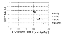
- FIG. 2 is a graph plotting the rate of increase in resistance after the float test of the electrochemical capacitor against the potential of the positive electrode (Ag/Ag + reference) when charged at 3V.
- FIG. 3 is a graph plotting the capacity deterioration rate after the float test of the electrochemical capacitor against the potential of the positive electrode (Ag/Ag + reference) when charged at 3V.
- An electrochemical capacitor according to one embodiment of the present invention includes a positive electrode, a negative electrode, a separator interposed between the positive electrode and the negative electrode, and an electrolytic solution.
- the electrolyte contains a lactone compound.
- the capacity of the positive electrode is greater than the capacity of the negative electrode and is 1.6 times or less than the capacity of the negative electrode. This configuration can improve the float characteristics.
- the float characteristic is an index of the degree of deterioration of an electrochemical device when float charging is performed using an external DC power supply to maintain a constant voltage. It can be said that the smaller the decrease in capacity during float charging and the smaller the increase in internal resistance, the better the float characteristics.
- the capacity of the positive electrode is the maximum value of the capacity that can be expressed in the positive electrode, and is a theoretical capacity determined according to the amount of the positive electrode active material and the like.
- the negative electrode capacity is the maximum value of the capacity that can be expressed in the negative electrode, and is a theoretical capacity that is determined according to the amount of the negative electrode active material and the like.
- the capacity of the positive electrode is roughly defined by the amount of the positive electrode active material loaded per unit area (g/cm 2 ) and the capacity per unit weight of the positive electrode active material (F/g ) is the value obtained by multiplying
- the capacity of the negative electrode is roughly defined by the amount of the negative electrode active material loaded per unit area (g/cm 2 ) and the capacity per unit weight of the negative electrode active material (F/g ) is the value obtained by multiplying
- the capacity (F) of the positive electrode active material and the negative electrode active material is obtained from the amount of charged electricity or the amount of accumulated electric charge when 3V is applied.
- Lactone compounds have low viscosity even at low temperatures, so they are used as solvents for electrolytes in electrochemical capacitors.
- Lactone compounds include ⁇ -propiolactone, ⁇ -butyrolactone, ⁇ -valerolactone, ⁇ -valerolactone and the like.
- ⁇ -butyrolactone GBL is most preferred because it has a low viscosity even at low temperatures, a high boiling point, and a small amount of gas released due to side reactions.
- the lactone compound may be decomposed by being placed in a strong oxidizing environment.
- float charging a state in which a high voltage is applied to the electrochemical capacitor continues for a long period of time, so a state in which the potential of the positive electrode continues to be high for a long period of time, and the lactone compound is susceptible to oxidative decomposition. As a result, it is considered that the float characteristics are degraded.
- the potential of the positive electrode during charging can be lowered by making the capacity of the positive electrode larger than the capacity of the negative electrode.
- the oxidative decomposition of the lactone compound is suppressed, and the deterioration of the float characteristics can be suppressed.
- the capacity of the positive electrode is preferably 1.1 times or more the capacity of the negative electrode.
- the larger the capacity of the positive electrode relative to the capacity of the negative electrode the larger the portion of the capacity of the positive electrode that does not contribute to the capacity of the electrical capacitor, and the smaller the capacity of the electrochemical capacitor.
- the reducing property is further enhanced on the negative electrode side.
- the capacity of the positive electrode is made 1.6 times or less the capacity of the negative electrode in order to suppress a decrease in the capacity of the electrochemical capacitor and to suppress a side reaction due to reductive decomposition at the negative electrode.
- the capacity of the positive electrode is preferably 1.1 times or more and 1.6 times or less than the capacity of the negative electrode in order to keep the capacity of the electrochemical capacitor high while suppressing the deterioration of the float characteristics.
- the positive electrode of the electrochemical capacitor may be a polarizable electrode.
- a polarizable electrode may comprise an active material capable of adsorbing and desorbing ions.
- capacity is developed by adsorption of ions to the active material.
- a non-faradaic current flows when ions are desorbed from the active material.
- the negative electrode may be a polarizable electrode or a non-polarizable electrode.
- the electrochemical capacitor may be an electric double layer capacitor (EDLC) in which an electric double layer is formed by adsorbing ions to the active material.
- EDLC electric double layer capacitor
- the electrochemical capacitor may be a lithium ion capacitor (LIC) that develops capacity by adsorption or desorption of lithium ions on the negative electrode side.
- LIC lithium ion capacitor
- the negative electrode used in lithium ion secondary batteries may be used as the negative electrode.
- the electrode body is usually configured such that the outermost periphery serves as the negative electrode.
- a polarizable electrode includes, for example, a current collector and a polarizable electrode layer supported by the current collector.
- the positive electrode includes, for example, a positive electrode current collector and a polarizable electrode layer supported by the positive electrode current collector.
- the negative electrode includes, for example, a negative electrode current collector and a polarizable electrode layer carried on the negative electrode current collector.
- the capacities of the positive electrode and the negative electrode depend on the loading amount of the active material contained in the polarizable electrode layer, and also on the specific surface area of the active material when the capacity is expressed by ion adsorption to the active material. However, by making the polarizable electrode layer of the positive electrode thicker than the polarizable electrode layer of the negative electrode, the capacity of the positive electrode can be easily made larger than that of the negative electrode.
- the capacity of the positive electrode may be larger than that of the negative electrode.
- the thickness of the polarizable electrode layer of the positive electrode is preferably greater than the thickness of the polarizable electrode layer of the negative electrode and 1.6 times or less than the thickness of the polarizable electrode layer of the negative electrode.
- the thickness of the polarized electrode layer of the positive electrode is more preferably 1.1 to 1.6 times the thickness of the polarized electrode layer of the negative electrode.
- the binder when a binder is included in the positive electrode and/or the negative electrode, the binder preferably has high resistance to reduction. Binders with high resistance to reduction include styrene-butadiene rubber (SBR). Styrene-butadiene rubber (SBR) includes styrene-butadiene copolymers and modifications thereof.
- SBR styrene-butadiene rubber
- the styrene-butadiene rubber is preferably contained in at least the polarizable electrode layer of the negative electrode.
- a quaternary ammonium ion is preferably used as the ion (cation) contained in the electrolytic solution.
- the electrolytic solution may contain pyrrolidinium ions. Pyrrolidinium ions have high resistance to reduction and are not easily decomposed at the negative electrode. Therefore, even when the capacity of the positive electrode is larger than the capacity of the negative electrode and the reducibility of the negative electrode is further enhanced, the pyrrolidinium ions are stable, and the generation of gas due to decomposition at the negative electrode is suppressed. Therefore, deterioration of float characteristics can be further suppressed.
- the pyrrolidinium ion is a quaternary ammonium ion represented by C 4 H 8 N + —R 1 R 2 (R 1 and R 2 are hydrocarbon groups), in which the nitrogen of the pyrrolidine ring is quaternized. R 1 and R 2 may each independently be a C1-C4 alkyl group.
- Examples of pyrrolidinium ions include N,N-dimethylpyrrolidinium (DMPy), N-methyl-N-ethylpyrrolidinium (MEPy), N,N-diethylpyrrolidinium (DEPy) and the like.
- a quaternary ammonium ion is added to the electrolyte in the form of a salt with an anion.
- the anion is preferably an anion containing fluorine. It preferably contains an anion of a fluorine-containing acid. Examples of fluorine-containing anions include BF 4 ⁇ and PF 6 ⁇ .
- the potential of the positive electrode is +0.86 V or more and +0.96 V or less based on the Ag/Ag + potential (the potential of the negative electrode is -2 .14 V or more and -2.04 V or less). In this case, it is possible to realize an electrochemical capacitor in which deterioration of float characteristics is significantly suppressed.
- the potential of the positive electrode (negative electrode) was 3 V, and the positive electrode and the negative electrode after charging were immersed in a non-aqueous solution having the same composition as the electrolytic solution so that the active material layers (polarizable electrode layers) faced each other.
- Positive electrode is used as a counter electrode, and the potential is measured when the Ag electrode is used as a reference electrode.
- the positive electrode and the negative electrode have active material layers (polarizable electrode layers) on both sides, one side of the active material layer (polarizable electrode layer) is removed so as not to form a non-facing portion.
- the Ag electrode was a reference electrode obtained by adding a solvent (GBL) to the electrolytic solution so that the salt concentration was 0.1 mol/L, and then adding AgBF 4 so that the Ag + ion concentration was 0.1 mol/L.
- a glass tube filled with the internal solution for the reference electrode and a silver wire immersed in the internal solution for the reference electrode can be used.
- an electrode comprising an active layer (polarizable electrode layer) containing an active material and a current collector supporting the active layer is used as a polarizable electrode.
- the active material includes, for example, porous carbon particles.
- the active layer contains porous carbon particles as an active material as an essential component, and may contain a binder, a conductive agent and the like as optional components.
- Porous carbon particles can be produced, for example, by heat-treating a raw material to carbonize it, and then activating the resulting carbide to make it porous.
- the carbide may be crushed and granulated before the activation treatment.
- the porous carbon particles obtained by the activation treatment may be pulverized. After the pulverization treatment, a classification treatment may be performed. Examples of the activation treatment include gas activation using a gas such as water vapor, and chemical activation using an alkali such as potassium hydroxide.
- Raw materials include, for example, wood, coconut shells, pulp waste liquid, coal or coal-based pitch obtained by thermal decomposition thereof, heavy oil or petroleum-based pitch obtained by thermal decomposition thereof, phenolic resin, petroleum-based coke, coal-based coke etc. Among them, petroleum-based coke and coal-based coke are preferred as raw materials.
- the porous carbon particles may be pulverized.
- pulverization for example, a ball mill, jet mill, or the like is used.
- Fine porous carbon particles are obtained by the above pulverization treatment, and the average particle size (D50) is, for example, 1 ⁇ m or more and 4 ⁇ m or less.
- the average particle diameter (D50) means the particle diameter (median diameter) at which the volume integrated value is 50% in the volume-based particle size distribution measured by the laser diffraction/scattering method.
- the pore distribution and particle size distribution of the porous carbon particles can be adjusted by the raw material, heat treatment temperature, activation temperature in gas activation, degree of pulverization, and the like. Also, two types of porous carbon particles made from different raw materials may be mixed to adjust the pore size distribution and particle size distribution of the porous carbon particles.
- the average particle size and particle size distribution of porous carbon particles are measured by a laser diffraction/scattering method.
- a laser diffraction/scattering particle size distribution measuring device “MT3300EXII” manufactured by Microtrack Co., Ltd. is used as a measuring device.
- binder for example, resin materials such as polytetrafluoroethylene (PTFE), carboxymethyl cellulose (CMC), and styrene-butadiene rubber (SBR) are used. Carbon black such as acetylene black is used as the conductive agent, for example.
- PTFE polytetrafluoroethylene
- CMC carboxymethyl cellulose
- SBR styrene-butadiene rubber
- Carbon black such as acetylene black is used as the conductive agent, for example.
- the electrode is produced by applying a slurry containing porous carbon particles, a binder and/or a conductive agent, and a dispersion medium to the surface of a current collector, drying the coating film, and rolling it to activate it. Obtained by forming layers.
- Metal foil such as aluminum foil is used for the current collector, for example.
- an electrode containing the porous carbon particles can be used as at least one of the positive electrode and the negative electrode.
- the electrochemical capacitor is a lithium ion capacitor (LIC)
- the electrode containing the porous carbon particles can be used as the positive electrode
- the negative electrode used in the lithium ion secondary battery can be used as the negative electrode.
- a negative electrode used in a lithium ion secondary battery includes, for example, a negative electrode active material (such as graphite) capable of intercalating and deintercalating lithium ions.
- the electrolytic solution contains a solvent (non-aqueous solvent) and an ionic substance. Ionic substances are dissolved in a solvent and include cations and anions.
- the ionic substance may include, for example, a low melting point compound (ionic liquid) that can exist as a liquid at around room temperature.
- the concentration of the ionic substance in the electrolytic solution is, for example, 0.5 mol/L or more and 2.0 mol/L.
- the solvent preferably has a high boiling point.
- the solvent contains the lactone compound and optionally other solvents.
- Other solvents include, for example, cyclic carbonates such as ethylene carbonate, propylene carbonate and butylene carbonate, chain carbonates such as dimethyl carbonate, diethyl carbonate and ethyl methyl carbonate, methyl formate, methyl acetate, methyl propionate and ethyl propionate.
- polyhydric alcohols such as ethylene glycol and propylene glycol
- cyclic sulfones such as sulfolane
- N-methylacetamide N,N-dimethylformamide
- amides such as N-methyl-2-pyrrolidone
- Ethers such as 1,4-dioxane
- ketones such as methyl ethyl ketone
- formaldehyde can be used.
- Ionic substances include, for example, organic salts.
- An organic salt is a salt in which at least one of the anion and cation contains an organic substance.
- Organic salts whose cations include organic substances include, for example, quaternary ammonium salts.
- Organic salts in which the anion (or both ions) contain an organic substance include, for example, trimethylamine maleate, triethylamine borodisalicylate, ethyldimethylamine phthalate, mono-1,2,3,4-tetramethylimidazolinium phthalate, phthalate acid mono 1,3-dimethyl-2-ethylimidazolinium;
- the anion preferably contains an anion of a fluorine-containing acid from the viewpoint of improving withstand voltage characteristics.
- Anions of fluorine-containing acids include, for example, BF 4 - and/or PF 6 - .
- the organic salt preferably contains, for example, a pyrrolidinium cation and an anion of a fluorine-containing acid.
- DMPyBF 4 N,N-dimethylpyrrolidinium tetrafluoroborate
- MEPyBF 4 N-methyl-N-ethylpyrrolidinium tetrafluoroborate
- DEPyBF 4 N,N-diethylpyrrolidinium tetrafluoroborate
- a separator is usually interposed between the positive electrode and the negative electrode.
- the separator has ion permeability and has a role of physically separating the positive electrode and the negative electrode to prevent a short circuit.
- a cellulose fiber nonwoven fabric, a glass fiber nonwoven fabric, a polyolefin microporous film, a woven fabric or a nonwoven fabric, or the like can be used as the separator.
- the thickness of the separator is, for example, 8-300 ⁇ m, preferably 8-40 ⁇ m.
- FIG. 1 is a partially cutaway perspective view of an electrochemical capacitor according to an embodiment of the present invention. It should be noted that the present invention is not limited to the electrochemical capacitor of FIG.
- An electrochemical capacitor 10 in FIG. 1 is an electric double layer capacitor and includes a wound capacitor element 1 .
- the capacitor element 1 is configured by winding a sheet-like first electrode (positive electrode) 2 and a sheet-like second electrode (negative electrode) 3 with a separator 4 interposed therebetween.
- the first electrode 2 and the second electrode 3 each have a first current collector and a second current collector made of metal, and a first active layer and a second active layer supported on the surface thereof, and adsorb ions. And the capacity is expressed by desorption.
- the first active layer and the second active layer contain, for example, porous carbon particles.
- a first lead wire 5a and a second lead wire 5b are connected to the first electrode 2 and the second electrode 3, respectively, as lead members.
- Capacitor element 1 is housed in a cylindrical exterior case 6 together with an electrolytic solution (not shown).
- the material of the exterior case 6 may be any metal such as aluminum, stainless steel, copper, iron, brass, or the like.
- the opening of the exterior case 6 is sealed with a sealing member 7 .
- the lead wires 5 a and 5 b are led out to the outside so as to pass through the sealing member 7 .
- a rubber material such as butyl rubber, for example, is used for the sealing member 7 .
- a wound capacitor has been described, but the scope of application of the present invention is not limited to the above, and it can also be applied to capacitors with other structures, such as laminated or coin capacitors.
- pyrrolidinium salt was dissolved in ⁇ -butyrolactone (GBL), which is a lactone compound, as a non-aqueous solvent to prepare an electrolytic solution.
- GBL ⁇ -butyrolactone
- the concentration of pyrrolidinium salt in the electrolytic solution was set to 1.0 mol/L.
- a salt of a pyrrolidinium cation shown in Table 1 and a tetrafluoroborate anion (BF4 ⁇ ) was used as the pyrrolidinium salt.
- a microporous film made of polypropylene (PP) was prepared as a separator.
- a lead wire was connected to each of the positive electrode and the negative electrode, and wound through a cellulosic nonwoven fabric separator to obtain a capacitor element.
- the capacitor element was housed in a predetermined exterior case together with an electrolyte, and sealed with a sealing member to complete an electrochemical capacitor (electric double layer capacitor). After that, an aging treatment was performed at 60° C. for 16 hours while applying a rated voltage.
- Each electrochemical capacitor obtained above was evaluated as follows. [evaluation] (1) Evaluation of float characteristics (measurement of initial capacity and initial internal resistance (DCR)) In an environment of ⁇ 30° C., constant current charging was performed with a current of 2700 mA until the voltage reached 3 V, and then the state of applying a voltage of 3 V was maintained for 7 minutes. After that, in an environment of ⁇ 30° C., constant current discharge was performed at a current of 20 mA until the voltage reached 0V.
- DCR initial internal resistance
- Capacitance C1 Id ⁇ t/V (1)
- Id is the current value (0.02 A) during discharge
- V is the value obtained by subtracting 1.08 V from 2.16 V (1.08 V).
- Capacity deterioration rate (%) ((C2/C1)-1) x 100
- the evaluation cell was charged at a constant current of 1.8 mA under an environment of 25°C until the voltage reached 3V. After that, the state in which the voltage of 3.0 V was applied was maintained for 10 minutes. After the voltage of 3.0 V was maintained for 10 minutes, the potentials of the positive and negative electrodes were measured.
- a plurality of electrochemical capacitors were produced and evaluated by changing the cation of the pyrrolidinium salt contained in the electrolyte, the thickness of the active layer in the positive electrode, and the thickness of the active layer in the negative electrode.
- Table 1 shows the evaluation results.
- the electrochemical capacitors of Examples 1-9 are electrochemical capacitors A1-A9 in Table 1.
- the electrochemical capacitors of Comparative Examples 1-9 are electrochemical capacitors B1-B9 in Table 1.
- Table 1 also shows the binder used in each electrochemical capacitor, the thickness ( ⁇ m) of the active layer in the positive electrode and the negative electrode, and the thickness ratio Rd.
- DMPy, MEPy and DEPy are N,N-dimethylpyrrolidinium cations, N-methyl-N-ethylpyrrolidinium cations, and N,N-diethylpyrrolidinium cations, respectively.
- the density of the active layer was the same for the positive electrode and the negative electrode, and was also the same for the electrochemical capacitors. Therefore, the ratio Rd of the thickness of the active layer in the positive electrode to the thickness of the active layer in the negative electrode is approximately equal to the ratio of the capacity of the positive electrode to the capacity of the negative electrode.
- the thickness of the active layer in the positive electrode is thicker than the thickness of the active layer in the negative electrode, and Rd>1.
- the capacity of the electrochemical capacitor is regulated by the capacity of the negative electrode (the thickness of the active layer in the negative electrode).
- the thickness of the active layer in the positive electrode is thinner than the thickness of the active layer in the negative electrode, and Rd ⁇ 1.
- the capacity of the electrochemical capacitor is regulated by the capacity of the positive electrode (the thickness of the active layer in the positive electrode).
- the electrochemical capacitors of Examples 10-12 are electrochemical capacitors A10-A12 in Table 2.
- the electrochemical capacitors of Comparative Examples 10-12 are electrochemical capacitors B10-B12 in Table 2.
- Table 2 also shows the binder used in each electrochemical capacitor, the thickness ( ⁇ m) of the active layer in the positive electrode and the negative electrode, and the thickness ratio Rd.
- DEDMA is the diethyldimethylammonium cation.
- the density of the active layer was the same for the positive electrode and the negative electrode, and was also the same for the electrochemical capacitors. Therefore, the ratio Rd of the thickness of the active layer in the positive electrode to the thickness of the active layer in the negative electrode is approximately equal to the ratio of the capacity of the positive electrode to the capacity of the negative electrode.
- the thickness of the active layer in the positive electrode is thicker than the thickness of the active layer in the negative electrode, and Rd>1.
- the capacity of the electrochemical capacitor is regulated by the capacity of the negative electrode (the thickness of the active layer in the negative electrode).
- electrochemical capacitor B10 the thickness of the active layer in the positive electrode is thinner than the thickness of the active layer in the negative electrode, and Rd ⁇ 1. In this case, the capacity of the electrochemical capacitor is regulated by the capacity of the positive electrode (the thickness of the active layer in the positive electrode).
- the ratio of the thickness of the active layer in the positive electrode to the thickness of the active layer in the negative electrode (the ratio of the capacity of the positive electrode to the capacity of the negative electrode) Rd is more than 1 and 1.6 or less.
- the capacitors A1 to A9 deterioration in float characteristics could be suppressed.
- electrochemical capacitors A1 to A9 and B1 to B9 using pyrrolidinium ions as cations contained in the electrolytic solution are compared with electrochemical capacitors A10 to A12 and B10 to B12 using DEDMA shown in Table 2.
- the positive electrode potential and the negative electrode potential decrease when the thickness ratio Rd is increased.
- oxidative decomposition of the lactone compound at the positive electrode is further suppressed.
- pyrrolidinium ions have high resistance to reduction, reductive decomposition is suppressed even when the potential of the negative electrode is lowered.
- the electrochemical capacitors A1 to A9 have smaller absolute values of resistance increase rate and capacity deterioration rate than the electrochemical capacitors A10 to A12, and maintain higher float characteristics. .
- FIG. 2 shows a graph in which the resistance increase rate of the electrochemical capacitor is plotted against the positive electrode potential.
- FIG. 3 shows a graph in which the capacity deterioration rate of the electrochemical capacitor is plotted against the positive electrode potential. 2 and 3, when the positive electrode potential is in the range of +0.86 V or more and +0.96 V or less with respect to the Ag/Ag + potential, the absolute values of the resistance increase rate and the capacity deterioration rate can be made smaller, and the float characteristics can be maintained higher.
- the electrochemical capacitor according to the present invention is suitable for applications requiring large capacity and excellent float characteristics.
- capacitor element 1: capacitor element, 2: first electrode, 3: second electrode, 4: separator, 5a: first lead wire, 5b: second lead wire, 6: exterior case, 7: sealing member, 10: electrochemical capacitor
Landscapes
- Engineering & Computer Science (AREA)
- Power Engineering (AREA)
- Chemical & Material Sciences (AREA)
- Microelectronics & Electronic Packaging (AREA)
- Chemical Kinetics & Catalysis (AREA)
- Electrochemistry (AREA)
- Materials Engineering (AREA)
- Electric Double-Layer Capacitors Or The Like (AREA)
Priority Applications (3)
| Application Number | Priority Date | Filing Date | Title |
|---|---|---|---|
| US18/547,155 US12417884B2 (en) | 2021-03-19 | 2022-03-17 | Electrochemical capacitor |
| JP2023507169A JPWO2022196746A1 (https=) | 2021-03-19 | 2022-03-17 | |
| CN202280021447.XA CN117063258A (zh) | 2021-03-19 | 2022-03-17 | 电化学电容器 |
Applications Claiming Priority (2)
| Application Number | Priority Date | Filing Date | Title |
|---|---|---|---|
| JP2021046509 | 2021-03-19 | ||
| JP2021-046509 | 2021-03-19 |
Publications (1)
| Publication Number | Publication Date |
|---|---|
| WO2022196746A1 true WO2022196746A1 (ja) | 2022-09-22 |
Family
ID=83321102
Family Applications (1)
| Application Number | Title | Priority Date | Filing Date |
|---|---|---|---|
| PCT/JP2022/012119 Ceased WO2022196746A1 (ja) | 2021-03-19 | 2022-03-17 | 電気化学キャパシタ |
Country Status (4)
| Country | Link |
|---|---|
| US (1) | US12417884B2 (https=) |
| JP (1) | JPWO2022196746A1 (https=) |
| CN (1) | CN117063258A (https=) |
| WO (1) | WO2022196746A1 (https=) |
Cited By (1)
| Publication number | Priority date | Publication date | Assignee | Title |
|---|---|---|---|---|
| US20230197360A1 (en) * | 2020-05-26 | 2023-06-22 | Panasonic Intellectual Property Management Co., Ltd. | Electrode for electrochemical devices, and electrochemical device |
Families Citing this family (2)
| Publication number | Priority date | Publication date | Assignee | Title |
|---|---|---|---|---|
| JPWO2022181605A1 (https=) * | 2021-02-26 | 2022-09-01 | ||
| US12417884B2 (en) * | 2021-03-19 | 2025-09-16 | Panasonic Intellectual Property Management Co., Ltd. | Electrochemical capacitor |
Citations (5)
| Publication number | Priority date | Publication date | Assignee | Title |
|---|---|---|---|---|
| JPH08107047A (ja) * | 1994-10-04 | 1996-04-23 | Petoca:Kk | 電気二重層キャパシタ |
| JPH10270293A (ja) * | 1997-03-26 | 1998-10-09 | Matsushita Electric Ind Co Ltd | 電気二重層コンデンサ |
| JP2005101409A (ja) * | 2003-09-26 | 2005-04-14 | Fdk Corp | キャパシタ |
| JP2019102712A (ja) * | 2017-12-05 | 2019-06-24 | Tpr株式会社 | キャパシタ |
| JP2020136487A (ja) * | 2019-02-19 | 2020-08-31 | Tdk株式会社 | 電気二重層キャパシタ |
Family Cites Families (21)
| Publication number | Priority date | Publication date | Assignee | Title |
|---|---|---|---|---|
| JP2000188244A (ja) * | 1998-12-22 | 2000-07-04 | Seiko Instruments Inc | 電気二重層コンデンサ |
| JP3796381B2 (ja) * | 1999-01-26 | 2006-07-12 | 株式会社エスアイアイ・マイクロパーツ | 電気二重層キャパシタ |
| CA2411695A1 (fr) * | 2002-11-13 | 2004-05-13 | Hydro-Quebec | Electrode recouverte d'un film obtenu a partir d'une solution aqueuse comportant un liant soluble dans l'eau, son procede de fabrication et ses utilisations |
| JP4863000B2 (ja) * | 2006-10-03 | 2012-01-25 | 宇部興産株式会社 | 蓄電デバイスおよびその製造方法 |
| DE102010018289A1 (de) * | 2010-04-26 | 2011-10-27 | Continental Automotive Gmbh | Energiespeicherzelle |
| WO2012111333A1 (ja) * | 2011-02-17 | 2012-08-23 | パナソニック株式会社 | 電気化学キャパシタ |
| WO2012117794A1 (ja) * | 2011-02-28 | 2012-09-07 | Jmエナジー株式会社 | リチウムイオンキャパシタ |
| KR20120129569A (ko) * | 2011-05-20 | 2012-11-28 | 삼성전기주식회사 | 하이브리드 커패시터 |
| JP2014029898A (ja) * | 2012-07-31 | 2014-02-13 | Taiyo Yuden Co Ltd | 電気化学キャパシタ |
| WO2014025743A1 (en) * | 2012-08-07 | 2014-02-13 | Cornell University | Binder free and carbon free nanoparticle containing component, method and applications |
| US10872737B2 (en) * | 2013-10-09 | 2020-12-22 | Fastcap Systems Corporation | Advanced electrolytes for high temperature energy storage device |
| EP3076416B1 (en) * | 2013-11-29 | 2019-01-09 | Asahi Kasei Kabushiki Kaisha | Lithium ion capacitor |
| US10593488B2 (en) | 2014-12-11 | 2020-03-17 | Otsuka Chemical Co., Ltd. | Nonaqueous electrolytic solution for electric double layer capacitors |
| GB201604133D0 (en) * | 2016-03-10 | 2016-04-27 | Zapgocharger Ltd | Supercapacitor with integrated heater |
| US11521804B2 (en) * | 2018-03-14 | 2022-12-06 | Spel Technologies Private Limited | Ultra-thin lithium-ion capacitor with ultra-high power performance |
| JP7327400B2 (ja) * | 2018-07-19 | 2023-08-16 | 株式会社Gsユアサ | 非水電解質蓄電素子、及び蓄電装置 |
| JPWO2020110589A1 (ja) * | 2018-11-30 | 2021-10-14 | パナソニックIpマネジメント株式会社 | 非水電解質二次電池用負極及び非水電解質二次電池 |
| JP7716670B2 (ja) * | 2019-09-27 | 2025-08-01 | パナソニックIpマネジメント株式会社 | リチウムイオン二次電池用負極およびリチウムイオン二次電池 |
| WO2021059706A1 (ja) * | 2019-09-27 | 2021-04-01 | パナソニックIpマネジメント株式会社 | リチウムイオン二次電池用負極及びリチウムイオン二次電池 |
| JPWO2022181605A1 (https=) * | 2021-02-26 | 2022-09-01 | ||
| US12417884B2 (en) * | 2021-03-19 | 2025-09-16 | Panasonic Intellectual Property Management Co., Ltd. | Electrochemical capacitor |
-
2022
- 2022-03-17 US US18/547,155 patent/US12417884B2/en active Active
- 2022-03-17 CN CN202280021447.XA patent/CN117063258A/zh active Pending
- 2022-03-17 WO PCT/JP2022/012119 patent/WO2022196746A1/ja not_active Ceased
- 2022-03-17 JP JP2023507169A patent/JPWO2022196746A1/ja active Pending
Patent Citations (5)
| Publication number | Priority date | Publication date | Assignee | Title |
|---|---|---|---|---|
| JPH08107047A (ja) * | 1994-10-04 | 1996-04-23 | Petoca:Kk | 電気二重層キャパシタ |
| JPH10270293A (ja) * | 1997-03-26 | 1998-10-09 | Matsushita Electric Ind Co Ltd | 電気二重層コンデンサ |
| JP2005101409A (ja) * | 2003-09-26 | 2005-04-14 | Fdk Corp | キャパシタ |
| JP2019102712A (ja) * | 2017-12-05 | 2019-06-24 | Tpr株式会社 | キャパシタ |
| JP2020136487A (ja) * | 2019-02-19 | 2020-08-31 | Tdk株式会社 | 電気二重層キャパシタ |
Cited By (2)
| Publication number | Priority date | Publication date | Assignee | Title |
|---|---|---|---|---|
| US20230197360A1 (en) * | 2020-05-26 | 2023-06-22 | Panasonic Intellectual Property Management Co., Ltd. | Electrode for electrochemical devices, and electrochemical device |
| US12051542B2 (en) * | 2020-05-26 | 2024-07-30 | Panasonic Intellectual Property Management Co., Ltd. | Electrode for electrochemical devices, and electrochemical device |
Also Published As
| Publication number | Publication date |
|---|---|
| CN117063258A (zh) | 2023-11-14 |
| JPWO2022196746A1 (https=) | 2022-09-22 |
| US12417884B2 (en) | 2025-09-16 |
| US20240128031A1 (en) | 2024-04-18 |
Similar Documents
| Publication | Publication Date | Title |
|---|---|---|
| JP4731967B2 (ja) | リチウムイオンキャパシタ | |
| US6094338A (en) | Electric double-layer capacitor | |
| US9786443B2 (en) | Capacitor and method for charging and discharging the same | |
| JP2014530502A (ja) | 高電圧電気化学的二重層キャパシタ | |
| US6038123A (en) | Electric double layer capacitor, and carbon material and electrode therefor | |
| WO2022196746A1 (ja) | 電気化学キャパシタ | |
| JP5548837B1 (ja) | 分極性電極用炭素材料及びその製造方法 | |
| CN105706200A (zh) | 高电容的活性炭和碳基电极 | |
| US20160104584A1 (en) | Electrical double-layer capacitor for high-voltage operation at high-temperatures | |
| US12424393B2 (en) | Electrochemical capacitor | |
| WO2023276436A1 (ja) | 電気化学デバイス用電極および電気化学デバイス | |
| JP2014524156A (ja) | 炭素電極及び電気化学キャパシタ | |
| US12051542B2 (en) | Electrode for electrochemical devices, and electrochemical device | |
| JP7689287B2 (ja) | 電気化学デバイス | |
| US7986510B1 (en) | Carbon electrodes and electrochemical capacitors | |
| JPWO2007037523A1 (ja) | 電気二重層キャパシタ用炭素材料および電気二重層キャパシタ | |
| US20170011860A1 (en) | Capacitor and method for charging and discharging same | |
| JP2022129258A (ja) | 電気化学キャパシタ | |
| JP4370019B2 (ja) | 電気二重層コンデンサの電界賦活方法 | |
| JP3792528B2 (ja) | 電気二重層コンデンサの製造方法 | |
| WO2015093289A1 (ja) | リチウムイオンキャパシタ | |
| WO2025216133A1 (ja) | 電気化学キャパシタ | |
| WO2024189961A1 (ja) | 電気化学デバイス | |
| JP2008071975A (ja) | リチウムイオンキャパシタ |
Legal Events
| Date | Code | Title | Description |
|---|---|---|---|
| 121 | Ep: the epo has been informed by wipo that ep was designated in this application |
Ref document number: 22771491 Country of ref document: EP Kind code of ref document: A1 |
|
| WWE | Wipo information: entry into national phase |
Ref document number: 2023507169 Country of ref document: JP |
|
| WWE | Wipo information: entry into national phase |
Ref document number: 18547155 Country of ref document: US |
|
| WWE | Wipo information: entry into national phase |
Ref document number: 202280021447.X Country of ref document: CN |
|
| NENP | Non-entry into the national phase |
Ref country code: DE |
|
| 122 | Ep: pct application non-entry in european phase |
Ref document number: 22771491 Country of ref document: EP Kind code of ref document: A1 |
|
| WWG | Wipo information: grant in national office |
Ref document number: 18547155 Country of ref document: US |