WO2022196483A1 - インクジェット記録装置 - Google Patents
インクジェット記録装置 Download PDFInfo
- Publication number
- WO2022196483A1 WO2022196483A1 PCT/JP2022/010246 JP2022010246W WO2022196483A1 WO 2022196483 A1 WO2022196483 A1 WO 2022196483A1 JP 2022010246 W JP2022010246 W JP 2022010246W WO 2022196483 A1 WO2022196483 A1 WO 2022196483A1
- Authority
- WO
- WIPO (PCT)
- Prior art keywords
- opening
- openings
- belt
- transport
- paper
- Prior art date
- Legal status (The legal status is an assumption and is not a legal conclusion. Google has not performed a legal analysis and makes no representation as to the accuracy of the status listed.)
- Ceased
Links
Images





Classifications
-
- B—PERFORMING OPERATIONS; TRANSPORTING
- B41—PRINTING; LINING MACHINES; TYPEWRITERS; STAMPS
- B41J—TYPEWRITERS; SELECTIVE PRINTING MECHANISMS, i.e. MECHANISMS PRINTING OTHERWISE THAN FROM A FORME; CORRECTION OF TYPOGRAPHICAL ERRORS
- B41J2/00—Typewriters or selective printing mechanisms characterised by the printing or marking process for which they are designed
- B41J2/005—Typewriters or selective printing mechanisms characterised by the printing or marking process for which they are designed characterised by bringing liquid or particles selectively into contact with a printing material
- B41J2/01—Ink jet
- B41J2/135—Nozzles
- B41J2/165—Prevention or detection of nozzle clogging, e.g. cleaning, capping or moistening for nozzles
- B41J2/16585—Prevention or detection of nozzle clogging, e.g. cleaning, capping or moistening for nozzles for paper-width or non-reciprocating print heads
-
- B—PERFORMING OPERATIONS; TRANSPORTING
- B41—PRINTING; LINING MACHINES; TYPEWRITERS; STAMPS
- B41J—TYPEWRITERS; SELECTIVE PRINTING MECHANISMS, i.e. MECHANISMS PRINTING OTHERWISE THAN FROM A FORME; CORRECTION OF TYPOGRAPHICAL ERRORS
- B41J11/00—Devices or arrangements of selective printing mechanisms, e.g. ink-jet printers or thermal printers, for supporting or handling copy material in sheet or web form
- B41J11/007—Conveyor belts or like feeding devices
-
- B—PERFORMING OPERATIONS; TRANSPORTING
- B41—PRINTING; LINING MACHINES; TYPEWRITERS; STAMPS
- B41J—TYPEWRITERS; SELECTIVE PRINTING MECHANISMS, i.e. MECHANISMS PRINTING OTHERWISE THAN FROM A FORME; CORRECTION OF TYPOGRAPHICAL ERRORS
- B41J2/00—Typewriters or selective printing mechanisms characterised by the printing or marking process for which they are designed
- B41J2/005—Typewriters or selective printing mechanisms characterised by the printing or marking process for which they are designed characterised by bringing liquid or particles selectively into contact with a printing material
- B41J2/01—Ink jet
-
- B—PERFORMING OPERATIONS; TRANSPORTING
- B41—PRINTING; LINING MACHINES; TYPEWRITERS; STAMPS
- B41J—TYPEWRITERS; SELECTIVE PRINTING MECHANISMS, i.e. MECHANISMS PRINTING OTHERWISE THAN FROM A FORME; CORRECTION OF TYPOGRAPHICAL ERRORS
- B41J2/00—Typewriters or selective printing mechanisms characterised by the printing or marking process for which they are designed
- B41J2/005—Typewriters or selective printing mechanisms characterised by the printing or marking process for which they are designed characterised by bringing liquid or particles selectively into contact with a printing material
- B41J2/01—Ink jet
- B41J2/135—Nozzles
- B41J2/145—Arrangement thereof
- B41J2/155—Arrangement thereof for line printing
-
- B—PERFORMING OPERATIONS; TRANSPORTING
- B41—PRINTING; LINING MACHINES; TYPEWRITERS; STAMPS
- B41J—TYPEWRITERS; SELECTIVE PRINTING MECHANISMS, i.e. MECHANISMS PRINTING OTHERWISE THAN FROM A FORME; CORRECTION OF TYPOGRAPHICAL ERRORS
- B41J2/00—Typewriters or selective printing mechanisms characterised by the printing or marking process for which they are designed
- B41J2/005—Typewriters or selective printing mechanisms characterised by the printing or marking process for which they are designed characterised by bringing liquid or particles selectively into contact with a printing material
- B41J2/01—Ink jet
- B41J2/135—Nozzles
- B41J2/165—Prevention or detection of nozzle clogging, e.g. cleaning, capping or moistening for nozzles
- B41J2/16517—Cleaning of print head nozzles
- B41J2/1652—Cleaning of print head nozzles by driving a fluid through the nozzles to the outside thereof, e.g. by applying pressure to the inside or vacuum at the outside of the print head
- B41J2/16526—Cleaning of print head nozzles by driving a fluid through the nozzles to the outside thereof, e.g. by applying pressure to the inside or vacuum at the outside of the print head by applying pressure only
-
- B—PERFORMING OPERATIONS; TRANSPORTING
- B41—PRINTING; LINING MACHINES; TYPEWRITERS; STAMPS
- B41J—TYPEWRITERS; SELECTIVE PRINTING MECHANISMS, i.e. MECHANISMS PRINTING OTHERWISE THAN FROM A FORME; CORRECTION OF TYPOGRAPHICAL ERRORS
- B41J2/00—Typewriters or selective printing mechanisms characterised by the printing or marking process for which they are designed
- B41J2/005—Typewriters or selective printing mechanisms characterised by the printing or marking process for which they are designed characterised by bringing liquid or particles selectively into contact with a printing material
- B41J2/01—Ink jet
- B41J2/135—Nozzles
- B41J2/165—Prevention or detection of nozzle clogging, e.g. cleaning, capping or moistening for nozzles
- B41J2/16585—Prevention or detection of nozzle clogging, e.g. cleaning, capping or moistening for nozzles for paper-width or non-reciprocating print heads
- B41J2002/16591—Prevention or detection of nozzle clogging, e.g. cleaning, capping or moistening for nozzles for paper-width or non-reciprocating print heads for line print heads above an endless belt
Definitions
- the present invention relates to an inkjet recording apparatus.
- flushing is performed by periodically ejecting ink from the nozzles in order to reduce or prevent clogging of the nozzles due to drying of the ink.
- openings for flushing are provided at predetermined intervals in a conveying belt that conveys a recording medium, and ink is ejected from each nozzle of the recording head at a predetermined timing while the conveying belt makes one revolution. is discharged and passed through the opening of the conveyor belt.
- Patent Document 1 in order to shorten the time required for flushing when performing continuous recording on the recording medium and to obtain good recording quality, the recording medium is placed on the conveying belt so as not to overlap the opening. be.
- the openings are formed symmetrically with respect to the center line in the width direction that intersects the conveying direction of the conveying belt in order to reduce meandering of the conveying belt.
- the openings are compared with the opening holes for paper suction. Since the openings are large, the strength of the belt is lower at the portions where the openings of the conveying belt are formed, compared to the other portions, and the amount of elongation of the belt changes. As a result, the belt speed is slightly reduced when the openings of the transport belt contact the drive roller. If the belt speed fluctuates when ink is ejected onto a recording medium to record an image, the image quality is degraded.
- an object of the present invention is to provide an inkjet recording apparatus capable of suppressing the influence of fluctuations in belt speed during image recording caused by flushing openings.
- the first configuration of the present invention is an inkjet recording apparatus comprising a line head, a conveying belt, a drive roller, one or more tension rollers, and a controller.
- a line head has at least one recording head having a plurality of nozzles for ejecting ink.
- the conveying belt is endless, has a plurality of openings, and carries and conveys the recording medium.
- the driving roller contacts the inner circumferential surface of the conveying belt on the downstream side of the conveying belt with respect to the conveying direction of the recording medium, and rotates the conveying belt.
- One or more tension rollers tension the transport belt with the drive rollers.
- the control unit controls the driving of the recording head and the conveying belt, and performs flushing by ejecting ink from the nozzles of the recording head and passing through any of the plurality of openings at a timing different from the timing contributing to image recording. do.
- a group of openings formed of a plurality of openings arranged in the width direction and the conveying direction of the conveying belt are formed at a plurality of locations in the conveying direction at predetermined intervals. is in contact with the drive roller, at least one of the other openings is positioned directly below the line head.
- the first configuration of the present invention when one of the plurality of openings formed in the conveyor belt is in contact with the drive roller, at least one of the other openings is directly below the line head. Since flushing is performed in the line head where the opening group is located, printing is not performed. That is, the presence of the line head that does not execute printing at the timing when the change in the stretch amount of the conveying belt is large reduces the influence of the change in the stretch amount of the conveying belt on printing due to the opening group being caught on the drive roller. A decrease in image quality can be suppressed.
- FIG. 1 is an explanatory diagram showing a schematic configuration of a printer as an inkjet recording apparatus according to one embodiment of the present invention
- FIG. Plan view of the recording unit provided in the above printer An explanatory view schematically showing the configuration around the paper transport path from the paper feed cassette of the printer to the second transport unit via the first transport unit.
- FIG. 2 is a plan view showing one configuration example of a first conveyor belt used in the printer according to the first embodiment of the present invention
- FIG. 10 is a partially enlarged view of the periphery of the opening of the first conveyor belt in FIG. 9 FIG.
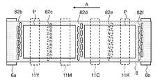
- FIG. 4 is a plan view schematically showing the positional relationship between the opening group of the first conveying belt, the drive roller, and the line head in the printer of the first embodiment, showing a state in which the first opening group is caught by the drive roller;
- FIG. 8 is a diagram showing a state in which the first conveyor belt rotates by a predetermined amount from the state of FIG. 7 and the second opening portion group is caught by the drive roller;
- FIG. 9 is a diagram showing a state in which the first conveying belt rotates by a predetermined amount from the state of FIG. 8 and the third opening portion group is caught by the drive roller;
- FIG. 10 is a diagram showing a state in which the first conveyor belt rotates by a predetermined amount from the state of FIG.
- FIG. 10 is a plan view schematically showing the positional relationship between the group of openings of the first conveyor belt, the drive roller, and the line head in the printer of the modification of the first embodiment, in which the first group of openings overlaps the drive roller;
- a diagram showing the state FIG. 10 is a side view schematically showing the positional relationship between the opening group of the first conveyor belt, the drive roller, and the line head in the printer according to the second embodiment of the present invention, in which the first opening group is caught by the drive roller;
- Figure showing the state FIG. 12 is a diagram showing a state in which the first conveying belt rotates by a predetermined amount from the state of FIG. 12 and the first opening group is separated from the drive roller;
- FIG. 10 is a plan view schematically showing the positional relationship between the opening group of the first transport belt, the drive roller, and the line head in the printer of the second embodiment, and conveys the small-sized paper by adsorbing it to the first transport belt;
- Top view showing how to FIG. 10 is a plan view schematically showing the positional relationship between the group of openings of the first transport belt, the drive roller, and the line head in the printer of the second embodiment, and transports large-sized paper by adsorbing it to the first transport belt;
- Top view showing how to FIG. 10 is a side view schematically showing the positional relationship between the opening group of the first conveyor belt, the driving roller, and the line head in the printer according to the third embodiment of the present invention, wherein the first opening group is caught by the driving roller;
- FIG. 1 is an explanatory diagram showing a schematic configuration of a printer 100 as an inkjet recording apparatus according to one embodiment of the invention.
- the printer 100 includes a paper feed cassette 2 that is a paper storage unit.
- the paper feed cassette 2 is arranged in the lower part of the printer main body 1 .
- Paper P which is an example of a recording medium, is accommodated inside the paper feed cassette 2 .
- a paper feeder 3 is arranged on the downstream side of the paper feed cassette 2 in the paper transport direction, that is, above the right side of the paper feed cassette 2 in FIG.
- the paper feeder 3 separates and feeds the paper P one by one toward the upper right side of the paper feed cassette 2 in FIG.
- the printer 100 has a first paper transport path 4a inside.
- the first paper transport path 4a is positioned on the upper right side of the paper feed cassette 2 in the paper feed direction.
- the paper P sent out from the paper feed cassette 2 is transported vertically upward along the side surface of the printer body 1 by the first paper transport path 4a.
- a registration roller pair 13 is provided at the downstream end of the first paper transport path 4a in the paper transport direction. Furthermore, the first conveying unit 5 and the recording section 9 are arranged immediately downstream of the registration roller pair 13 in the sheet conveying direction.
- the paper P sent out from the paper feed cassette 2 reaches the registration roller pair 13 through the first paper transport path 4a.
- the pair of registration rollers 13 corrects skewed feeding of the paper P, measures the timing with the ink ejection operation executed by the recording unit 9, and directs the paper toward the first conveying unit 5 (especially the first conveying belt 8 described later). Send out P.
- the paper P delivered to the first transport unit 5 by the registration roller pair 13 is transported by the first transport belt 8 to a position facing the recording unit 9 (especially recording heads 17a to 17c, which will be described later).
- An image is recorded on the paper P by ejecting ink onto the paper P from the recording unit 9 .
- ejection of ink in the recording unit 9 is controlled by the control device 110 inside the printer 100 .
- a second transport unit 12 is arranged downstream of the first transport unit 5 (left side in FIG. 1) in the paper transport direction.
- the paper P on which the image is recorded by the recording section 9 is sent to the second transport unit 12 .
- the ink ejected onto the surface of the paper P is dried while passing through the second transport unit 12 .
- a decurler section 14 is provided in the vicinity of the left side of the printer main body 1 on the downstream side of the second transport unit 12 in the paper transport direction.
- the paper P the ink of which has been dried by the second transport unit 12, is sent to the decurler section 14, where the curl of the paper P is corrected.
- a second paper transport path 4b is provided downstream of the decurler section 14 (upper in FIG. 1) in the paper transport direction.
- the paper P that has passed through the decurler section 14 passes through the second paper transport path 4b and is discharged to a paper discharge tray 15a provided outside the left side of the printer 100 when double-sided recording is not performed.
- a sub-ejection tray 15b is provided below the paper ejection tray 15a for ejecting unnecessary paper P (waste paper) having printing defects or the like.
- a reversing transport path 16 for performing double-sided recording is provided at the top of the printer main body 1 and above the recording section 9 and the second transport unit 12.
- the paper P that has completed recording on one side (first side) of the paper P and has passed through the second conveying unit 12 and the decurler section 14 passes through the second paper conveying path 4b and is reversed. It is sent to the transport path 16 .
- the conveying direction of the paper P sent to the reverse conveying path 16 is switched so that the other surface (second surface) of the paper P is subsequently recorded. Then, the paper P passes through the upper portion of the printer main body 1, is sent rightward, passes through the pair of registration rollers 13, and is sent again to the first transport unit 5 with the second surface facing upward. In the first transport unit 5 , the paper P is transported to a position facing the recording section 9 , and an image is recorded on the second surface by ink ejection from the recording section 9 . After double-sided recording, the paper P passes through the second transport unit 12, the decurler section 14, and the second paper transport path 4b in order, and is discharged to the paper discharge tray 15a.
- a maintenance unit 19 and a cap unit 20 are arranged below the second transport unit 12 .
- the maintenance unit 19 moves horizontally below the recording section 9 when purging is performed, wipes off the ink ejected from the ink ejection ports 18 (see FIG. 2) of the recording heads 17a to 17c, and wipes off the wiped ink. to recover.
- purging is an operation of forcibly pushing out ink from the ink ejection openings 18 of the recording heads 17a to 17c in order to discharge thickened ink, foreign matter, and air bubbles in the ink ejection openings 18.
- the cap unit 20 moves horizontally below the recording section 9 when capping the ink ejection surfaces of the recording heads 17a to 17c, and further moves upward to be attached to the lower surfaces of the recording heads 17a to 17c.
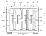
- FIG. 2 is a plan view of the recording unit 9.
- the recording unit 9 includes a head housing 10 and line heads 11Y, 11M, 11C, and 11K.
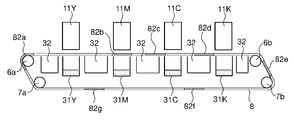
- the line heads 11Y to 11K are arranged on a conveying surface of an endless first conveying belt 8 stretched over a plurality of rollers including a driving roller 6a, a driven roller 6b, and tension rollers 7a and 7b (see FIG. 3). It is held in the head housing 10 at a height that forms a predetermined interval (for example, 1 mm).
- the drive roller 6a causes the first transport belt 8 to run in the transport direction of the paper P (arrow A direction).
- the driving of the drive roller 6a is controlled by a main control section 110a (see FIG. 4) of the control device 110.
- the plurality of rollers are arranged in the order of the tension roller 7a, the tension roller 7b, the driven roller 6b, and the drive roller 6a along the running direction of the first transport belt 8 (see FIG. 3).
- the line heads 11Y to 11K each have a plurality (here, three) of recording heads 17a to 17c.
- the recording heads 17a to 17c are arranged in a zigzag pattern along the paper width direction (arrow BB' direction) perpendicular to the paper transport direction (arrow A direction).
- the recording heads 17a to 17c have a plurality of ink ejection openings 18 (nozzles).
- the ink discharge ports 18 are arranged at regular intervals in the width direction of the recording head, that is, in the paper width direction (arrow BB' direction).
- FIG. 3 schematically shows the configuration around the transport path of the paper P from the paper feed cassette 2 to the second transport unit 12 via the first transport unit 5 .
- FIG. 4 is a block diagram showing the hardware configuration of main parts of the printer 100. As shown in FIG. Printer 100 further includes registration sensor 21 , first paper sensor 22 , second paper sensor 23 , and belt sensors 24 and 25 in addition to the above configuration.
- the registration sensor 21 detects the paper P transported from the paper cassette 2 by the paper feeding device 3 and sent to the registration roller pair 13 .
- the registration sensor 21 is located upstream of the pair of registration rollers 13 in the paper P supply direction.
- the control device 110 (for example, the paper supply control section 110 c ) controls the rotation start timing of the registration roller pair 13 based on the detection result of the registration sensor 21 . For example, based on the detection result of the registration sensor 21 , the control device 110 controls the timing of supplying the sheet P after skew correction by the registration roller pair 13 to the first conveyor belt 8 .
- the first paper sensor 22 detects the widthwise position of the paper P sent from the registration roller pair 13 to the first conveyor belt 8 .
- the control device 110 (for example, the main control unit 110a) selects the width of the paper P among the ink ejection openings 18 of the recording heads 17a to 17c of the line heads 11Y to 11K based on the detection result of the first paper sensor 22. An image can be recorded on the paper P by ejecting ink from the ink ejection port 18 .
- the second paper sensor 23 detects passage of the paper P supplied to the first conveyor belt 8 by the registration roller pair 13 . That is, the second paper sensor 23 detects the position of the paper P transported by the first transport belt 8 in the transport direction.
- the second paper sensor 23 is located upstream of the recording unit 9 and downstream of the first paper sensor 22 in the paper transport direction.
- the control device 110 controls, based on the detection result of the second paper sensor 23, the paper that reaches the position facing the line heads 11Y to 11K (recording heads 17a to 17c) by the first conveyor belt 8. Ink ejection timing for P can be controlled.
- the belt sensors 24 and 25 are reference detection sensors that detect the reference specifying portion Mref (see FIG. 5) provided on the first conveying belt 8 .
- the reference specifying portion Mref is a portion that indicates a reference for one rotation of the first conveying belt 8, and is configured by a combination of two adjacent opening portion groups 82 as described later.
- the belt sensors 24 and 25 detect the reference specific portion Mref of the first conveying belt 8 to detect Based on the position of the reference specifying portion Mref, the position of each opening group 82 provided in the first conveying belt 8 in the conveying direction can be detected. Therefore, it can be said that the belt sensors 24 and 25 function as opening position detectors that detect the positions of the opening group 82 (openings 80 ) of the first conveyor belt 8 .
- Marks are formed at positions corresponding to the opening groups 82 at the ends of the first conveying belt 8 in the belt width direction, and the belt sensors 24 and 25 detect the marks, thereby The position of the corresponding opening group 82 may be detected.
- the belt sensor 24 is positioned on the upstream side in the sheet conveying direction of the driven roller 6b around which the first conveying belt 8 is stretched.
- the belt sensor 25 is positioned downstream of the recording section 9 in the paper transport direction (the running direction of the first transport belt 8).
- the belt sensors 25 (25a, 25b) are arranged at two locations between the tension rollers 7a, 7b, but may be arranged at only one location.
- the driven roller 6b is positioned upstream of the recording unit 9 in the running direction of the first conveying belt 8 .
- the belt sensor 24 also has a function equivalent to that of the second paper sensor 23 .
- the control device 110 (for example, the paper supply control unit 110c) controls the registration roller pair 13 based on the detection result of the belt sensor 24 or 25 so as to supply the paper P to the first transport belt 8 at a predetermined timing. can be controlled.
- the position of the paper P is detected by a plurality of sensors (the second paper sensor 23 and the belt sensor 24), and the reference specific portion Mref of the first conveyor belt 8 is detected by a plurality of sensors (the belt sensors 24 and 25). This makes it possible to correct errors in detected positions and detect abnormalities.
- first paper sensor 22, second paper sensor 23, belt sensors 24 and 25 may be composed of a transmissive or reflective optical sensor, a CIS sensor (contact image sensor), or the like.
- the printer 100 may be configured to include a meandering detection sensor that detects meandering of the first conveyor belt 8, and correct the meandering of the first conveyor belt 8 based on the detection result.
- the printer 100 further includes an operation panel 27 , a storage section 28 and a communication section 29 .
- the operation panel 27 is an operation unit for receiving various setting inputs.
- the user can operate the operation panel 27 to input information on the size of the paper P to be set in the paper feed cassette 2 , that is, the size of the paper P to be conveyed by the first conveying belt 8 .
- the user can also operate the operation panel 27 to input the number of sheets of paper P to be printed and to instruct the start of a print job.
- the operation panel 27 also functions as a notification device that notifies the operation status of the printer 100 (image recording and flushing, which will be described later).
- the storage unit 28 is a memory that stores the operation program of the control device 110 and various information, and includes ROM (Read Only Memory), RAM (Random Access Memory), nonvolatile memory, and the like. There is Information set by the operation panel 27 (for example, information on the size of the paper P and the number of sheets) is stored in the storage unit 28 .
- the communication unit 29 is a communication interface for transmitting and receiving information with an external device (for example, a personal computer (PC)).
- an external device for example, a personal computer (PC)
- PC personal computer
- the image data and print command are input to the printer 100 via the communication unit 29 .
- an image can be recorded on the paper P by controlling the recording heads 17a to 17c to eject ink based on the image data by the main controller 110a.
- the printer 100 of this embodiment also includes a control device 110 .
- the control device 110 includes, for example, a CPU (Central Processing Unit) and memory.
- the control device 110 has a main control section 110a, a flushing control section 110b, a paper supply control section 110c, and a maintenance control section 110d.
- Each control unit constituting the control device 110 is composed of one CPU, but may of course be composed of separate CPUs.
- the main control unit 110 a controls the operation of each unit of the printer 100 .
- the driving of each roller inside the printer 100, the ejection of ink from the recording heads 17a to 17c during image formation (except during flushing), and the like are controlled by the main controller 110a.
- the flushing control unit 110b causes the recording heads 17a to 17c to perform flushing based on the position detection of the openings 80 (opening group 82) by the belt sensor 24 or 25. FIG. Details of flushing based on position detection of the opening 80 will be described later.
- the paper supply control unit 110c is a recording medium supply control unit that controls the registration roller pair 13 as a recording medium supply unit.
- the paper supply control unit 110c controls the registration roller pair 13 based on the detection of the position of the opening 80 by the belt sensor 24 or 25.
- FIG. The paper supply control unit 110c can also control the registration roller pair 13 independently of the position detection of the opening 80 by the belt sensor 24 or 25 (regardless of the position detection).
- the maintenance control unit 110d controls the recording heads 17a to 17c to perform the above-described purging of forcibly pushing out the ink from the respective ink ejection ports .
- the maintenance control section 110d also controls driving of the maintenance unit 19 (for example, downward movement and withdrawal of the recording section 9) when the recording heads 17a to 17c are purged.
- the printer 100 has ink receivers 31Y, 31M, 31C, and 31K on the inner peripheral surface side of the first conveyor belt 8 .
- the ink receivers 31Y to 31K receive and collect the ink ejected from the recording heads 17a to 17c and passing through the opening 80 of the first conveying belt 8 when the recording heads 17a to 17c are flushed. Therefore, the ink receivers 31Y to 31K are provided at positions facing the recording heads 17a to 17c of the line heads 11Y to 11K with the first transport belt 8 interposed therebetween.
- the ink collected by the ink receivers 31Y to 31K is sent to, for example, a waste ink tank (not shown) via an ink discharge channel (not shown) and discarded.
- the second transport unit 12 has a second transport belt 12a and a dryer 12b.
- the second transport belt 12a is stretched by two drive rollers 12c and driven rollers 12d.
- the paper P transported by the first transport unit 5 and having an image recorded thereon by ink ejection from the recording unit 9 is transported by the second transport belt 12a, dried by the dryer 12b during transport, and sent to the decurler unit 14 described above. be transported.
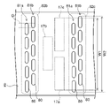
- FIG. 5 is a plan view showing a configuration example of the first conveyor belt 8 used in the printer 100 according to the first embodiment of the invention.
- FIG. 6 is a partially enlarged view around the second opening group 82b and the third opening group 82c of the first conveyor belt 8 in FIG.
- a negative pressure suction method is adopted in which the paper P is attracted to the first conveying belt 8 by negative pressure suction and conveyed. Therefore, the entire area of the first transport belt 8 is formed with a large number of suction holes 8a through which a suction air for attracting the paper P to the first transport belt 8 by negative pressure suction passes.
- the first conveying belt 8 has a plurality of openings 80 through which ink ejected from the nozzles (ink ejection ports 18) of the recording heads 17a to 17c during flushing passes.
- Each opening 80 is formed as an elongated hole in the width direction of the first conveying belt 8 (direction of arrow BB', hereinafter simply referred to as the width direction).
- the shape of each opening 80 in plan view is a shape in which regions corresponding to rectangular corners are rounded as shown in FIG. (for example, an elliptical shape).
- the groups 82g are arranged at seven locations at predetermined intervals along the conveying direction within one period S of the first conveying belt 8. As shown in FIG.
- Each aperture group 82a-82g is composed of two rows of apertures 81a and 81b.
- the opening groups 82a to 82g are not spaced the same in the transport direction, and are irregularly formed at positions corresponding to the size of the paper P to be transported.
- the intervals between adjacent opening groups 82 are not constant but different.
- the maximum distance between the two opening groups 82 adjacent to each other in the transport direction is the same as when the paper P of the minimum printable size (for example, A4 size landscape) is placed on the first transport belt 8. It is longer than the length of P in the transport direction.
- the gaps between those adjacent to each other in the conveying direction there are gaps larger than the gap between the opening row 81a and the opening row 81b. there is at least one. That is, among the predetermined intervals in the conveying direction at which the first opening group 82a to the seventh opening group 82g are arranged, there are those that are larger than the interval between the opening row 81a and the opening row 81b. there is at least one.
- each opening row 81a and 81b a plurality of (here, five) openings 80 are arranged at equal intervals in the width direction.
- Each opening 80 in one row of openings 81a partially overlaps each opening 80 in the other row of openings 81b in the belt width direction (ends in the longitudinal direction) (overlapping portion D ) are arranged such that That is, in the first conveyor belt 8, the plurality of openings 80 forming each opening group 82 are arranged in a zigzag pattern.
- the number of openings 80 in one row of openings 81a may be different from the number of openings 80 in the other row of openings 81b.
- the width W2 (mm) of the opening group 82 in the belt width direction is larger than W1.
- the recording heads 17a to 17c execute flushing, the ink discharged from each ink discharge port 18 of the recording heads 17a to 17c is discharged from each opening 80 of the opening row 81a or each opening of the opening row 81b. pass through any of the sections 80; Therefore, it is possible to perform flushing over the entire head width of the recording heads 17a to 17c and reduce clogging of all the ink discharge ports 18 due to drying of the ink.
- the control device 110 sets the pattern (combination) of the sheet transport direction of the plurality of opening groups 82 used for flushing in one period S of the first transport belt 8 to: It is determined according to the size of the paper P to be used. More specifically, the belt sensor 24 or 25 reads the reference specific portion Mref of the first conveying belt 8, and based on the position information of the reference specific portion Mref and the size information of the sheet P, the registration roller pair 13 moves the first conveying belt. 8, the first opening group 82a to the seventh opening group 82g are controlled to be positioned between the continuously conveyed sheets P at regular intervals. be.
- the size of the paper P to be used can be recognized by the control device 110 based on the information stored in the storage unit 28 (for example, the size information of the paper P input from the operation panel 27).
- the timing of flushing is not limited to the "paper interval". For example, it is possible to perform flushing before forming an image on the first sheet P or after forming an image on the last sheet P.
- FIG. 7 to 10 are plan views schematically showing the positional relationship between the opening groups 82a to 82g of the first conveying belt 8 and the drive roller 6a in the printer 100 of the first embodiment.
- FIG. 7 shows a state in which the first opening group 82a is caught by the driving roller 6a.
- the strength of the first conveying belt 8 is reduced in the regions where the groups of openings 82a to 82g are formed. Therefore, in the state of FIG. 7 in which the first opening group 82a is hooked on the driving roller 6a, the stretch of the first conveying belt is greater than that in the state in which the regions in which the opening groups 82a to 82g are not formed are hooked on the driving roller 6a. increase in quantity. As a result, the rotation speed of the first conveyor belt 8 slightly decreases.
- the second opening group 82b is positioned directly below the line head 11M. That is, when the paper P does not overlap the second opening group 82b, the line head 11M does not perform printing, but performs flushing. Then, when the first opening group 82a passes the drive roller 6a due to the rotation of the first conveying belt 8, the second opening group 82b also moves from directly below the line head 11M, and the paper P is printed. Therefore, in the line head 11M, printing can be performed without being affected by the change in the stretch amount of the first conveying belt 8 when the first opening group 82a is caught by the drive roller 6a.
- FIG. 8 is a diagram showing a state in which the first conveying belt 8 has rotated a predetermined amount from the state of FIG. 7 and the second opening group 82b is caught on the driving roller 6a.
- the fifth opening group 82e is positioned directly below the line head 11C. That is, when the paper P does not overlap the fifth opening group 82e, the line head 11C does not perform printing, but performs flushing.
- the second opening group 82b passes the drive roller 6a due to the rotation of the first conveying belt 8
- the fifth opening group 82e also moves from directly below the line head 11C, and the paper P is printed. Therefore, in the line head 11C, printing can be performed without being affected by the change in the stretch amount of the first conveying belt 8 when the second opening group 82b is caught by the driving roller 6a.
- FIG. 9 is a diagram showing a state in which the first conveying belt 8 has rotated a predetermined amount from the state of FIG. 8 and the third opening group 82c is caught by the drive roller.
- FIG. 10 is a diagram showing a state in which the first conveying belt 8 has rotated a predetermined amount from the state shown in FIG. 9 and the seventh opening group 82g is caught by the drive roller.
- the fourth opening group 82d is positioned directly below the line head 11Y.
- the first opening group 82a is positioned directly below the line head 11Y.
- the fourth opening group 82d and the first opening group 82a are also directly below the line head 11Y. , and printing is performed on the paper P. Therefore, in the line head 11Y, printing can be performed without being affected by changes in the amount of elongation of the first conveying belt 8 when the third opening group 82c and the seventh opening group 82g are caught by the driving roller 6a. can be done.
- an aperture pair 83 a pair of aperture groups positioned directly below the heads 11Y to 11K.
- none of the opening groups 82c to 82g are positioned directly below the line heads 11Y, 11C, and 11K. That is, the line heads 11Y, 11C, and 11K are affected by changes in the amount of elongation of the first conveying belt 8 when the first opening group 82a is caught by the drive roller 6a. Similarly, in FIGS. 8 to 10, the line heads 11Y to 11K in which none of the opening groups 82c to 82g are positioned are affected by changes in the stretch amount of the first conveyor belt 8. FIG.
- the group of openings 82a to 82g overlap the drive roller 6a, and the first conveying belt 8 It is possible to suppress the deterioration of image quality by reducing the influence of the change in the amount of elongation on printing.
- the number (proportion) of the opening groups 82a to 82g forming the opening pair 83 is large among all the opening groups 82a to 82g.
- the ratio of the number of the opening groups 82a to 82g forming the opening pair 83 to the total number of the opening groups 82a to 82g is preferably 1/4 or more, more preferably 1/2 or more.
- six of the opening groups 82a to 82g other than the sixth opening group 82f constitute the opening pair 83.
- the ratio of the number (six) of the opening groups 82a to 82g forming the portion pair 83 is 6/7.
- any of the opening groups 82a to 82g is engaged with the driving roller 6a, it is preferable that any one of the opening groups 82a to 82g is always positioned directly below at least one line head 11Y to 11K.
- FIG. 11 is a plan view schematically showing the positional relationship between each opening group 82a to 82g of the first conveyor belt 8 and the drive roller 6a in the printer 100 of the modification of the first embodiment.
- the arrangement pattern of the group of openings 82a to 82g formed in the first conveying belt 8 is different.
- a second opening group 82b is positioned immediately below the .
- a fourth opening group 82d is positioned directly below the line head 11K.
- an opening group 85 a combination of the opening groups 82a to 82g located directly below the line heads 11Y to 11K at the same time.
- the opening group 85 it is preferable that the number (proportion) of the opening groups 82a to 82g forming the opening group 85 is large among all the opening groups 82a to 82g.
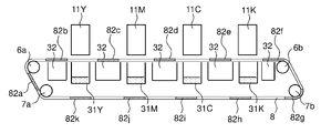
- FIG. 12 is a side view schematically showing the positional relationship between each opening group 82a to 82k of the first conveyor belt 8 and the driving roller 6a in the printer 100 according to the second embodiment of the invention.
- the first conveying belt 8 is provided with a total of eleven first opening group 82a to eleventh opening group 82k (hatched areas in the figure) at equal intervals along the conveying direction. Also, the intervals between the respective opening groups 82a-82k are equal to the arrangement intervals of the adjacent line heads 11Y-11K. Further, the intervals between the opening groups 82a to 82k are equal to the distance from the most downstream line head 11Y in the transport direction to the drive roller 6a.
- FIG. 13 is a diagram showing a state in which the first conveying belt 8 has rotated a predetermined amount from the state shown in FIG. 12, and the first opening group 82a is separated from the drive roller 6a.
- the second opening group 82b to the fifth opening group 82e also move from directly below the line heads 11Y to 11K.
- the first conveying belt 8 rotates further and the second opening group 82b is caught on the driving roller 6a, the following four opening groups 82c to 82c to sixth opening groups are directly below the line heads 11Y to 11K. 82f is placed.
- the openings of the first opening group 82a to the eleventh opening group 82k are directly below the line heads 11Y to 11K. , four following the group of openings 82c to 82k hanging over the driving roller 6a.
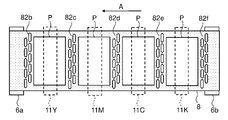
- FIG. 14 is a plan view schematically showing the positional relationship between the group of openings 82a to 82k of the first conveyor belt 8, the drive roller 6a, and the line heads 11Y to 11K in the printer 100 of the second embodiment.
- 1 is a plan view showing how a small-sized sheet P is attracted to and conveyed by a conveying belt 8.
- small-sized (for example, A4 horizontal size) paper P is arranged between the opening groups 82a to 82k.
- the following four opening groups are always positioned directly below each of the line heads 11Y to 11K. Therefore, printing on the paper P is not performed, and flushing is performed.
- FIG. 15 is a plan view showing how the first transport belt 8 adsorbs and transports the large-sized paper P.
- a large size (for example, A3 size) paper P is arranged across any one of the opening groups 82a to 82k (here, the third opening group 82c and the fifth opening group 82e). . Therefore, printing is executed even when any one of the opening groups 82a to 82k is over the driving roller 6a and the third opening group 82c and the fifth opening group 82e are directly below the line heads 11Y to 11K. There is a need to.
- the intervals between the groups of openings 82a to 82k are made larger than the size of the paper P most frequently used. is preferred.
- the interval between the groups of openings 82a to 82k is equal to the distance from the line head 11Y on the most downstream side in the transport direction to the drive roller 6a.
- the distance may be an integral multiple of the interval between the opening groups 82a-82k.
- FIG. 16 is a side view schematically showing the positional relationship between each opening group 82a to 82k of the first conveyor belt 8 and the drive roller 6a in the printer 100 according to the third embodiment of the invention.
- the arrangement pattern of the opening groups 82a to 82g formed in the first conveying belt 8 is the same as in the first embodiment.
- rollers in contact with the first conveyor belt 8 will be summarized.
- rollers other than the drive roller 6a which change the moving direction of the first transport belt 8 by 30 degrees or more, are called tension rollers.
- the tension roller 7a, the tension roller 7b and the driven roller 6b are tension rollers.
- one plane of the first conveyor belt 8 facing the recording heads 17a to 17c is called a mounting plane.
- the rollers arranged at the upstream end and the downstream end of the mounting plane in the transport direction are called transport end rollers.
- the driven roller 6b is a tension roller arranged at the upstream end of the mounting plane in the transport direction, and is a transport end roller.
- the drive roller 6a is a roller arranged at the downstream end of the mounting plane in the transport direction, but it is not a tension roller and therefore not a transport end roller. If a roller that is not driven from the outside is arranged at the position of the drive roller 6a, that roller becomes the transport end roller.
- all the other opening groups 82a to 82g are in contact with the driving roller 6a, and all the other opening groups 82a to 82g are tension rollers (driven roller 6b, tension roller 7a). , 7b).
- one group of openings 82a to 82g (here, first group of openings 82a) is in contact with drive roller 6a
- another group of openings here, there is a group of openings such that the group of openings 82b to 82g) does not overlap the tension rollers (driven roller 6b, tension rollers 7a and 7b).
- the first conveying belt 8 stretches. quantity increases. Therefore, if printing is executed in this state, the change in the amount of elongation will have a large effect.
- the first conveying belt when printing is executed in a state where the specific opening group is hung on the driving roller 6a.
- the influence of the elongation amount of 8 can be minimized.
- the greater the number (proportion) of the specific opening groups among all the opening groups 82a to 82g the more the effect of the change in the elongation amount of the first conveying belt 8 can be reduced.
- any one of the opening groups 82a to 82k is positioned directly below all the line heads 11Y to 11K when any one of the opening groups 82a to 82k is engaged with the driving roller 6a. Even if there is, it is effective to combine it with the present embodiment when arranging the large size paper P so as to straddle the opening groups 82a to 82k as shown in FIG.
- the present invention is not limited to the above embodiments, and various modifications can be made without departing from the scope of the present invention.
- the paper P is attracted to the first conveyor belt 8 by negative pressure suction using the suction unit 32 and conveyed. It may be conveyed by being electrostatically attracted to the first conveying belt 8 (electrostatic attraction method).
- the present invention can be used for inkjet recording devices such as inkjet printers.
Landscapes
- Ink Jet (AREA)
Abstract
Description
以下、図面を参照しながら本発明の実施形態について説明する。図1は、本発明の一実施形態に係るインクジェット記録装置としてのプリンター100の概略の構成を示す説明図である。プリンター100は、用紙収容部である給紙カセット2を備えている。給紙カセット2は、プリンター本体1の内部下方に配置されている。給紙カセット2の内部には、記録媒体の一例である用紙Pが収容されている。
次に、第1搬送ユニット5の第1搬送ベルト8の詳細について説明する。図5は、本発明の第1実施形態に係るプリンター100に用いられる第1搬送ベルト8の一構成例を示す平面図である。図6は、図5における第1搬送ベルト8の第2開口部群82b、第3開口部群82c周辺の部分拡大図である。
次に、第1実施形態のプリンター100における第1ベルト搬送部5の構成について説明する。図7~図10は、第1実施形態のプリンター100における第1搬送ベルト8の各開口部群82a~82gと駆動ローラー6aとの位置関係を模式的に示す平面図である。
次に、本発明の第2実施形態のプリンター100における第1ベルト搬送部5の構成について説明する。図12は、本発明の第2実施形態に係るプリンター100における第1搬送ベルト8の各開口部群82a~82kと駆動ローラー6aとの位置関係を模式的に示す側面図である。
次に、本発明の第3実施形態のプリンター100における第1ベルト搬送部5の構成について説明する。図16は、本発明の第3実施形態に係るプリンター100における第1搬送ベルト8の各開口部群82a~82kと駆動ローラー6aとの位置関係を模式的に示す側面図である。第1搬送ベルト8に形成される開口部群82a~82gの配置パターンは第1実施形態と同様である。
本発明は、上記各実施形態に限定されず、本発明の趣旨を逸脱しない範囲で種々の変更が可能である。例えば、上記各実施形態では、吸引部32を用いた負圧吸引によって用紙Pを第1搬送ベルト8に吸着させて搬送する場合について説明したが、第1搬送ベルト8を帯電させ、用紙Pを第1搬送ベルト8に静電吸着させて搬送するようにしてもよい(静電吸着方式)。
Claims (11)
- インクを吐出する複数のノズルを有する記録ヘッドを少なくとも一つ有するラインヘッドと、
複数の開口部を有し、記録媒体を担持して搬送する無端状の搬送ベルトと、
前記記録媒体の搬送方向に対し前記搬送ベルトの下流側において前記搬送ベルトの内周面に接触し、前記搬送ベルトを回転駆動する駆動ローラーと、
前記駆動ローラーと共に前記搬送ベルトを張架する1つ以上の張架ローラーと、
前記記録ヘッドおよび前記搬送ベルトの駆動を制御して、画像記録に寄与するタイミングとは異なるタイミングで前記記録ヘッドの前記ノズルから前記インクを吐出させて複数の前記開口部のいずれかを通過させるフラッシングを実行する制御部と、
を備えたインクジェット記録装置において、
前記搬送ベルトには、前記搬送ベルトの幅方向および前記搬送方向に並ぶ複数の前記開口部で構成される開口部群が、前記搬送方向の複数箇所に所定の間隔を隔てて形成されており、
複数の前記開口部群のいずれか一つが前記駆動ローラーに接触している状態で、他の前記開口部群の少なくとも一つが前記ラインヘッドの直下に位置していることを特徴とするインクジェット記録装置。 - 前記駆動ローラーに接触している前記開口部群と、前記ラインヘッドの直下に位置している前記開口部群との対を開口部対とするとき、
全ての前記開口部群の個数に対する、前記開口部対を構成する前記開口部群の個数の割合が1/4以上であることを特徴とする請求項1に記載のインクジェット記録装置。 - 複数の前記開口部群の全てが前記開口部対を構成することを特徴とする請求項2に記載のインクジェット記録装置。
- 複数の前記開口部群のいずれか一つが前記駆動ローラーに接触している状態で、常に前記ラインヘッドの直下に他の前記開口部群が位置していることを特徴とする請求項3に記載のインクジェット記録装置。
- 前記ラインヘッドが前記搬送方向に複数配置されており、
前記駆動ローラーに接触している前記開口部群と、複数の前記ラインヘッドの直下に同時に位置している複数の前記開口部群との組み合わせである開口部組が少なくとも一つ存在することを特徴とする請求項1に記載のインクジェット記録装置。 - 複数の前記開口部群のいずれか一つが前記駆動ローラーに接触している状態で、常に全ての前記ラインヘッドの直下に前記開口部群が位置していることを特徴とする請求項5に記載のインクジェット記録装置。
- 前記搬送ベルトは、複数の前記開口部群が等間隔で形成されており、
前記開口部群の間隔は、隣接する前記ラインヘッドの配置間隔と等しく、前記搬送方向に対し最下流側に位置する前記ラインヘッドと前記駆動ローラーとの間隔は、前記開口部群の間隔の整数倍であることを特徴とする請求項6に記載のインクジェット記録装置。 - 前記張架ローラーのうち、前記記録ヘッドと対向する前記搬送ベルトの載置平面の前記搬送方向の上流端および下流端に配置されたローラーを搬送端ローラーとするとき、
複数の前記開口部群のうち少なくとも一つは、前記駆動ローラーに接触している状態で、他の全ての前記開口部群が前記搬送端ローラーに接触しない位置関係となる特定開口部群であることを特徴とする請求項1に記載のインクジェット記録装置。 - インクを吐出する複数のノズルを有する記録ヘッドを少なくとも一つ有するラインヘッドと、
複数の開口部を有し、記録媒体を担持して搬送する無端状の搬送ベルトと、
前記記録媒体の搬送方向に対し前記搬送ベルトの下流側において前記搬送ベルトの内周面に接触し、前記搬送ベルトを回転駆動する駆動ローラーと、
前記駆動ローラーと共に前記搬送ベルトを張架する1つ以上の張架ローラーと、
前記記録ヘッドおよび前記搬送ベルトの駆動を制御して、画像記録に寄与するタイミングとは異なるタイミングで前記記録ヘッドの前記ノズルから前記インクを吐出させて複数の前記開口部のいずれかを通過させるフラッシングを実行する制御部と、
を備えたインクジェット記録装置において、
前記張架ローラーのうち、前記記録ヘッドと対向する前記搬送ベルトの載置平面の前記搬送方向の上流端および下流端に配置されたローラーを搬送端ローラーとするとき、
複数の前記開口部群のうち少なくとも一つは、前記駆動ローラーに接触している状態で、他の全ての前記開口部群が前記搬送端ローラーに接触しない位置関係となる特定開口部群であることを特徴とするインクジェット記録装置。 - 前記特定開口部群は、複数の前記開口部群のうち、前記駆動ローラーに接触している状態で、他の全ての前記開口部群が前記張架ローラーに接触しない位置関係となる開口部群であることを特徴とする請求項9に記載のインクジェット記録装置。
- 複数の前記開口部群の全てが前記特定開口部群であることを特徴とする請求項9に記載のインクジェット記録装置。
Priority Applications (3)
| Application Number | Priority Date | Filing Date | Title |
|---|---|---|---|
| CN202280020893.9A CN116963908A (zh) | 2021-03-15 | 2022-03-09 | 喷墨记录装置 |
| JP2023507020A JP7677400B2 (ja) | 2021-03-15 | 2022-03-09 | インクジェット記録装置 |
| US18/550,103 US12528296B2 (en) | 2021-03-15 | 2022-03-09 | Inkjet recording apparatus capable of suppressing an influence of a change in belt speed during image recording |
Applications Claiming Priority (2)
| Application Number | Priority Date | Filing Date | Title |
|---|---|---|---|
| JP2021041017 | 2021-03-15 | ||
| JP2021-041017 | 2021-03-15 |
Publications (1)
| Publication Number | Publication Date |
|---|---|
| WO2022196483A1 true WO2022196483A1 (ja) | 2022-09-22 |
Family
ID=83320568
Family Applications (1)
| Application Number | Title | Priority Date | Filing Date |
|---|---|---|---|
| PCT/JP2022/010246 Ceased WO2022196483A1 (ja) | 2021-03-15 | 2022-03-09 | インクジェット記録装置 |
Country Status (4)
| Country | Link |
|---|---|
| US (1) | US12528296B2 (ja) |
| JP (1) | JP7677400B2 (ja) |
| CN (1) | CN116963908A (ja) |
| WO (1) | WO2022196483A1 (ja) |
Citations (6)
| Publication number | Priority date | Publication date | Assignee | Title |
|---|---|---|---|---|
| US4207578A (en) * | 1979-01-08 | 1980-06-10 | The Mead Corporation | Catch trough for a jet drop recorder |
| JP2005081591A (ja) * | 2003-09-05 | 2005-03-31 | Fuji Xerox Co Ltd | 記録装置 |
| JP2005205901A (ja) * | 2003-12-25 | 2005-08-04 | Fuji Photo Film Co Ltd | 画像形成装置 |
| JP2006069135A (ja) * | 2004-09-06 | 2006-03-16 | Seiko Epson Corp | インクジェット記録装置 |
| WO2021070856A1 (ja) * | 2019-10-11 | 2021-04-15 | 京セラドキュメントソリューションズ株式会社 | インクジェット記録装置 |
| JP2021062533A (ja) * | 2019-10-11 | 2021-04-22 | 京セラドキュメントソリューションズ株式会社 | インクジェット記録装置 |
Family Cites Families (5)
| Publication number | Priority date | Publication date | Assignee | Title |
|---|---|---|---|---|
| US7334862B2 (en) * | 2003-12-25 | 2008-02-26 | Fujifilm Corporation | Image forming apparatus for performing restoration process |
| JP4020105B2 (ja) * | 2004-07-07 | 2007-12-12 | セイコーエプソン株式会社 | インクジェット記録装置 |
| JP4905004B2 (ja) * | 2006-09-06 | 2012-03-28 | セイコーエプソン株式会社 | インクジェットプリンタ |
| JP2008279627A (ja) * | 2007-05-09 | 2008-11-20 | Seiko Epson Corp | 印刷装置 |
| JP4305560B2 (ja) | 2008-04-17 | 2009-07-29 | セイコーエプソン株式会社 | インクジェット記録装置 |
-
2022
- 2022-03-09 JP JP2023507020A patent/JP7677400B2/ja active Active
- 2022-03-09 CN CN202280020893.9A patent/CN116963908A/zh active Pending
- 2022-03-09 US US18/550,103 patent/US12528296B2/en active Active
- 2022-03-09 WO PCT/JP2022/010246 patent/WO2022196483A1/ja not_active Ceased
Patent Citations (6)
| Publication number | Priority date | Publication date | Assignee | Title |
|---|---|---|---|---|
| US4207578A (en) * | 1979-01-08 | 1980-06-10 | The Mead Corporation | Catch trough for a jet drop recorder |
| JP2005081591A (ja) * | 2003-09-05 | 2005-03-31 | Fuji Xerox Co Ltd | 記録装置 |
| JP2005205901A (ja) * | 2003-12-25 | 2005-08-04 | Fuji Photo Film Co Ltd | 画像形成装置 |
| JP2006069135A (ja) * | 2004-09-06 | 2006-03-16 | Seiko Epson Corp | インクジェット記録装置 |
| WO2021070856A1 (ja) * | 2019-10-11 | 2021-04-15 | 京セラドキュメントソリューションズ株式会社 | インクジェット記録装置 |
| JP2021062533A (ja) * | 2019-10-11 | 2021-04-22 | 京セラドキュメントソリューションズ株式会社 | インクジェット記録装置 |
Also Published As
| Publication number | Publication date |
|---|---|
| US12528296B2 (en) | 2026-01-20 |
| JPWO2022196483A1 (ja) | 2022-09-22 |
| CN116963908A (zh) | 2023-10-27 |
| US20240149586A1 (en) | 2024-05-09 |
| JP7677400B2 (ja) | 2025-05-15 |
Similar Documents
| Publication | Publication Date | Title |
|---|---|---|
| US11390084B2 (en) | Inkjet recording apparatus for recording images by ejecting ink on recording media | |
| EP3804996B1 (en) | Inkjet recording apparatus | |
| JP2021088183A (ja) | インクジェット記録装置 | |
| US20210402809A1 (en) | Inkjet recording device | |
| JP7392420B2 (ja) | インクジェット記録装置 | |
| JP7459637B2 (ja) | インクジェット記録装置 | |
| JP7380871B2 (ja) | 記録装置のベルトおよび記録装置 | |
| JP7559577B2 (ja) | インクジェット記録装置 | |
| JP7494518B2 (ja) | インクジェット記録装置 | |
| JP2022152081A (ja) | インクジェット記録装置 | |
| JP2022014483A (ja) | インクジェット記録装置 | |
| JP7677400B2 (ja) | インクジェット記録装置 | |
| US11926159B2 (en) | Ink-jet recording apparatus | |
| JP2022129620A (ja) | インクジェット記録装置 | |
| JP7732256B2 (ja) | インクジェット記録装置 | |
| JP7484358B2 (ja) | インクジェット記録装置 | |
| JP2022148027A (ja) | インクジェット記録装置 | |
| WO2021070855A1 (ja) | インクジェット記録装置 | |
| JP2022014484A (ja) | インクジェット記録装置におけるインク吐出タイミングの調整方法 | |
| JP2021066047A (ja) | インクジェット記録装置 | |
| WO2021070856A1 (ja) | インクジェット記録装置 | |
| JP2021074984A (ja) | インクジェット記録装置 | |
| JP7494517B2 (ja) | インクジェット記録装置 | |
| JP7460969B2 (ja) | インクジェット記録装置 | |
| JP7746713B2 (ja) | インクジェット記録装置 |
Legal Events
| Date | Code | Title | Description |
|---|---|---|---|
| 121 | Ep: the epo has been informed by wipo that ep was designated in this application |
Ref document number: 22771234 Country of ref document: EP Kind code of ref document: A1 |
|
| WWE | Wipo information: entry into national phase |
Ref document number: 18550103 Country of ref document: US Ref document number: 2023507020 Country of ref document: JP |
|
| WWE | Wipo information: entry into national phase |
Ref document number: 202280020893.9 Country of ref document: CN |
|
| NENP | Non-entry into the national phase |
Ref country code: DE |
|
| 122 | Ep: pct application non-entry in european phase |
Ref document number: 22771234 Country of ref document: EP Kind code of ref document: A1 |
|
| WWG | Wipo information: grant in national office |
Ref document number: 18550103 Country of ref document: US |