WO2022196359A1 - 積層鉄心の製造方法及び積層鉄心 - Google Patents
積層鉄心の製造方法及び積層鉄心 Download PDFInfo
- Publication number
- WO2022196359A1 WO2022196359A1 PCT/JP2022/008852 JP2022008852W WO2022196359A1 WO 2022196359 A1 WO2022196359 A1 WO 2022196359A1 JP 2022008852 W JP2022008852 W JP 2022008852W WO 2022196359 A1 WO2022196359 A1 WO 2022196359A1
- Authority
- WO
- WIPO (PCT)
- Prior art keywords
- pair
- portions
- core
- crimped
- thickness direction
- Prior art date
Links
- 238000004519 manufacturing process Methods 0.000 title claims abstract description 17
- XEEYBQQBJWHFJM-UHFFFAOYSA-N Iron Chemical group [Fe] XEEYBQQBJWHFJM-UHFFFAOYSA-N 0.000 title abstract description 11
- 238000000034 method Methods 0.000 claims description 15
- 238000002788 crimping Methods 0.000 description 57
- 230000000694 effects Effects 0.000 description 10
- 229910000831 Steel Inorganic materials 0.000 description 6
- 239000010959 steel Substances 0.000 description 6
- 230000000052 comparative effect Effects 0.000 description 4
- 230000015572 biosynthetic process Effects 0.000 description 3
- 238000003825 pressing Methods 0.000 description 3
- 238000003780 insertion Methods 0.000 description 2
- 230000037431 insertion Effects 0.000 description 2
- 238000003475 lamination Methods 0.000 description 2
- 239000000463 material Substances 0.000 description 2
- 230000002093 peripheral effect Effects 0.000 description 2
- 238000004080 punching Methods 0.000 description 2
- 238000010030 laminating Methods 0.000 description 1
- 238000012986 modification Methods 0.000 description 1
- 230000004048 modification Effects 0.000 description 1
- 238000000465 moulding Methods 0.000 description 1
Images


Classifications
-
- H—ELECTRICITY
- H02—GENERATION; CONVERSION OR DISTRIBUTION OF ELECTRIC POWER
- H02K—DYNAMO-ELECTRIC MACHINES
- H02K1/00—Details of the magnetic circuit
- H02K1/06—Details of the magnetic circuit characterised by the shape, form or construction
- H02K1/22—Rotating parts of the magnetic circuit
- H02K1/27—Rotor cores with permanent magnets
- H02K1/2706—Inner rotors
- H02K1/272—Inner rotors the magnetisation axis of the magnets being perpendicular to the rotor axis
- H02K1/274—Inner rotors the magnetisation axis of the magnets being perpendicular to the rotor axis the rotor consisting of two or more circumferentially positioned magnets
- H02K1/2753—Inner rotors the magnetisation axis of the magnets being perpendicular to the rotor axis the rotor consisting of two or more circumferentially positioned magnets the rotor consisting of magnets or groups of magnets arranged with alternating polarity
- H02K1/276—Magnets embedded in the magnetic core, e.g. interior permanent magnets [IPM]
-
- B—PERFORMING OPERATIONS; TRANSPORTING
- B21—MECHANICAL METAL-WORKING WITHOUT ESSENTIALLY REMOVING MATERIAL; PUNCHING METAL
- B21D—WORKING OR PROCESSING OF SHEET METAL OR METAL TUBES, RODS OR PROFILES WITHOUT ESSENTIALLY REMOVING MATERIAL; PUNCHING METAL
- B21D28/00—Shaping by press-cutting; Perforating
- B21D28/02—Punching blanks or articles with or without obtaining scrap; Notching
-
- H—ELECTRICITY
- H02—GENERATION; CONVERSION OR DISTRIBUTION OF ELECTRIC POWER
- H02K—DYNAMO-ELECTRIC MACHINES
- H02K1/00—Details of the magnetic circuit
- H02K1/06—Details of the magnetic circuit characterised by the shape, form or construction
- H02K1/12—Stationary parts of the magnetic circuit
- H02K1/18—Means for mounting or fastening magnetic stationary parts on to, or to, the stator structures
-
- H—ELECTRICITY
- H02—GENERATION; CONVERSION OR DISTRIBUTION OF ELECTRIC POWER
- H02K—DYNAMO-ELECTRIC MACHINES
- H02K15/00—Methods or apparatus specially adapted for manufacturing, assembling, maintaining or repairing of dynamo-electric machines
- H02K15/02—Methods or apparatus specially adapted for manufacturing, assembling, maintaining or repairing of dynamo-electric machines of stator or rotor bodies
- H02K15/03—Methods or apparatus specially adapted for manufacturing, assembling, maintaining or repairing of dynamo-electric machines of stator or rotor bodies having permanent magnets
-
- H—ELECTRICITY
- H02—GENERATION; CONVERSION OR DISTRIBUTION OF ELECTRIC POWER
- H02K—DYNAMO-ELECTRIC MACHINES
- H02K2201/00—Specific aspects not provided for in the other groups of this subclass relating to the magnetic circuits
- H02K2201/09—Magnetic cores comprising laminations characterised by being fastened by caulking
Definitions
- the present disclosure relates to a laminated core and a manufacturing method thereof.
- the laminated fixed product is assembled by connecting the thin plates by engaging the crimped portions formed on the thin plates vertically by press working.
- the caulking portion is composed of a pair of left and right elastic pieces formed by punching a thin plate into a substantially V-shape when viewed from the side, and a pair of left and right openings formed in the thin plate by punching the elastic pieces.
- the crimped portion has an elongated shape whose longitudinal direction is the direction in which the pair of elastic pieces are arranged, and the ends of the pair of elastic pieces are formed in a shape curved downward.
- the pair of elastic pieces since the pair of elastic pieces has a curved shape that is likely to be elastically deformed in the longitudinal direction of the crimped portion, there is room for improvement from the viewpoint of increasing the crimping rigidity of the crimped portion in the longitudinal direction.
- the portion between the pair of elastic portions in the crimping portion is not used for crimping, there is room for improvement from the viewpoint of increasing the crimping force in the thickness direction of the thin plate.
- the pair of elastic pieces may interfere with each other in the thickness direction of the thin plates, a gap between the thin plates may occur. Therefore, there is room for improvement in terms of reducing the gap between the plates.
- the present disclosure aims to obtain a method for manufacturing a laminated core and a laminated core that can increase the crimping rigidity in the longitudinal direction of the crimped portion and the crimping force in the thickness direction of the core pieces.
- a method for manufacturing a laminated core according to a first aspect is to manufacture a laminated core by fitting long crimped portions formed in respective core pieces by press working and fixing the respective core pieces in a stacked manner.
- the crimped portion when the crimped portion is formed, it is connected to the main body portion of the core piece, is recessed with respect to the surface on one side in the thickness direction of the core piece, and is formed on the other side in the thickness direction of the core piece.
- a flat portion that is convex with respect to the surface of and parallel to each of the surfaces, and a flat portion that is opposite to each other in the longitudinal direction from both ends of the flat portion in the longitudinal direction of the crimped portion and the other side in the thickness direction and a pair of extending portions having a pair of inclined portions extending obliquely toward each other, and when forming the pair of inclined portions, the pair of inclined portions are extended in the oblique direction.
- the long crimped portions formed in the respective core pieces by press working are engaged with each other to laminate and fix the respective core pieces to manufacture the laminated core.
- a flat portion and a pair of extension portions are formed.
- the flat portion is connected to the main body portion of the core piece, is concave with respect to the surface on one side in the thickness direction of the core piece, is convex with respect to the surface on the other side in the thickness direction of the core piece, and parallel to
- the pair of extending portions has a pair of inclined portions extending obliquely from both ends of the flat portion in the longitudinal direction of the crimped portion to opposite sides in the longitudinal direction and toward the other side in the thickness direction.
- the pair of inclined portions By setting the angle of inclination of the core piece to the main body portion to be small, the pair of inclined portions can be formed into a shape that is difficult to elastically deform in the longitudinal direction of the crimped portion. Thereby, the crimping rigidity in the longitudinal direction of the crimping portion can be increased. Further, in the crimping portion, the flat portion between the pair of inclined portions is used for crimping fitting, so that the crimping force in the thickness direction of the core piece can be increased. Moreover, when forming the pair of inclined portions, the pair of inclined portions are extended in the oblique direction.
- the thickness of at least a part of the pair of inclined portions is thinner than the main body portion of the core piece, the inclined portions of the respective core pieces are less likely to interfere with each other in the thickness direction of the core pieces. As a result, the gap between the plates is reduced, so that the crimping rigidity and crimping force can be further increased.
- a laminated core according to a second aspect is a laminated core in which long crimped portions formed in respective core pieces by press working are fitted to each other and the respective core pieces are laminated and fixed to each other, wherein the crimped portions is connected to the main body portion of the core piece, is concave with respect to the surface on one side in the thickness direction of the core piece, is convex with respect to the surface on the other side in the thickness direction of the core piece, and each of the surfaces and a flat portion parallel to the crimped portion, and obliquely extending from both ends of the flat portion in the longitudinal direction of the crimped portion on the opposite side in the longitudinal direction and toward the other side in the thickness direction, at least in part and a pair of extending portions having a pair of inclined portions that are thinner than the main body portion of the core piece.
- the long crimped portions formed on the core pieces by press working are fitted to each other, and the core pieces are laminated and fixed to each other.
- the crimped portion has a flat portion and a pair of extension portions.
- the flat portion is connected to the main body portion of the core piece, is concave with respect to the surface on one side in the thickness direction of the core piece, is convex with respect to the surface on the other side in the thickness direction of the core piece, and parallel to
- the pair of extending portions has a pair of inclined portions extending obliquely from both ends of the flat portion in the longitudinal direction of the crimped portion to opposite sides in the longitudinal direction and toward the other side in the thickness direction.
- the pair of inclined portions can be formed into a shape that is difficult to elastically deform in the longitudinal direction of the crimped portion.
- the crimping rigidity in the longitudinal direction of the crimping portion can be increased.
- the flat portion between the pair of inclined portions is used for crimping fitting, so that the crimping force in the thickness direction of the core piece can be increased.
- the pair of inclined portions is at least partially thinner than the main body portion of the core piece, the inclined portions of the respective core pieces are less likely to interfere with each other in the thickness direction of the core pieces. As a result, the gap between the plates is reduced, so that the crimping rigidity and crimping force can be further increased.
- a laminated core according to a third aspect is the laminated core according to the second aspect, wherein the pair of extending portions extend from the end of the pair of inclined portions opposite to the flat portion to the sides opposite to each other in the longitudinal direction. It has a pair of outer flats extending toward and parallel to each of said faces.
- the pair of outer flat portions of the pair of extension portions of the crimped portion extend from the end of the pair of inclined portions opposite to the flat portion toward the opposite sides in the longitudinal direction. deferred. These outer flat portions increase the contact area between the caulked portions of the core pieces, so that the caulking force can be further increased.
- a laminated core according to a fourth aspect is the laminated core according to the second aspect or the third aspect, wherein, when the thickness of the core piece is 1, the recessed depth of the flat portion from the one side surface in the thickness direction is It is set within the range of 0.15 to 0.85.
- the depth by which the flat portion of the caulked portion is recessed from the surface on one side in the thickness direction of the core piece is set within the above range.
- a laminated core according to a fifth aspect is the laminated core according to any one of the second aspect to the fourth aspect, wherein the pair of extending portions has an end opposite to the flat portion that extends from the main body. directly connected to the department.
- the laminated core of the fifth aspect is configured as described above, the ends of the pair of extending portions opposite to the flat portions are directly supported by the main body portions of the core pieces. This makes it difficult for the pair of extending portions to deform unintentionally, so that the caulking force in the thickness direction of the core pieces can be increased.
- a laminated core according to a sixth aspect is the laminated core according to any one of the second aspect to the fourth aspect, wherein the pair of extension portions has the end portion opposite to the flat portion. Do not connect directly to the main unit.
- the pair of extension portions can be arranged to protrude from the surface of the core piece on the other side in the thickness direction.
- the contact area between the crimped portions in the pair of extension portions can be increased, so that the crimping force in the thickness direction of the core piece can be increased.
- a laminated core according to a seventh aspect is the laminated core according to the first aspect or the second aspect, in which a plurality of crimped portions are formed in each of the core pieces so as to be connected to each other in the longitudinal direction.
- the contact area between the crimped portions can be increased, and the crimping force in the thickness direction of the core pieces can be increased.
- a laminated core according to an eighth aspect is the laminated core according to any one aspect of the third aspect or the fourth to seventh aspects citing the third aspect, wherein the pair of extension portions comprises the The pair of outer flat portions obliquely extend from the ends of the pair of outer flat portions opposite to the pair of inclined portions toward the one side in the thickness direction on opposite sides in the longitudinal direction, and at least partially extend from the main body portion. has a pair of outer ramps with a smaller thickness.
- the pair of outer inclined portions of the pair of extension portions of the crimped portion are arranged in the longitudinal direction of the crimped portions from the end opposite to the pair of inclined portions of the pair of outer flat portions. and extends obliquely toward one side in the thickness direction of the core piece.
- These outer inclined portions can guide the caulking fitting between the caulking portions of the core pieces.
- the pair of outer inclined portions are at least partially thinner than the main body portion of the core piece, the pair of outer inclined portions are less likely to interfere with each other in the thickness direction of the core piece. As a result, the gap between the plates is less likely to occur, so that the effects of increasing the crimping rigidity and the crimping force described above are ensured.
- a laminated core according to a ninth aspect is the laminated core according to the third aspect or any one of the fourth to seventh aspects citing the third aspect, wherein each of the outer flat portions has the thickness Including those arranged at positions different from each other in the direction.
- the crimping force of the crimped portions of the outer flat portions can be made different. can be done. This improves the degree of freedom in setting the caulking force.
- the crimping rigidity in the longitudinal direction of the crimped portion and the crimping force in the thickness direction of the core pieces can be increased.
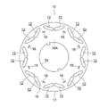
- FIG. 1 is a plan view showing the configuration of a laminated core according to a first embodiment
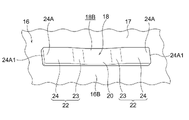
- FIG. FIG. 4 is a perspective view showing the periphery of the caulked portion of the core piece of the laminated core according to the first embodiment, viewed from one side in the thickness direction of the core piece.
- FIG. 4 is a perspective view showing the periphery of the caulked portion of the core piece of the laminated core according to the first embodiment, viewed from the other side in the thickness direction of the core piece.
- FIG. 3 is a perspective view showing a part of FIG. 2 as seen from a direction different from that of FIG. 2;
- FIG. 4 is a perspective view showing a part of FIG. 3 as viewed from a direction different from that of FIG. 3;
- FIG. 3 is a cross-sectional view showing a cut surface along line F6-F6 of FIG. 2;
- FIG. 7 is a cross-sectional view corresponding to FIG. 6 showing a state of lamination of core pieces; It is the 1st sectional view which shows the formation method of the crimping
- FIG. 11 is a second cross-sectional view showing a method of forming a crimped portion having a V-shaped cross section; It is the 1st sectional view which shows the formation method of the crimping
- FIG. 11 is a second cross-sectional view showing a method of forming a crimped portion having a V-shaped cross section; It is the 1st sectional view which shows the formation method of the crimping
- FIG. 11 is a first cross-sectional view showing another forming method of a crimped portion having a V-shaped cross section;
- FIG. 11 is a second cross-sectional view showing another forming method of a crimped portion having a V-shaped cross section;
- FIG. 4 is a first cross-sectional view showing a method of forming a caulked portion in the first embodiment;
- FIG. 4 is a second cross-sectional view showing a method of forming a caulked portion in the first embodiment;
- FIG. 7 is a cross-sectional view corresponding to FIG. 6 showing the configuration around the crimped portion in the core piece of the laminated core according to the second embodiment;
- FIG. 7 is a cross-sectional view corresponding to FIG.
- FIG. 6 showing the configuration around the crimped portion in the core piece of the laminated core according to the third embodiment
- FIG. 7 is a cross-sectional view corresponding to FIG. 6 showing the configuration around the crimped portion in the core piece of the laminated core according to the fourth embodiment
- FIG. 7 is a cross-sectional view corresponding to FIG. 6 showing the configuration around the crimped portion in the core piece of the laminated core according to the fifth embodiment
- FIG. 10 is a cross-sectional view corresponding to FIG. 6 showing the configuration around the crimped portion in the core piece of the laminated core according to the sixth embodiment
- a laminated core 10 according to the first embodiment is manufactured by the method for manufacturing a laminated core according to the first embodiment.
- the laminated core 10 constitutes a main portion of a rotor provided in an inner rotor type motor, for example, and has a cylindrical shape.
- the rotor described above is of the embedded magnet type, and a plurality of magnet insertion holes 12 are formed in the outer peripheral portion of the laminated core 10 . Permanent magnets (not shown) are inserted into these magnet insertion holes 12, respectively.
- a fitting hole 14 is formed in the central portion of the laminated core 10 so as to penetrate the laminated core 10 in the axial direction.
- a rotating shaft (not shown) is inserted into the fitting hole 14 .
- This laminated core 10 is configured by laminating a large number of core pieces 16 .
- Each iron core piece 16 is formed in a ring-shaped disc shape from an electromagnetic steel plate.
- a plurality of (here, eight) crimped portions 18 are formed on the outer peripheral portion of each core piece 16 .
- Each crimped portion 18 is a dowel formed by pressing an electromagnetic steel plate that constitutes the core piece 16. It has an elongated rectangular shape with its longitudinal direction extending in the circumferential direction.
- the crimped portion 18 is recessed with respect to a surface 16A on one side in the thickness direction of the core piece 16 (hereinafter referred to as "one side surface 16A"). is convex with respect to a surface 16B (hereinafter referred to as “the other side surface 16B") on the other side in the thickness direction.
- a caulking recess 18A recessed with respect to the side surface 16A is formed at a portion where the caulking portion 18 is formed on the one side surface 16A of the core piece 16 .
- a crimping convex portion 18B protruding from the other side surface 16B is formed at a portion of the core piece 16 where the crimping portion 18 is formed.
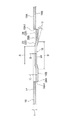
- the crimped portion 18 has a flat portion 20 and a pair of extension portions 22 , and the pair of extension portions 22 has a pair of inclined portions 23 and a pair of outer flat portions 24 .
- the flat portion 20 and the pair of extension portions 22 are connected to the main body portion 17 of the core piece 16 .
- the flat portion 20 is concave with respect to one side surface 16A of the core piece 16 and convex with respect to the other side surface of the core piece 16 .
- the flat portion 20 has a rectangular plate shape and is arranged parallel to the one side surface 16A and the other side surface 16B. As shown in FIG. 6, the depth D by which the flat portion 20 is recessed from the side surface 16A is set within the range of 0.15 to 0.85 when the thickness t of the core piece 16 is 1 ( 0.15t ⁇ D ⁇ 0.85t).
- the pair of inclined portions 23 extend obliquely from both ends of the flat portion 20 in the longitudinal direction of the crimped portion 18 toward the other side in the thickness direction of the core piece 16 on opposite sides in the longitudinal direction of the crimped portion 18 .
- Each inclined portion 23 has a rectangular plate shape, and at least a portion (here, substantially all) thereof is set thinner than the main body portion 17 (t1 ⁇ t in FIG. 6).
- a dimension B of the flat portion 20 and the pair of inclined portions 23 in the longitudinal direction of the crimped portion 18 is set larger than a dimension A of the flat portion 20 in the longitudinal direction of the crimped portion 18 (A ⁇ B).
- the pair of outer flat portions 24 extend from the ends of the pair of inclined portions 23 opposite to the flat portion 20 toward the opposite sides of the crimped portion 18 in the longitudinal direction.
- Each outer flat portion 24 has a rectangular plate shape and is arranged parallel to the one side surface 16A and the other side surface 16B. Note that "parallel" described with respect to the flat portion 20 and the outer flat portion 24 does not have to be exactly parallel, and may be approximately parallel.
- each outer flat portion 24 is recessed from the one side surface 16A is set larger than the depth D to which the flat portion 20 is recessed from the one side surface 16A (D ⁇ C). That is, each outer flat portion 24 is arranged on the other side in the thickness direction of the core piece 16 with respect to the flat portion 20 .
- the depth C by which each outer flat portion 24 is recessed from the side surface 16A is set smaller than the thickness t of the core piece 16 .
- An end portion 24A of the pair of outer flat portions 24 opposite to the pair of inclined portions 23 is an end portion of the pair of extension portions 22 opposite to the flat portion 20, and is the longitudinal end of the crimped portion 18. Department. These end portions 24A are directly connected to the main body portion 17 of the core piece 16 . An end face 24A1 facing outward in the longitudinal direction of the caulked portion 18 is formed on these end portions 24A. These end faces 24A1 are arranged perpendicularly or substantially perpendicularly to the longitudinal direction of the crimped portion 18. As shown in FIG.
- the crimped portion 18 is formed by press working using a punch and a die.
- the pair of inclined portions 23 are formed by this press working, the pair of inclined portions 23 are extended (extended) in an oblique direction in which the pair of inclined portions 23 extend from the flat portion 20 .
- the thickness of at least a portion (here, substantially all) of each inclined portion 23 is made thinner than the thickness of the flat portion 20 .
- the crimped portions 18 of the core pieces 16 are fitted to each other so that the core pieces 16 are laminated and fixed. At this time, the core pieces 16 are fixed to each other by fitting the crimping projections 18B into the crimping recesses 18A.
- the end surface 18A1 of the crimping recess 18A in the longitudinal direction of the crimping portion 18 and the end surfaces 24A1 of the pair of outer extending portions 24 are aligned in the longitudinal direction of the crimping portion 18 ( That is, they are configured to face each other and contact each other in the circumferential direction of the core pieces 16).
- the long crimped portions 18 formed on the core pieces 16 by press working are fitted to each other, and the core pieces 16 are laminated and fixed to each other.
- the crimped portion 18 has a flat portion 20 and a pair of extension portions 22 .
- the flat portion 20 is connected to the body portion 17 of the core piece 16, is concave with respect to one side surface 16A of the core piece 16, is convex with respect to the other side surface 16B of the core piece 16, and It is parallel to the side surface 16B.
- the pair of extending portions 22 extends obliquely from both ends of the flat portion 20 in the longitudinal direction of the crimped portion 18 toward the other side in the thickness direction of the core piece 16 on opposite sides in the longitudinal direction of the crimped portion 18 . It has a pair of inclined portions 23 .
- the pair of inclined portions 23 can be formed into a shape that makes it difficult for the crimped portion 18 to elastically deform in the longitudinal direction, for example, by setting the inclination angle of the core piece 16 with respect to the main body portion 17 to be small. Thereby, the longitudinal crimping rigidity of the crimping portion 18 can be increased. As a result, for example, when the core pieces 16 are laminated by in-mold roll lamination by high-speed pressing, twisting around the axis is less likely to occur between the core pieces 16 . This makes it easier to prevent the core pieces 16 from separating due to the torsion, thereby facilitating the manufacturing of the laminated core 10 .
- the flat portion 20 between the pair of inclined portions 23 is used for crimping fitting, so that the crimping force in the thickness direction of the core piece 16 can be increased.
- the pair of inclined portions 23 are at least partially thinner than the body portion 17 , the inclined portions 23 of the core pieces 16 are less likely to interfere with each other in the thickness direction of the core pieces 16 . As a result, the gap between the plates is reduced, so that the crimping rigidity and crimping force can be further increased.
- the pair of outer flat portions 24 of the pair of extension portions 22 of the crimped portion 18 are longitudinally opposite to each other from the end of the pair of inclined portions 23 opposite to the flat portion 20 . extended to the side.
- These outer flat portions 24 increase the contact area between the caulked portions 18 of the core pieces 16, so that the caulking force can be further increased. In particular, the above effects are enhanced when the core pieces 16 are made of thin plates.
- the depth of recession of the flat portion 20 from the one side surface 16A of the core piece 16 is set within the range of 0.15 to 0.85. .
- the caulking force between the caulking portions 18 in the flat portion 20 can be secured.
- the pair of extension portions 22 are directly connected to the main body portion 17 of the core piece 16 at the end portion 24A on the side opposite to the flat portion 20. Therefore, the pair of extension portions 22 is directly supported on the body portion 17 of the core piece 16 . This makes it difficult for the pair of extending portions 22 to deform unintentionally, so that the caulking force in the thickness direction of the core pieces 16 can be increased.
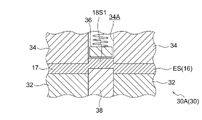
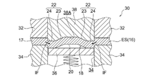
- FIGS. 8A to 11B A supplementary explanation of the effects of this embodiment will be given below with reference to FIGS. 8A to 11B.
- 30 is a mold
- 32 is a plate retainer
- 34 is a die
- 36 is a push-up mechanism
- 38 is a crimping punch.
- the electromagnetic steel sheet ES pressed against the die 34 by the plate retainer 32 is pressed by the crimping punch 38.
- a convex crimping portion 18V (dowel) is formed on the side opposite to the crimping punch 38 of the electromagnetic steel sheet ES.
- the push-up mechanism 36 separates the crimped electromagnetic steel sheet ES from the die by applying pressure (back pressure) toward the crimping punch 38 to the crimping portion 18V entering the die hole 34A.
- a large amount of material flows from the body portion 17 side to the crimped portion 18V side (see arrow IF in FIG. 8A), so it is difficult to reduce the thickness of the inclined portion of the crimped portion 18V.
- the portion 18S1 of the electromagnetic steel sheet ES is inserted into the recessed portion 38A formed in the crimping punch 38.
- the corner of this part 18S1 has an R shape, although it needs to be inserted.
- the third comparative example shown in FIGS. 10A and 10B when forming the crimped portion 18S in two steps, not only the number of man-hours increases, but also Two types of molds 30A and 30B are required, increasing manufacturing costs.
- the pair of extended portions 23 extend from the main body portion 17 side. Since less material flows into the portion 22 (see arrow IF in FIG. 11A), it is easy to reduce the thickness of the inclined portion 23 . In addition, since the flat portion 20 and the pair of inclined portions 23 can easily enter the concave portion 38A formed in the crimping punch 38, the corners between the flat portion 20 and the pair of inclined portions 23 are prevented from becoming rounded. easy.
- FIG. 12 shows a cross-sectional view of the configuration around the crimped portion 18 in the core piece 16 of the laminated core according to the second embodiment of the present disclosure.
- the caulked portion 18 the end portion 24 A of the pair of extension portions 22 opposite to the flat portion 20 is not directly connected to the main body portion 17 of the core piece 16 . Therefore, the pair of extending portions 22 can be arranged to protrude from the other side surface 16B of the core piece 16 .
- the contact area between the crimped portions 18 in the pair of extension portions 22 can be increased, so that the crimping force in the thickness direction of the core pieces 16 can be increased.
- the configuration other than the above is the same as that of the first embodiment, basically the same effects as those of the first embodiment can be obtained in points other than the above.
- FIG. 13 shows a cross-sectional view of the configuration around the crimped portion 18 in the core piece 16 of the laminated core according to the third embodiment of the present disclosure.
- the pair of extending portions 22 do not have the pair of outer flat portions 24 , but are configured only by the pair of inclined portions 23 .
- An end portion 23A of the pair of inclined portions 23 opposite to the flat portion 20 is directly connected to the main body portion 17 of the core piece 16, for example.
- An end surface 23A1 facing outward in the longitudinal direction of the crimped portion 18 is formed on these end portions 23A.
- These end faces 23A1 are arranged perpendicularly or substantially perpendicularly to the longitudinal direction of the crimped portion 18.
- the pair of extension portions 22 does not have the pair of outer flat portions 24, molding of the crimped portion 18 is easier than in the first embodiment.
- the configuration other than the above is the same as that of the first embodiment, basically the same effects as those of the first embodiment can be obtained in points other than the above.
- the end portion 23A may be configured so as not to be directly connected to the main body portion 17 of the core piece 16 .
- FIG. 14 shows a cross-sectional view of the configuration around the crimped portion 18 in the core piece 16 of the laminated core according to the fourth embodiment of the present disclosure.
- the pair of extension portions 22 are formed on the opposite sides of the crimped portion 18 in the longitudinal direction from the ends of the pair of outer flat portions 24 opposite to the pair of inclined portions 23 and on the core piece 16 .
- It has a pair of outer inclined portions 25 extending obliquely toward one side in the thickness direction.
- An end portion 25A of each outer inclined portion 25 opposite to each outer flat portion 20 is, for example, directly connected to the main body portion 17 of the core piece 16 .
- end surface 25A1 facing outward in the longitudinal direction of the crimped portion 18 is formed on these end portions 25A.
- These end faces 25A1 are arranged perpendicularly or substantially perpendicularly to the longitudinal direction of the crimped portion 18. As shown in FIG. In this embodiment, the end portion 25A may be configured so as not to be directly connected to the main body portion 17 of the core piece 16 .
- the pair of outer inclined portions 25 can guide the caulking fitting between the caulking portions 18 of the core pieces 16 . Moreover, since the pair of outer inclined portions 25 are thinner than the main body portion 17 at least in part (here, substantially all), the pair of outer inclined portions 25 interfere with each other in the thickness direction of the core piece 16. becomes difficult. As a result, gaps between plates are less likely to occur. In this embodiment, since the configuration other than the above is the same as that of the first embodiment, basically the same effects as those of the first embodiment can be obtained in points other than the above.
- FIG. 15 shows a sectional view of the configuration around the crimped portion 19 in the core piece 16 of the laminated core according to the fifth embodiment of the present disclosure.
- the crimped portion 19 is formed by connecting a plurality of (here, two) crimped portions 18 to each other in the longitudinal direction.
- the longitudinal dimension of each crimped portion 18 is set to about half that of the first embodiment.
- the outer flat portions 24 of the crimped portions 18 that are connected to each other are set short in the longitudinal dimension.
- the contact area between the crimped portions 19 can be increased.
- both ends of the crimped portion 19 in the longitudinal direction are not directly connected to the main body portion 17 of the core piece 16 .
- both ends of the crimped portion 19 in the longitudinal direction may be directly connected to the body portion 17 of the core piece 16 .
- FIG. 16 shows a cross-sectional view of the configuration around the crimped portion 19' in the core piece 16 of the laminated core according to the sixth embodiment of the present disclosure.
- This crimped portion 19' is similar to the crimped portion 19 in the fifth embodiment, and is formed by connecting two crimped portions 18 to each other in the longitudinal direction.
- the outer flat portion 24 on the side connected to each other and the outer flat portion 24 located on the opposite side of each of the two crimped portions 18 are different from each other in the thickness direction of the core piece 16 . Since it is arranged at the position, the degree of freedom in setting the caulking force between the caulking portions 18 in these outer flat portions 24 can be increased.
Landscapes
- Engineering & Computer Science (AREA)
- Power Engineering (AREA)
- Manufacturing & Machinery (AREA)
- Mechanical Engineering (AREA)
- Iron Core Of Rotating Electric Machines (AREA)
Abstract
Description
以下、図1~図11Bを参照して本開示の第1実施形態に係る積層鉄心10及びその製造方法について説明する。なお、各図においては、図面を見易くする関係から、一部の符号を省略している場合がある。
第1実施形態に係る積層鉄心10は、第1実施形態に係る積層鉄心の製造方法によって製造されたものである。この積層鉄心10は、一例としてインナロータ型モータに設けられるロータの主要部を構成するものであり、円筒状をなしている。上記のロータは磁石埋込型であり、積層鉄心10の外周部には複数の磁石挿入孔12が形成されている。これらの磁石挿入孔12には、それぞれ図示しない永久磁石が挿入される。積層鉄心10の中央部には、積層鉄心10を軸線方向に貫通した嵌合孔14が形成されている。この嵌合孔14には図示しない回転軸が挿入される。
次に、本実施形態の作用及び効果について説明する。
図12には、本開示の第2実施形態に係る積層鉄心の鉄心片16におけるかしめ部18周辺の構成が断面図にて示されている。このかしめ部18では、一対の延在部22における平坦部20とは反対側の端部24Aが鉄心片16の本体部17に対して直接繋がっていない。このため、一対の延在部22を鉄心片16の他側面16Bからより突出して配置させることができる。これにより、一対の延在部22におけるかしめ部18同士の接触面積を増加させることができるので、鉄心片16の厚み方向のかしめ力を高めることができる。この実施形態では、上記以外の構成は、第1実施形態と同様とされているため、上記以外の点では第1実施形態と基本的に同様の効果が得られる。
図13には、本開示の第3実施形態に係る積層鉄心の鉄心片16におけるかしめ部18周辺の構成が断面図にて示されている。このかしめ部18では、一対の延在部22が一対の外側平坦部24を有しておらず、一対の傾斜部23のみによって構成されている。一対の傾斜部23における平坦部20とは反対側の端部23Aは、一例として、鉄心片16の本体部17に対して直接繋がっている。これらの端部23Aには、かしめ部18の長手方向の外側を向く端面23A1が形成されている。これらの端面23A1は、かしめ部18の長手方向に対して垂直又は略垂直に配置されている。この実施形態では、一対の延在部22が一対の外側平坦部24を有していないため、第1実施形態と比較してかしめ部18の成形が容易である。この実施形態では、上記以外の構成は、第1実施形態と同様とされているため、上記以外の点では第1実施形態と基本的に同様の効果が得られる。なお、この実施形態において、上記の端部23Aが鉄心片16の本体部17に対して直接繋がっていない構成にしてもよい。
図14には、本開示の第4実施形態に係る積層鉄心の鉄心片16におけるかしめ部18周辺の構成が断面図にて示されている。このかしめ部18では、一対の延在部22は、一対の外側平坦部24における一対の傾斜部23とは反対側の端部から互いにかしめ部18の長手方向の反対側で且つ鉄心片16の厚み方向一方側へ向けて斜めに延出された一対の外側傾斜部25を有している。各外側傾斜部25における各外側平坦部20とは反対側の端部25Aは、一例として、鉄心片16の本体部17に対して直接繋がっている。これらの端部25Aには、かしめ部18の長手方向の外側を向く端面25A1が形成されている。これらの端面25A1は、かしめ部18の長手方向に対して垂直又は略垂直に配置されている。なお、この実施形態において、上記の端部25Aが鉄心片16の本体部17に対して直接繋がっていない構成にしてもよい。
図15には、本開示の第5実施形態に係る積層鉄心の鉄心片16におけるかしめ部19周辺の構成が断面図にて示されている。このかしめ部19は、複数(ここでは2個)のかしめ部18が各々の長手方向に互いに繋がって形成されている。但し、各かしめ部18の長手方向寸法は、第1実施形態の半分程度に設定されている。特に、各かしめ部18において互いに繋がる側の外側平坦部24は、上記長手方向寸法が短く設定されている。この実施形態では、かしめ部19が複数のかしめ部18によって構成されているので、例えばかしめ部19同士の接触面積を増加させることができる。その結果、鉄心片16の厚み方向のかしめ力を高めることができる。また、かしめ部19の長手方向の両端部は、鉄心片16の本体部17に対して直接繋がっていない構成になっている。これにより、第2実施形態と同様の効果が得られる。この実施形態では、上記以外の構成は、第1実施形態と同様とされているため、上記以外の点では第1実施形態と基本的に同様の効果が得られる。なお、この実施形態において、かしめ部19の長手方向の両端部が鉄心片16の本体部17に対して直接繋がっている構成にしてもよい。
図16には、本開示の第6実施形態に係る積層鉄心の鉄心片16におけるかしめ部19’周辺の構成が断面図にて示されている。このかしめ部19’は、第5実施形態におけるかしめ部19に類似しており、2個のかしめ部18が各々の長手方向に互いに繋がって形成されている。但し、このかしめ部19’では、2個の各かしめ部18において、互いに繋がる側の外側平坦部24と、互いに反対側に位置する外側平坦部24とが、鉄心片16の厚み方向において互いに異なる位置に配置されているので、これらの外側平坦部24におけるかしめ部18同士のかしめ力の設定自由度を高めることができる。
Claims (9)
- プレス加工によって各鉄心片に形成する長尺なかしめ部を互いに嵌合させて前記各鉄心片同士を積層固定し、積層鉄心を製造する積層鉄心の製造方法であって、
前記かしめ部を形成する際に、
前記鉄心片の本体部に接続され、前記鉄心片の厚み方向一方側の面に対して凹をなし、前記鉄心片の厚み方向他方側の面に対して凸をなし、且つ前記各面に対して平行をなす平坦部と、
前記かしめ部の長手方向における前記平坦部の両端から互いに前記長手方向の反対側で且つ前記厚み方向他方側へ向けて斜めに延出される一対の傾斜部を有する一対の延在部と、
を形成し、
前記一対の傾斜部を形成する際に、前記斜めの方向に前記一対の傾斜部を延伸させる積層鉄心の製造方法。 - プレス加工によって各鉄心片に形成される長尺なかしめ部が互いに嵌合されて前記各鉄心片同士が積層固定されてなる積層鉄心であって、
前記かしめ部は、
前記鉄心片の本体部に接続され、前記鉄心片の厚み方向一方側の面に対して凹をなし、前記鉄心片の厚み方向他方側の面に対して凸をなし、且つ前記各面に対して平行をなす平坦部と、
前記かしめ部の長手方向における前記平坦部の両端から互いに前記長手方向の反対側で且つ前記厚み方向他方側へ向けて斜めに延出され、少なくとも一部で前記鉄心片の本体部よりも厚みが薄い一対の傾斜部を有する一対の延在部と、
を備える積層鉄心。 - 前記一対の延在部は、前記一対の傾斜部における前記平坦部とは反対側の端部から互いに前記長手方向の反対側へ向けて延出され、前記各面に対して平行をなす一対の外側平坦部を有する請求項2に記載の積層鉄心。
- 前記鉄心片の厚みを1とした場合、前記厚み方向一方側の面から前記平坦部が凹む深さが0.15~0.85の範囲内に設定される請求項2又は請求項3に記載の積層鉄心。
- 前記一対の延在部は、前記平坦部とは反対側の端部が前記本体部に対して直接繋がる請求項2~請求項4の何れか1項に記載の積層鉄心。
- 前記一対の延在部は、前記平坦部とは反対側の端部が前記本体部に対して直接繋がらない請求項2~請求項4の何れか1項に記載の積層鉄心。
- 前記各鉄心片には、複数の前記かしめ部が各々の長手方向に互いに繋がって形成される請求項2~請求項6の何れか1項に記載の積層鉄心。
- 前記一対の延在部は、前記一対の外側平坦部における前記一対の傾斜部とは反対側の端部から互いに前記長手方向の反対側で且つ前記厚み方向一方側へ向けて斜めに延出され、少なくとも一部で前記本体部よりも厚みが薄い一対の外側傾斜部を有する請求項3又は請求項3を引用する請求項4~請求項7の何れか1項に記載の積層鉄心。
- 前記各外側平坦部は、前記厚み方向において互いに異なる位置に配置されるものを含む請求項3又は請求項3を引用する請求項4~請求項7の何れか1項に記載の積層鉄心。
Priority Applications (3)
| Application Number | Priority Date | Filing Date | Title |
|---|---|---|---|
| CN202280015838.0A CN116897496A (zh) | 2021-03-15 | 2022-03-02 | 层叠铁芯的制造方法以及层叠铁芯 |
| JP2022553689A JP7464740B2 (ja) | 2021-03-15 | 2022-03-02 | 積層鉄心の製造方法及び積層鉄心 |
| US18/548,768 US20240154478A1 (en) | 2021-03-15 | 2022-03-02 | Laminated iron core manufacturing method and laminated iron core |
Applications Claiming Priority (2)
| Application Number | Priority Date | Filing Date | Title |
|---|---|---|---|
| JP2021-041801 | 2021-03-15 | ||
| JP2021041801 | 2021-03-15 |
Publications (1)
| Publication Number | Publication Date |
|---|---|
| WO2022196359A1 true WO2022196359A1 (ja) | 2022-09-22 |
Family
ID=83322316
Family Applications (1)
| Application Number | Title | Priority Date | Filing Date |
|---|---|---|---|
| PCT/JP2022/008852 WO2022196359A1 (ja) | 2021-03-15 | 2022-03-02 | 積層鉄心の製造方法及び積層鉄心 |
Country Status (4)
| Country | Link |
|---|---|
| US (1) | US20240154478A1 (ja) |
| JP (1) | JP7464740B2 (ja) |
| CN (1) | CN116897496A (ja) |
| WO (1) | WO2022196359A1 (ja) |
Citations (4)
| Publication number | Priority date | Publication date | Assignee | Title |
|---|---|---|---|---|
| JPH07185695A (ja) * | 1993-12-28 | 1995-07-25 | Mitsui High Tec Inc | 積層固着品のかしめ構造 |
| WO2008023448A1 (fr) * | 2006-08-22 | 2008-02-28 | Japan Metal Gasket Co., Ltd. | structure de liaison pour une plaque métallique |
| JP2011125141A (ja) * | 2009-12-10 | 2011-06-23 | Toyota Motor Corp | ステータコアおよびステータコアの製造方法 |
| US20120169175A1 (en) * | 2010-12-29 | 2012-07-05 | Samsung Electronics Co., Ltd. | Motor, manufacturing method for the same and washing machine |
Family Cites Families (2)
| Publication number | Priority date | Publication date | Assignee | Title |
|---|---|---|---|---|
| JPS56123775U (ja) * | 1980-02-18 | 1981-09-21 | ||
| JP6537296B2 (ja) | 2015-02-18 | 2019-07-03 | 株式会社三井ハイテック | 仮カシメを有する積層体及びその製造方法並びに積層鉄心の製造方法 |
-
2022
- 2022-03-02 CN CN202280015838.0A patent/CN116897496A/zh active Pending
- 2022-03-02 US US18/548,768 patent/US20240154478A1/en active Pending
- 2022-03-02 WO PCT/JP2022/008852 patent/WO2022196359A1/ja active Application Filing
- 2022-03-02 JP JP2022553689A patent/JP7464740B2/ja active Active
Patent Citations (4)
| Publication number | Priority date | Publication date | Assignee | Title |
|---|---|---|---|---|
| JPH07185695A (ja) * | 1993-12-28 | 1995-07-25 | Mitsui High Tec Inc | 積層固着品のかしめ構造 |
| WO2008023448A1 (fr) * | 2006-08-22 | 2008-02-28 | Japan Metal Gasket Co., Ltd. | structure de liaison pour une plaque métallique |
| JP2011125141A (ja) * | 2009-12-10 | 2011-06-23 | Toyota Motor Corp | ステータコアおよびステータコアの製造方法 |
| US20120169175A1 (en) * | 2010-12-29 | 2012-07-05 | Samsung Electronics Co., Ltd. | Motor, manufacturing method for the same and washing machine |
Also Published As
| Publication number | Publication date |
|---|---|
| CN116897496A (zh) | 2023-10-17 |
| JPWO2022196359A1 (ja) | 2022-09-22 |
| US20240154478A1 (en) | 2024-05-09 |
| JP7464740B2 (ja) | 2024-04-09 |
Similar Documents
| Publication | Publication Date | Title |
|---|---|---|
| EP2026448B1 (en) | Split core and manufacturing method of the same, and stator core | |
| US7019433B2 (en) | Armature of rotating electric machine | |
| JP2002034187A (ja) | 磁石埋込型回転子 | |
| KR101679470B1 (ko) | 모터의 적층 코어 및 제조 방법 | |
| WO2017216995A1 (ja) | 永久磁石式同期機および永久磁石式同期機の固定子の製造方法 | |
| JP2002247784A (ja) | 磁石埋込型回転子 | |
| JP2006238678A (ja) | 磁性体、回転子、電動機 | |
| WO2012095987A1 (ja) | 回転電機の積層鉄心及びその製造方法 | |
| JP3674599B2 (ja) | 電動機鉄心、電動機及び電動機鉄心の製造方法 | |
| JP2013080853A (ja) | 積層鉄心及びその製造方法 | |
| JP3869731B2 (ja) | アモルファス積層コアの製造方法 | |
| US10566863B2 (en) | Rotor for rotary electric machine, rotary electric machine provided with same, and method for manufacturing rotor for rotary electric machine | |
| JP5251384B2 (ja) | 積層コアおよびその製造方法 | |
| JP5441360B2 (ja) | 電動機の固定子 | |
| WO2022196359A1 (ja) | 積層鉄心の製造方法及び積層鉄心 | |
| JP6948177B2 (ja) | 積層鉄心及びその製造方法 | |
| JP2003061319A (ja) | ステータの製造方法 | |
| JPH05219668A (ja) | 永久磁石式回転子 | |
| JP6447206B2 (ja) | 回転電機のロータ及びその製造方法 | |
| JP6912503B2 (ja) | 防水性を高めたステータコア及び電動機 | |
| JP3403682B2 (ja) | 磁石埋込型回転子および成形治具 | |
| JP5462643B2 (ja) | 積層鉄心及びその製造方法 | |
| JP6727458B2 (ja) | 固定子鉄心及びその固定子鉄心を備えた電動機 | |
| WO2011125209A1 (ja) | ロータ及びその製造方法 | |
| JP2018182795A (ja) | 電動モータのロータ製造方法及び電動モータのロータ |
Legal Events
| Date | Code | Title | Description |
|---|---|---|---|
| ENP | Entry into the national phase |
Ref document number: 2022553689 Country of ref document: JP Kind code of ref document: A |
|
| 121 | Ep: the epo has been informed by wipo that ep was designated in this application |
Ref document number: 22771113 Country of ref document: EP Kind code of ref document: A1 |
|
| WWE | Wipo information: entry into national phase |
Ref document number: 202280015838.0 Country of ref document: CN |
|
| WWE | Wipo information: entry into national phase |
Ref document number: 18548768 Country of ref document: US |
|
| NENP | Non-entry into the national phase |
Ref country code: DE |
|
| 122 | Ep: pct application non-entry in european phase |
Ref document number: 22771113 Country of ref document: EP Kind code of ref document: A1 |