WO2022196331A1 - 物質導入装置及び物質導入ユニット - Google Patents
物質導入装置及び物質導入ユニット Download PDFInfo
- Publication number
- WO2022196331A1 WO2022196331A1 PCT/JP2022/008432 JP2022008432W WO2022196331A1 WO 2022196331 A1 WO2022196331 A1 WO 2022196331A1 JP 2022008432 W JP2022008432 W JP 2022008432W WO 2022196331 A1 WO2022196331 A1 WO 2022196331A1
- Authority
- WO
- WIPO (PCT)
- Prior art keywords
- electrode surface
- substance introduction
- substance
- introduction unit
- channel
- Prior art date
- Legal status (The legal status is an assumption and is not a legal conclusion. Google has not performed a legal analysis and makes no representation as to the accuracy of the status listed.)
- Ceased
Links
Images

Classifications
-
- C—CHEMISTRY; METALLURGY
- C12—BIOCHEMISTRY; BEER; SPIRITS; WINE; VINEGAR; MICROBIOLOGY; ENZYMOLOGY; MUTATION OR GENETIC ENGINEERING
- C12M—APPARATUS FOR ENZYMOLOGY OR MICROBIOLOGY; APPARATUS FOR CULTURING MICROORGANISMS FOR PRODUCING BIOMASS, FOR GROWING CELLS OR FOR OBTAINING FERMENTATION OR METABOLIC PRODUCTS, i.e. BIOREACTORS OR FERMENTERS
- C12M1/00—Apparatus for enzymology or microbiology
- C12M1/42—Apparatus for the treatment of microorganisms or enzymes with electrical or wave energy, e.g. magnetism, sonic waves
Definitions
- the present disclosure relates to a substance introduction device and a substance introduction unit.
- Patent Literature 1 discloses an electroporation device having a plurality of wells for performing electroporation.
- An object of the present disclosure which has been made in view of such circumstances, is to provide a substance introduction device and a substance introduction unit that improve the usefulness of techniques for introducing substances into cells by electroporation.
- a substance introduction device is a substance introduction device that introduces a substance into cells by electroporation, and includes a substance introduction unit and a voltage applying section, the substance introduction unit facing a first electrode surface and a second electrode surface that are arranged in parallel with each other; and a flow that is disposed between the first electrode surface and the second electrode surface and can accommodate a cell suspension containing the cells and the substance.
- an accommodation portion defining a channel therein, wherein the channel has one or more turbulence generating structures, and the voltage applying portion is positioned between the first electrode surface and the second electrode surface. A voltage can be applied.
- the substance introduction unit is preferably removable from the substance introduction device.
- a substance introduction unit is a substance introduction unit used for introduction of a substance into cells by electroporation, comprising a first electrode surface and a second electrode surface arranged to face each other; a storage unit that is disposed between the first electrode surface and the second electrode surface and defines a channel that can store a cell suspension containing the cells and the substance, wherein the channel has one or more turbulator structures.
- the channel is a tubular channel having one or more curved portions as a turbulent flow generating structure.
- the channel is provided with one or more barriers as a turbulence generating structure.
- the storage section includes an injection port that defines a flow of the cell suspension in a direction in which the cell suspension is injected into the channel; a discharge port defining a flow of said cell suspension in a direction to discharge liquid from said channel.
- the accommodating portion is a flexible bag-like accommodating portion made of a conductive material.
- the storage section is removable from the substance introduction unit.
- the substance introduction device and the substance introduction unit according to the present disclosure it is possible to improve the usefulness of techniques for introducing substances into cells by electroporation.
- FIG. 1 is a schematic diagram showing a schematic configuration of a substance introduction device according to an embodiment of the present disclosure
- FIG. 2 is a side view of the substance introduction device shown in FIG. 1
- FIG. FIG. 2 is a cross-sectional view of the substance introduction unit shown in FIG. 1 taken along line I-I'
- 2 is a cross-sectional view of the substance introduction unit shown in FIG. 1 taken along line II-II'
- FIG. FIG. 5 is a modified example of the flow path of the housing portion shown in FIG. 4.
- FIG. FIG. 5 is a second modification of the flow path of the housing shown in FIG. 4
- FIG. FIG. 3 is a schematic diagram showing a schematic configuration of a modified example of the substance introduction unit shown in FIG. 1
- FIG. 8 is a cross-sectional view of the substance introduction unit shown in FIG. 7 taken along line III-III'
- FIG. 8 is a cross-sectional view of the substance introduction unit shown in FIG. 7 taken along line IV-IV';
- a substance introduction device 1 according to an embodiment of the present disclosure will be described below with reference to the drawings.
- the substance introduction device 1 introduces substances into cells by electroporation.
- Electroporation is a method of applying an electric pulse or the like to cells and a cell suspension containing a substance to be introduced into the cells to perforate the cell membrane of the cells and introduce a substance into the cells. Electroporation is also called electroporation.
- the cell suspension includes, for example, animal cells or cells such as E. coli, genes, deoxyribonucleic acid (DNA), ribonucleic acid (RNA), nucleic acids, proteins, low-molecular-weight compounds, lipid molecules, or liposomes. and are suspended in a buffer solution (buffer).
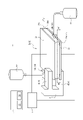
- FIG. 1 is a schematic diagram showing a schematic configuration of a substance introduction device 1.
- FIG. 2 is a side view of the substance introduction device 1.
- the substance introduction device 1 includes a substance introduction unit 2A, a voltage applying section 3, a holding section 4, and a control section 5. As shown in FIG.
- the substance introduction unit 2A is used to introduce substances into cells by electroporation.
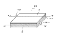
- the substance introduction unit 2A includes a first electrode 21, a second electrode 22, a housing portion 23A, and a port 24.
- the substance introduction unit 2A is removable from the substance introduction device 1.
- the substance introduction unit 2A is fixed to the substance introduction device 1 by being attached to the holding portion 4 of the substance introduction device 1 .
- the substance introduction unit 2A can be removed from the substance introduction device 1 and carried as a container containing the introduced cell suspension into which the substance has been introduced into the cells by electroporation. can.
- the substance introduction unit 2A may be formed integrally with the substance introduction device 1, and may not be removable from the substance introduction device 1.
- the first electrode 21 is an electrode having a substantially rectangular flat first electrode surface 21A.
- the first electrode 21 is a plate-like electrode.
- the shape of the first electrode 21 is not limited to a plate shape, and may be any shape having the first electrode surface 21A.
- the first electrode 21 is made of an electrically conductive material such as a metal or a conductive polymer.
- the second electrode 22 is an electrode having a substantially rectangular flat second electrode surface 22A.
- the second electrode 22 is a substantially rectangular plate-shaped electrode.
- the shape of the second electrode 22 is not limited to a plate shape, and may be any shape having a second electrode surface 22A.
- the second electrode 22 is made of an electrically conductive material, such as a metal or a conductive polymer.
- the first electrode surface 21A and the second electrode surface 22A are arranged to face each other. More specifically, the second electrode surface 22A faces the first electrode surface 21A in a direction perpendicular to the first electrode surface 21A. That is, the facing direction of the first electrode surface 21A and the second electrode surface 22A in the present embodiment is a vertical direction perpendicular to the first electrode surface 21A and the second electrode surface 22A.
- the facing direction of the first electrode surface 21A and the second electrode surface 22A may be simply referred to as the "facing direction".
- the first electrode surface 21A and the second electrode surface 22A have the same shape and overlap each other when viewed from the direction perpendicular to the first electrode surface 21A.
- the fact that the second electrode surface 22A faces the first electrode surface 21A in the direction perpendicular to the first electrode surface 21A means that when viewed from the direction perpendicular to the first electrode surface 21A, the first electrode surface 21A It is not limited to completely overlapping the second electrode surface 22A, and includes overlapping of at least a portion of the first electrode surface 21A and the second electrode surface 22A. Also, the first electrode surface 21A and the second electrode surface 22A may not have the same shape, and may have different sizes.
- the storage section 23A is configured to store a cell suspension containing cells and a substance to be introduced into the cells.
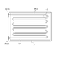
- the containing portion 23A has a channel 234 inside which can contain the cell suspension.
- the flow path 234 of the housing portion 23A has one or more turbulence generating structures. As a result, turbulence is generated in the cell suspension and the cell suspension is agitated by passing through the channel 234 between the time when the cell suspension is injected into the storage section 23A and before it is discharged. be. Therefore, the substance introduction unit 2A can improve the mixing state of the cells in the cell suspension and the substance to be introduced into the cells, and can more uniformly introduce the substance into the cells.
- Channel 234 may be, for example, a tubular channel formed of an electrically conductive material.
- a tubular flow path may be, for example, a flow path partitioned by the containing portion 23A itself formed of a conductive material, or a flow partitioned by embedding a liquid-feeding tube in the containing portion 23A. It can be a road.
- a portion of the housing portion 23A other than the flow path 234 may be hollow or may be filled with a conductive material.
- the housing portion 23A is arranged between the first electrode surface 21A and the second electrode surface 22A. Specifically, the housing portion 23A is in a state in which it can be sandwiched between the first electrode surface 21A and the second electrode surface 22A without leaving a gap between the outer surface thereof and the first electrode surface 21A and the second electrode surface 22A. are placed in More specifically, as shown in FIG. 2, in a state in which the storage section 23A is filled with the cell suspension, the storage section 23A has an upper surface 231 in contact with the first electrode surface 21A and a lower surface 232 in contact with the second electrode surface 22A.
- the housing portion 23A is positioned between the first electrode surface 21A and the second electrode surface 22A. are placed.
- the housing portion 23A is configured to be removable from the first electrode surface 21A and the second electrode surface 22A.
- the housing portion 23A is held by the holding portion 4 in a state of being sandwiched between the first electrode surface 21A and the second electrode surface 22A without being adhered or the like. By doing so, the accommodating portion 23A of the present embodiment can be removed from the first electrode surface 21A and the second electrode surface 22A.
- the container 23A is removed from the substance introduction device 1 and the first electrode 21 and the second electrode 22, which together constitute the substance introduction unit 2A, and the introduced cell suspension is removed.
- the accommodating portion 23A may be fixed to the first electrode surface 21A and the second electrode surface 22A by adhesion or the like, and may not be removable.
- the housing portion 23A is a flexible bag-like container made of a conductive material such as a conductive polymer.
- the conductive material is softer than the material of the first electrode 21 and the second electrode 22 so that the shape of the housing portion 23A is deformed by being sandwiched between the first electrode 21 and the second electrode 22 .
- the changeable shape of the accommodating portion 23A enables the change of the facing distance between the first electrode surface 21A and the second electrode surface 22A in the substance introduction unit 2A. For example, by pressing the surface of the first electrode 21 opposite to the first electrode surface 21A and the surface of the second electrode 22 opposite to the second electrode surface 22A, the shape of the accommodating portion 23A is deformed. Thus, the distance between the first electrode surface 21A and the second electrode surface 22A can be shortened. As a result, the distance between the first electrode surface 21A and the second electrode surface 22A is changed according to the type or amount of the cell suspension contained in the flow channel 234 of the containing portion 23A. A suitable distance can be used to
- the port 24 is a tubular member capable of injecting the cell suspension into the flow path 234 of the storage section 23A or discharging it from the flow path 234 of the storage section 23A.
- the port 24 is provided on a side surface 233 other than the upper surface 231 and the lower surface 232 of the housing portion 23A. This makes the port 24 less likely to interfere with electroporation.
- the port 24 has, for example, an open/close valve. In such a case, by opening the valve of the port 24, it is possible to inject the cell suspension into the channel 234 of the container 23A or release the cell suspension from the channel 234 of the container 23A.
- the ports 24 may include an injection port 24A and an ejection port 24B.
- the injection port 24A and the discharge port 24B are each provided with a check valve or the like to regulate the flow of the cell suspension flowing therein.
- the injection port 24A regulates the flow of the cell suspension in the direction of injecting the cell suspension into the channel 234 of the housing portion 23A.
- the injection port 24A may be connected to the pre-introduction bag 10 containing the cell suspension before electroporation by a liquid delivery tube.
- the discharge port 24B regulates the flow of the cell suspension in the direction of discharging the cell suspension from the channel 234 of the container 23A.
- the discharge port 24B may be connected to the introduced bag 11 containing the cell suspension after electroporation by means of a liquid delivery tube.
- the injection port 24A and the discharge port 24B are provided at positions on both sides of the upper surface 231 of the side surface 233 of the housing portion 23A in a plan view along the opposing direction.
- a cell suspension in which cells and a substance to be introduced into the cells are previously suspended in a buffer solution (buffer) is used, but the present invention is not limited to this.
- a cell suspension containing cells and a substance to be introduced into the cells may be mixed at the timing of pouring into the storage portion 23A, or may be poured into the storage portion 23A at different timings, and may be mixed in the storage portion 23A. may be mixed with
- the voltage applying section 3 applies a voltage between the first electrode surface 21A and the second electrode surface 22A.
- the voltage application unit 3 is not particularly limited as long as it can apply a voltage between the first electrode surface 21A and the second electrode surface 22A.
- the voltage application unit 3 may be, for example, a storage battery or a dry battery.
- the voltage application unit 3 may be configured to receive power supply from the external power supply, for example, by including an adapter or the like for receiving power supply from the external power supply.
- the voltage application unit 3 is connected to the first electrode 21 and the second electrode 22 by a lead wire or the like so as to be able to supply power, as indicated by solid lines in FIG.
- the voltage application unit 3 applies a predetermined voltage between the first electrode 21 and the second electrode 22, thereby applying a voltage to the cell suspension accommodated in the flow channel 234 of the accommodation unit 23A, Substances are introduced into cells by electroporation.
- the cell suspension is injected from the injection port 24A into the channel 234 of the housing portion 23A.
- the voltage application section 3 operates the first electrode surface 21A and the second electrode surface with the injection port 24A and the discharge port 24B closed.
- a voltage is applied between 22A.
- the cell suspension is discharged from discharge port 24B.
- air or a buffer solution may be injected into the channel 234 from the injection port 24A.
- the cell suspension in the channel 234 of the storage section 23A can be collected without leaving any residue.
- the voltage A voltage may be applied by the application unit 3 .
- the length of the flow path 234 of the storage section 23A may be designed according to the execution time of electroporation, the flow rate of the cell suspension, and the like.
- the holding part 4 holds the substance introduction unit 2A.
- the holding section 4 includes a first holding member 41 and a second holding member 42 .
- one of the first holding member 41 and the second holding member 42 supports one of the first electrode 21 and the second electrode 22 .
- the substance introduction unit 2 is held by the holding portion 4 .
- the second holding member 42 is configured to support the substance introduction unit 2 from the side of the second electrode 22 opposite to the second electrode surface 22A. That is, in this embodiment, the substance introduction unit 2 is held by the holding section 4 by being supported by the second holding member 42 of the holding section 4 .
- the holding part 4 presses the first electrode 21 from the surface opposite to the first electrode surface 21A of the first electrode 21 with the first holding member 41, and presses the second electrode 22 with the second holding member 42.
- the substance introduction unit 2A can be sandwiched by pressing the second electrode 22 from the surface opposite to the second electrode surface 22A.
- the holding section 4 may have any structure capable of holding the substance introduction unit 2A.
- the holding part 4 is made of an insulating material such as plastic, glass, silicon, or quartz.
- the control unit 5 includes a memory 51 and a processor 52, for example.
- a computer such as an electroporator, a personal computer, a smart phone, or a tablet terminal may be used.
- the memory 51 is, for example, a semiconductor memory, a magnetic memory, an optical memory, or the like.
- the memory 51 functions, for example, as a main memory device, an auxiliary memory device, or a cache memory.
- the memory 51 stores arbitrary information used for the operation of the substance introduction device 1 .
- the memory 51 stores system programs, application programs, embedded software, and the like.
- the processor 52 may be, for example, a general-purpose processor such as a CPU (Central Processing Unit), or a dedicated processor specialized for specific processing.
- the processor 52 may include, for example, a dedicated circuit such as an FPGA (Field-Programmable Gate Array) or an ASIC (Application Specific Integrated Circuit).
- the control unit 5 is communicably connected to the voltage applying unit 3 by wire or wirelessly, as indicated by the dashed line in FIG. Thereby, the control unit 5 controls components such as the voltage application unit 3 in order to realize the function of the substance introduction device 1 . Specifically, the control unit 5 can control the voltage application unit 3 to apply a predetermined voltage between the first electrode surface 21A and the second electrode surface 22A.
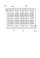
- FIG. 3 is a cross-sectional view of the substance introduction unit 2A taken along line I-I' shown in FIG. Specifically, FIG. 3 is a cross-sectional view of the substance introduction unit 2A shown in FIG. 1 cut along the line I-I' in the opposite direction.
- FIG. 4 is a cross-sectional view along II-II' of the substance introduction unit 2A shown in FIG. Specifically, FIG. 4 is a cross-sectional view of the substance introduction unit 2A shown in FIG. 1 cut along II-II' in a direction orthogonal to the facing direction (a direction along the first electrode surface 21A in this embodiment). is.
- Channel 234 may be a tubular channel having one or more bends 235 as turbulence-generating structures. As the cell suspension passes through the bend 235, turbulence is generated and the cell suspension is agitated. This prevents uneven distribution of cells due to sedimentation of cells in the cell suspension, and the storage section 23A enables more uniform introduction of the substance to the cells. In addition, after electroporation, the container 23A increases the chances of contact between the cells with holes in the cell membrane and the substances to be introduced into the cells, thereby promoting the introduction of substances into the cells.
- the flow path 234 since the flow path 234 has the bent portion 235, the flow path 234 can be installed at a higher density in the housing portion 23A, and the length of the flow path 234 can be increased.
- the shape and size of the cross section of the channel 234 can be arbitrarily determined according to the amount and type of cell suspension to be processed in one electroporation, but for example, it is circular with a diameter of 1 mm to several mm. may Also, the volume of the entire channel 234 is arbitrarily determined according to the amount of cell suspension processed in one electroporation, and is, for example, 100 milliliters.
- the flow path 234 of the housing portion 23A has a bent portion 235A shown in a cross-sectional view along the facing direction as shown in FIG. and portion 235B.
- the bent portion 235A shown in FIG. 3 bends in the out-of-plane direction, which is the direction intersecting the first electrode surface 21A and the second electrode surface 22A.
- the bent portion 235B shown in FIG. 4 bends in the in-plane direction, which is the direction along the first electrode surface 21A and the second electrode surface 22A. That is, the flow path 234 of the housing portion 23A is three-dimensionally (three-dimensionally) curved.
- the flow path 234 of the housing portion 23A has either a bent portion 235A bent in the out-of-plane direction or a bent portion 235B bent in the in-plane direction, and is bent planarly (two-dimensionally).
- bent portion 235A and 235B when the bent portions 235A and 235B are not particularly distinguished, they will simply be collectively referred to as the bent portion 235.
- FIG. 1 when the bent portions 235A and 235B are not particularly distinguished, they will simply be collectively referred to as the bent portion 235.
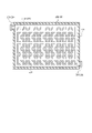
- FIG. 5 shows a modification of the flow path 234 of the housing portion 23A shown in FIG.
- FIG. 5 is a cross-sectional view of the accommodating portion 23A at the same position as in FIG.
- channel 234 may be a plurality of straight channels connected via U-shaped bends 235 .
- the injection port 24A and the discharge port 24B may be provided in the same direction with respect to the accommodating portion 23A in plan view along the opposing direction.
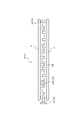
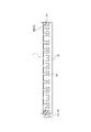
- FIG. 6 is a diagram showing a second modification of the flow path 234 of the housing portion 23A.
- one or more barriers 236 may be provided as turbulence generating structures in the flow path 234 of the housing portion 23A.
- barriers 236 may be provided to narrow the cross-section of a portion of channel 234 . This creates turbulence and agitates the cell suspension as it passes through the barrier 236, as indicated by the arrows in FIG. According to such a configuration, it is not necessary to provide the curved portion 235 in the flow path 234 in order to generate turbulence in the flow path 234, and the shape of the housing portion 23A can be designed more flexibly.
- the housing portion 23A can be formed into an elongated shape.
- the flow path 234 of the housing portion 23A may have both the curved portion 235 and the barrier 236 as the turbulence generating structure.
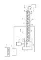
- FIG. 7 is a schematic diagram showing a schematic configuration of the substance introduction unit 2B.
- FIG. 8 is a cross-sectional view along III-III' of the substance introduction unit 2B shown in FIG. Specifically, FIG. 8 is a cross-sectional view of the substance introduction unit 2B shown in FIG. 7 taken along line III-III' in the opposite direction.
- FIG. 9 is a cross-sectional view of the substance introduction unit 2B taken along IV-IV' shown in FIG. Specifically, FIG. 9 is a cross-sectional view of the substance introduction unit 2B shown in FIG.
- the substance introduction unit 2B differs from the substance introduction unit 2A in that the containing portion 23B is not a bag-like container.
- the substance introduction unit 2B will be described below, focusing on the differences from the substance introduction unit 2A. Parts having the same configuration as the substance introduction unit 2A are denoted by the same reference numerals.
- the substance introduction units 2A and 2B when the substance introduction units 2A and 2B are not particularly distinguished, they will simply be collectively referred to as the substance introduction unit 2.
- FIG. when the accommodating portions 23A and 23B are not particularly distinguished, they are simply referred to collectively as the accommodating portion 23. As shown in FIG.
- the substance introduction unit 2B includes a first electrode 21, a second electrode 22, a housing portion 23B, and a port 24.
- the substance introduction unit 2B may be removable from the substance introduction device 1, like the substance introduction unit 2A. As a result, after electroporation, the substance introduction unit 2B can be removed from the substance introduction device 1 and carried as a container containing the introduced cell suspension.
- the accommodating portion 23B is arranged between the first electrode surface 21A of the first electrode 21 and the second electrode surface 22A of the second electrode 22.
- the housing portion 23B is an insulating material that surrounds the sides of the space sandwiched between the first electrode surface 21A and the second electrode surface 22A. It has sidewalls 237 formed of.
- the insulating material may be, for example, plastic, glass, silicon, or quartz.
- At least the side wall 237 of the housing portion 23B is hard enough to stand on its own even under the weight of the first electrode 21 and the second electrode 22, unlike the side wall of the flexible bag-shaped housing portion 23A. Constructed of materials.
- the side wall 237 is fixed to the first electrode surface 21A and the second electrode surface 22A by adhesion or the like. Thereby, the distance between the first electrode surface 21A and the second electrode surface 22A is always kept constant.
- the port 24 is provided on the side wall 237 of the housing portion 23B. This makes the port 24 less likely to interfere with electroporation.
- Ports 24 may include an injection port 24A and an ejection port 24B, similar to substance introduction unit 2A.
- the injection port 24A and the discharge port 24B are provided at positions on both sides of the side wall 237 of the accommodating portion 23B on both sides of the first electrode surface 21A in plan view along the opposing direction.
- the containing portion 23B defines therein a channel 234 capable of containing a cell suspension containing cells and substances.
- the channel 234 of the housing portion 23B has one or more turbulence generating structures. As shown in FIG. 9, the channel 234 of the housing portion 23B continues from the injection port 24A to the discharge port 24B.
- the channel 234 may be configured by, for example, a liquid-sending tube made of a conductive material and embedded in the housing portion 23B.
- a portion of the housing portion 23B other than the flow path 234 may be hollow or may be filled with a conductive material.
- the shape and structure of the channel 234 of the accommodating portion 23B may be the shape and structure of the channel 234 of the substance introduction unit 2A described above, or the shape and structure of the modified example of the channel 234 .
- the substance introduction device 1 is a substance introduction device 1 that introduces substances into cells by electroporation, and includes the substance introduction unit 2 and the voltage application section 3 .
- the substance introduction unit 2 is arranged between a first electrode surface 21A and a second electrode surface 22A which are arranged to face each other, and between the first electrode surface 21A and the second electrode surface 22A. and a storage section 23 that defines a channel 234 that can store turbid liquid.
- the channel 234 of the housing portion 23 has one or more turbulence generating structures.
- the voltage applying section 3 can apply a voltage between the first electrode surface 21A and the second electrode surface 22A.
- the substance introduction device 1 can improve the mixing state of the cells in the cell suspension and the substance to be introduced into the cells, thereby enabling more uniform introduction of the substance into the cells. Therefore, the substance introduction device 1 can improve the usefulness of techniques for introducing substances into cells by electroporation.
- the substance introduction unit 2 is preferably removable from the substance introduction device 1. According to such a configuration, after electroporation, the substance introduction unit 2 can be removed from the substance introduction device 1 and carried as a container containing the introduced cell suspension.
- the substance introduction unit 2 is a substance introduction unit 2 used for introducing substances into cells by electroporation, and includes a first electrode surface 21A and a second electrode surface 22A that are arranged to face each other, A storage section 23 that is arranged between the first electrode surface 21A and the second electrode surface 22A and defines a flow path 234 that can store a cell suspension containing cells and substances.
- channel 234 has one or more turbulation structures therein. According to such a configuration, turbulence is generated in the cell suspension by passing through the channel 234 from the time the cell suspension is injected into the storage section 23 to the time it is discharged. is stirred.
- the substance introduction unit 2 can improve the mixing state of the cells in the cell suspension and the substance to be introduced into the cells, enabling more uniform introduction of the substance into the cells. Therefore, the substance introduction unit 2 can improve the usefulness of techniques for introducing substances into cells by electroporation.
- the channel 234 is preferably a tubular channel 234 having one or more bent portions 235 as the turbulence generating structure. According to such a configuration, the substance introduction unit 2 can install the flow paths 234 at a higher density in the storage section 23, and the length of the flow paths 234 provided in the storage section 23A can be increased.
- the channel 234 is preferably provided with one or more barriers 236 as a turbulence generating structure. According to such a configuration, the substance introduction unit 2 does not necessarily need to provide the channel 234 with the curved portion 235 in order to generate turbulent flow in the channel 234, and the shape of the accommodation section 23 can be designed more flexibly. can be done.
- the storage section 23 includes an injection port 24A that defines the flow of the cell suspension in the direction of injecting the cell suspension into the flow channel 234 of the storage section 23; and a discharge port 24B that regulates the flow of the cell suspension in the direction of discharging from the channel 234 of the container 23 .
- an injection port 24A that defines the flow of the cell suspension in the direction of injecting the cell suspension into the flow channel 234 of the storage section 23
- a discharge port 24B that regulates the flow of the cell suspension in the direction of discharging from the channel 234 of the container 23 .
- the accommodating portion 23A is preferably a flexible bag-like accommodating portion 23A made of a conductive material. According to such a configuration, by deforming the accommodating portion 23A, the distance between the first electrode surface 21A and the second electrode surface 22A can be changed to an appropriate distance for performing electroporation. .
- the storage section 23A is removable from the substance introduction unit 2. According to such a configuration, after electroporation, the container 23A can be removed from the substance introduction device 1 and the substance introduction unit 2 and carried as a container containing the introduced cell suspension.
- the substance introduction device 1 is provided with the control section 5, and the control section 5 controls the voltage application section 3.
- the substance introduction device 1 may not include the control section 5 and the voltage application section 3 may be controlled by a human. As a result, the manufacturing cost of the substance introduction device 1 can be suppressed, and the substance introduction device 1 can be provided at a low price.
- substance introduction device 2 (2A, 2B) substance introduction unit 21 first electrode 21A first electrode surface 22 second electrode 22A second electrode surface 23 (23A, 23B) housing portion 231 upper surface 232 lower surface 233 side surface 234 channel 235 ( 235A, 235B) bent portion 236 barrier 237 side wall 24 port 24A injection port 24B discharge port 3 voltage application section 4 holding section 41 first holding member 42 second holding member 5 control section 51 memory 52 processor 10 pre-introduction bag 11 already introduced bag
Landscapes
- Life Sciences & Earth Sciences (AREA)
- Chemical & Material Sciences (AREA)
- Engineering & Computer Science (AREA)
- Bioinformatics & Cheminformatics (AREA)
- Health & Medical Sciences (AREA)
- Wood Science & Technology (AREA)
- Biotechnology (AREA)
- Organic Chemistry (AREA)
- Zoology (AREA)
- Microbiology (AREA)
- Sustainable Development (AREA)
- Biomedical Technology (AREA)
- Biochemistry (AREA)
- General Engineering & Computer Science (AREA)
- General Health & Medical Sciences (AREA)
- Genetics & Genomics (AREA)
- Medicinal Chemistry (AREA)
- Apparatus Associated With Microorganisms And Enzymes (AREA)
Priority Applications (1)
| Application Number | Priority Date | Filing Date | Title |
|---|---|---|---|
| JP2023506939A JPWO2022196331A1 (enExample) | 2021-03-18 | 2022-02-28 |
Applications Claiming Priority (2)
| Application Number | Priority Date | Filing Date | Title |
|---|---|---|---|
| JP2021-044972 | 2021-03-18 | ||
| JP2021044972 | 2021-03-18 |
Publications (1)
| Publication Number | Publication Date |
|---|---|
| WO2022196331A1 true WO2022196331A1 (ja) | 2022-09-22 |
Family
ID=83321452
Family Applications (1)
| Application Number | Title | Priority Date | Filing Date |
|---|---|---|---|
| PCT/JP2022/008432 Ceased WO2022196331A1 (ja) | 2021-03-18 | 2022-02-28 | 物質導入装置及び物質導入ユニット |
Country Status (2)
| Country | Link |
|---|---|
| JP (1) | JPWO2022196331A1 (enExample) |
| WO (1) | WO2022196331A1 (enExample) |
Citations (3)
| Publication number | Priority date | Publication date | Assignee | Title |
|---|---|---|---|---|
| JP2017529875A (ja) * | 2014-09-15 | 2017-10-12 | アルキマル, アクティーゼルスカブ | 酵素処理プラントおよび酵素処理方法 |
| JP2018506965A (ja) * | 2015-01-07 | 2018-03-15 | インディー.インコーポレイテッド | 機械的及び流体力学的マイクロ流体形質移入の方法ならびにそのための装置 |
| JP2021501608A (ja) * | 2017-11-02 | 2021-01-21 | インディー.プロプライエタリー リミテッドIndee.Pty.Ltd. | 細胞内送達及びそのための方法 |
-
2022
- 2022-02-28 JP JP2023506939A patent/JPWO2022196331A1/ja active Pending
- 2022-02-28 WO PCT/JP2022/008432 patent/WO2022196331A1/ja not_active Ceased
Patent Citations (3)
| Publication number | Priority date | Publication date | Assignee | Title |
|---|---|---|---|---|
| JP2017529875A (ja) * | 2014-09-15 | 2017-10-12 | アルキマル, アクティーゼルスカブ | 酵素処理プラントおよび酵素処理方法 |
| JP2018506965A (ja) * | 2015-01-07 | 2018-03-15 | インディー.インコーポレイテッド | 機械的及び流体力学的マイクロ流体形質移入の方法ならびにそのための装置 |
| JP2021501608A (ja) * | 2017-11-02 | 2021-01-21 | インディー.プロプライエタリー リミテッドIndee.Pty.Ltd. | 細胞内送達及びそのための方法 |
Also Published As
| Publication number | Publication date |
|---|---|
| JPWO2022196331A1 (enExample) | 2022-09-22 |
Similar Documents
| Publication | Publication Date | Title |
|---|---|---|
| ES2431641T3 (es) | Método y dispositivo para la electroporación espacialmente confinada | |
| US9029109B2 (en) | Microfluidic vortex-assisted electroporation system and method | |
| CN103060191B (zh) | 一种电穿孔系统 | |
| US7122104B2 (en) | Electrophoresis apparatus for simultaneous loading of multiple samples | |
| JP6062569B2 (ja) | 電流計測装置、電流計測方法、及び電流計測キット | |
| JP3605102B2 (ja) | 液体混合装置 | |
| Kim et al. | Electric triggering for enhanced control of droplet generation | |
| SE1050168A1 (sv) | Ett system för elektrokinetisk flödesteknik | |
| JP2006312141A (ja) | 脂質二重膜の形成方法およびその装置 | |
| EP3564355A1 (en) | Method and device for exosomes electroporation | |
| US20080217178A1 (en) | Double Chamber Tank for Horizontal Gel Electrophoresis | |
| Sun et al. | Bubble-enhanced ultrasonic microfluidic chip for rapid DNA fragmentation | |
| WO2022196331A1 (ja) | 物質導入装置及び物質導入ユニット | |
| WO2008051169A1 (en) | Tip electrode chamber for small volume electroporation | |
| CN206591103U (zh) | 一种可实现快速凝胶电泳的生物芯片 | |
| GB2558482A (en) | Biological sample analyzer and biological sample analysis method | |
| CN115895876A (zh) | 一种基于双侧流场配对结构阵列的细胞电融合芯片装置及制备方法 | |
| JP2022144114A (ja) | 物質導入装置 | |
| Zhang et al. | Capacitive sensing for monitoring of microfluidic protocols using nanoliter dispensing and acoustic mixing | |
| JP2009115755A (ja) | 浸透圧ポンプを用いた送液駆動機構および該送液駆動機構を有するマイクロチップ | |
| JPWO2003029820A1 (ja) | 電気泳動用デバイス、電気泳動装置、電気泳動法及び検体検出法 | |
| JP4473007B2 (ja) | ハイブリダイゼーション方法 | |
| CN101368155A (zh) | 基于绝缘体上硅结构的连续流细胞电融合芯片及其加工工艺 | |
| JP4809687B2 (ja) | 生体関連物質検出用反応装置 | |
| CN208908104U (zh) | 基于b-z振荡反应脉冲电池动力学研究的实验教学装置 |
Legal Events
| Date | Code | Title | Description |
|---|---|---|---|
| 121 | Ep: the epo has been informed by wipo that ep was designated in this application |
Ref document number: 22771085 Country of ref document: EP Kind code of ref document: A1 |
|
| ENP | Entry into the national phase |
Ref document number: 2023506939 Country of ref document: JP Kind code of ref document: A |
|
| NENP | Non-entry into the national phase |
Ref country code: DE |
|
| 122 | Ep: pct application non-entry in european phase |
Ref document number: 22771085 Country of ref document: EP Kind code of ref document: A1 |