WO2022196331A1 - 物質導入装置及び物質導入ユニット - Google Patents
物質導入装置及び物質導入ユニット Download PDFInfo
- Publication number
- WO2022196331A1 WO2022196331A1 PCT/JP2022/008432 JP2022008432W WO2022196331A1 WO 2022196331 A1 WO2022196331 A1 WO 2022196331A1 JP 2022008432 W JP2022008432 W JP 2022008432W WO 2022196331 A1 WO2022196331 A1 WO 2022196331A1
- Authority
- WO
- WIPO (PCT)
- Prior art keywords
- electrode surface
- substance introduction
- substance
- introduction unit
- channel
- Prior art date
Links
- 239000000126 substance Substances 0.000 title claims abstract description 178
- 239000006285 cell suspension Substances 0.000 claims abstract description 72
- 238000004520 electroporation Methods 0.000 claims abstract description 40
- 238000003860 storage Methods 0.000 claims description 29
- 238000002347 injection Methods 0.000 claims description 21
- 239000007924 injection Substances 0.000 claims description 21
- 239000004020 conductor Substances 0.000 claims description 12
- 230000004888 barrier function Effects 0.000 claims description 8
- 230000004308 accommodation Effects 0.000 claims description 5
- 239000007788 liquid Substances 0.000 abstract description 5
- 210000004027 cell Anatomy 0.000 description 48
- 238000000034 method Methods 0.000 description 7
- 230000004048 modification Effects 0.000 description 7
- 238000012986 modification Methods 0.000 description 7
- 238000010586 diagram Methods 0.000 description 5
- 102000053602 DNA Human genes 0.000 description 3
- 108020004414 DNA Proteins 0.000 description 3
- 239000007853 buffer solution Substances 0.000 description 3
- 229920001940 conductive polymer Polymers 0.000 description 3
- 238000007599 discharging Methods 0.000 description 3
- 230000006870 function Effects 0.000 description 3
- 239000011810 insulating material Substances 0.000 description 3
- 239000000872 buffer Substances 0.000 description 2
- 210000000170 cell membrane Anatomy 0.000 description 2
- 239000011521 glass Substances 0.000 description 2
- 239000000463 material Substances 0.000 description 2
- 239000002184 metal Substances 0.000 description 2
- 239000004033 plastic Substances 0.000 description 2
- 238000003825 pressing Methods 0.000 description 2
- 108090000623 proteins and genes Proteins 0.000 description 2
- 239000010453 quartz Substances 0.000 description 2
- 229920002477 rna polymer Polymers 0.000 description 2
- 229910052710 silicon Inorganic materials 0.000 description 2
- 239000010703 silicon Substances 0.000 description 2
- VYPSYNLAJGMNEJ-UHFFFAOYSA-N silicon dioxide Inorganic materials O=[Si]=O VYPSYNLAJGMNEJ-UHFFFAOYSA-N 0.000 description 2
- 241000588724 Escherichia coli Species 0.000 description 1
- 210000004102 animal cell Anatomy 0.000 description 1
- 238000009826 distribution Methods 0.000 description 1
- WABPQHHGFIMREM-UHFFFAOYSA-N lead(0) Chemical compound [Pb] WABPQHHGFIMREM-UHFFFAOYSA-N 0.000 description 1
- 150000002632 lipids Chemical class 0.000 description 1
- 239000002502 liposome Substances 0.000 description 1
- 238000004519 manufacturing process Methods 0.000 description 1
- 239000000203 mixture Substances 0.000 description 1
- 102000039446 nucleic acids Human genes 0.000 description 1
- 108020004707 nucleic acids Proteins 0.000 description 1
- 150000007523 nucleic acids Chemical class 0.000 description 1
- 230000003287 optical effect Effects 0.000 description 1
- 230000001737 promoting effect Effects 0.000 description 1
- 102000004169 proteins and genes Human genes 0.000 description 1
- 238000004062 sedimentation Methods 0.000 description 1
- 239000004065 semiconductor Substances 0.000 description 1
- 150000003384 small molecules Chemical class 0.000 description 1
Images

Classifications
-
- C—CHEMISTRY; METALLURGY
- C12—BIOCHEMISTRY; BEER; SPIRITS; WINE; VINEGAR; MICROBIOLOGY; ENZYMOLOGY; MUTATION OR GENETIC ENGINEERING
- C12M—APPARATUS FOR ENZYMOLOGY OR MICROBIOLOGY; APPARATUS FOR CULTURING MICROORGANISMS FOR PRODUCING BIOMASS, FOR GROWING CELLS OR FOR OBTAINING FERMENTATION OR METABOLIC PRODUCTS, i.e. BIOREACTORS OR FERMENTERS
- C12M1/00—Apparatus for enzymology or microbiology
- C12M1/42—Apparatus for the treatment of microorganisms or enzymes with electrical or wave energy, e.g. magnetism, sonic waves
Definitions
- the present disclosure relates to a substance introduction device and a substance introduction unit.
- Patent Literature 1 discloses an electroporation device having a plurality of wells for performing electroporation.
- An object of the present disclosure which has been made in view of such circumstances, is to provide a substance introduction device and a substance introduction unit that improve the usefulness of techniques for introducing substances into cells by electroporation.
- a substance introduction device is a substance introduction device that introduces a substance into cells by electroporation, and includes a substance introduction unit and a voltage applying section, the substance introduction unit facing a first electrode surface and a second electrode surface that are arranged in parallel with each other; and a flow that is disposed between the first electrode surface and the second electrode surface and can accommodate a cell suspension containing the cells and the substance.
- an accommodation portion defining a channel therein, wherein the channel has one or more turbulence generating structures, and the voltage applying portion is positioned between the first electrode surface and the second electrode surface. A voltage can be applied.
- the substance introduction unit is preferably removable from the substance introduction device.
- a substance introduction unit is a substance introduction unit used for introduction of a substance into cells by electroporation, comprising a first electrode surface and a second electrode surface arranged to face each other; a storage unit that is disposed between the first electrode surface and the second electrode surface and defines a channel that can store a cell suspension containing the cells and the substance, wherein the channel has one or more turbulator structures.
- the channel is a tubular channel having one or more curved portions as a turbulent flow generating structure.
- the channel is provided with one or more barriers as a turbulence generating structure.
- the storage section includes an injection port that defines a flow of the cell suspension in a direction in which the cell suspension is injected into the channel; a discharge port defining a flow of said cell suspension in a direction to discharge liquid from said channel.
- the accommodating portion is a flexible bag-like accommodating portion made of a conductive material.
- the storage section is removable from the substance introduction unit.
- the substance introduction device and the substance introduction unit according to the present disclosure it is possible to improve the usefulness of techniques for introducing substances into cells by electroporation.
- FIG. 1 is a schematic diagram showing a schematic configuration of a substance introduction device according to an embodiment of the present disclosure
- FIG. 2 is a side view of the substance introduction device shown in FIG. 1
- FIG. FIG. 2 is a cross-sectional view of the substance introduction unit shown in FIG. 1 taken along line I-I'
- 2 is a cross-sectional view of the substance introduction unit shown in FIG. 1 taken along line II-II'
- FIG. FIG. 5 is a modified example of the flow path of the housing portion shown in FIG. 4.
- FIG. FIG. 5 is a second modification of the flow path of the housing shown in FIG. 4
- FIG. FIG. 3 is a schematic diagram showing a schematic configuration of a modified example of the substance introduction unit shown in FIG. 1
- FIG. 8 is a cross-sectional view of the substance introduction unit shown in FIG. 7 taken along line III-III'
- FIG. 8 is a cross-sectional view of the substance introduction unit shown in FIG. 7 taken along line IV-IV';
- a substance introduction device 1 according to an embodiment of the present disclosure will be described below with reference to the drawings.
- the substance introduction device 1 introduces substances into cells by electroporation.
- Electroporation is a method of applying an electric pulse or the like to cells and a cell suspension containing a substance to be introduced into the cells to perforate the cell membrane of the cells and introduce a substance into the cells. Electroporation is also called electroporation.
- the cell suspension includes, for example, animal cells or cells such as E. coli, genes, deoxyribonucleic acid (DNA), ribonucleic acid (RNA), nucleic acids, proteins, low-molecular-weight compounds, lipid molecules, or liposomes. and are suspended in a buffer solution (buffer).
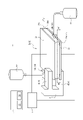
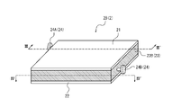
- FIG. 1 is a schematic diagram showing a schematic configuration of a substance introduction device 1.
- FIG. 2 is a side view of the substance introduction device 1.
- the substance introduction device 1 includes a substance introduction unit 2A, a voltage applying section 3, a holding section 4, and a control section 5. As shown in FIG.
- the substance introduction unit 2A is used to introduce substances into cells by electroporation.
- the substance introduction unit 2A includes a first electrode 21, a second electrode 22, a housing portion 23A, and a port 24.
- the substance introduction unit 2A is removable from the substance introduction device 1.
- the substance introduction unit 2A is fixed to the substance introduction device 1 by being attached to the holding portion 4 of the substance introduction device 1 .
- the substance introduction unit 2A can be removed from the substance introduction device 1 and carried as a container containing the introduced cell suspension into which the substance has been introduced into the cells by electroporation. can.
- the substance introduction unit 2A may be formed integrally with the substance introduction device 1, and may not be removable from the substance introduction device 1.
- the first electrode 21 is an electrode having a substantially rectangular flat first electrode surface 21A.
- the first electrode 21 is a plate-like electrode.
- the shape of the first electrode 21 is not limited to a plate shape, and may be any shape having the first electrode surface 21A.
- the first electrode 21 is made of an electrically conductive material such as a metal or a conductive polymer.
- the second electrode 22 is an electrode having a substantially rectangular flat second electrode surface 22A.
- the second electrode 22 is a substantially rectangular plate-shaped electrode.
- the shape of the second electrode 22 is not limited to a plate shape, and may be any shape having a second electrode surface 22A.
- the second electrode 22 is made of an electrically conductive material, such as a metal or a conductive polymer.
- the first electrode surface 21A and the second electrode surface 22A are arranged to face each other. More specifically, the second electrode surface 22A faces the first electrode surface 21A in a direction perpendicular to the first electrode surface 21A. That is, the facing direction of the first electrode surface 21A and the second electrode surface 22A in the present embodiment is a vertical direction perpendicular to the first electrode surface 21A and the second electrode surface 22A.
- the facing direction of the first electrode surface 21A and the second electrode surface 22A may be simply referred to as the "facing direction".
- the first electrode surface 21A and the second electrode surface 22A have the same shape and overlap each other when viewed from the direction perpendicular to the first electrode surface 21A.
- the fact that the second electrode surface 22A faces the first electrode surface 21A in the direction perpendicular to the first electrode surface 21A means that when viewed from the direction perpendicular to the first electrode surface 21A, the first electrode surface 21A It is not limited to completely overlapping the second electrode surface 22A, and includes overlapping of at least a portion of the first electrode surface 21A and the second electrode surface 22A. Also, the first electrode surface 21A and the second electrode surface 22A may not have the same shape, and may have different sizes.
- the storage section 23A is configured to store a cell suspension containing cells and a substance to be introduced into the cells.
- the containing portion 23A has a channel 234 inside which can contain the cell suspension.
- the flow path 234 of the housing portion 23A has one or more turbulence generating structures. As a result, turbulence is generated in the cell suspension and the cell suspension is agitated by passing through the channel 234 between the time when the cell suspension is injected into the storage section 23A and before it is discharged. be. Therefore, the substance introduction unit 2A can improve the mixing state of the cells in the cell suspension and the substance to be introduced into the cells, and can more uniformly introduce the substance into the cells.
- Channel 234 may be, for example, a tubular channel formed of an electrically conductive material.
- a tubular flow path may be, for example, a flow path partitioned by the containing portion 23A itself formed of a conductive material, or a flow partitioned by embedding a liquid-feeding tube in the containing portion 23A. It can be a road.
- a portion of the housing portion 23A other than the flow path 234 may be hollow or may be filled with a conductive material.
- the housing portion 23A is arranged between the first electrode surface 21A and the second electrode surface 22A. Specifically, the housing portion 23A is in a state in which it can be sandwiched between the first electrode surface 21A and the second electrode surface 22A without leaving a gap between the outer surface thereof and the first electrode surface 21A and the second electrode surface 22A. are placed in More specifically, as shown in FIG. 2, in a state in which the storage section 23A is filled with the cell suspension, the storage section 23A has an upper surface 231 in contact with the first electrode surface 21A and a lower surface 232 in contact with the second electrode surface 22A.
- the housing portion 23A is positioned between the first electrode surface 21A and the second electrode surface 22A. are placed.
- the housing portion 23A is configured to be removable from the first electrode surface 21A and the second electrode surface 22A.
- the housing portion 23A is held by the holding portion 4 in a state of being sandwiched between the first electrode surface 21A and the second electrode surface 22A without being adhered or the like. By doing so, the accommodating portion 23A of the present embodiment can be removed from the first electrode surface 21A and the second electrode surface 22A.
- the container 23A is removed from the substance introduction device 1 and the first electrode 21 and the second electrode 22, which together constitute the substance introduction unit 2A, and the introduced cell suspension is removed.
- the accommodating portion 23A may be fixed to the first electrode surface 21A and the second electrode surface 22A by adhesion or the like, and may not be removable.
- the housing portion 23A is a flexible bag-like container made of a conductive material such as a conductive polymer.
- the conductive material is softer than the material of the first electrode 21 and the second electrode 22 so that the shape of the housing portion 23A is deformed by being sandwiched between the first electrode 21 and the second electrode 22 .
- the changeable shape of the accommodating portion 23A enables the change of the facing distance between the first electrode surface 21A and the second electrode surface 22A in the substance introduction unit 2A. For example, by pressing the surface of the first electrode 21 opposite to the first electrode surface 21A and the surface of the second electrode 22 opposite to the second electrode surface 22A, the shape of the accommodating portion 23A is deformed. Thus, the distance between the first electrode surface 21A and the second electrode surface 22A can be shortened. As a result, the distance between the first electrode surface 21A and the second electrode surface 22A is changed according to the type or amount of the cell suspension contained in the flow channel 234 of the containing portion 23A. A suitable distance can be used to
- the port 24 is a tubular member capable of injecting the cell suspension into the flow path 234 of the storage section 23A or discharging it from the flow path 234 of the storage section 23A.
- the port 24 is provided on a side surface 233 other than the upper surface 231 and the lower surface 232 of the housing portion 23A. This makes the port 24 less likely to interfere with electroporation.
- the port 24 has, for example, an open/close valve. In such a case, by opening the valve of the port 24, it is possible to inject the cell suspension into the channel 234 of the container 23A or release the cell suspension from the channel 234 of the container 23A.
- the ports 24 may include an injection port 24A and an ejection port 24B.
- the injection port 24A and the discharge port 24B are each provided with a check valve or the like to regulate the flow of the cell suspension flowing therein.
- the injection port 24A regulates the flow of the cell suspension in the direction of injecting the cell suspension into the channel 234 of the housing portion 23A.
- the injection port 24A may be connected to the pre-introduction bag 10 containing the cell suspension before electroporation by a liquid delivery tube.
- the discharge port 24B regulates the flow of the cell suspension in the direction of discharging the cell suspension from the channel 234 of the container 23A.
- the discharge port 24B may be connected to the introduced bag 11 containing the cell suspension after electroporation by means of a liquid delivery tube.
- the injection port 24A and the discharge port 24B are provided at positions on both sides of the upper surface 231 of the side surface 233 of the housing portion 23A in a plan view along the opposing direction.
- a cell suspension in which cells and a substance to be introduced into the cells are previously suspended in a buffer solution (buffer) is used, but the present invention is not limited to this.
- a cell suspension containing cells and a substance to be introduced into the cells may be mixed at the timing of pouring into the storage portion 23A, or may be poured into the storage portion 23A at different timings, and may be mixed in the storage portion 23A. may be mixed with
- the voltage applying section 3 applies a voltage between the first electrode surface 21A and the second electrode surface 22A.
- the voltage application unit 3 is not particularly limited as long as it can apply a voltage between the first electrode surface 21A and the second electrode surface 22A.
- the voltage application unit 3 may be, for example, a storage battery or a dry battery.
- the voltage application unit 3 may be configured to receive power supply from the external power supply, for example, by including an adapter or the like for receiving power supply from the external power supply.
- the voltage application unit 3 is connected to the first electrode 21 and the second electrode 22 by a lead wire or the like so as to be able to supply power, as indicated by solid lines in FIG.
- the voltage application unit 3 applies a predetermined voltage between the first electrode 21 and the second electrode 22, thereby applying a voltage to the cell suspension accommodated in the flow channel 234 of the accommodation unit 23A, Substances are introduced into cells by electroporation.
- the cell suspension is injected from the injection port 24A into the channel 234 of the housing portion 23A.
- the voltage application section 3 operates the first electrode surface 21A and the second electrode surface with the injection port 24A and the discharge port 24B closed.
- a voltage is applied between 22A.
- the cell suspension is discharged from discharge port 24B.
- air or a buffer solution may be injected into the channel 234 from the injection port 24A.
- the cell suspension in the channel 234 of the storage section 23A can be collected without leaving any residue.
- the voltage A voltage may be applied by the application unit 3 .
- the length of the flow path 234 of the storage section 23A may be designed according to the execution time of electroporation, the flow rate of the cell suspension, and the like.
- the holding part 4 holds the substance introduction unit 2A.
- the holding section 4 includes a first holding member 41 and a second holding member 42 .
- one of the first holding member 41 and the second holding member 42 supports one of the first electrode 21 and the second electrode 22 .
- the substance introduction unit 2 is held by the holding portion 4 .
- the second holding member 42 is configured to support the substance introduction unit 2 from the side of the second electrode 22 opposite to the second electrode surface 22A. That is, in this embodiment, the substance introduction unit 2 is held by the holding section 4 by being supported by the second holding member 42 of the holding section 4 .
- the holding part 4 presses the first electrode 21 from the surface opposite to the first electrode surface 21A of the first electrode 21 with the first holding member 41, and presses the second electrode 22 with the second holding member 42.
- the substance introduction unit 2A can be sandwiched by pressing the second electrode 22 from the surface opposite to the second electrode surface 22A.
- the holding section 4 may have any structure capable of holding the substance introduction unit 2A.
- the holding part 4 is made of an insulating material such as plastic, glass, silicon, or quartz.
- the control unit 5 includes a memory 51 and a processor 52, for example.
- a computer such as an electroporator, a personal computer, a smart phone, or a tablet terminal may be used.
- the memory 51 is, for example, a semiconductor memory, a magnetic memory, an optical memory, or the like.
- the memory 51 functions, for example, as a main memory device, an auxiliary memory device, or a cache memory.
- the memory 51 stores arbitrary information used for the operation of the substance introduction device 1 .
- the memory 51 stores system programs, application programs, embedded software, and the like.
- the processor 52 may be, for example, a general-purpose processor such as a CPU (Central Processing Unit), or a dedicated processor specialized for specific processing.
- the processor 52 may include, for example, a dedicated circuit such as an FPGA (Field-Programmable Gate Array) or an ASIC (Application Specific Integrated Circuit).
- the control unit 5 is communicably connected to the voltage applying unit 3 by wire or wirelessly, as indicated by the dashed line in FIG. Thereby, the control unit 5 controls components such as the voltage application unit 3 in order to realize the function of the substance introduction device 1 . Specifically, the control unit 5 can control the voltage application unit 3 to apply a predetermined voltage between the first electrode surface 21A and the second electrode surface 22A.
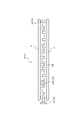
- FIG. 3 is a cross-sectional view of the substance introduction unit 2A taken along line I-I' shown in FIG. Specifically, FIG. 3 is a cross-sectional view of the substance introduction unit 2A shown in FIG. 1 cut along the line I-I' in the opposite direction.
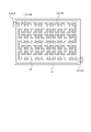
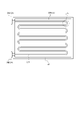
- FIG. 4 is a cross-sectional view along II-II' of the substance introduction unit 2A shown in FIG. Specifically, FIG. 4 is a cross-sectional view of the substance introduction unit 2A shown in FIG. 1 cut along II-II' in a direction orthogonal to the facing direction (a direction along the first electrode surface 21A in this embodiment). is.
- Channel 234 may be a tubular channel having one or more bends 235 as turbulence-generating structures. As the cell suspension passes through the bend 235, turbulence is generated and the cell suspension is agitated. This prevents uneven distribution of cells due to sedimentation of cells in the cell suspension, and the storage section 23A enables more uniform introduction of the substance to the cells. In addition, after electroporation, the container 23A increases the chances of contact between the cells with holes in the cell membrane and the substances to be introduced into the cells, thereby promoting the introduction of substances into the cells.
- the flow path 234 since the flow path 234 has the bent portion 235, the flow path 234 can be installed at a higher density in the housing portion 23A, and the length of the flow path 234 can be increased.
- the shape and size of the cross section of the channel 234 can be arbitrarily determined according to the amount and type of cell suspension to be processed in one electroporation, but for example, it is circular with a diameter of 1 mm to several mm. may Also, the volume of the entire channel 234 is arbitrarily determined according to the amount of cell suspension processed in one electroporation, and is, for example, 100 milliliters.
- the flow path 234 of the housing portion 23A has a bent portion 235A shown in a cross-sectional view along the facing direction as shown in FIG. and portion 235B.
- the bent portion 235A shown in FIG. 3 bends in the out-of-plane direction, which is the direction intersecting the first electrode surface 21A and the second electrode surface 22A.
- the bent portion 235B shown in FIG. 4 bends in the in-plane direction, which is the direction along the first electrode surface 21A and the second electrode surface 22A. That is, the flow path 234 of the housing portion 23A is three-dimensionally (three-dimensionally) curved.
- the flow path 234 of the housing portion 23A has either a bent portion 235A bent in the out-of-plane direction or a bent portion 235B bent in the in-plane direction, and is bent planarly (two-dimensionally).
- bent portion 235A and 235B when the bent portions 235A and 235B are not particularly distinguished, they will simply be collectively referred to as the bent portion 235.
- FIG. 1 when the bent portions 235A and 235B are not particularly distinguished, they will simply be collectively referred to as the bent portion 235.
- FIG. 5 shows a modification of the flow path 234 of the housing portion 23A shown in FIG.
- FIG. 5 is a cross-sectional view of the accommodating portion 23A at the same position as in FIG.
- channel 234 may be a plurality of straight channels connected via U-shaped bends 235 .
- the injection port 24A and the discharge port 24B may be provided in the same direction with respect to the accommodating portion 23A in plan view along the opposing direction.
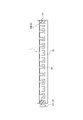
- FIG. 6 is a diagram showing a second modification of the flow path 234 of the housing portion 23A.
- one or more barriers 236 may be provided as turbulence generating structures in the flow path 234 of the housing portion 23A.
- barriers 236 may be provided to narrow the cross-section of a portion of channel 234 . This creates turbulence and agitates the cell suspension as it passes through the barrier 236, as indicated by the arrows in FIG. According to such a configuration, it is not necessary to provide the curved portion 235 in the flow path 234 in order to generate turbulence in the flow path 234, and the shape of the housing portion 23A can be designed more flexibly.
- the housing portion 23A can be formed into an elongated shape.
- the flow path 234 of the housing portion 23A may have both the curved portion 235 and the barrier 236 as the turbulence generating structure.
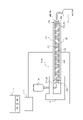
- FIG. 7 is a schematic diagram showing a schematic configuration of the substance introduction unit 2B.
- FIG. 8 is a cross-sectional view along III-III' of the substance introduction unit 2B shown in FIG. Specifically, FIG. 8 is a cross-sectional view of the substance introduction unit 2B shown in FIG. 7 taken along line III-III' in the opposite direction.
- FIG. 9 is a cross-sectional view of the substance introduction unit 2B taken along IV-IV' shown in FIG. Specifically, FIG. 9 is a cross-sectional view of the substance introduction unit 2B shown in FIG.
- the substance introduction unit 2B differs from the substance introduction unit 2A in that the containing portion 23B is not a bag-like container.
- the substance introduction unit 2B will be described below, focusing on the differences from the substance introduction unit 2A. Parts having the same configuration as the substance introduction unit 2A are denoted by the same reference numerals.
- the substance introduction units 2A and 2B when the substance introduction units 2A and 2B are not particularly distinguished, they will simply be collectively referred to as the substance introduction unit 2.
- FIG. when the accommodating portions 23A and 23B are not particularly distinguished, they are simply referred to collectively as the accommodating portion 23. As shown in FIG.
- the substance introduction unit 2B includes a first electrode 21, a second electrode 22, a housing portion 23B, and a port 24.
- the substance introduction unit 2B may be removable from the substance introduction device 1, like the substance introduction unit 2A. As a result, after electroporation, the substance introduction unit 2B can be removed from the substance introduction device 1 and carried as a container containing the introduced cell suspension.
- the accommodating portion 23B is arranged between the first electrode surface 21A of the first electrode 21 and the second electrode surface 22A of the second electrode 22.
- the housing portion 23B is an insulating material that surrounds the sides of the space sandwiched between the first electrode surface 21A and the second electrode surface 22A. It has sidewalls 237 formed of.
- the insulating material may be, for example, plastic, glass, silicon, or quartz.
- At least the side wall 237 of the housing portion 23B is hard enough to stand on its own even under the weight of the first electrode 21 and the second electrode 22, unlike the side wall of the flexible bag-shaped housing portion 23A. Constructed of materials.
- the side wall 237 is fixed to the first electrode surface 21A and the second electrode surface 22A by adhesion or the like. Thereby, the distance between the first electrode surface 21A and the second electrode surface 22A is always kept constant.
- the port 24 is provided on the side wall 237 of the housing portion 23B. This makes the port 24 less likely to interfere with electroporation.
- Ports 24 may include an injection port 24A and an ejection port 24B, similar to substance introduction unit 2A.
- the injection port 24A and the discharge port 24B are provided at positions on both sides of the side wall 237 of the accommodating portion 23B on both sides of the first electrode surface 21A in plan view along the opposing direction.
- the containing portion 23B defines therein a channel 234 capable of containing a cell suspension containing cells and substances.
- the channel 234 of the housing portion 23B has one or more turbulence generating structures. As shown in FIG. 9, the channel 234 of the housing portion 23B continues from the injection port 24A to the discharge port 24B.
- the channel 234 may be configured by, for example, a liquid-sending tube made of a conductive material and embedded in the housing portion 23B.
- a portion of the housing portion 23B other than the flow path 234 may be hollow or may be filled with a conductive material.
- the shape and structure of the channel 234 of the accommodating portion 23B may be the shape and structure of the channel 234 of the substance introduction unit 2A described above, or the shape and structure of the modified example of the channel 234 .
- the substance introduction device 1 is a substance introduction device 1 that introduces substances into cells by electroporation, and includes the substance introduction unit 2 and the voltage application section 3 .
- the substance introduction unit 2 is arranged between a first electrode surface 21A and a second electrode surface 22A which are arranged to face each other, and between the first electrode surface 21A and the second electrode surface 22A. and a storage section 23 that defines a channel 234 that can store turbid liquid.
- the channel 234 of the housing portion 23 has one or more turbulence generating structures.
- the voltage applying section 3 can apply a voltage between the first electrode surface 21A and the second electrode surface 22A.
- the substance introduction device 1 can improve the mixing state of the cells in the cell suspension and the substance to be introduced into the cells, thereby enabling more uniform introduction of the substance into the cells. Therefore, the substance introduction device 1 can improve the usefulness of techniques for introducing substances into cells by electroporation.
- the substance introduction unit 2 is preferably removable from the substance introduction device 1. According to such a configuration, after electroporation, the substance introduction unit 2 can be removed from the substance introduction device 1 and carried as a container containing the introduced cell suspension.
- the substance introduction unit 2 is a substance introduction unit 2 used for introducing substances into cells by electroporation, and includes a first electrode surface 21A and a second electrode surface 22A that are arranged to face each other, A storage section 23 that is arranged between the first electrode surface 21A and the second electrode surface 22A and defines a flow path 234 that can store a cell suspension containing cells and substances.
- channel 234 has one or more turbulation structures therein. According to such a configuration, turbulence is generated in the cell suspension by passing through the channel 234 from the time the cell suspension is injected into the storage section 23 to the time it is discharged. is stirred.
- the substance introduction unit 2 can improve the mixing state of the cells in the cell suspension and the substance to be introduced into the cells, enabling more uniform introduction of the substance into the cells. Therefore, the substance introduction unit 2 can improve the usefulness of techniques for introducing substances into cells by electroporation.
- the channel 234 is preferably a tubular channel 234 having one or more bent portions 235 as the turbulence generating structure. According to such a configuration, the substance introduction unit 2 can install the flow paths 234 at a higher density in the storage section 23, and the length of the flow paths 234 provided in the storage section 23A can be increased.
- the channel 234 is preferably provided with one or more barriers 236 as a turbulence generating structure. According to such a configuration, the substance introduction unit 2 does not necessarily need to provide the channel 234 with the curved portion 235 in order to generate turbulent flow in the channel 234, and the shape of the accommodation section 23 can be designed more flexibly. can be done.
- the storage section 23 includes an injection port 24A that defines the flow of the cell suspension in the direction of injecting the cell suspension into the flow channel 234 of the storage section 23; and a discharge port 24B that regulates the flow of the cell suspension in the direction of discharging from the channel 234 of the container 23 .
- an injection port 24A that defines the flow of the cell suspension in the direction of injecting the cell suspension into the flow channel 234 of the storage section 23
- a discharge port 24B that regulates the flow of the cell suspension in the direction of discharging from the channel 234 of the container 23 .
- the accommodating portion 23A is preferably a flexible bag-like accommodating portion 23A made of a conductive material. According to such a configuration, by deforming the accommodating portion 23A, the distance between the first electrode surface 21A and the second electrode surface 22A can be changed to an appropriate distance for performing electroporation. .
- the storage section 23A is removable from the substance introduction unit 2. According to such a configuration, after electroporation, the container 23A can be removed from the substance introduction device 1 and the substance introduction unit 2 and carried as a container containing the introduced cell suspension.
- the substance introduction device 1 is provided with the control section 5, and the control section 5 controls the voltage application section 3.
- the substance introduction device 1 may not include the control section 5 and the voltage application section 3 may be controlled by a human. As a result, the manufacturing cost of the substance introduction device 1 can be suppressed, and the substance introduction device 1 can be provided at a low price.
- substance introduction device 2 (2A, 2B) substance introduction unit 21 first electrode 21A first electrode surface 22 second electrode 22A second electrode surface 23 (23A, 23B) housing portion 231 upper surface 232 lower surface 233 side surface 234 channel 235 ( 235A, 235B) bent portion 236 barrier 237 side wall 24 port 24A injection port 24B discharge port 3 voltage application section 4 holding section 41 first holding member 42 second holding member 5 control section 51 memory 52 processor 10 pre-introduction bag 11 already introduced bag
Landscapes
- Life Sciences & Earth Sciences (AREA)
- Chemical & Material Sciences (AREA)
- Engineering & Computer Science (AREA)
- Bioinformatics & Cheminformatics (AREA)
- Health & Medical Sciences (AREA)
- Wood Science & Technology (AREA)
- Biotechnology (AREA)
- Organic Chemistry (AREA)
- Zoology (AREA)
- Microbiology (AREA)
- Sustainable Development (AREA)
- Biomedical Technology (AREA)
- Biochemistry (AREA)
- General Engineering & Computer Science (AREA)
- General Health & Medical Sciences (AREA)
- Genetics & Genomics (AREA)
- Medicinal Chemistry (AREA)
- Apparatus Associated With Microorganisms And Enzymes (AREA)
Abstract
本開示に係る物質導入装置は、エレクトロポレーションにより細胞に物質を導入する物質導入装置であって、物質導入ユニットと、電圧印加部と、を備える。物質導入ユニットは、対向して配置される第1電極面及び第2電極面と、第1電極面と第2電極面との間に配置され、細胞及び物質を含む細胞懸濁液を収容可能な流路を内部に区画する収容部と、を備え、流路は、1つ以上の乱流発生構造を有し、電圧印加部は、第1電極面及び第2電極面の間に電圧を印加可能である。
Description
本開示は、物質導入装置及び物質導入ユニットに関する。
従来、エレクトロポレーションによりDNA等の物質を導入した細胞を大量に獲得する技術が知られている。例えば、特許文献1には、エレクトロポレーションを実施するためのウェルを複数備えたエレクトロポレーション装置が開示されている。
しかしながら、従来の装置では、エレクトロポレーションを実施するためのウェル又はキュベット等の容器の数を増やすことで、1回の処理対象とする細胞懸濁液の総量を増やすことができる反面、複数の容器のそれぞれに、細胞懸濁液を添加し、エレクトロポレーション実施後に、それぞれの容器から導入済み細胞懸濁液を回収する必要があった。そのため、エレクトロポレーションの実施に伴う操作又は作業が煩雑になってしまう。また、細胞懸濁液における細胞と細胞に導入する物質の混合状態にばらつきがあると、導入効率が低下してしまう。したがって、細胞懸濁液における細胞と細胞に導入する物質の混合状態にばらつきを生じにくくしつつ、エレクトロポレーションの実施に伴う操作又は作業が煩雑にならないようにすることで、エレクトロポレーションにより細胞に物質を導入する技術の有用性の向上が求められている。
かかる事情に鑑みてなされた本開示の目的は、エレクトロポレーションにより細胞に物質を導入する技術の有用性を向上させる、物質導入装置及び物質導入ユニットを提供することにある。
本開示の一実施形態に係る物質導入装置は、エレクトロポレーションにより細胞に物質を導入する物質導入装置であって、物質導入ユニットと、電圧印加部と、を備え、前記物質導入ユニットは、対向して配置される第1電極面及び第2電極面と、前記第1電極面と前記第2電極面との間に配置され、前記細胞及び前記物質を含む細胞懸濁液を収容可能な流路を内部に区画する収容部と、を備え、前記流路は、1つ以上の乱流発生構造を有し、前記電圧印加部は、前記第1電極面及び前記第2電極面の間に電圧を印加可能である。
本開示の一実施形態に係る物質導入装置では、前記物質導入ユニットは、前記物質導入装置から取り外し可能であることが好ましい。
本開示の一実施形態に係る物質導入ユニットは、エレクトロポレーションによる細胞への物質の導入に用いられる物質導入ユニットであって、対向して配置される第1電極面及び第2電極面と、前記第1電極面と前記第2電極面との間に配置され、前記細胞及び前記物質を含む細胞懸濁液を収容可能な流路を内部に区画する収容部と、を備え、前記流路は、1つ以上の乱流発生構造を有する。
本開示の一実施形態に係る物質導入ユニットでは、前記流路は、乱流発生構造として1つ以上の屈曲部分を有する管状の流路であることが好ましい。
本開示の一実施形態に係る物質導入ユニットでは、前記流路には、乱流発生構造として1つ以上の障壁が設けられていることが好ましい。
本開示の一実施形態に係る物質導入ユニットでは、前記収容部は、前記細胞懸濁液を前記流路に注入する方向に前記細胞懸濁液の流れを規定する注入ポートと、前記細胞懸濁液を前記流路から放出する方向に前記細胞懸濁液の流れを規定する放出ポートと、を含むことが好ましい。
本開示の一実施形態に係る物質導入ユニットでは、前記収容部は、導電性材料で形成された、可撓性を有する袋状の収容部であることが好ましい。
本開示の一実施形態に係る物質導入ユニットでは、前記収容部は、前記物質導入ユニットから取り外し可能であることが好ましい。
本開示に係る物質導入装置及び物質導入ユニットによれば、エレクトロポレーションにより細胞に物質を導入する技術の有用性を向上させることができる。
以下、本開示の実施形態に係る物質導入装置1について、図面を参照して説明する。
各図中、同一又は相当する部分には、同一符号を付している。本実施形態の説明において、同一又は相当する部分については、説明を適宜省略又は簡略化する。
本開示の実施形態に係る物質導入装置1は、エレクトロポレーションにより細胞に物質を導入する。エレクトロポレーションは、細胞及び細胞に導入する物質を含む細胞懸濁液に電気パルス等を印加することにより、細胞の細胞膜に穴をあけ、物質を細胞内に導入する方法である。エレクトロポレーションは、電気穿孔法とも呼ばれる。本実施形態では、細胞懸濁液は、例えば、動物細胞又は大腸菌等の細胞と、遺伝子、デオキシリボ核酸(DNA)、リボ核酸(RNA)、核酸、タンパク質、低分子化合物、脂質分子、又はリポソーム等の物質とを、緩衝液(バッファ)に懸濁させたものである。
はじめに、図1及び図2を参照して、本開示の一実施形態に係る物質導入装置1について説明する。図1は、物質導入装置1の概略構成を示す、概略図である。図2は、物質導入装置1の側面図である。図1に示されるように、物質導入装置1は、物質導入ユニット2Aと、電圧印加部3と、保持部4と、制御部5とを備えている。
物質導入ユニット2Aは、エレクトロポレーションによる細胞への物質の導入に用いられる。物質導入ユニット2Aは、第1電極21と、第2電極22と、収容部23Aと、ポート24と、を備えている。物質導入ユニット2Aは、物質導入装置1から取り外し可能である。より具体的には、図1に示されるように、物質導入ユニット2Aは、物質導入装置1の保持部4に取り付けられることで、物質導入装置1に固定される。これにより、エレクトロポレーション実施後、物質導入ユニット2Aを、物質導入装置1から取り外して、エレクトロポレーションにより細胞に物質が導入された導入済みの細胞懸濁液が収容された容器として持ち運ぶことができる。しかしながら、物質導入ユニット2Aは、物質導入装置1と一体として形成されていてもよく、物質導入装置1から取り外し可能でなくてもよい。
第1電極21は、略矩形の平坦な第1電極面21Aを有する電極である。本実施形態では、第1電極21は、板状の電極である。ただし、第1電極21の形状は、板状に限られず、第1電極面21Aを有する任意の形状とされてもよい。第1電極21は、例えば、金属又は導電性ポリマー等、通電可能な材料で形成される。
第2電極22は、略矩形の平坦な第2電極面22Aを有する電極である。本実施形態では、第2電極22は、略矩形の板状の電極である。ただし、第2電極22の形状は、板状に限られず、第2電極面22Aを有する任意の形状とされてもよい。第2電極22は、例えば、金属又は導電性ポリマー等、通電可能な材料で形成される。
第1電極面21A及び第2電極面22Aは、対向して配置されている。より具体的に、第2電極面22Aは、第1電極面21Aに対して垂直方向において第1電極面21Aと対向する。すなわち、本実施形態での第1電極面21A及び第2電極面22Aの対向方向は、第1電極面21A及び第2電極面22Aに対して垂直な垂直方向である。以下、説明の便宜上、第1電極面21A及び第2電極面22Aの対向方向を、単に「対向方向」と記載する場合がある。本実施形態では、第1電極面21Aと第2電極面22Aは、同じ形状であって、第1電極面21Aに対して垂直方向にから見て、互いに重複している。ただし、第2電極面22Aが第1電極面21Aに対して垂直方向において第1電極面21Aと対向することは、第1電極面21Aに対して垂直方向から見て、第1電極面21Aと第2電極面22Aとが完全に重なっていることに限られず、第1電極面21A及び第2電極面22Aの少なくとも一部が重なっていることも含まれる。また、第1電極面21Aと第2電極面22Aとは、互いに同一の形状でなくてもよく、異なる大きさであってもよい。
収容部23Aは、細胞と細胞に導入する物質とを含む細胞懸濁液を収容するように構成されている。具体的には、図2に示されるように、収容部23Aは、細胞懸濁液を収容可能な流路234を内部に区画している。収容部23Aの流路234は、1つ以上の乱流発生構造を有する。これにより、細胞懸濁液が収容部23Aに注入されてから放出されるまでに間に流路234を通過することで、細胞懸濁液に乱流が発生し、細胞懸濁液が攪拌される。そのため、物質導入ユニット2Aは、細胞懸濁液における細胞と細胞に導入する物質の混合状態を向上させることができ、より均一な細胞への物質の導入が可能になる。流路234は、例えば、導電性材料で形成された、管状の流路であってよい。このような管状の流路は、例えば、導電性材料で形成された収容部23A自体により区画される流路であってもよく、収容部23Aに送液チューブを埋設することにより区画される流路であってもよい。収容部23Aの流路234以外の部分は、中空とされていてもよく、或いは、導電性材料が充填されていてもよい。
収容部23Aは、第1電極面21Aと第2電極面22Aとの間に配置されている。具体的に、収容部23Aは、その外面と第1電極面21A及び第2電極面22Aそれぞれとの間に隙間を空けることなく、第1電極面21A及び第2電極面22Aにより挟み込み可能な状態で配置されている。より具体的には、図2に示されるように、収容部23Aは、細胞懸濁液を充填された状態において、第1電極面21Aと接する上面231と、第2電極面22Aと接する下面232とを有する。つまり、上面231及び第1電極面21Aが接触し、かつ、下面232及び第2電極面22Aが接触した状態で、収容部23Aは、第1電極面21Aと第2電極面22Aとの間に配置されている。本実施形態では、収容部23Aは、第1電極面21A及び第2電極面22Aと取り外し可能に構成されている。具体的には、収容部23Aは、第1電極面21A及び第2電極面22Aに接着等されることなく挟まれた状態で、保持部4に保持される。このようにすることで、本実施形態の収容部23Aは、第1電極面21A及び第2電極面22Aから取り外し可能である。かかる場合、エレクトロポレーション実施後、収容部23Aを、物質導入装置1、及び、物質導入ユニット2Aを共に構成する第1電極21及び第2電極22、から取り外して、導入済みの細胞懸濁液が収容された容器として持ち運ぶことができる。ただし、収容部23Aは、第1電極面21A及び第2電極面22Aと接着等により固定され、取り外し不可能とされてもよい。
収容部23Aは、導電性ポリマー等の導電性材料で形成された、可撓性を有する袋状の容器である。導電性材料は、第1電極21及び第2電極22により挟み込まれることで収容部23Aの形状が変形するように、第1電極21及び第2電極22の材料よりも柔らかい材料とされる。
収容部23Aの形状が変形可能であることによって、物質導入ユニット2Aにおいて、第1電極面21Aと第2電極面22Aとの間の対向距離が変更可能である。例えば、第1電極21の第1電極面21Aとは反対側の面と、第2電極22の第2電極面22Aとは反対側の面とを押圧することによって、収容部23Aの形状が変形して、第1電極面21Aと第2電極面22Aとの間の距離を短くすることができる。これにより、収容部23Aの流路234に収容される細胞懸濁液の種類又は量等に応じて、第1電極面21Aと第2電極面22Aとの間の距離を、エレクトロポレーションを実施するために適切な距離とすることができる。
ポート24は、細胞懸濁液を収容部23Aの流路234に注入し、或いは収容部23Aの流路234から放出可能な筒状部材である。ポート24は、収容部23Aの上面231及び下面232以外の側面233に設けられる。これにより、ポート24が、エレクトロポレーション実施の際に妨げとなりにくい。ポート24は、例えば、開閉式のバルブを備える。かかる場合、ポート24のバルブが開かれることで、収容部23Aの流路234への細胞懸濁液の注入、或いは収容部23Aの流路234からの細胞懸濁液の放出が可能となる。
ポート24には、注入ポート24Aと、放出ポート24Bと、が含まれていてもよい。注入ポート24A及び放出ポート24Bは、それぞれ逆止弁等を備え、内部を流れる細胞懸濁液の流れを規定する。注入ポート24Aは、細胞懸濁液を収容部23Aの流路234に注入する方向に細胞懸濁液の流れを規定する。注入ポート24Aは、エレクトロポレーションが行われる前の細胞懸濁液が収容されている導入前バッグ10と送液チューブで接続されてもよい。放出ポート24Bは、細胞懸濁液を収容部23Aの流路234から放出する方向に細胞懸濁液の流れを規定する。放出ポート24Bは、エレクトロポレーションが行われた後の細胞懸濁液が収容される導入済みバッグ11と送液チューブで接続されてもよい。これにより、収容部23Aへの細胞懸濁液の注入及び放出が容易になり、物質導入ユニット2Aの利便性が更に向上する。本実施形態では、注入ポート24A及び放出ポート24Bは、収容部23Aの側面233のうち、対向方向に沿って見た平面視で、上面231を挟む両側の位置に設けられている。なお、本実施形態では、細胞及び細胞に導入する物質が予め緩衝液(バッファ)に懸濁された細胞懸濁液が使用されるものとして説明するが、この限りではない。例えば、細胞を含む細胞懸濁液と、細胞に導入される物質とが、収容部23Aに流し込むタイミングで混合されてもよく、或いは、別々のタイミングで収容部23Aに流し込まれ、収容部23A内で混合されてもよい。
再び図1を参照して、電圧印加部3は、第1電極面21A及び第2電極面22Aの間に電圧を印加する。電圧印加部3は、第1電極面21A及び第2電極面22Aの間に電圧を印加可能であれば特に限定されない。電圧印加部3は、例えば、蓄電池又は乾電池等であってよい。また、電圧印加部3は、例えば、外部電源より電力供給を受けるためのアダプタ等を備え、外部電源から電力供給を受け付ける構成であってもよい。電圧印加部3は、第1電極21及び第2電極22と、図1に実線で示されるように、導線等により電力供給可能に接続されている。これにより、電圧印加部3が第1電極21及び第2電極22の間に所定の電圧を印加することで、収容部23Aの流路234に収容された細胞懸濁液に電圧が印加され、エレクトロポレーションにより細胞に物質が導入される。
本実施形態では、はじめに、細胞懸濁液が注入ポート24Aから収容部23Aの流路234に注入される。そして、収容部23Aの流路234に細胞懸濁液が収容されたのち、注入ポート24A及び放出ポート24Bが閉じられた状態で、電圧印加部3により、第1電極面21A及び第2電極面22Aの間に電圧が印加される。エレクトロポレーション終了後、細胞懸濁液は放出ポート24Bから放出される。その際に、注入ポート24Aから流路234にエアー又は緩衝液が注入されてもよい。これにより、収容部23Aの流路234内にある細胞懸濁液を残さずに回収することができる。ただし、注入ポート24A及び放出ポート24Bが閉じられず、注入ポート24Aから注入された細胞懸濁液が、放出ポート24Bから放出されるまで収容部23Aの流路234を流された状態で、電圧印加部3により電圧を印加されてもよい。かかる場合には、エレクトロポレーションの実行時間及び細胞懸濁液の流速等に応じて、収容部23Aの流路234の長さが設計されてもよい。
保持部4は、物質導入ユニット2Aを保持する。本実施形態では、保持部4は、第1保持部材41と、第2保持部材42と、を備える。保持部4において、第1保持部材41及び第2保持部材42の一方は、第1電極21及び第2電極22の一方を支持する。これにより、物質導入ユニット2は、保持部4に保持される。本実施形態では、第2保持部材42が、物質導入ユニット2を、第2電極22の第2電極面22Aと反対の面側から支持するように構成されている。すなわち、本実施形態では、物質導入ユニット2は、保持部4の第2保持部材42により支持されることにより、保持部4に保持される。保持部4は、第1保持部材41により、第1電極21の第1電極面21Aとは反対側の面から、第1電極21を押圧し、第2保持部材42により、第2電極22の第2電極面22Aとは反対側の面から、第2電極22を押圧して、物質導入ユニット2Aを挟み込むことができる。ただし、保持部4は、物質導入ユニット2Aを保持可能な任意の構造とされてもよい。保持部4は、例えばプラスチック、ガラス、シリコン、又はクォーツ等の絶縁材料で形成される。
制御部5は、例えば、メモリ51とプロセッサ52とを含む。制御部5として、例えば、エレクトロポレータ、パーソナルコンピュータ、スマートフォン、又はタブレット端末等のコンピュータが使用されてもよい。
メモリ51は、例えば半導体メモリ、磁気メモリ、又は光メモリ等である。メモリ51は、例えば主記憶装置、補助記憶装置、又はキャッシュメモリとして機能する。メモリ51は、物質導入装置1の動作に用いられる任意の情報を記憶する。例えば、メモリ51は、システムプログラム、アプリケーションプログラム、又は組み込みソフトウェア等を記憶する。
プロセッサ52は、例えば、CPU(Central Processing Unit)等の汎用のプロセッサ、又は特定の処理に特化した専用のプロセッサ等であってもよい。プロセッサ52は、例えば、FPGA(Field-Programmable Gate Array)、又はASIC(Application Specific Integrated Circuit)等の専用回路を含んでもよい。
制御部5は、図1に破線で示されるように、電圧印加部3と、有線又は無線により通信可能に接続されている。これによって、制御部5は、物質導入装置1の機能を実現させるために、電圧印加部3等の構成要素を制御する。具体的には、制御部5は、電圧印加部3を制御して、第1電極面21A及び第2電極面22Aの間に所定の電圧を印加することができる。
図3及び図4を参照して、第1の実施形態に係る収容部23Aの流路234についてより詳細に説明する。図3は、図1に示される物質導入ユニット2AのI-I’における断面図である。具体的には、図3は、図1に示される物質導入ユニット2Aを、I-I’において対向方向に切断した断面図である。図4は、図1に示される物質導入ユニット2AのII-II’における断面図である。具体的には、図4は、図1に示される物質導入ユニット2Aを、II-II’において対向方向に直交する方向(本実施形態では第1電極面21Aに沿う方向)に切断した断面図である。
図4に示されるように、収容部23Aの流路234は、注入ポート24Aから放出ポート24Bまで続いている。流路234は、乱流発生構造として1つ以上の屈曲部分235を有する管状の流路であってもよい。細胞懸濁液が屈曲部分235を通過する際に、乱流が発生し、細胞懸濁液が攪拌される。これにより、細胞懸濁液において細胞の沈殿等により細胞の分布が不均一になることを防ぎ、収容部23Aは、より均一な細胞への物質の導入が可能になる。また、エレクトロポレーション後に、収容部23Aは、細胞膜に穴が開いた細胞と細胞に導入する物質とが接触する機会が増え、細胞への物質の導入が促進される。さらに、流路234が屈曲部分235を有することで、収容部23A内により高密度で流路234を設置することができ、流路234の長さを長くすることができる。流路234の断面の形状及び大きさは、1回のエレクトロポレーションで処理される細胞懸濁液の量及び種類に応じて任意に定められるが、例えば、直径1mm~数mmの円形とされてもよい。また、流路234全体の容量は、1回のエレクトロポレーションで処理される細胞懸濁液の量に応じて任意に定められるが、例えば、100ミリリットルである。
収容部23Aの流路234は、図3に示されるように対向方向に沿う断面視において図示される屈曲部分235Aと、図4に示されるように対向方向に直交する断面視において図示される屈曲部分235Bとを有する。図3に示される屈曲部分235Aは、第1電極面21A及び第2電極面22Aと交差する方向である面外方向に屈曲する。また、図4に示される屈曲部分235Bは、第1電極面21A及び第2電極面22Aに沿う方向である面内方向に屈曲する。すなわち、収容部23Aの流路234は、立体的に(3次元的に)屈曲している。これにより、細胞懸濁液が流路234を通過する際に、より複雑な乱流が発生し、細胞懸濁液が攪拌されやすくなる。ただし、収容部23Aの流路234は、面外方向に屈曲する屈曲部分235A及び面内方向に屈曲する屈曲部分235Bのいずれか一方を有し、平面的に(2次元的に)屈曲していてもよい。以降の説明において、屈曲部分235A及び235Bを特に区別しない場合、単に、屈曲部分235と総称する。
収容部23Aの流路234が乱流発生構造として有する1つ以上の屈曲部分235の形状は、図3及び図4に示される形状に限られない。図5に、図4に示される収容部23Aの流路234の変形例を示す。図5は、収容部23Aの図4と同位置での断面図である。図5に示されるように、流路234は、複数の直線状の流路がU字形の屈曲部分235を介して連結されていてもよい。また、図5に示されるように、注入ポート24A及び放出ポート24Bは、対向方向に沿って見た平面視で、収容部23Aに対して同一方向に設けられていてもよい。
図6は、収容部23Aの流路234の第2の変形例を示す図である。図6に示されるように、収容部23Aの流路234には、乱流発生構造として1つ以上の障壁236が設けられていてもよい。図6に示されるように、障壁236は、流路234の一部の断面を狭めるように設けられていてもよい。これにより、図6に矢印で示されるように、細胞懸濁液が障壁236を通過する際に、乱流が発生し、細胞懸濁液が攪拌される。かかる構成によれば、流路234内で乱流を発生させるために必ずしも流路234に屈曲部分235を設ける必要がなく、収容部23Aの形状をより柔軟に設計することができる。例えば、直線状の流路234とすることで、収容部23Aを細長い形状とすることもできる。ただし、収容部23Aの流路234は、乱流発生構造として、屈曲部分235と障壁236との両方を備えていてもよい。
次に、図7、図8及び図9を参照して、物質導入ユニット2Aの変形例である物質導入ユニット2Bについて説明する。図7は、物質導入ユニット2Bの概略構成を示す、概略図である。図8は、図7に示される物質導入ユニット2BのIII-III’における断面図である。具体的には、図8は、図7に示される物質導入ユニット2Bを、III-III’において対向方向に切断した断面図である。図9は、図7に示される物質導入ユニット2BのIV-IV’における断面図である。具体的には、図9は、図7に示される物質導入ユニット2Bを、IV-IV’において対向方向と直交する方向に切断した断面図である。物質導入ユニット2Bは、収容部23Bが袋状の容器ではない点で、物質導入ユニット2Aと異なっている。以下に、物質導入ユニット2Aと異なる点を中心に物質導入ユニット2Bについて説明する。なお、物質導入ユニット2Aと同じ構成を有する部位には同じ符号を付す。以降の説明において、物質導入ユニット2A及び2Bを特に区別しない場合、単に、物質導入ユニット2と総称する。また、収容部23A及び23Bを特に区別しない場合、単に、収容部23と総称する。
図7に示されるように、物質導入ユニット2Bは、第1電極21と、第2電極22と、収容部23Bと、ポート24と、を備えている。物質導入ユニット2Bは、物質導入ユニット2Aと同様に物質導入装置1から取り外し可能であってもよい。これにより、エレクトロポレーション実施後、物質導入ユニット2Bを、物質導入装置1から取り外して、導入済みの細胞懸濁液が収容された容器として持ち運ぶことができる。
収容部23Bは、第1電極21の第1電極面21Aと第2電極22の第2電極面22Aとの間に配置されている。具体的には、図8及び図9に示されるように、収容部23Bは、第1電極面21Aと第2電極面22Aとの間に挟まれた空間の周囲の側方を囲む、絶縁材料で形成された側壁237を備えている。絶縁材料は、例えばプラスチック、ガラス、シリコン、又はクォーツ等であってもよい。少なくとも収容部23Bの側壁237は、上述した可撓性を有する袋状の収容部23Aの側壁と異なり、第1電極21及び第2電極22の自重が作用しても自立可能な程度の硬質な材料により構成されている。側壁237は、第1電極面21A及び第2電極面22Aに接着等により固定されている。これにより、第1電極面21Aと第2電極面22Aとの距離が常に一定に保たれる。
ポート24は、収容部23Bの側壁237に設けられる。これにより、ポート24が、エレクトロポレーション実施の際に妨げとなりにくい。ポート24には、物質導入ユニット2Aと同様に、注入ポート24Aと、放出ポート24Bと、が含まれていてもよい。本実施形態では、注入ポート24A及び放出ポート24Bは、収容部23Bの側壁237のうち、対向方向に沿って見た平面視で、第1電極面21Aを挟む両側の位置に設けられている。
収容部23Bは、細胞及び物質を含む細胞懸濁液を収容可能な流路234を内部に区画する。収容部23Bの流路234は、1つ以上の乱流発生構造を有する。図9に示されるように、収容部23Bの流路234は、注入ポート24Aから放出ポート24Bまで続いている。流路234は、例えば、収容部23Bに埋設されている、導電性材料で形成された送液チューブにより構成されてもよい。収容部23Bの流路234以外の部分は、中空とされていてもよく、或いは、導電性材料が充填されていてもよい。収容部23Bの流路234の形状及び構造は、上述した物質導入ユニット2Aの流路234の形状及び構造、或いは流路234の変形例の形状及び構造とされてもよい。
以上述べたように、本開示に係る物質導入装置1は、エレクトロポレーションにより細胞に物質を導入する物質導入装置1であって、物質導入ユニット2と、電圧印加部3と、を備える。物質導入ユニット2は、対向して配置される第1電極面21A及び第2電極面22Aと、第1電極面21Aと第2電極面22Aとの間に配置され、細胞及び物質を含む細胞懸濁液を収容可能な流路234を内部に区画する収容部23と、を備える。収容部23の流路234は、1つ以上の乱流発生構造を有する。電圧印加部3は、第1電極面21A及び第2電極面22Aの間に電圧を印加可能である。かかる構成によれば、細胞懸濁液が収容部23に注入されてから放出されるまでに間に流路234を通過することで、細胞懸濁液に乱流が発生し、細胞懸濁液が攪拌される。これにより、物質導入装置1は、細胞懸濁液における細胞と細胞に導入する物質の混合状態を向上させることができ、より均一な細胞への物質の導入が可能になる。したがって、物質導入装置1は、エレクトロポレーションにより細胞に物質を導入する技術の有用性を向上させることができる。
本開示に係る物質導入装置1では、物質導入ユニット2は、物質導入装置1から取り外し可能であることが好ましい。かかる構成によれば、エレクトロポレーション実施後、物質導入ユニット2を、物質導入装置1から取り外して、導入済みの細胞懸濁液が収容された容器として持ち運ぶことができる。
本開示に係る物質導入ユニット2は、エレクトロポレーションによる細胞への物質の導入に用いられる物質導入ユニット2であって、対向して配置される第1電極面21A及び第2電極面22Aと、第1電極面21Aと第2電極面22Aとの間に配置され、細胞及び物質を含む細胞懸濁液を収容可能な流路234を内部に区画する収容部23と、を備え、収容部23の流路234は、内部に1つ以上の乱流発生構造を有する。かかる構成によれば、細胞懸濁液が収容部23に注入されてから放出されるまでに間に流路234を通過することで、細胞懸濁液に乱流が発生し、細胞懸濁液が攪拌される。これにより、物質導入ユニット2は、細胞懸濁液における細胞と細胞に導入する物質の混合状態を向上させることができ、より均一な細胞への物質の導入が可能になる。したがって、物質導入ユニット2は、エレクトロポレーションにより細胞に物質を導入する技術の有用性を向上させることができる。
本開示に係る物質導入ユニット2では、流路234は、乱流発生構造として1つ以上の屈曲部分235を有する管状の流路234であることが好ましい。かかる構成によれば、物質導入ユニット2は、収容部23内により高密度で流路234を設置することができ、収容部23A内に設けられる流路234の長さを長くすることができる。
本開示に係る物質導入ユニット2では、流路234には、乱流発生構造として1つ以上の障壁236が設けられていることが好ましい。かかる構成によれば、物質導入ユニット2は、流路234内で乱流を発生させるために必ずしも流路234に屈曲部分235を設ける必要がなく、収容部23の形状をより柔軟に設計することができる。
本開示に係る物質導入ユニット2では、収容部23は、細胞懸濁液を収容部23の流路234に注入する方向に細胞懸濁液の流れを規定する注入ポート24Aと、細胞懸濁液を収容部23の流路234から放出する方向に細胞懸濁液の流れを規定する放出ポート24Bと、を含むことが好ましい。かかる構成によれば、収容部23の流路234への細胞懸濁液の注入及び放出が容易になり、物質導入ユニット2の利便性が更に向上する。
本開示に係る物質導入ユニット2Aでは、収容部23Aは、導電性材料で形成された、可撓性を有する袋状の収容部23Aであることが好ましい。かかる構成によれば、収容部23Aを変形させることで、第1電極面21Aと第2電極面22Aとの間の距離を、エレクトロポレーションを実施するために適切な距離に変更することができる。
本開示に係る物質導入ユニット2Aでは、収容部23Aは、物質導入ユニット2から取り外し可能であることが好ましい。かかる構成によれば、エレクトロポレーション実施後、収容部23Aを、物質導入装置1及び物質導入ユニット2から取り外して、導入済みの細胞懸濁液が収容された容器として持ち運ぶことができる。
本開示を諸図面及び実施例に基づき説明してきたが、当業者であれば本開示に基づき種々の変形及び修正を行うことが可能であることに注意されたい。したがって、これらの変形及び修正は本開示の範囲に含まれることに留意されたい。例えば、各手段又は各ステップ等に含まれる機能等は論理的に矛盾しないように再配置可能であり、複数の手段又はステップ等を1つに組み合わせたり、或いは分割したりすることが可能である。
例えば、上述した実施形態において、物質導入装置1が制御部5を備え、制御部5により電圧印加部3が制御されるものとして説明された。しかしながら、物質導入装置1は、制御部5を備えずに、人間により、電圧印加部3が制御されてもよい。これにより、物質導入装置1の製造コストを抑え、物質導入装置1を安価で提供することができる。
1 物質導入装置
2(2A、2B) 物質導入ユニット
21 第1電極
21A 第1電極面
22 第2電極
22A 第2電極面
23(23A、23B) 収容部
231 上面
232 下面
233 側面
234 流路
235(235A、235B) 屈曲部分
236 障壁
237 側壁
24 ポート
24A 注入ポート
24B 放出ポート
3 電圧印加部
4 保持部
41 第1保持部材
42 第2保持部材
5 制御部
51 メモリ
52 プロセッサ
10 導入前バッグ
11 導入済みバッグ
2(2A、2B) 物質導入ユニット
21 第1電極
21A 第1電極面
22 第2電極
22A 第2電極面
23(23A、23B) 収容部
231 上面
232 下面
233 側面
234 流路
235(235A、235B) 屈曲部分
236 障壁
237 側壁
24 ポート
24A 注入ポート
24B 放出ポート
3 電圧印加部
4 保持部
41 第1保持部材
42 第2保持部材
5 制御部
51 メモリ
52 プロセッサ
10 導入前バッグ
11 導入済みバッグ
Claims (8)
- エレクトロポレーションにより細胞に物質を導入する物質導入装置であって、
物質導入ユニットと、
電圧印加部と、を備え、
前記物質導入ユニットは、
対向して配置される第1電極面及び第2電極面と、
前記第1電極面と前記第2電極面との間に配置され、前記細胞及び前記物質を含む細胞懸濁液を収容可能な流路を内部に区画する収容部と、を備え、
前記流路は、1つ以上の乱流発生構造を有し、
前記電圧印加部は、前記第1電極面及び前記第2電極面の間に電圧を印加可能である、物質導入装置。 - 前記物質導入ユニットは、前記物質導入装置から取り外し可能である、請求項1に記載の物質導入装置。
- エレクトロポレーションによる細胞への物質の導入に用いられる物質導入ユニットであって、
対向して配置される第1電極面及び第2電極面と、
前記第1電極面と前記第2電極面との間に配置され、前記細胞及び前記物質を含む細胞懸濁液を収容可能な流路を内部に区画する収容部と、を備え、
前記流路は、1つ以上の乱流発生構造を有する、物質導入ユニット。 - 前記流路は、乱流発生構造として1つ以上の屈曲部分を有する管状の流路である、請求項3に記載の物質導入ユニット。
- 前記流路には、乱流発生構造として1つ以上の障壁が設けられている、請求項3又は4に記載の物質導入ユニット。
- 前記収容部は、
前記細胞懸濁液を前記流路に注入する方向に前記細胞懸濁液の流れを規定する注入ポートと、
前記細胞懸濁液を前記流路から放出する方向に前記細胞懸濁液の流れを規定する放出ポートと、
を含む、請求項3から5のいずれか一項に記載の物質導入ユニット。 - 前記収容部は、導電性材料で形成された、可撓性を有する袋状の収容部である、請求項3から6のいずれか一項に記載の物質導入ユニット。
- 前記収容部は、前記物質導入ユニットから取り外し可能である、請求項7に記載の物質導入ユニット。
Priority Applications (1)
| Application Number | Priority Date | Filing Date | Title |
|---|---|---|---|
| JP2023506939A JPWO2022196331A1 (ja) | 2021-03-18 | 2022-02-28 |
Applications Claiming Priority (2)
| Application Number | Priority Date | Filing Date | Title |
|---|---|---|---|
| JP2021044972 | 2021-03-18 | ||
| JP2021-044972 | 2021-03-18 |
Publications (1)
| Publication Number | Publication Date |
|---|---|
| WO2022196331A1 true WO2022196331A1 (ja) | 2022-09-22 |
Family
ID=83321452
Family Applications (1)
| Application Number | Title | Priority Date | Filing Date |
|---|---|---|---|
| PCT/JP2022/008432 WO2022196331A1 (ja) | 2021-03-18 | 2022-02-28 | 物質導入装置及び物質導入ユニット |
Country Status (2)
| Country | Link |
|---|---|
| JP (1) | JPWO2022196331A1 (ja) |
| WO (1) | WO2022196331A1 (ja) |
Citations (3)
| Publication number | Priority date | Publication date | Assignee | Title |
|---|---|---|---|---|
| JP2017529875A (ja) * | 2014-09-15 | 2017-10-12 | アルキマル, アクティーゼルスカブ | 酵素処理プラントおよび酵素処理方法 |
| JP2018506965A (ja) * | 2015-01-07 | 2018-03-15 | インディー.インコーポレイテッド | 機械的及び流体力学的マイクロ流体形質移入の方法ならびにそのための装置 |
| JP2021501608A (ja) * | 2017-11-02 | 2021-01-21 | インディー.プロプライエタリー リミテッドIndee.Pty.Ltd. | 細胞内送達及びそのための方法 |
-
2022
- 2022-02-28 WO PCT/JP2022/008432 patent/WO2022196331A1/ja active Application Filing
- 2022-02-28 JP JP2023506939A patent/JPWO2022196331A1/ja active Pending
Patent Citations (3)
| Publication number | Priority date | Publication date | Assignee | Title |
|---|---|---|---|---|
| JP2017529875A (ja) * | 2014-09-15 | 2017-10-12 | アルキマル, アクティーゼルスカブ | 酵素処理プラントおよび酵素処理方法 |
| JP2018506965A (ja) * | 2015-01-07 | 2018-03-15 | インディー.インコーポレイテッド | 機械的及び流体力学的マイクロ流体形質移入の方法ならびにそのための装置 |
| JP2021501608A (ja) * | 2017-11-02 | 2021-01-21 | インディー.プロプライエタリー リミテッドIndee.Pty.Ltd. | 細胞内送達及びそのための方法 |
Also Published As
| Publication number | Publication date |
|---|---|
| JPWO2022196331A1 (ja) | 2022-09-22 |
Similar Documents
| Publication | Publication Date | Title |
|---|---|---|
| Kar et al. | Single-cell electroporation: current trends, applications and future prospects | |
| Zimmerman | Electrochemical microfluidics | |
| JP4953044B2 (ja) | 脂質二重膜の形成方法およびその装置 | |
| US8241477B2 (en) | Double chamber tank for horizontal gel electrophoresis | |
| US20030087292A1 (en) | Methods and systems for promoting interactions between probes and target molecules in fluid in microarrays | |
| EP2202510B1 (en) | Electrophoresis apparatus for simultaneous loading of multiple samples | |
| ES2799422T3 (es) | Dispositivos y métodos de diagnóstico y preparación de muestras | |
| JP5299817B2 (ja) | 経皮吸収製剤の拡散測定装置 | |
| JP3605102B2 (ja) | 液体混合装置 | |
| SE1050168A1 (sv) | Ett system för elektrokinetisk flödesteknik | |
| JPWO2015079510A1 (ja) | 電流計測装置、電流計測方法、及び電流計測キット | |
| CN113136333B (zh) | 细胞转染系统及方法 | |
| WO2022196331A1 (ja) | 物質導入装置及び物質導入ユニット | |
| Sun et al. | Bubble-enhanced ultrasonic microfluidic chip for rapid DNA fragmentation | |
| WO2008051169A1 (en) | Tip electrode chamber for small volume electroporation | |
| US20190338235A1 (en) | Method and Device for Exosomes Electroporation | |
| JP4809687B2 (ja) | 生体関連物質検出用反応装置 | |
| Chen et al. | Ion channel electrophysiology via integrated planar patch‐clamp chip with on‐demand drug exchange | |
| JP2009115755A (ja) | 浸透圧ポンプを用いた送液駆動機構および該送液駆動機構を有するマイクロチップ | |
| Zhang et al. | Capacitive sensing for monitoring of microfluidic protocols using nanoliter dispensing and acoustic mixing | |
| JP4473007B2 (ja) | ハイブリダイゼーション方法 | |
| JP2022144114A (ja) | 物質導入装置 | |
| CN208908104U (zh) | 基于b-z振荡反应脉冲电池动力学研究的实验教学装置 | |
| JP2008209281A (ja) | 分析システム、並びにこれに用いるマイクロ化学チップ及び液駆動方法 | |
| JP2022144109A (ja) | 物質導入装置及び物質導入ユニット |
Legal Events
| Date | Code | Title | Description |
|---|---|---|---|
| 121 | Ep: the epo has been informed by wipo that ep was designated in this application |
Ref document number: 22771085 Country of ref document: EP Kind code of ref document: A1 |
|
| ENP | Entry into the national phase |
Ref document number: 2023506939 Country of ref document: JP Kind code of ref document: A |
|
| NENP | Non-entry into the national phase |
Ref country code: DE |
|
| 122 | Ep: pct application non-entry in european phase |
Ref document number: 22771085 Country of ref document: EP Kind code of ref document: A1 |