WO2022195961A1 - タイヤ - Google Patents
タイヤ Download PDFInfo
- Publication number
- WO2022195961A1 WO2022195961A1 PCT/JP2021/042851 JP2021042851W WO2022195961A1 WO 2022195961 A1 WO2022195961 A1 WO 2022195961A1 JP 2021042851 W JP2021042851 W JP 2021042851W WO 2022195961 A1 WO2022195961 A1 WO 2022195961A1
- Authority
- WO
- WIPO (PCT)
- Prior art keywords
- pattern
- tire
- area
- pattern region
- region
- Prior art date
- Legal status (The legal status is an assumption and is not a legal conclusion. Google has not performed a legal analysis and makes no representation as to the accuracy of the status listed.)
- Ceased
Links
Images

Classifications
-
- B—PERFORMING OPERATIONS; TRANSPORTING
- B60—VEHICLES IN GENERAL
- B60C—VEHICLE TYRES; TYRE INFLATION; TYRE CHANGING; CONNECTING VALVES TO INFLATABLE ELASTIC BODIES IN GENERAL; DEVICES OR ARRANGEMENTS RELATED TO TYRES
- B60C13/00—Tyre sidewalls; Protecting, decorating, marking, or the like, thereof
Definitions
- This disclosure relates to tires.
- the smooth surface of the side surface of the tire is decorated with minute unevenness (for example, see Japanese Patent Application Laid-Open No. 2019-099094).
- An object of the present disclosure is to provide a tire that can expand the range of expression of decorative parts.
- a first pattern region arranged on the outer surface of the tire and each formed by unevenness and a second pattern region having a higher brightness than the first pattern region, the first pattern region , and a plurality of the second pattern regions are arranged in the tire circumferential direction, and the area of the first pattern region and the area of the second pattern region increase toward one side in the tire circumferential direction.
- the first pattern area and the second pattern which are arranged adjacent to the first pattern area and have a higher brightness than the first pattern area, are arranged on the outer surface of the tire.
- a plurality of first pattern regions and second pattern regions are arranged in the tire circumferential direction, and the area of the first pattern region and the area of the second pattern region increase toward one side in the tire circumferential direction. there is Therefore, compared to the case where the outer surface of the tire is not decorated in this way, the expression of the decorative portion can be expanded.
- a tire according to a second aspect is the tire according to the first aspect, wherein at least a portion of the plurality of first pattern regions and the plurality of second pattern regions are partitioned by a smooth surface.
- At least some of the plurality of first pattern regions and the plurality of second pattern regions are partitioned by a smooth surface, so that at least some of the plurality of first pattern regions and the plurality of second pattern regions can further expand the range of expression of the decorative portion compared to the case where the is not partitioned by the smooth surface.
- a tire according to a third aspect is the tire according to the first aspect or the second aspect, wherein at least one of the plurality of first pattern regions and the plurality of second pattern regions has the same shape, and The area increases toward one side in the tire circumferential direction.
- At least one of the plurality of first pattern regions and the plurality of second pattern regions has the same shape, and by increasing the area toward one side in the tire circumferential direction, the plurality of first pattern regions and the plurality of At least one of the second pattern regions does not have the same shape and does not increase in area toward one side in the tire circumferential direction, the range of expression of the decorative portion can be further expanded.
- at least one of the plurality of first pattern regions and the plurality of second pattern regions has the same shape, and the area is increased toward one side in the tire circumferential direction, so that when the decorative portion is viewed, , the line of sight can be guided toward one side in the tire circumferential direction.
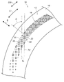
- FIG. 2 is a plan view showing decorative portions formed on the tire side portion of the tire according to the first embodiment; It is an enlarged plan view which shows the planar view shape of a 1st pattern area
- FIG. Arrow C shown in the drawing indicates the tire circumferential direction
- arrow CW indicates the clockwise direction
- arrow CCW indicates the counterclockwise direction
- arrow R indicates the tire radial direction.
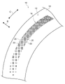
- a tire side portion 12 which is an example of the outer surface of the tire 10, is provided with a decorative portion 14 extending in the tire circumferential direction (arrow C direction).
- the decorative portion 14 has an arc shape when viewed from the axial direction of the tire 10, and is arranged at an arbitrary position in the tire circumferential direction.
- the tire side portion 12 other than the decorative portion 14 has a smooth surface like a normal tire.
- the portion of the tire side portion 12 that is formed as a smooth surface is appropriately referred to as a base surface 16 .
- the decorative portion 14 includes a plurality of first pattern regions 20 and second pattern regions 22 having different sizes and orientations.
- the first pattern area 20 and the second pattern area 22 are defined by the base surface (smooth surface) 16 over substantially the entire decorative portion 14 .
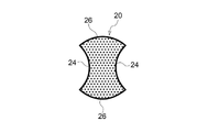
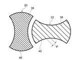
- the first pattern region 20 and the second pattern region 22 have the same outline shape in a plan view, but differ only in orientation, so the shape of the first pattern region 20 will be described as a representative.
- the first pattern region 20 includes a pair of arc recesses (inwardly protruding) 24 that face each other and a pair of arc protrusions (outwardly protruding) that are formed on both sides of the pair of arc recesses 24 and face each other. It has a shape configured with a convex) 26 .
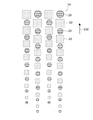
- the first pattern regions 20 and the second pattern regions 22 of the same size are alternately spaced apart on one line TL with respect to the tire circumferential direction, with their orientations changed by 90°. are placed.
- the line TL is inclined at an angle ⁇ with respect to the tire radial direction (arrow R direction).
- the size of the first pattern region 20 and the second pattern region 22 increases as they are arranged on the clockwise direction side (arrow CW direction side) as one side in the tire circumferential direction.
- the first pattern is arranged on another line TL′ arranged on the clockwise side compared to the first pattern region 20 and the second pattern region 22 arranged on the line TL.
- Region 20 and second pattern region 22 are large in size.
- the first pattern region 20 and the second pattern region 22 are exceptionally separated from each other without the base surface (smooth surface) 16 interposed therebetween. in contact with
- the first pattern area 20 has a lower lightness (L*) than the base surface 16 and appears blacker than the base surface 16 .
- the second pattern area 22 has a higher brightness than the first pattern area 20 and a lower brightness than the base surface 16 . That is, the brightness decreases in the order of the base surface 16, the second pattern region 22, and the first pattern region 20. Compared to the base surface 16, the second pattern region 22 appears black, and the first pattern region 20 appears black. It looks blacker than the second pattern region 22, and the first pattern region 20 looks the blackest.
- the surface of the tire side portion 12 is formed to have the first shape.
- a patterned area 20 and a second patterned area 22 may be formed.
- first pattern region 20 and the second pattern region 22 minute projections are formed that protrude from the base surface 16, so that the surfaces of the first pattern region 20 and the second pattern region 22 are uneven.
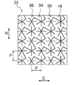
- first asterisk projections 34 and second asterisk projections 36 which are examples of projections, are formed in the first pattern region 20 and the second pattern region 22 to be similar to each other.
- the shapes of the first asterisk projection 34 and the second asterisk projection 36 are similar in their respective regions.
- the distance P between the first asterisk projection 34 and the second asterisk projection 36 adjacent to each other changes according to the similitude ratio.
- the shapes of the first asterisk projection 34 and the second asterisk projection 36 are similar in their respective regions. Accordingly, the shapes of the first asterisk projection 34 and the second asterisk projection 36 will be described below using the first pattern region 20 as an example.
- the first pattern area 20 has a plurality of first asterisk protrusions 34 and a plurality of second asterisk protrusions 36 projecting from the base surface 16 .
- the first asterisk projections 34 and the second asterisk projections 36 are alternately arranged in the tire circumferential direction and the tire radial direction.
- first asterisk projection 34 As shown in FIG. 3A, the first asterisk projections 34 are a plurality of projections extending in different directions from the center O1 as a base point when viewed from the direction perpendicular to the base surface 16 (rotational axis direction of the tire 10). , six extensions 34E are provided in this embodiment.
- the six extending portions 34E form an angle of 60° with each adjacent extending portion 34E.
- the first asterisk projection 34 has a shape in which six extending portions 34E extend radially from the center O1.
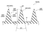
- the cross section in the direction orthogonal to the extending direction has a substantially isosceles triangle shape with a flat top surface 34C. That is, the first asterisk projection 34 has a top surface 34C and a pair of side surfaces 34D.
- the width of the top surface 34C (W1 in the drawing) is 0.02 mm
- the vertical angle of the first asterisk projection 34 (D1 in the drawing) is 26 degrees.
- the height (H in the drawing) of the first asterisk projection 34 is a predetermined value of 0.05 mm or more and 1.0 mm or less.
- the height of the protrusion is less than 0.05 [mm]
- it becomes difficult to form the protrusion and there is a possibility that the incident light may be attenuated and the brightness may not be lowered to the extent that it appears black. be.
- the height of the projection is set to 1.0 mm or less, the difference between the rigidity of the projection portion and the rigidity of the surrounding portion of the projection is reduced, thereby suppressing local stress concentration. ing.
- the height of the protrusions in the present embodiment and the dimensions such as the spacing (pitch) of the protrusions described later can be measured using, as an example, a one-shot 3D shape measuring machine VR-3000 series manufactured by Keyence Corporation. .
- the second asterisk projection 36 has a similar shape to the first asterisk projection 34 .
- the second asterisk projection 36 rotates the first asterisk projection 34 clockwise 90 degrees about the center O1 when viewed from a direction orthogonal to the base surface 16, and further, It has a shape in which the first asterisk projection 34 rotated 90 degrees around the center O1 is turned upside down. That is, the second asterisk projection 36 has six extending portions 36E extending in different directions from the center O2 as a base point, and each extending portion 36E has a top surface 36C and side surfaces 36D. ing.
- the first asterisk projections 34 and the second asterisk projections 36 are alternately arranged in the tire circumferential direction and the tire radial direction, filling the entire area.
- the distance between the center O1 and the center O2 (hereinafter referred to as the "distance P") is 0.1. It is set to a predetermined value equal to or greater than [mm] and equal to or less than 1.0 [mm]. If the interval P is less than 0.1 [mm], it will be difficult to form the protrusions. Furthermore, if the interval P is larger than 1.0 [mm], there is a possibility that the incident light cannot be attenuated and the lightness cannot be lowered to the extent that it looks black.
- first asterisk projections 34 and second asterisk projections 36 similar in shape to the first pattern region 20 are formed. , is lower than the density of the protrusions formed in the first pattern region 20 . As a result, the second pattern area 22 appears brighter than the first pattern area 20 .
- the first pattern regions 20 and the second pattern regions 22 are preferably arranged in three or more, more preferably five or more, in the tire circumferential direction.
- the incident light is reflected outward by the smooth outer surface that constitutes the base surface 16 .
- the first pattern area 20 and the second pattern area 22 the light incident on the first asterisk projection 34 and the second asterisk projection 36 hits the side surfaces 34D and 36D shown in FIG. The incident light is attenuated while being repeatedly reflected between the facing side surfaces 34D and 36D, and is reflected outward. Therefore, the first pattern area 20 and the second pattern area 22 appear black compared to the base surface 16 .
- the area occupied by the base surface 16 of the second pattern area 22 per unit area is smaller than the area occupied by the base surface 16 of the first pattern area 20 per unit area. and widen.
- the amount of light reflected outward from the second pattern area 22 is greater than the amount of light reflected outward from the first pattern area 20 . That is, the brightness of the second pattern area 22 is higher than that of the first pattern area 20 . In other words, the second patterned area 22 appears relatively lighter than the first patterned area 20 , and the first patterned area 20 appears relatively darker than the second patterned area 22 .
- the decorative portion 14 of the present embodiment includes a plurality of first pattern regions 20 and a plurality of second patterns arranged adjacent to the first pattern region 20 and having higher brightness than the first pattern region 20. 22 are provided, and the areas of the first pattern region 20 and the second pattern region 22 increase in the clockwise direction. For this reason, the decorative portion 14 of the present embodiment can greatly expand the range of expression compared to a decorative portion that is not configured in this way. can guide the eye.
- symbol is attached
- the first pattern region 20 and the second pattern region 22 provided on the tire side portion 12 of the tire 10 of the present embodiment have contour shapes similar to those of the first embodiment. Although the pattern area 20 and the second pattern area 22 are similar, the shape of the protrusions is different.
- a plurality of linearly extending rib-like projections 38 are provided in the first pattern region 20 and the second pattern region 22 of the present embodiment, as an example of projections.
- the rib-shaped projections 38 can also be called ridges (mountain ridge-shaped projections; see FIG. 4). It should be noted that the outline portion of the outer circumference of each region in this embodiment is formed of rib-like projections 40 similar to the rib-like projections 38 .
- the height of the rib-shaped projections 38 is 0.15 mm as an example, and the apex angle is 35 [degrees] as an example.
- the rib-like projection 40 has a height of 0.3 mm, for example, and an apex angle of 35 degrees, for example. These heights and apex angles can be changed as appropriate.
- the rib-shaped projections 38 are arranged in parallel along one direction, and the distance P between the center of one rib-shaped projection 38 and the center of the other adjacent rib-shaped projection 38 is shown in FIGS. 3A and 3B. Similar to the spacing between the first asterisk projection 34 and the second asterisk projection 36 .
- the interval P between the rib-shaped projections 38 in the second pattern region 22 is wider than the interval P between the rib-shaped projections 38 in the first pattern region 20, and the second pattern region 22 is closer to the first pattern. It appears relatively brighter than the region 20 .
- the decorative portion 14 including the first pattern region 20 and the second pattern region 22 of the present embodiment can also obtain the same functions and effects as the decorative portion 14 of the first embodiment.
- the first asterisk projection 34 and the second asterisk projection 36 are connected to each other, but they may be configured so that they are not connected to each other.
- the apex angle of the projections such as the first asterisk projection 34 and the second asterisk projection 36 was set to 26 [degrees], but other angles may be used. As the apex angle D1 increases, the proportion of the reflected light reflected by the side surfaces 34D and 36D returning to the direction of incidence increases, and the brightness increases relatively.
- the first asterisk projection 34 and the second asterisk projection 36 having a plurality of radially extending extensions 34E, and the linearly extending rib-like projection 38 were given as examples of projections.
- the disclosure is not limited to this, and the planar shape of the protrusions is not limited to radial or linear, and may be a so-called embossed pattern.
- Grain patterns are patterns including, for example, leather patterns, satin patterns, wood grain patterns, texture patterns, and geometric patterns.
- first pattern region 20 and the second pattern region 22 are not limited to having the same shape as shown in the above embodiment, and may have different shapes, and the shape of each region is arbitrary.
- first pattern area 20 may be circular and the second pattern area 22 may be square.
- one side in the tire circumferential direction is the clockwise direction side (arrow CW direction side), but the one side in the tire circumferential direction may be the counterclockwise direction side.
- the decorative portion 14 of the above embodiment has two pattern areas with different brightness, it may have three or more pattern areas with different brightness.
Landscapes
- Engineering & Computer Science (AREA)
- Mechanical Engineering (AREA)
- Tires In General (AREA)
Applications Claiming Priority (2)
| Application Number | Priority Date | Filing Date | Title |
|---|---|---|---|
| JP2021-042927 | 2021-03-16 | ||
| JP2021042927A JP7592522B2 (ja) | 2021-03-16 | 2021-03-16 | タイヤ |
Publications (1)
| Publication Number | Publication Date |
|---|---|
| WO2022195961A1 true WO2022195961A1 (ja) | 2022-09-22 |
Family
ID=83320045
Family Applications (1)
| Application Number | Title | Priority Date | Filing Date |
|---|---|---|---|
| PCT/JP2021/042851 Ceased WO2022195961A1 (ja) | 2021-03-16 | 2021-11-22 | タイヤ |
Country Status (2)
| Country | Link |
|---|---|
| JP (2) | JP7592522B2 (enExample) |
| WO (1) | WO2022195961A1 (enExample) |
Citations (5)
| Publication number | Priority date | Publication date | Assignee | Title |
|---|---|---|---|---|
| US20020174928A1 (en) * | 2001-05-25 | 2002-11-28 | Ratliff Billy Joe | Tire sidewall |
| WO2013069260A1 (ja) * | 2011-11-08 | 2013-05-16 | 株式会社ブリヂストン | タイヤ |
| JP2015042537A (ja) * | 2013-08-26 | 2015-03-05 | 横浜ゴム株式会社 | 空気入りタイヤ |
| WO2018059758A1 (de) * | 2016-09-27 | 2018-04-05 | Continental Reifen Deutschland Gmbh | Fahrzeugreifen |
| JP2019104279A (ja) * | 2017-12-08 | 2019-06-27 | 株式会社ブリヂストン | タイヤ |
Family Cites Families (2)
| Publication number | Priority date | Publication date | Assignee | Title |
|---|---|---|---|---|
| JP3652824B2 (ja) * | 1996-11-15 | 2005-05-25 | 株式会社ブリヂストン | 空気入りタイヤ |
| JP2020100165A (ja) * | 2018-12-19 | 2020-07-02 | 株式会社ブリヂストン | タイヤ |
-
2021
- 2021-03-16 JP JP2021042927A patent/JP7592522B2/ja active Active
- 2021-11-22 WO PCT/JP2021/042851 patent/WO2022195961A1/ja not_active Ceased
-
2024
- 2024-08-09 JP JP2024134093A patent/JP7734805B2/ja active Active
Patent Citations (5)
| Publication number | Priority date | Publication date | Assignee | Title |
|---|---|---|---|---|
| US20020174928A1 (en) * | 2001-05-25 | 2002-11-28 | Ratliff Billy Joe | Tire sidewall |
| WO2013069260A1 (ja) * | 2011-11-08 | 2013-05-16 | 株式会社ブリヂストン | タイヤ |
| JP2015042537A (ja) * | 2013-08-26 | 2015-03-05 | 横浜ゴム株式会社 | 空気入りタイヤ |
| WO2018059758A1 (de) * | 2016-09-27 | 2018-04-05 | Continental Reifen Deutschland Gmbh | Fahrzeugreifen |
| JP2019104279A (ja) * | 2017-12-08 | 2019-06-27 | 株式会社ブリヂストン | タイヤ |
Also Published As
| Publication number | Publication date |
|---|---|
| JP7734805B2 (ja) | 2025-09-05 |
| JP2024153932A (ja) | 2024-10-29 |
| JP2022142663A (ja) | 2022-09-30 |
| JP7592522B2 (ja) | 2024-12-02 |
Similar Documents
| Publication | Publication Date | Title |
|---|---|---|
| JP6930908B2 (ja) | タイヤ | |
| EP3409509B1 (en) | Tire | |
| CN104039568B (zh) | 充气轮胎 | |
| US20200369095A1 (en) | Tire | |
| JP6495736B2 (ja) | タイヤ | |
| JP7087246B2 (ja) | タイヤ | |
| JP6948930B2 (ja) | タイヤ | |
| JP6436861B2 (ja) | タイヤ | |
| JP7760006B2 (ja) | タイヤ | |
| WO2022195961A1 (ja) | タイヤ | |
| JP6441170B2 (ja) | タイヤ | |
| EP3666555B1 (en) | Tire | |
| JP6694282B2 (ja) | タイヤ | |
| JP7734806B2 (ja) | タイヤ | |
| US20200391557A1 (en) | Tire | |
| JP6930907B2 (ja) | タイヤ | |
| US11479061B2 (en) | Tire | |
| US20200369092A1 (en) | Tire |
Legal Events
| Date | Code | Title | Description |
|---|---|---|---|
| 121 | Ep: the epo has been informed by wipo that ep was designated in this application |
Ref document number: 21931704 Country of ref document: EP Kind code of ref document: A1 |
|
| NENP | Non-entry into the national phase |
Ref country code: DE |
|
| 122 | Ep: pct application non-entry in european phase |
Ref document number: 21931704 Country of ref document: EP Kind code of ref document: A1 |