WO2022195961A1 - Tire - Google Patents
Tire Download PDFInfo
- Publication number
- WO2022195961A1 WO2022195961A1 PCT/JP2021/042851 JP2021042851W WO2022195961A1 WO 2022195961 A1 WO2022195961 A1 WO 2022195961A1 JP 2021042851 W JP2021042851 W JP 2021042851W WO 2022195961 A1 WO2022195961 A1 WO 2022195961A1
- Authority
- WO
- WIPO (PCT)
- Prior art keywords
- pattern
- tire
- area
- pattern region
- region
- Prior art date
Links
- 230000000694 effects Effects 0.000 description 4
- 230000002238 attenuated effect Effects 0.000 description 3
- 230000007423 decrease Effects 0.000 description 1
- 239000010985 leather Substances 0.000 description 1
- 230000004048 modification Effects 0.000 description 1
- 238000012986 modification Methods 0.000 description 1
- 238000000465 moulding Methods 0.000 description 1
- 239000002023 wood Substances 0.000 description 1
Images

Classifications
-
- B—PERFORMING OPERATIONS; TRANSPORTING
- B60—VEHICLES IN GENERAL
- B60C—VEHICLE TYRES; TYRE INFLATION; TYRE CHANGING; CONNECTING VALVES TO INFLATABLE ELASTIC BODIES IN GENERAL; DEVICES OR ARRANGEMENTS RELATED TO TYRES
- B60C13/00—Tyre sidewalls; Protecting, decorating, marking, or the like, thereof
Definitions
- This disclosure relates to tires.
- the smooth surface of the side surface of the tire is decorated with minute unevenness (for example, see Japanese Patent Application Laid-Open No. 2019-099094).
- An object of the present disclosure is to provide a tire that can expand the range of expression of decorative parts.
- a first pattern region arranged on the outer surface of the tire and each formed by unevenness and a second pattern region having a higher brightness than the first pattern region, the first pattern region , and a plurality of the second pattern regions are arranged in the tire circumferential direction, and the area of the first pattern region and the area of the second pattern region increase toward one side in the tire circumferential direction.
- the first pattern area and the second pattern which are arranged adjacent to the first pattern area and have a higher brightness than the first pattern area, are arranged on the outer surface of the tire.
- a plurality of first pattern regions and second pattern regions are arranged in the tire circumferential direction, and the area of the first pattern region and the area of the second pattern region increase toward one side in the tire circumferential direction. there is Therefore, compared to the case where the outer surface of the tire is not decorated in this way, the expression of the decorative portion can be expanded.
- a tire according to a second aspect is the tire according to the first aspect, wherein at least a portion of the plurality of first pattern regions and the plurality of second pattern regions are partitioned by a smooth surface.
- At least some of the plurality of first pattern regions and the plurality of second pattern regions are partitioned by a smooth surface, so that at least some of the plurality of first pattern regions and the plurality of second pattern regions can further expand the range of expression of the decorative portion compared to the case where the is not partitioned by the smooth surface.
- a tire according to a third aspect is the tire according to the first aspect or the second aspect, wherein at least one of the plurality of first pattern regions and the plurality of second pattern regions has the same shape, and The area increases toward one side in the tire circumferential direction.
- At least one of the plurality of first pattern regions and the plurality of second pattern regions has the same shape, and by increasing the area toward one side in the tire circumferential direction, the plurality of first pattern regions and the plurality of At least one of the second pattern regions does not have the same shape and does not increase in area toward one side in the tire circumferential direction, the range of expression of the decorative portion can be further expanded.
- at least one of the plurality of first pattern regions and the plurality of second pattern regions has the same shape, and the area is increased toward one side in the tire circumferential direction, so that when the decorative portion is viewed, , the line of sight can be guided toward one side in the tire circumferential direction.
- FIG. 2 is a plan view showing decorative portions formed on the tire side portion of the tire according to the first embodiment; It is an enlarged plan view which shows the planar view shape of a 1st pattern area
- FIG. Arrow C shown in the drawing indicates the tire circumferential direction
- arrow CW indicates the clockwise direction
- arrow CCW indicates the counterclockwise direction
- arrow R indicates the tire radial direction.
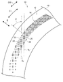
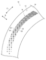
- a tire side portion 12 which is an example of the outer surface of the tire 10, is provided with a decorative portion 14 extending in the tire circumferential direction (arrow C direction).
- the decorative portion 14 has an arc shape when viewed from the axial direction of the tire 10, and is arranged at an arbitrary position in the tire circumferential direction.
- the tire side portion 12 other than the decorative portion 14 has a smooth surface like a normal tire.
- the portion of the tire side portion 12 that is formed as a smooth surface is appropriately referred to as a base surface 16 .
- the decorative portion 14 includes a plurality of first pattern regions 20 and second pattern regions 22 having different sizes and orientations.
- the first pattern area 20 and the second pattern area 22 are defined by the base surface (smooth surface) 16 over substantially the entire decorative portion 14 .
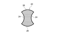
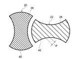
- the first pattern region 20 and the second pattern region 22 have the same outline shape in a plan view, but differ only in orientation, so the shape of the first pattern region 20 will be described as a representative.
- the first pattern region 20 includes a pair of arc recesses (inwardly protruding) 24 that face each other and a pair of arc protrusions (outwardly protruding) that are formed on both sides of the pair of arc recesses 24 and face each other. It has a shape configured with a convex) 26 .
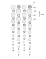
- the first pattern regions 20 and the second pattern regions 22 of the same size are alternately spaced apart on one line TL with respect to the tire circumferential direction, with their orientations changed by 90°. are placed.
- the line TL is inclined at an angle ⁇ with respect to the tire radial direction (arrow R direction).
- the size of the first pattern region 20 and the second pattern region 22 increases as they are arranged on the clockwise direction side (arrow CW direction side) as one side in the tire circumferential direction.
- the first pattern is arranged on another line TL′ arranged on the clockwise side compared to the first pattern region 20 and the second pattern region 22 arranged on the line TL.
- Region 20 and second pattern region 22 are large in size.
- the first pattern region 20 and the second pattern region 22 are exceptionally separated from each other without the base surface (smooth surface) 16 interposed therebetween. in contact with
- the first pattern area 20 has a lower lightness (L*) than the base surface 16 and appears blacker than the base surface 16 .
- the second pattern area 22 has a higher brightness than the first pattern area 20 and a lower brightness than the base surface 16 . That is, the brightness decreases in the order of the base surface 16, the second pattern region 22, and the first pattern region 20. Compared to the base surface 16, the second pattern region 22 appears black, and the first pattern region 20 appears black. It looks blacker than the second pattern region 22, and the first pattern region 20 looks the blackest.
- the surface of the tire side portion 12 is formed to have the first shape.
- a patterned area 20 and a second patterned area 22 may be formed.
- first pattern region 20 and the second pattern region 22 minute projections are formed that protrude from the base surface 16, so that the surfaces of the first pattern region 20 and the second pattern region 22 are uneven.
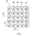
- first asterisk projections 34 and second asterisk projections 36 which are examples of projections, are formed in the first pattern region 20 and the second pattern region 22 to be similar to each other.
- the shapes of the first asterisk projection 34 and the second asterisk projection 36 are similar in their respective regions.
- the distance P between the first asterisk projection 34 and the second asterisk projection 36 adjacent to each other changes according to the similitude ratio.
- the shapes of the first asterisk projection 34 and the second asterisk projection 36 are similar in their respective regions. Accordingly, the shapes of the first asterisk projection 34 and the second asterisk projection 36 will be described below using the first pattern region 20 as an example.
- the first pattern area 20 has a plurality of first asterisk protrusions 34 and a plurality of second asterisk protrusions 36 projecting from the base surface 16 .
- the first asterisk projections 34 and the second asterisk projections 36 are alternately arranged in the tire circumferential direction and the tire radial direction.
- first asterisk projection 34 As shown in FIG. 3A, the first asterisk projections 34 are a plurality of projections extending in different directions from the center O1 as a base point when viewed from the direction perpendicular to the base surface 16 (rotational axis direction of the tire 10). , six extensions 34E are provided in this embodiment.
- the six extending portions 34E form an angle of 60° with each adjacent extending portion 34E.
- the first asterisk projection 34 has a shape in which six extending portions 34E extend radially from the center O1.
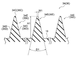
- the cross section in the direction orthogonal to the extending direction has a substantially isosceles triangle shape with a flat top surface 34C. That is, the first asterisk projection 34 has a top surface 34C and a pair of side surfaces 34D.
- the width of the top surface 34C (W1 in the drawing) is 0.02 mm
- the vertical angle of the first asterisk projection 34 (D1 in the drawing) is 26 degrees.
- the height (H in the drawing) of the first asterisk projection 34 is a predetermined value of 0.05 mm or more and 1.0 mm or less.
- the height of the protrusion is less than 0.05 [mm]
- it becomes difficult to form the protrusion and there is a possibility that the incident light may be attenuated and the brightness may not be lowered to the extent that it appears black. be.
- the height of the projection is set to 1.0 mm or less, the difference between the rigidity of the projection portion and the rigidity of the surrounding portion of the projection is reduced, thereby suppressing local stress concentration. ing.
- the height of the protrusions in the present embodiment and the dimensions such as the spacing (pitch) of the protrusions described later can be measured using, as an example, a one-shot 3D shape measuring machine VR-3000 series manufactured by Keyence Corporation. .
- the second asterisk projection 36 has a similar shape to the first asterisk projection 34 .
- the second asterisk projection 36 rotates the first asterisk projection 34 clockwise 90 degrees about the center O1 when viewed from a direction orthogonal to the base surface 16, and further, It has a shape in which the first asterisk projection 34 rotated 90 degrees around the center O1 is turned upside down. That is, the second asterisk projection 36 has six extending portions 36E extending in different directions from the center O2 as a base point, and each extending portion 36E has a top surface 36C and side surfaces 36D. ing.
- the first asterisk projections 34 and the second asterisk projections 36 are alternately arranged in the tire circumferential direction and the tire radial direction, filling the entire area.
- the distance between the center O1 and the center O2 (hereinafter referred to as the "distance P") is 0.1. It is set to a predetermined value equal to or greater than [mm] and equal to or less than 1.0 [mm]. If the interval P is less than 0.1 [mm], it will be difficult to form the protrusions. Furthermore, if the interval P is larger than 1.0 [mm], there is a possibility that the incident light cannot be attenuated and the lightness cannot be lowered to the extent that it looks black.
- first asterisk projections 34 and second asterisk projections 36 similar in shape to the first pattern region 20 are formed. , is lower than the density of the protrusions formed in the first pattern region 20 . As a result, the second pattern area 22 appears brighter than the first pattern area 20 .
- the first pattern regions 20 and the second pattern regions 22 are preferably arranged in three or more, more preferably five or more, in the tire circumferential direction.
- the incident light is reflected outward by the smooth outer surface that constitutes the base surface 16 .
- the first pattern area 20 and the second pattern area 22 the light incident on the first asterisk projection 34 and the second asterisk projection 36 hits the side surfaces 34D and 36D shown in FIG. The incident light is attenuated while being repeatedly reflected between the facing side surfaces 34D and 36D, and is reflected outward. Therefore, the first pattern area 20 and the second pattern area 22 appear black compared to the base surface 16 .
- the area occupied by the base surface 16 of the second pattern area 22 per unit area is smaller than the area occupied by the base surface 16 of the first pattern area 20 per unit area. and widen.
- the amount of light reflected outward from the second pattern area 22 is greater than the amount of light reflected outward from the first pattern area 20 . That is, the brightness of the second pattern area 22 is higher than that of the first pattern area 20 . In other words, the second patterned area 22 appears relatively lighter than the first patterned area 20 , and the first patterned area 20 appears relatively darker than the second patterned area 22 .
- the decorative portion 14 of the present embodiment includes a plurality of first pattern regions 20 and a plurality of second patterns arranged adjacent to the first pattern region 20 and having higher brightness than the first pattern region 20. 22 are provided, and the areas of the first pattern region 20 and the second pattern region 22 increase in the clockwise direction. For this reason, the decorative portion 14 of the present embodiment can greatly expand the range of expression compared to a decorative portion that is not configured in this way. can guide the eye.
- symbol is attached
- the first pattern region 20 and the second pattern region 22 provided on the tire side portion 12 of the tire 10 of the present embodiment have contour shapes similar to those of the first embodiment. Although the pattern area 20 and the second pattern area 22 are similar, the shape of the protrusions is different.
- a plurality of linearly extending rib-like projections 38 are provided in the first pattern region 20 and the second pattern region 22 of the present embodiment, as an example of projections.
- the rib-shaped projections 38 can also be called ridges (mountain ridge-shaped projections; see FIG. 4). It should be noted that the outline portion of the outer circumference of each region in this embodiment is formed of rib-like projections 40 similar to the rib-like projections 38 .
- the height of the rib-shaped projections 38 is 0.15 mm as an example, and the apex angle is 35 [degrees] as an example.
- the rib-like projection 40 has a height of 0.3 mm, for example, and an apex angle of 35 degrees, for example. These heights and apex angles can be changed as appropriate.
- the rib-shaped projections 38 are arranged in parallel along one direction, and the distance P between the center of one rib-shaped projection 38 and the center of the other adjacent rib-shaped projection 38 is shown in FIGS. 3A and 3B. Similar to the spacing between the first asterisk projection 34 and the second asterisk projection 36 .
- the interval P between the rib-shaped projections 38 in the second pattern region 22 is wider than the interval P between the rib-shaped projections 38 in the first pattern region 20, and the second pattern region 22 is closer to the first pattern. It appears relatively brighter than the region 20 .
- the decorative portion 14 including the first pattern region 20 and the second pattern region 22 of the present embodiment can also obtain the same functions and effects as the decorative portion 14 of the first embodiment.
- the first asterisk projection 34 and the second asterisk projection 36 are connected to each other, but they may be configured so that they are not connected to each other.
- the apex angle of the projections such as the first asterisk projection 34 and the second asterisk projection 36 was set to 26 [degrees], but other angles may be used. As the apex angle D1 increases, the proportion of the reflected light reflected by the side surfaces 34D and 36D returning to the direction of incidence increases, and the brightness increases relatively.
- the first asterisk projection 34 and the second asterisk projection 36 having a plurality of radially extending extensions 34E, and the linearly extending rib-like projection 38 were given as examples of projections.
- the disclosure is not limited to this, and the planar shape of the protrusions is not limited to radial or linear, and may be a so-called embossed pattern.
- Grain patterns are patterns including, for example, leather patterns, satin patterns, wood grain patterns, texture patterns, and geometric patterns.
- first pattern region 20 and the second pattern region 22 are not limited to having the same shape as shown in the above embodiment, and may have different shapes, and the shape of each region is arbitrary.
- first pattern area 20 may be circular and the second pattern area 22 may be square.
- one side in the tire circumferential direction is the clockwise direction side (arrow CW direction side), but the one side in the tire circumferential direction may be the counterclockwise direction side.
- the decorative portion 14 of the above embodiment has two pattern areas with different brightness, it may have three or more pattern areas with different brightness.
Landscapes
- Engineering & Computer Science (AREA)
- Mechanical Engineering (AREA)
- Tires In General (AREA)
Abstract
This tire comprises a first pattern region that is formed by recesses and protrusions, and a second pattern region that has a higher brightness than that of the first pattern region, both of which are disposed on a tire side portion, wherein a plurality of the first pattern regions and the second pattern regions are disposed in the tire circumferential direction, the area of the first pattern regions and the area of the second pattern regions increase toward the clockwise direction side of the tire circumferential direction.
Description
本開示は、タイヤに関する。
This disclosure relates to tires.
タイヤの側面の平滑面に微小の凹凸を形成した装飾を設けることが行われている(例えば、特開2019-099094号公報参照)。
The smooth surface of the side surface of the tire is decorated with minute unevenness (for example, see Japanese Patent Application Laid-Open No. 2019-099094).
本開示は、装飾部分の表現の幅を広げることができるタイヤの提供を目的とする。
An object of the present disclosure is to provide a tire that can expand the range of expression of decorative parts.
第1の態様に係るは、タイヤ外面に配置され、各々が凹凸によって形成される第1パターン領域と、前記第1パターン領域よりも明度が高い第2パターン領域とを備え、前記第1パターン領域、及び前記第2パターン領域がタイヤ周方向に複数配置され、前記第1パターン領域の面積、及び前記第2パターン領域の面積は、タイヤ周方向一方側に向かって増加している。
According to a first aspect, a first pattern region arranged on the outer surface of the tire and each formed by unevenness and a second pattern region having a higher brightness than the first pattern region, the first pattern region , and a plurality of the second pattern regions are arranged in the tire circumferential direction, and the area of the first pattern region and the area of the second pattern region increase toward one side in the tire circumferential direction.
第1の態様に係るタイヤでは、各々が凹凸によって形成され、第1パターン領域と、第1パターン領域と隣接して配置され第1パターン領域よりも明度が高い第2のパターンがタイヤ外面に配置されており、第1パターン領域、及び第2パターン領域がタイヤ周方向に複数配置され、第1パターン領域の面積、及び第2パターン領域の面積が、タイヤ周方向一方側に向かって増加している。
このため、このようにタイヤの外面が装飾されていない場合に比較して、装飾部分の表現の幅を広げることができる。 In the tire according to the first aspect, the first pattern area and the second pattern, which are arranged adjacent to the first pattern area and have a higher brightness than the first pattern area, are arranged on the outer surface of the tire. A plurality of first pattern regions and second pattern regions are arranged in the tire circumferential direction, and the area of the first pattern region and the area of the second pattern region increase toward one side in the tire circumferential direction. there is
Therefore, compared to the case where the outer surface of the tire is not decorated in this way, the expression of the decorative portion can be expanded.
第2の態様に係るタイヤは、第1の態様に係るタイヤにおいて、複数の前記第1パターン領域、及び複数の前記第2パターン領域の少なくとも一部は、平滑面で区画されている。
A tire according to a second aspect is the tire according to the first aspect, wherein at least a portion of the plurality of first pattern regions and the plurality of second pattern regions are partitioned by a smooth surface.
複数の第1パターン領域、及び複数の第2パターン領域のうちの少なくとも一部を、平滑面で区画することで、複数の第1パターン領域、及び複数の第2パターン領域のうちの少なくとも一部を、平滑面で区画しない場合に比較して、装飾部分の表現の幅を更に広げることができる。
At least some of the plurality of first pattern regions and the plurality of second pattern regions are partitioned by a smooth surface, so that at least some of the plurality of first pattern regions and the plurality of second pattern regions can further expand the range of expression of the decorative portion compared to the case where the is not partitioned by the smooth surface.
第3の態様に係るタイヤは、第1の態様または第2の態様に係るタイヤにおいて、複数の前記第1パターン領域、及び複数の前記第2パターン領域の少なくとも一方は、同一形状とされ、かつタイヤ周方向の一方側に向かうにしたがって面積が増加している。
A tire according to a third aspect is the tire according to the first aspect or the second aspect, wherein at least one of the plurality of first pattern regions and the plurality of second pattern regions has the same shape, and The area increases toward one side in the tire circumferential direction.
複数の第1パターン領域、及び複数の第2パターン領域の少なくとも一方を、同一形状とし、かつタイヤ周方向の一方側に向かうにしたがって面積を増加させることで、複数の第1パターン領域、及び複数の第2パターン領域の少なくとも一方を、同一形状とせず、かつタイヤ周方向の一方側に向かうにしたがって面積を増加させない場合に比較して、装飾部分の表現の幅を更に広げることができる。
また、複数の第1パターン領域、及び複数の第2パターン領域の少なくとも一方を、同一形状とし、かつタイヤ周方向の一方側に向かうにしたがって面積を増加させることで、装飾部分を見たときに、タイヤ周方向の一方側に向けて視線を誘導することができる。 At least one of the plurality of first pattern regions and the plurality of second pattern regions has the same shape, and by increasing the area toward one side in the tire circumferential direction, the plurality of first pattern regions and the plurality of At least one of the second pattern regions does not have the same shape and does not increase in area toward one side in the tire circumferential direction, the range of expression of the decorative portion can be further expanded.
In addition, at least one of the plurality of first pattern regions and the plurality of second pattern regions has the same shape, and the area is increased toward one side in the tire circumferential direction, so that when the decorative portion is viewed, , the line of sight can be guided toward one side in the tire circumferential direction.
以上説明したように本開示のタイヤによれば、タイヤ外面の装飾部分の表現の幅を広げることができる、という優れた効果を有する。
As described above, according to the tire of the present disclosure, there is an excellent effect that it is possible to expand the range of expression of the decorative portion of the tire outer surface.
[第1の実施形態]
図1~図4を用いて、本開示の第1の実施形態に係るタイヤ10について説明する。なお、図中に示す矢印Cは、タイヤ周方向を示し、矢印CW方向は、時計回り方向を示し、矢印CCW方向は、反時計回り方向を示し、矢印Rは、タイヤ径方向を示す。 [First Embodiment]
Atire 10 according to a first embodiment of the present disclosure will be described with reference to FIGS. 1 to 4. FIG. Arrow C shown in the drawing indicates the tire circumferential direction, arrow CW indicates the clockwise direction, arrow CCW indicates the counterclockwise direction, and arrow R indicates the tire radial direction.
図1~図4を用いて、本開示の第1の実施形態に係るタイヤ10について説明する。なお、図中に示す矢印Cは、タイヤ周方向を示し、矢印CW方向は、時計回り方向を示し、矢印CCW方向は、反時計回り方向を示し、矢印Rは、タイヤ径方向を示す。 [First Embodiment]
A
図1に示されるように、タイヤ10の外面の一例たるタイヤサイド部12には、タイヤ周方向(矢印C方向)に延びる装飾部14が設けられている。装飾部14は、タイヤ10の軸方向から見て円弧状とされ、タイヤ周方向の任意の位置に配置されている。
As shown in FIG. 1, a tire side portion 12, which is an example of the outer surface of the tire 10, is provided with a decorative portion 14 extending in the tire circumferential direction (arrow C direction). The decorative portion 14 has an arc shape when viewed from the axial direction of the tire 10, and is arranged at an arbitrary position in the tire circumferential direction.
装飾部14以外のタイヤサイド部12は、通常のタイヤと同様に平滑面とされている。なお、タイヤサイド部12における平滑面とされた部分は、適宜ベース面16と呼ぶ。
The tire side portion 12 other than the decorative portion 14 has a smooth surface like a normal tire. In addition, the portion of the tire side portion 12 that is formed as a smooth surface is appropriately referred to as a base surface 16 .
装飾部14は、大きさ、及び向きの異なる複数の第1パターン領域20と第2パターン領域22とを含んで構成されている。第1パターン領域20、及び第2パターン領域22は、装飾部14の略全体に渡ってベース面(平滑面)16によって区画されている。
The decorative portion 14 includes a plurality of first pattern regions 20 and second pattern regions 22 having different sizes and orientations. The first pattern area 20 and the second pattern area 22 are defined by the base surface (smooth surface) 16 over substantially the entire decorative portion 14 .
なお、第1パターン領域20と第2パターン領域22とは、平面視で同一の輪郭形状であり、向きが異なるだけであるので、代表して第1パターン領域20の形状を説明する。
図2に示すように、第1パターン領域20は、互いに対向する一対の円弧凹部(内側へ凸)24と、一対の円弧凹部24の両側に形成され、互いに対向する一対の円弧凸部(外側へ凸)26とを有して構成された形状を呈している。 Note that thefirst pattern region 20 and the second pattern region 22 have the same outline shape in a plan view, but differ only in orientation, so the shape of the first pattern region 20 will be described as a representative.
As shown in FIG. 2, thefirst pattern region 20 includes a pair of arc recesses (inwardly protruding) 24 that face each other and a pair of arc protrusions (outwardly protruding) that are formed on both sides of the pair of arc recesses 24 and face each other. It has a shape configured with a convex) 26 .
図2に示すように、第1パターン領域20は、互いに対向する一対の円弧凹部(内側へ凸)24と、一対の円弧凹部24の両側に形成され、互いに対向する一対の円弧凸部(外側へ凸)26とを有して構成された形状を呈している。 Note that the
As shown in FIG. 2, the
図1に示すように、同一サイズの第1パターン領域20と第2パターン領域22とが、互いにその向きを90°変えて、タイヤ周方向に対する一つの線TL上に、間隔を開けて交互に配置されている。なお、線TLは、タイヤ径方向(矢印R方向)に対して、角度θで傾斜している。
As shown in FIG. 1, the first pattern regions 20 and the second pattern regions 22 of the same size are alternately spaced apart on one line TL with respect to the tire circumferential direction, with their orientations changed by 90°. are placed. Note that the line TL is inclined at an angle θ with respect to the tire radial direction (arrow R direction).
さらに、第1パターン領域20、及び第2パターン領域22は、タイヤ周方向の一方側としての時計回り方向側(矢印CW方向側)に配置されるものほど、サイズが大きくなっている。本実施形態では、線TL上に配置される第1パターン領域20、及び第2パターン領域22に比較して、時計回り方向側に配置される他の線TL’上に配置される第1パターン領域20、及び第2パターン領域22は、サイズが大きい。
Furthermore, the size of the first pattern region 20 and the second pattern region 22 increases as they are arranged on the clockwise direction side (arrow CW direction side) as one side in the tire circumferential direction. In the present embodiment, the first pattern is arranged on another line TL′ arranged on the clockwise side compared to the first pattern region 20 and the second pattern region 22 arranged on the line TL. Region 20 and second pattern region 22 are large in size.
なお、本実施形態では、装飾部14の時計回り方向側においては、例外的に、一部の第1パターン領域20と第2パターン領域22とがベース面(平滑面)16を介さずに互いに接している。
In the present embodiment, on the clockwise direction side of the decorative portion 14, the first pattern region 20 and the second pattern region 22 are exceptionally separated from each other without the base surface (smooth surface) 16 interposed therebetween. in contact with
第1パターン領域20は、ベース面16に比較して明度(L*)が低く、ベース面16に比較して黒色に見える。第2パターン領域22は、第1パターン領域20よりは明度が高く、かつベース面16よりは明度が低い。即ち、ベース面16、第2パターン領域22、第1パターン領域20の順で明度が低くなっており、ベース面16に比較して第2パターン領域22は黒く見え、第1パターン領域20は第2パターン領域22に比較して黒く見え、第1パターン領域20が最も黒く見える。
The first pattern area 20 has a lower lightness (L*) than the base surface 16 and appears blacker than the base surface 16 . The second pattern area 22 has a higher brightness than the first pattern area 20 and a lower brightness than the base surface 16 . That is, the brightness decreases in the order of the base surface 16, the second pattern region 22, and the first pattern region 20. Compared to the base surface 16, the second pattern region 22 appears black, and the first pattern region 20 appears black. It looks blacker than the second pattern region 22, and the first pattern region 20 looks the blackest.
なお、タイヤ10を成形するためのモールド(金型)において、第1パターン領域20、及び第2パターン領域22に対応する部分に微小な凹凸を設けることによって、タイヤサイド部12の表面に第1パターン領域20、及び第2パターン領域22を形成することができる。
In addition, in the mold (mold) for molding the tire 10 , by providing minute irregularities in portions corresponding to the first pattern region 20 and the second pattern region 22 , the surface of the tire side portion 12 is formed to have the first shape. A patterned area 20 and a second patterned area 22 may be formed.
第1パターン領域20、及び第2パターン領域22には、ベース面16から突出する微小な突起が形成され、これにより第1パターン領域20、及び第2パターン領域22の各々の表面が凹凸している。
In the first pattern region 20 and the second pattern region 22, minute projections are formed that protrude from the base surface 16, so that the surfaces of the first pattern region 20 and the second pattern region 22 are uneven. there is
図3A、図3Bに示すように、第1パターン領域20、及び第2パターン領域22には、突起の一例としての第一アスタリスク突起34及び第二アスタリスク突起36が、互いに相似に形成されている。
第一アスタリスク突起34及び第二アスタリスク突起36の形状は、各々の領域において相似である。また、互いに隣接する第一アスタリスク突起34と第二アスタリスク突起36との間隔Pは、相似比に応じて変化している。 As shown in FIGS. 3A and 3B,first asterisk projections 34 and second asterisk projections 36, which are examples of projections, are formed in the first pattern region 20 and the second pattern region 22 to be similar to each other. .
The shapes of thefirst asterisk projection 34 and the second asterisk projection 36 are similar in their respective regions. Also, the distance P between the first asterisk projection 34 and the second asterisk projection 36 adjacent to each other changes according to the similitude ratio.
第一アスタリスク突起34及び第二アスタリスク突起36の形状は、各々の領域において相似である。また、互いに隣接する第一アスタリスク突起34と第二アスタリスク突起36との間隔Pは、相似比に応じて変化している。 As shown in FIGS. 3A and 3B,
The shapes of the
上記したように、第一アスタリスク突起34及び第二アスタリスク突起36の形状は、各々の領域において相似である。したがって、第一アスタリスク突起34及び第二アスタリスク突起36の形状については、第1パターン領域20を例に挙げて以下に説明する。
As described above, the shapes of the first asterisk projection 34 and the second asterisk projection 36 are similar in their respective regions. Accordingly, the shapes of the first asterisk projection 34 and the second asterisk projection 36 will be described below using the first pattern region 20 as an example.
(第1パターン領域20)
図3Aに示すように、第1パターン領域20は、ベース面16から突出した複数の第一アスタリスク突起34と、複数の第二アスタリスク突起36とを有している。そして、第一アスタリスク突起34と、第二アスタリスク突起36とは、タイヤ周方向、及びタイヤ径方向に交互に配置されている。 (First pattern area 20)
As shown in FIG. 3A, thefirst pattern area 20 has a plurality of first asterisk protrusions 34 and a plurality of second asterisk protrusions 36 projecting from the base surface 16 . The first asterisk projections 34 and the second asterisk projections 36 are alternately arranged in the tire circumferential direction and the tire radial direction.
図3Aに示すように、第1パターン領域20は、ベース面16から突出した複数の第一アスタリスク突起34と、複数の第二アスタリスク突起36とを有している。そして、第一アスタリスク突起34と、第二アスタリスク突起36とは、タイヤ周方向、及びタイヤ径方向に交互に配置されている。 (First pattern area 20)
As shown in FIG. 3A, the
(第一アスタリスク突起34)
図3Aに示すように、 第一アスタリスク突起34は、ベース面16に対して直交する方向(タイヤ10の回転軸方向)から見て、基点としての中心O1からそれぞれ異なる方向へ延出された複数、本実施形態では6本の延出部34Eを備えている。 (first asterisk projection 34)
As shown in FIG. 3A, the firstasterisk projections 34 are a plurality of projections extending in different directions from the center O1 as a base point when viewed from the direction perpendicular to the base surface 16 (rotational axis direction of the tire 10). , six extensions 34E are provided in this embodiment.
図3Aに示すように、 第一アスタリスク突起34は、ベース面16に対して直交する方向(タイヤ10の回転軸方向)から見て、基点としての中心O1からそれぞれ異なる方向へ延出された複数、本実施形態では6本の延出部34Eを備えている。 (first asterisk projection 34)
As shown in FIG. 3A, the first
6本の延出部34Eは、隣り合う延出部34Eと、それぞれ60°の角度を成している。第一アスタリスク突起34は、換言すると、中心O1から6本の延出部34Eが放射状に延出された形状となっている。
The six extending portions 34E form an angle of 60° with each adjacent extending portion 34E. In other words, the first asterisk projection 34 has a shape in which six extending portions 34E extend radially from the center O1.
図4に示すように、第一アスタリスク突起34の延出部34Eにおいて、延出方向と直交する方向の断面は、平坦な頂面34Cを有する略二等辺三角形状とされている。つまり、第一アスタリスク突起34は、頂面34Cと、一対の側面34Dとを有している。本実施形態では、頂面34Cの幅(図中W1)は、0.02〔mm〕とされ、第一アスタリスク突起34の頂角(図中D1)は、26〔度〕とされている。また、第一アスタリスク突起34の高さ(図中H)は、0.05〔mm〕以上、1.0〔mm〕以下の予め決められた一の値とされている。突起の高さ(突出高さ)が0.05〔mm〕未満の場合は、突起の成形が困難になり、かつ、入射された光を減衰させて黒色に見える程度まで明度を低くできない虞がある。さらに、突起の高さを1.0〔mm〕以下とすることで、突起の部分の剛性と突起の周辺の部分の剛性との差を小さくし、局部的な応力集中を抑制させるようになっている。
As shown in FIG. 4, in the extending portion 34E of the first asterisk projection 34, the cross section in the direction orthogonal to the extending direction has a substantially isosceles triangle shape with a flat top surface 34C. That is, the first asterisk projection 34 has a top surface 34C and a pair of side surfaces 34D. In this embodiment, the width of the top surface 34C (W1 in the drawing) is 0.02 mm, and the vertical angle of the first asterisk projection 34 (D1 in the drawing) is 26 degrees. The height (H in the drawing) of the first asterisk projection 34 is a predetermined value of 0.05 mm or more and 1.0 mm or less. If the height of the protrusion (protrusion height) is less than 0.05 [mm], it becomes difficult to form the protrusion, and there is a possibility that the incident light may be attenuated and the brightness may not be lowered to the extent that it appears black. be. Furthermore, by setting the height of the projection to 1.0 mm or less, the difference between the rigidity of the projection portion and the rigidity of the surrounding portion of the projection is reduced, thereby suppressing local stress concentration. ing.
なお、本実施形態における突起の高さ及び後述する突起の間隔(ピッチ)等の寸法については、一例として、株式会社キーエンスのワンショット3D形状測定機VR-3000シリーズを用いて測定することができる。
Note that the height of the protrusions in the present embodiment and the dimensions such as the spacing (pitch) of the protrusions described later can be measured using, as an example, a one-shot 3D shape measuring machine VR-3000 series manufactured by Keyence Corporation. .
(第二アスタリスク突起36)
図3Aに示すように、第二アスタリスク突起36は、第一アスタリスク突起34と同様の形状をしている。具体的には、第二アスタリスク突起36は、ベース面16に対して直交する方向から見て、中心O1を中心にして第一アスタリスク突起34を時計回り方向に90〔度〕回転させ、さらに、中心O1を中心に90〔度〕回転させた第一アスタリスク突起34の上下を反転させた形状である。即ち、第二アスタリスク突起36は、基点としての中心O2からそれぞれ異なる方向へ延出された6本の延出部36Eを備えており、延出部36Eは、頂面36C、及び側面36Dを備えている。 (Second asterisk projection 36)
As shown in FIG. 3A, thesecond asterisk projection 36 has a similar shape to the first asterisk projection 34 . Specifically, the second asterisk projection 36 rotates the first asterisk projection 34 clockwise 90 degrees about the center O1 when viewed from a direction orthogonal to the base surface 16, and further, It has a shape in which the first asterisk projection 34 rotated 90 degrees around the center O1 is turned upside down. That is, the second asterisk projection 36 has six extending portions 36E extending in different directions from the center O2 as a base point, and each extending portion 36E has a top surface 36C and side surfaces 36D. ing.
図3Aに示すように、第二アスタリスク突起36は、第一アスタリスク突起34と同様の形状をしている。具体的には、第二アスタリスク突起36は、ベース面16に対して直交する方向から見て、中心O1を中心にして第一アスタリスク突起34を時計回り方向に90〔度〕回転させ、さらに、中心O1を中心に90〔度〕回転させた第一アスタリスク突起34の上下を反転させた形状である。即ち、第二アスタリスク突起36は、基点としての中心O2からそれぞれ異なる方向へ延出された6本の延出部36Eを備えており、延出部36Eは、頂面36C、及び側面36Dを備えている。 (Second asterisk projection 36)
As shown in FIG. 3A, the
第一アスタリスク突起34と第二アスタリスク突起36とは、タイヤ周方向、及びタイヤ径方向に交互に配置されており、各領域全体を埋めている。
The first asterisk projections 34 and the second asterisk projections 36 are alternately arranged in the tire circumferential direction and the tire radial direction, filling the entire area.
また、タイヤ径方向及びタイヤ周方向で隣り合う第一アスタリスク突起34と第二アスタリスク突起36において、中心O1と中心O2との間隔(以下「間隔P」)は、0.1
〔mm〕以上1.0〔mm〕以下の予め決められた一の値とされている。間隔Pが0.1〔mm〕未満の場合は、突起の成形が困難となる。さらに、間隔Pが1.0〔mm〕より大きくなると、入射された光を減衰させて黒色に見える程度まで明度を低くできない虞がある。 In addition, in thefirst asterisk projection 34 and the second asterisk projection 36 adjacent in the tire radial direction and the tire circumferential direction, the distance between the center O1 and the center O2 (hereinafter referred to as the "distance P") is 0.1.
It is set to a predetermined value equal to or greater than [mm] and equal to or less than 1.0 [mm]. If the interval P is less than 0.1 [mm], it will be difficult to form the protrusions. Furthermore, if the interval P is larger than 1.0 [mm], there is a possibility that the incident light cannot be attenuated and the lightness cannot be lowered to the extent that it looks black.
〔mm〕以上1.0〔mm〕以下の予め決められた一の値とされている。間隔Pが0.1〔mm〕未満の場合は、突起の成形が困難となる。さらに、間隔Pが1.0〔mm〕より大きくなると、入射された光を減衰させて黒色に見える程度まで明度を低くできない虞がある。 In addition, in the
It is set to a predetermined value equal to or greater than [mm] and equal to or less than 1.0 [mm]. If the interval P is less than 0.1 [mm], it will be difficult to form the protrusions. Furthermore, if the interval P is larger than 1.0 [mm], there is a possibility that the incident light cannot be attenuated and the lightness cannot be lowered to the extent that it looks black.
(第2パターン領域22)
次に、第2パターン領域22について説明する。
図3Bに示すように、第2パターン領域22には、第1パターン領域20と相似形の第一アスタリスク突起34及び第二アスタリスク突起36が形成されているが、形成されている突起の密度は、第1パターン領域20に形成されている突起の密度と比して、低くされている。これにより、第2パターン領域22は、第1パターン領域20に比較して、相対的に明るく見える。 (Second pattern area 22)
Next, thesecond pattern area 22 will be described.
As shown in FIG. 3B, in thesecond pattern region 22, first asterisk projections 34 and second asterisk projections 36 similar in shape to the first pattern region 20 are formed. , is lower than the density of the protrusions formed in the first pattern region 20 . As a result, the second pattern area 22 appears brighter than the first pattern area 20 .
次に、第2パターン領域22について説明する。
図3Bに示すように、第2パターン領域22には、第1パターン領域20と相似形の第一アスタリスク突起34及び第二アスタリスク突起36が形成されているが、形成されている突起の密度は、第1パターン領域20に形成されている突起の密度と比して、低くされている。これにより、第2パターン領域22は、第1パターン領域20に比較して、相対的に明るく見える。 (Second pattern area 22)
Next, the
As shown in FIG. 3B, in the
なお、第1パターン領域20、及び第2パターン領域22は、好ましくはタイヤ周方向に3つ以上、更に好ましくは5つ以上配置することが好ましい。
The first pattern regions 20 and the second pattern regions 22 are preferably arranged in three or more, more preferably five or more, in the tire circumferential direction.
(作用、効果)
次に、本実施形態に係るタイヤの作用効果について説明する。 (action, effect)
Next, the effects of the tire according to this embodiment will be described.
次に、本実施形態に係るタイヤの作用効果について説明する。 (action, effect)
Next, the effects of the tire according to this embodiment will be described.
タイヤサイド部12の突起が形成されていない他の領域、即ちベース面16では、入射した光は、ベース面16を構成する平滑な外面によって外側に反射される。
これに対し、第1パターン領域20、及び第2パターン領域22では、第一アスタリスク突起34及び第二アスタリスク突起36へ入射する光が、図4に示す側面34D、36Dに当たる。そして、入射した光は、向かい合う側面34D、36D間で反射を繰り返しながら減衰して外側に反射される。したがって、第1パターン領域20、及び第2パターン領域22は、ベース面16に比較して黒く見える。 In other regions of thetire side portion 12 where no projections are formed, that is, the base surface 16 , the incident light is reflected outward by the smooth outer surface that constitutes the base surface 16 .
On the other hand, in thefirst pattern area 20 and the second pattern area 22, the light incident on the first asterisk projection 34 and the second asterisk projection 36 hits the side surfaces 34D and 36D shown in FIG. The incident light is attenuated while being repeatedly reflected between the facing side surfaces 34D and 36D, and is reflected outward. Therefore, the first pattern area 20 and the second pattern area 22 appear black compared to the base surface 16 .
これに対し、第1パターン領域20、及び第2パターン領域22では、第一アスタリスク突起34及び第二アスタリスク突起36へ入射する光が、図4に示す側面34D、36Dに当たる。そして、入射した光は、向かい合う側面34D、36D間で反射を繰り返しながら減衰して外側に反射される。したがって、第1パターン領域20、及び第2パターン領域22は、ベース面16に比較して黒く見える。 In other regions of the
On the other hand, in the
さらに、それぞれの突起の頂角が同様であるため、第2パターン領域22のベース面16が単位面積当たりに占める領域は、第1パターン領域20のベース面16が単位面積当たりに占める領域と比して広くなる。
Furthermore, since the apex angles of the respective protrusions are the same, the area occupied by the base surface 16 of the second pattern area 22 per unit area is smaller than the area occupied by the base surface 16 of the first pattern area 20 per unit area. and widen.
これにより、第2パターン領域22において外側に反射される光の量は、第1パターン領域20において外側に反射される光の量と比して多くなる。つまり、第2パターン領域22の明度は、第1パターン領域20よりも高くなる。言い換えれば、第2パターン領域22は第1パターン領域20よりも相対的に明るく見え、第1パターン領域20は第2パターン領域22よりも相対的に黒く見える。
As a result, the amount of light reflected outward from the second pattern area 22 is greater than the amount of light reflected outward from the first pattern area 20 . That is, the brightness of the second pattern area 22 is higher than that of the first pattern area 20 . In other words, the second patterned area 22 appears relatively lighter than the first patterned area 20 , and the first patterned area 20 appears relatively darker than the second patterned area 22 .
このように、本実施形態の装飾部14には、複数の第1パターン領域20と、第1パターン領域20と隣接して配置され第1パターン領域20よりも明度が高い複数の第2のパターン22が設けられており、第1パターン領域20、及び第2パターン領域22の面積が、時計回り方向に向かって増加している。このため、このように構成されていない装飾部に比較して、本実施形態の装飾部14は、表現の幅を大きく広げることができ、また、装飾部14を見たときに、時計回り方向に視線を誘導することができる。
As described above, the decorative portion 14 of the present embodiment includes a plurality of first pattern regions 20 and a plurality of second patterns arranged adjacent to the first pattern region 20 and having higher brightness than the first pattern region 20. 22 are provided, and the areas of the first pattern region 20 and the second pattern region 22 increase in the clockwise direction. For this reason, the decorative portion 14 of the present embodiment can greatly expand the range of expression compared to a decorative portion that is not configured in this way. can guide the eye.
[第2実施形態]
次に、本開示の第2の実施形態に係るタイヤ10について説明する。なお、第1の実施形態と同一構成には同一符号を付し、その説明は省略する。
図5、及び図6に示すように、本実施形態のタイヤ10のタイヤサイド部12に設けられた第1パターン領域20と第2パターン領域22は、輪郭形状が第1の実施形態の第1パターン領域20と第2パターン領域22と同様であるが、突起の形状が異なっている。 [Second embodiment]
Next, atire 10 according to a second embodiment of the present disclosure will be described. In addition, the same code|symbol is attached|subjected to the same structure as 1st Embodiment, and the description is abbreviate|omitted.
As shown in FIGS. 5 and 6, thefirst pattern region 20 and the second pattern region 22 provided on the tire side portion 12 of the tire 10 of the present embodiment have contour shapes similar to those of the first embodiment. Although the pattern area 20 and the second pattern area 22 are similar, the shape of the protrusions is different.
次に、本開示の第2の実施形態に係るタイヤ10について説明する。なお、第1の実施形態と同一構成には同一符号を付し、その説明は省略する。
図5、及び図6に示すように、本実施形態のタイヤ10のタイヤサイド部12に設けられた第1パターン領域20と第2パターン領域22は、輪郭形状が第1の実施形態の第1パターン領域20と第2パターン領域22と同様であるが、突起の形状が異なっている。 [Second embodiment]
Next, a
As shown in FIGS. 5 and 6, the
本実施形態の第1パターン領域20、及び第2パターン領域22には、突起の一例として、直線状に延びる複数のリブ状突起38が設けられている。リブ状突起38は、リッジ(山の尾根状の突起。図4参照。)と言い換えることもできる。なお、本実施形態の各領域の外周の輪郭部分は、リブ状突起38と同様のリブ状突起40で形成されている。
A plurality of linearly extending rib-like projections 38 are provided in the first pattern region 20 and the second pattern region 22 of the present embodiment, as an example of projections. The rib-shaped projections 38 can also be called ridges (mountain ridge-shaped projections; see FIG. 4). It should be noted that the outline portion of the outer circumference of each region in this embodiment is formed of rib-like projections 40 similar to the rib-like projections 38 .
また、リブ状突起38の高さは、一例として0.15mmであり、頂角は、一例として35〔度〕である。リブ状突起40の高さは、一例として0.3mmであり、頂角は、一例として35〔度〕である。これらの高さ、頂角は適宜変更可能である。
Further, the height of the rib-shaped projections 38 is 0.15 mm as an example, and the apex angle is 35 [degrees] as an example. The rib-like projection 40 has a height of 0.3 mm, for example, and an apex angle of 35 degrees, for example. These heights and apex angles can be changed as appropriate.
リブ状突起38は、一方向に沿って並列されており、一方のリブ状突起38との中心と、隣接する他方のリブ状突起38の中心との間隔Pは、図3A、図3Bに示す第一アスタリスク突起34と第二アスタリスク突起36との間隔と同様である。
The rib-shaped projections 38 are arranged in parallel along one direction, and the distance P between the center of one rib-shaped projection 38 and the center of the other adjacent rib-shaped projection 38 is shown in FIGS. 3A and 3B. Similar to the spacing between the first asterisk projection 34 and the second asterisk projection 36 .
本実施形態においても、第2パターン領域22のリブ状突起38の間隔Pは、第1パターン領域20のリブ状突起38の間隔Pよりも広くなっており、第2パターン領域22が第1パターン領域20よりも相対的に明るく見えるようになっている。
なお、本実施形態の第1パターン領域20、及び第2パターン領域22を備えた装飾部14も、第1の実施形態の装飾部14と同様の作用、効果が得られる。 Also in the present embodiment, the interval P between the rib-shapedprojections 38 in the second pattern region 22 is wider than the interval P between the rib-shaped projections 38 in the first pattern region 20, and the second pattern region 22 is closer to the first pattern. It appears relatively brighter than the region 20 .
Thedecorative portion 14 including the first pattern region 20 and the second pattern region 22 of the present embodiment can also obtain the same functions and effects as the decorative portion 14 of the first embodiment.
なお、本実施形態の第1パターン領域20、及び第2パターン領域22を備えた装飾部14も、第1の実施形態の装飾部14と同様の作用、効果が得られる。 Also in the present embodiment, the interval P between the rib-shaped
The
[その他の実施形態]
以上、本開示の一実施形態について説明したが、本開示は、上記に限定されるものでなく、上記以外にも、その主旨を逸脱しない範囲内において種々変形して実施可能であることは勿論である。 [Other embodiments]
An embodiment of the present disclosure has been described above, but the present disclosure is not limited to the above, and can of course be implemented in various modifications other than the above without departing from the scope of the present disclosure. is.
例えば、上記第1実施形態では、第一アスタリスク突起34と第二アスタリスク突起36とが互いに連結されていたが、互いに連結されない構成であってもよい。
For example, in the first embodiment, the first asterisk projection 34 and the second asterisk projection 36 are connected to each other, but they may be configured so that they are not connected to each other.
第一アスタリスク突起34や第二アスタリスク突起36等の突起の頂角(例えば図4のD1)は、26〔度〕とされたが、他の角度であってもよい。頂角D1が大きくなると、側面34D、36Dで反射する反射光が、入射した方向に戻る割合が多くなり、相対的に明度が高くなる。
The apex angle of the projections such as the first asterisk projection 34 and the second asterisk projection 36 (for example, D1 in FIG. 4) was set to 26 [degrees], but other angles may be used. As the apex angle D1 increases, the proportion of the reflected light reflected by the side surfaces 34D and 36D returning to the direction of incidence increases, and the brightness increases relatively.
上記実施形態では、突起の一例として、放射状に延びる複数本の延出部34Eを備えた第一アスタリスク突起34、及び第二アスタリスク突起36、直線状に延びるリブ状突起38を挙げたが、本開示はこれに限らず、突起の平面視形状は、放射状、直線状に限らず、所謂シボ模様であってもよい。シボ模様とは、例えば、皮革模様、梨地模様、木目模様、布目模様、及び幾何学模様を含む模様のことである。
In the above embodiment, the first asterisk projection 34 and the second asterisk projection 36 having a plurality of radially extending extensions 34E, and the linearly extending rib-like projection 38 were given as examples of projections. The disclosure is not limited to this, and the planar shape of the protrusions is not limited to radial or linear, and may be a so-called embossed pattern. Grain patterns are patterns including, for example, leather patterns, satin patterns, wood grain patterns, texture patterns, and geometric patterns.
また、第1パターン領域20、及び第2パターン領域22は、上記実施形態で示したように同一形状に限らず、形状が異なっていてもよく、各領域の形状は任意である。一例として、図7に示すように、第1パターン領域20を円形、及び第2パターン領域22を四角形としてもよい。
Also, the first pattern region 20 and the second pattern region 22 are not limited to having the same shape as shown in the above embodiment, and may have different shapes, and the shape of each region is arbitrary. As an example, as shown in FIG. 7, the first pattern area 20 may be circular and the second pattern area 22 may be square.
上記実施形態では、タイヤ周方向の一方側を時計回り方向側(矢印CW方向側)としたが、タイヤ周方向の一方側は、反時計回り方向側であってもよい。
In the above embodiment, one side in the tire circumferential direction is the clockwise direction side (arrow CW direction side), but the one side in the tire circumferential direction may be the counterclockwise direction side.
上記実施形態の装飾部14では、明度の異なる2つのパターン領域を備えていたが、明度の異なる3つ以上のパターン領域を備えていてもよい。
Although the decorative portion 14 of the above embodiment has two pattern areas with different brightness, it may have three or more pattern areas with different brightness.
2021年3月16日に出願された日本国特許出願2021-042927号の開示は、その全体が参照により本明細書に取り込まれる。
本明細書に記載されたすべての文献、特許出願、及び技術規格は、個々の文献、特許出願、及び技術規格が参照により取り込まれることが具体的かつ個々に記された場合と同程度に、本明細書中に参照により取り込まれる。 The disclosure of Japanese Patent Application No. 2021-042927 filed on March 16, 2021 is incorporated herein by reference in its entirety.
All publications, patent applications and technical standards mentioned herein are to the same extent as if each individual publication, patent application and technical standard were specifically and individually noted to be incorporated by reference. incorporated herein by reference.
Claims (3)
- タイヤ外面に配置され、各々が凹凸によって形成される第1パターン領域と、前記第1パターン領域よりも明度が高い第2パターン領域とを備え、
前記第1パターン領域、及び前記第2パターン領域がタイヤ周方向に複数配置され、
前記第1パターン領域の面積、及び前記第2パターン領域の面積は、タイヤ周方向一方側に向かって増加している、
タイヤ。 A first pattern region arranged on the outer surface of the tire and each formed by unevenness, and a second pattern region having a higher brightness than the first pattern region,
A plurality of the first pattern region and the second pattern region are arranged in the tire circumferential direction,
The area of the first pattern region and the area of the second pattern region increase toward one side in the tire circumferential direction,
tire. - 複数の前記第1パターン領域、及び複数の前記第2パターン領域のうちの少なくとも一部は、平滑面で区画されている、
請求項1に記載のタイヤ。 At least some of the plurality of first pattern regions and the plurality of second pattern regions are partitioned by a smooth surface,
A tire according to claim 1 . - 複数の前記第1パターン領域、及び複数の前記第2パターン領域の少なくとも一方は、同一形状とされ、かつタイヤ周方向の一方側に向かうにしたがって面積が増加している、
請求項1または請求項2に記載のタイヤ。 At least one of the plurality of first pattern regions and the plurality of second pattern regions has the same shape, and the area increases toward one side in the tire circumferential direction.
A tire according to claim 1 or claim 2.
Applications Claiming Priority (2)
| Application Number | Priority Date | Filing Date | Title |
|---|---|---|---|
| JP2021-042927 | 2021-03-16 | ||
| JP2021042927A JP2022142663A (en) | 2021-03-16 | 2021-03-16 | tire |
Publications (1)
| Publication Number | Publication Date |
|---|---|
| WO2022195961A1 true WO2022195961A1 (en) | 2022-09-22 |
Family
ID=83320045
Family Applications (1)
| Application Number | Title | Priority Date | Filing Date |
|---|---|---|---|
| PCT/JP2021/042851 WO2022195961A1 (en) | 2021-03-16 | 2021-11-22 | Tire |
Country Status (2)
| Country | Link |
|---|---|
| JP (1) | JP2022142663A (en) |
| WO (1) | WO2022195961A1 (en) |
Citations (5)
| Publication number | Priority date | Publication date | Assignee | Title |
|---|---|---|---|---|
| US20020174928A1 (en) * | 2001-05-25 | 2002-11-28 | Ratliff Billy Joe | Tire sidewall |
| WO2013069260A1 (en) * | 2011-11-08 | 2013-05-16 | 株式会社ブリヂストン | Tire |
| JP2015042537A (en) * | 2013-08-26 | 2015-03-05 | 横浜ゴム株式会社 | Pneumatic tire |
| WO2018059758A1 (en) * | 2016-09-27 | 2018-04-05 | Continental Reifen Deutschland Gmbh | Vehicle tires |
| JP2019104279A (en) * | 2017-12-08 | 2019-06-27 | 株式会社ブリヂストン | tire |
-
2021
- 2021-03-16 JP JP2021042927A patent/JP2022142663A/en active Pending
- 2021-11-22 WO PCT/JP2021/042851 patent/WO2022195961A1/en active Application Filing
Patent Citations (5)
| Publication number | Priority date | Publication date | Assignee | Title |
|---|---|---|---|---|
| US20020174928A1 (en) * | 2001-05-25 | 2002-11-28 | Ratliff Billy Joe | Tire sidewall |
| WO2013069260A1 (en) * | 2011-11-08 | 2013-05-16 | 株式会社ブリヂストン | Tire |
| JP2015042537A (en) * | 2013-08-26 | 2015-03-05 | 横浜ゴム株式会社 | Pneumatic tire |
| WO2018059758A1 (en) * | 2016-09-27 | 2018-04-05 | Continental Reifen Deutschland Gmbh | Vehicle tires |
| JP2019104279A (en) * | 2017-12-08 | 2019-06-27 | 株式会社ブリヂストン | tire |
Also Published As
| Publication number | Publication date |
|---|---|
| JP2022142663A (en) | 2022-09-30 |
Similar Documents
| Publication | Publication Date | Title |
|---|---|---|
| JP6930908B2 (en) | tire | |
| EP3409509B1 (en) | Tire | |
| US20210129597A1 (en) | Tire | |
| WO2017130986A1 (en) | Tire | |
| JP7087246B2 (en) | tire | |
| US20200369095A1 (en) | Tire | |
| JP2006224704A (en) | Pneumatic tire | |
| JP5747826B2 (en) | Pneumatic tire | |
| JP6948930B2 (en) | tire | |
| WO2022195961A1 (en) | Tire | |
| JP6441170B2 (en) | tire | |
| JP6436861B2 (en) | tire | |
| WO2022195960A1 (en) | Tire | |
| WO2022195962A1 (en) | Tire | |
| JP6495736B2 (en) | tire | |
| EP3666555B1 (en) | Tire | |
| JP6930907B2 (en) | tire | |
| US20240131874A1 (en) | Tire | |
| WO2019116937A1 (en) | Tire | |
| US11479061B2 (en) | Tire | |
| JP6694282B2 (en) | tire | |
| US11097574B2 (en) | Tyre | |
| US20200369092A1 (en) | Tire | |
| TW202406766A (en) | Tire and its structure for enhancing visual contrast of tire edge |
Legal Events
| Date | Code | Title | Description |
|---|---|---|---|
| 121 | Ep: the epo has been informed by wipo that ep was designated in this application |
Ref document number: 21931704 Country of ref document: EP Kind code of ref document: A1 |
|
| NENP | Non-entry into the national phase |
Ref country code: DE |
|
| 122 | Ep: pct application non-entry in european phase |
Ref document number: 21931704 Country of ref document: EP Kind code of ref document: A1 |