WO2022195922A1 - コイル構造 - Google Patents
コイル構造 Download PDFInfo
- Publication number
- WO2022195922A1 WO2022195922A1 PCT/JP2021/032204 JP2021032204W WO2022195922A1 WO 2022195922 A1 WO2022195922 A1 WO 2022195922A1 JP 2021032204 W JP2021032204 W JP 2021032204W WO 2022195922 A1 WO2022195922 A1 WO 2022195922A1
- Authority
- WO
- WIPO (PCT)
- Prior art keywords
- coil
- coil structure
- point
- distance
- diameter
- Prior art date
- Legal status (The legal status is an assumption and is not a legal conclusion. Google has not performed a legal analysis and makes no representation as to the accuracy of the status listed.)
- Ceased
Links
Images





Classifications
-
- A—HUMAN NECESSITIES
- A61—MEDICAL OR VETERINARY SCIENCE; HYGIENE
- A61N—ELECTROTHERAPY; MAGNETOTHERAPY; RADIATION THERAPY; ULTRASOUND THERAPY
- A61N2/00—Magnetotherapy
- A61N2/02—Magnetotherapy using magnetic fields produced by coils, including single turn loops or electromagnets
-
- H—ELECTRICITY
- H01—ELECTRIC ELEMENTS
- H01F—MAGNETS; INDUCTANCES; TRANSFORMERS; SELECTION OF MATERIALS FOR THEIR MAGNETIC PROPERTIES
- H01F5/00—Coils
-
- H—ELECTRICITY
- H01—ELECTRIC ELEMENTS
- H01F—MAGNETS; INDUCTANCES; TRANSFORMERS; SELECTION OF MATERIALS FOR THEIR MAGNETIC PROPERTIES
- H01F7/00—Magnets
- H01F7/06—Electromagnets; Actuators including electromagnets
- H01F7/20—Electromagnets; Actuators including electromagnets without armatures
-
- A—HUMAN NECESSITIES
- A61—MEDICAL OR VETERINARY SCIENCE; HYGIENE
- A61N—ELECTROTHERAPY; MAGNETOTHERAPY; RADIATION THERAPY; ULTRASOUND THERAPY
- A61N2/00—Magnetotherapy
- A61N2/004—Magnetotherapy specially adapted for a specific therapy
- A61N2/006—Magnetotherapy specially adapted for a specific therapy for magnetic stimulation of nerve tissue
-
- H—ELECTRICITY
- H01—ELECTRIC ELEMENTS
- H01F—MAGNETS; INDUCTANCES; TRANSFORMERS; SELECTION OF MATERIALS FOR THEIR MAGNETIC PROPERTIES
- H01F5/00—Coils
- H01F2005/006—Coils with conical spiral form
Definitions
- the present invention relates to a coil structure suitable for generating a magnetic field, such as inside the human head.
- Transcranial magnetic stimulation which generates a magnetic field in a specific part of the brain for the purpose of treating depression, has been proposed.
- FIG. 9 is an appearance and conceptual diagram of a TMS device in the prior art.
- a patient sits on the sofa of the TMS apparatus, applies headgear 91 to the patient's head, and emits a magnetic field from a coil built into the headgear, thereby generating a magnetic field in a specific part of the brain.
- a dotted line 92 in the figure conceptually indicates a magnetic field generated from the apparatus, reference numeral 93 indicates an operation panel, reference numeral 94 indicates a power driver, and reference numeral 95 indicates a cooling unit.
- a coil structure in which a conductive wire is wound and 40 to 100% of the total length is wound on one conical surface.
- the angle between the axis and the generatrix is A coil structure characterized by winding with a coil diameter between a generatrix of 48 to 60° and a peripheral edge of a spherical body.
- the magnetic field generated inside the conical shape increases with respect to the current flowing through the coil. Therefore, the current flowing through the coil can be made relatively small, so the device for cooling the coil can be simplified.
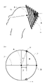
- FIG. 1 is a schematic illustration of the application of a coil according to the invention to the human head; FIG. It defines the radius a of the coil and the distance z to the point A to be acted upon.
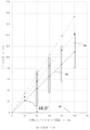
- Fig. 3 is a plot of the relationship between coil radius a and magnetic flux density B; The coil radius that gives the maximum value of the magnetic flux density shown in FIG. It is explanatory drawing of a cone.
- It is a layout diagram of a helical coil cross section.
- It is a layout diagram of a helical coil cross section.
- FIG. 4 is a schematic diagram of another example of a coil structure according to the present invention.
- FIG. 2 is a partial cross-sectional representation of a coil structure according to the present invention and is a plot of suitable winding diameters for a helical coil
- FIG. FIG. 2 is a partial cross-sectional representation of a coil structure according to the present invention and is a plot of suitable winding diameters for a helical coil
- FIG. FIG. 2 is a partial cross-sectional representation of a coil structure according to the present invention and is a plot of suitable winding diameters for a helical coil
- FIG. FIG. 2 is a partial cross-sectional representation of a coil structure according to the present invention and is a plot of suitable winding diameters for a helical coil
- FIG. FIG. 2 is a partial cross-sectional representation of a coil structure according to the present invention and is a plot of suitable winding diameters for a helical coil
- FIG. 1 is an appearance and conceptual diagram of a TMS device in the prior art
- FIG. 1 is an appearance and conceptual diagram of a TMS device
- the coil structure of the present invention is particularly useful when it is desired to generate a magnetic field in a place where conducting wires cannot be installed.
- a suitable example is when it is desired to generate a magnetic field inside the human head (inside the brain).
- Other non-limiting examples include application to places that are difficult to excise, such as the chest and abdominal organs of animals such as humans.
- FIG. 1 is a schematic diagram of the application of the coil according to the present invention to the human head.
- FIG. 1(A) is a schematic external view
- FIG. 1(B) simply shows a cross section passing through the central axis 15 of a one-turn circular coil
- 13 and 14 show cross sections of the coil itself. , indicating that current flows from 14 to the back of the paper and from 13 to the front of the paper.
- It is a diagram defining a distance z between a point A, which will be described later, and the center of the coil, and a radius a of the coil.
- the coil structure of the present invention consisting of conductors 11, is conical and in this configuration is attached to the human head 12. As shown in FIG.
- a point A in the figure is a location where a predetermined magnetic field is desired to be generated inside the head (inside the brain).
- Point B in the figure is the intersection of the surface 16 of the target spherical body and the central axis 15 of the coil, and is the extreme end of the head as the target.
- curve 16 in FIG. That is, no conductor can be installed inside the circle 16 .
- curve 16 can be considered to be the surface of a human head.
- Line 15 is the central axis of the cone formed by the coil structure.
- the point B mentioned above is located at the intersection of the central axis 15 and the curve 16 .
- Point A is a location where a predetermined magnetic field is desired to be generated as described above.
- Reference numerals 13 and 14 denote conducting wires that constitute the coil. In the drawing, r is the distance between the point A and the curve 16.
- FIG. When considering points 13 and 14 on the conductor, let a be the distance therefrom to central axis 15, and let Z be the distance from the point of projection of 13 onto central axis 15 to point A.
- FIG. 2 is a cross-sectional view including the central axis of the coil.
- I is the current value
- ⁇ 0 is the magnetic permeability of the vacuum
- ⁇ is the relative magnetic permeability of the air in FIG.
- FIG. 3 is a plot of the relationship between the radius of the coil and the magnetic flux density B when z, ie, the distance from the center of the coil to the point of action, is used as a parameter. According to this, it is easy to understand by looking at the plots when the positions are separated by 10 mm or 20 mm, for example, and it can be seen that there is an optimum value for the coil radius that can deliver the highest magnetic flux.
- the coil radius a that gives the maximum magnetic flux density at a certain point is It can be said that the arranged coils have the optimum shape.
- this shape is a conical shape with a small diameter near the target site and a larger diameter at a distance, so it may not be possible to place it inside the target site.
- the plot of ⁇ surrounded by an ellipse is close to the affected area, so the optimum coil diameter cannot be obtained, and the coil diameter is designed along the shape of the sphere.
- the plotted region surrounded by an ellipse indicates that the coil diameter can be designed with the optimum diameter.
- a coil is preferable, and in a coil that generates a magnetic field inside an object that cannot be placed inside, the distance (z′) from the axis of the coil to the surface of the object is equal to the distance (z ) is less than 1.4 times, and if greater, the radius is 1.4 times the distance z to the point of action.
- a specific shape of such a coil structure includes a coil structure in which a conductor wire is wound so as to form a single conical surface. is preferably 48° to 60°, and the optimum angle is 54.7°.
- FIG. 5 is an explanatory diagram of a cone, showing a generatrix 51, a central axis 52, and an angle ⁇ formed by them.
- the coil structure it is not necessary for all the conductors to be present on the conical surface for convenience of connection with the power supply, etc. Specifically, 40 to 100% of the total length of the conductors is on the above-mentioned one conical surface.
- FIG. 6-1 is a layout diagram of a helical coil cross-section, showing how the centers of the coil cross-sections 62 are arranged along the angle 54.7° between the generatrix 61 and the coil center axis 60.
- FIG. The actual cross-sectional shape of the coil is rectangular or circular like 62, and when wound as a coil, the coil has an inner diameter and an outer diameter. The angle between the innermost surfaces of the coil is smaller than 54.7°, and the angle between the outermost surfaces of the coil is larger than 54.7°.
- the current is concentrated on the inner and outer end faces of the coil due to the skin effect. sometimes appropriate.
- FIG. 6-2 shows an example in which the coil is wound so that the center of the cross section (reference numeral 64) of the terminal coil at the position of 100 mm coincides with the generatrix 63 forming an angle of 48° with the central axis 60.
- FIG. 6-3 shows an example in which the coil is wound so that the center of the cross section (reference numeral 66) of the terminal coil at the position of 100 mm coincides with the generatrix 65 forming an angle of 60° with the central axis 60. be.
- FIG. 7 is a schematic diagram of another example of the coil structure according to the present invention.
- This coil structure has a portion 71 in which a conductor wire is wound on a conical surface and a portion 72 in which a conductor wire is wound on a cylindrical surface. In the configuration of FIG. 7, approximately 50% of the total length of the wire occupies portion 71 .
- a core may be incorporated in the hollow portion of the coil at the portion 72 . Examples of materials for the core include iron, ferrite, amorphous metal materials, and the like.
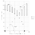
- FIG. 8-1 represents a portion of the cross section of the coil structure in the form of FIG. 7, and is a plot representing the appropriate winding diameter of the helical coil.
- Reference numeral 81 in this plot indicates that the conducting wire wound on the conical surface is wound with a coil diameter along the outer shape of the object to which the magnetic field is applied, such as the head. represents the area that can be taken by the coil radius of . From this plot, the following can be said. From the point of action, which is the origin (0, 0) of the graph in FIG.
- the coil diameter is defined by the region 82 surrounded by the parallel line of reference numeral 84 and the optimum line of reference numeral 83, and the core is placed inside. By arranging them, a stronger magnetic field can be generated.
- FIG. 8-1 shows the distance from the point of action up to 100 mm, the coil may be wound to a position farther than 100 mm, and the present invention is not limited to a distance of 100 mm.
- an appropriate coil design method is that, when the distance from the point of action 86 to the end of the object 87 is regarded as 100%, the distance from the point of action to 60% is the shape of the object. If the distance is 60% or more, the coil diameter may be determined between the optimum diameter 83 and the cylindrical winding 84 wound with the same diameter. As a first embodiment, if it is an air-core coil without a core, the coil is wound along 88 as shown in FIG. 8-2. As the second embodiment, a cylindrical shape along 88 as shown in FIG. 8-3 is the simplest configuration in terms of manufacturing. In addition, as a design method when the maximum depth of the action point is 80 mm from the edge 87 of the object, as shown in Fig.
- the coil is formed along the outer edge 891 of , and for 48 mm or more, the coil is formed with a constant radius like reference numeral 892, or the coil is formed along the optimum diameter like reference numerals 893 and 894. , 895, for example, a configuration in which the coil is wound with the same diameter after the end of the object.
- Each numerical value is one of examples, and depending on the size of the object, the depth of the point of action, and whether or not the core is built in, the horizontal axis of FIG. can be read as a percentage representing , and the coil radius can be designed so that the coil is positioned at the reference numeral 81 and the area 82 .
- the cross-sectional shape of the coil as indicated by reference numeral 896 is rectangular.
- coil is wound along the surface of the object, and in the region of 60% or more, the shape of the rectangular cross section is gradually changed as indicated by reference numeral 897, the inner diameter of the coil winding is kept constant, and the outer diameter of the coil winding is optimal You can also roll along the plot.
- the coil indicated by the coil code 897 may be formed by gradually changing the cross section of the wire material that is integrated in a spiral shape, and since the induced electromotive force can be used, the coil indicated by the code 897 is Each ring may be independent and may not be connected in series.
- FIG. 8-5 illustrates an example in which the coil cross sections are arranged at a pitch of 10 mm
- the pitch may be, for example, 5 mm, and is not limited to the illustrated dimensions.
Landscapes
- Health & Medical Sciences (AREA)
- Engineering & Computer Science (AREA)
- Electromagnetism (AREA)
- Physics & Mathematics (AREA)
- Public Health (AREA)
- Life Sciences & Earth Sciences (AREA)
- Animal Behavior & Ethology (AREA)
- General Health & Medical Sciences (AREA)
- Radiology & Medical Imaging (AREA)
- Veterinary Medicine (AREA)
- Nuclear Medicine, Radiotherapy & Molecular Imaging (AREA)
- Biomedical Technology (AREA)
- Power Engineering (AREA)
- Magnetic Treatment Devices (AREA)
- Particle Accelerators (AREA)
- Coils Or Transformers For Communication (AREA)
Priority Applications (4)
| Application Number | Priority Date | Filing Date | Title |
|---|---|---|---|
| CN202180095880.3A CN116997389A (zh) | 2021-03-18 | 2021-09-01 | 线圈构造 |
| EP21931666.8A EP4309727A4 (en) | 2021-03-18 | 2021-09-01 | COIL STRUCTURE |
| US18/550,953 US20240157165A1 (en) | 2021-03-18 | 2021-09-01 | Coil structure |
| JP2023506717A JP7758915B2 (ja) | 2021-03-18 | 2021-09-01 | コイル構造 |
Applications Claiming Priority (2)
| Application Number | Priority Date | Filing Date | Title |
|---|---|---|---|
| JP2021045298 | 2021-03-18 | ||
| JP2021-045298 | 2021-03-18 |
Publications (1)
| Publication Number | Publication Date |
|---|---|
| WO2022195922A1 true WO2022195922A1 (ja) | 2022-09-22 |
Family
ID=83319993
Family Applications (1)
| Application Number | Title | Priority Date | Filing Date |
|---|---|---|---|
| PCT/JP2021/032204 Ceased WO2022195922A1 (ja) | 2021-03-18 | 2021-09-01 | コイル構造 |
Country Status (5)
| Country | Link |
|---|---|
| US (1) | US20240157165A1 (https=) |
| EP (1) | EP4309727A4 (https=) |
| JP (1) | JP7758915B2 (https=) |
| CN (1) | CN116997389A (https=) |
| WO (1) | WO2022195922A1 (https=) |
Citations (5)
| Publication number | Priority date | Publication date | Assignee | Title |
|---|---|---|---|---|
| US5116304A (en) * | 1987-01-28 | 1992-05-26 | Cadwell Industries, Inc. | Magnetic stimulator with skullcap-shaped coil |
| JPH0852231A (ja) * | 1994-08-10 | 1996-02-27 | Akio Nagano | 磁気刺激装置 |
| CN109091758A (zh) * | 2018-07-18 | 2018-12-28 | 河南正治医疗器械有限公司 | 一种磁休克治疗仪的刺激线圈 |
| JP2020036993A (ja) * | 2014-01-15 | 2020-03-12 | ニューロネティクス インコーポレイテッド | 低減された表面刺激および改善された治療深さのための磁気刺激コイルおよび強磁性コンポーネント |
| JP2021045298A (ja) | 2019-09-18 | 2021-03-25 | グローブライド株式会社 | 衣服用ハンガー |
Family Cites Families (2)
| Publication number | Priority date | Publication date | Assignee | Title |
|---|---|---|---|---|
| GB9124379D0 (en) * | 1991-11-15 | 1992-01-08 | Magstim Company The Limited | Coils for magnetic nerve stimulators |
| US10037841B2 (en) | 2014-10-15 | 2018-07-31 | Vincent Suzara | Magnetic field structures, field generators, navigation and imaging for untethered robotic device enabled medical procedure |
-
2021
- 2021-09-01 WO PCT/JP2021/032204 patent/WO2022195922A1/ja not_active Ceased
- 2021-09-01 EP EP21931666.8A patent/EP4309727A4/en not_active Withdrawn
- 2021-09-01 JP JP2023506717A patent/JP7758915B2/ja active Active
- 2021-09-01 US US18/550,953 patent/US20240157165A1/en active Pending
- 2021-09-01 CN CN202180095880.3A patent/CN116997389A/zh active Pending
Patent Citations (5)
| Publication number | Priority date | Publication date | Assignee | Title |
|---|---|---|---|---|
| US5116304A (en) * | 1987-01-28 | 1992-05-26 | Cadwell Industries, Inc. | Magnetic stimulator with skullcap-shaped coil |
| JPH0852231A (ja) * | 1994-08-10 | 1996-02-27 | Akio Nagano | 磁気刺激装置 |
| JP2020036993A (ja) * | 2014-01-15 | 2020-03-12 | ニューロネティクス インコーポレイテッド | 低減された表面刺激および改善された治療深さのための磁気刺激コイルおよび強磁性コンポーネント |
| CN109091758A (zh) * | 2018-07-18 | 2018-12-28 | 河南正治医疗器械有限公司 | 一种磁休克治疗仪的刺激线圈 |
| JP2021045298A (ja) | 2019-09-18 | 2021-03-25 | グローブライド株式会社 | 衣服用ハンガー |
Non-Patent Citations (1)
| Title |
|---|
| See also references of EP4309727A4 |
Also Published As
| Publication number | Publication date |
|---|---|
| JP7758915B2 (ja) | 2025-10-23 |
| CN116997389A (zh) | 2023-11-03 |
| EP4309727A1 (en) | 2024-01-24 |
| EP4309727A4 (en) | 2024-11-13 |
| JPWO2022195922A1 (https=) | 2022-09-22 |
| US20240157165A1 (en) | 2024-05-16 |
Similar Documents
| Publication | Publication Date | Title |
|---|---|---|
| JP6190809B2 (ja) | 球状表面の構成部分の2つの層を有する磁気コイル | |
| US20140081069A1 (en) | Deep magnetic field generating apparatus | |
| CN111905267A (zh) | 用于经颅磁刺激的线材、经颅磁刺激线圈和经颅磁刺激仪 | |
| CA2443819A1 (en) | Apparatus and methods for delivery of transcranial magnetic stimulation | |
| JP2008177566A (ja) | 高q値、低体積空芯インダクタ | |
| US11541247B2 (en) | Magnetic stimulation probe | |
| JP2014527895A5 (https=) | ||
| US20250010089A1 (en) | Generating electromagnetic waves for transcranial magnetic stimulation | |
| US8062204B2 (en) | Coil device and magnetic field generating device | |
| JP2001046050A (ja) | 電磁放射線を用いて細胞を処置する装置と方法 | |
| WO2022195922A1 (ja) | コイル構造 | |
| KR101477085B1 (ko) | 초상자성 콜로이드를 이용한 유도발열장치 | |
| JP2016187364A (ja) | 磁束照射装置 | |
| CN112827067B (zh) | 一种经颅磁刺激线圈及经颅磁刺激装置 | |
| US20150273233A1 (en) | Device and Method for Deep Transcranial Magnetic Stimulation | |
| US8602960B2 (en) | K-Ring electromagnetic treatment apparatus, system and method for tumors, arthritis and other ailments | |
| CN118872007A (zh) | 向量势产生装置、向量势线圈配置方法、向量势变压器以及非接触馈电系统 | |
| CN109621208A (zh) | 一种用于经颅磁刺激的中空铁芯线圈 | |
| JP4966575B2 (ja) | 生体加温装置 | |
| AU2020308072B2 (en) | Hyperthermia implants and a method and system for heating the implant | |
| JP2016106888A (ja) | 励磁コイル及びコイルユニット | |
| JP4255466B2 (ja) | 生体内部加熱用磁束照射装置 | |
| EA032247B1 (ru) | Устройство и система для локальной магнитотерапии | |
| CN109696641B (zh) | 接收线圈装置及磁共振成像系统 | |
| JP2005058298A (ja) | 生体内局所加熱方法及び磁束照射装置 |
Legal Events
| Date | Code | Title | Description |
|---|---|---|---|
| 121 | Ep: the epo has been informed by wipo that ep was designated in this application |
Ref document number: 21931666 Country of ref document: EP Kind code of ref document: A1 |
|
| WWE | Wipo information: entry into national phase |
Ref document number: 2023506717 Country of ref document: JP |
|
| WWE | Wipo information: entry into national phase |
Ref document number: 18550953 Country of ref document: US |
|
| WWE | Wipo information: entry into national phase |
Ref document number: 202180095880.3 Country of ref document: CN |
|
| WWE | Wipo information: entry into national phase |
Ref document number: 2021931666 Country of ref document: EP |
|
| NENP | Non-entry into the national phase |
Ref country code: DE |
|
| ENP | Entry into the national phase |
Ref document number: 2021931666 Country of ref document: EP Effective date: 20231018 |
|
| WWW | Wipo information: withdrawn in national office |
Ref document number: 2021931666 Country of ref document: EP |