WO2022190864A1 - 電気接続箱 - Google Patents
電気接続箱 Download PDFInfo
- Publication number
- WO2022190864A1 WO2022190864A1 PCT/JP2022/007334 JP2022007334W WO2022190864A1 WO 2022190864 A1 WO2022190864 A1 WO 2022190864A1 JP 2022007334 W JP2022007334 W JP 2022007334W WO 2022190864 A1 WO2022190864 A1 WO 2022190864A1
- Authority
- WO
- WIPO (PCT)
- Prior art keywords
- hole
- heat absorbing
- absorbing member
- contact portion
- heat
- Prior art date
- Legal status (The legal status is an assumption and is not a legal conclusion. Google has not performed a legal analysis and makes no representation as to the accuracy of the status listed.)
- Ceased
Links
Images





Classifications
-
- B—PERFORMING OPERATIONS; TRANSPORTING
- B60—VEHICLES IN GENERAL
- B60R—VEHICLES, VEHICLE FITTINGS, OR VEHICLE PARTS, NOT OTHERWISE PROVIDED FOR
- B60R16/00—Electric or fluid circuits specially adapted for vehicles and not otherwise provided for; Arrangement of elements of electric or fluid circuits specially adapted for vehicles and not otherwise provided for
- B60R16/02—Electric or fluid circuits specially adapted for vehicles and not otherwise provided for; Arrangement of elements of electric or fluid circuits specially adapted for vehicles and not otherwise provided for electric constitutive elements
- B60R16/023—Electric or fluid circuits specially adapted for vehicles and not otherwise provided for; Arrangement of elements of electric or fluid circuits specially adapted for vehicles and not otherwise provided for electric constitutive elements for transmission of signals between vehicle parts or subsystems
- B60R16/0238—Electrical distribution centers
-
- B—PERFORMING OPERATIONS; TRANSPORTING
- B60—VEHICLES IN GENERAL
- B60R—VEHICLES, VEHICLE FITTINGS, OR VEHICLE PARTS, NOT OTHERWISE PROVIDED FOR
- B60R16/00—Electric or fluid circuits specially adapted for vehicles and not otherwise provided for; Arrangement of elements of electric or fluid circuits specially adapted for vehicles and not otherwise provided for
- B60R16/02—Electric or fluid circuits specially adapted for vehicles and not otherwise provided for; Arrangement of elements of electric or fluid circuits specially adapted for vehicles and not otherwise provided for electric constitutive elements
-
- H—ELECTRICITY
- H02—GENERATION; CONVERSION OR DISTRIBUTION OF ELECTRIC POWER
- H02G—INSTALLATION OF ELECTRIC CABLES OR LINES, OR OF COMBINED OPTICAL AND ELECTRIC CABLES OR LINES
- H02G3/00—Installations of electric cables or lines or protective tubing therefor in or on buildings, equivalent structures or vehicles
- H02G3/02—Details
- H02G3/08—Distribution boxes; Connection or junction boxes
- H02G3/16—Distribution boxes; Connection or junction boxes structurally associated with support for line-connecting terminals within the box
-
- H—ELECTRICITY
- H02—GENERATION; CONVERSION OR DISTRIBUTION OF ELECTRIC POWER
- H02G—INSTALLATION OF ELECTRIC CABLES OR LINES, OR OF COMBINED OPTICAL AND ELECTRIC CABLES OR LINES
- H02G5/00—Installations of bus-bars
- H02G5/06—Totally-enclosed installations, e.g. in metal casings
- H02G5/08—Connection boxes therefor
-
- H—ELECTRICITY
- H05—ELECTRIC TECHNIQUES NOT OTHERWISE PROVIDED FOR
- H05K—PRINTED CIRCUITS; CASINGS OR CONSTRUCTIONAL DETAILS OF ELECTRIC APPARATUS; MANUFACTURE OF ASSEMBLAGES OF ELECTRICAL COMPONENTS
- H05K7/00—Constructional details common to different types of electric apparatus
- H05K7/02—Arrangements of circuit components or wiring on supporting structure
- H05K7/026—Multiple connections subassemblies
-
- H—ELECTRICITY
- H05—ELECTRIC TECHNIQUES NOT OTHERWISE PROVIDED FOR
- H05K—PRINTED CIRCUITS; CASINGS OR CONSTRUCTIONAL DETAILS OF ELECTRIC APPARATUS; MANUFACTURE OF ASSEMBLAGES OF ELECTRICAL COMPONENTS
- H05K7/00—Constructional details common to different types of electric apparatus
- H05K7/14—Mounting supporting structure in casing or on frame or rack
- H05K7/1422—Printed circuit boards receptacles, e.g. stacked structures, electronic circuit modules or box like frames
- H05K7/1427—Housings
- H05K7/1432—Housings specially adapted for power drive units or power converters
- H05K7/14329—Housings specially adapted for power drive units or power converters specially adapted for the configuration of power bus bars
-
- H—ELECTRICITY
- H05—ELECTRIC TECHNIQUES NOT OTHERWISE PROVIDED FOR
- H05K—PRINTED CIRCUITS; CASINGS OR CONSTRUCTIONAL DETAILS OF ELECTRIC APPARATUS; MANUFACTURE OF ASSEMBLAGES OF ELECTRICAL COMPONENTS
- H05K7/00—Constructional details common to different types of electric apparatus
- H05K7/20—Modifications to facilitate cooling, ventilating, or heating
- H05K7/20845—Modifications to facilitate cooling, ventilating, or heating for automotive electronic casings
-
- H—ELECTRICITY
- H05—ELECTRIC TECHNIQUES NOT OTHERWISE PROVIDED FOR
- H05K—PRINTED CIRCUITS; CASINGS OR CONSTRUCTIONAL DETAILS OF ELECTRIC APPARATUS; MANUFACTURE OF ASSEMBLAGES OF ELECTRICAL COMPONENTS
- H05K7/00—Constructional details common to different types of electric apparatus
- H05K7/20—Modifications to facilitate cooling, ventilating, or heating
- H05K7/2089—Modifications to facilitate cooling, ventilating, or heating for power electronics, e.g. for inverters for controlling motor
- H05K7/209—Heat transfer by conduction from internal heat source to heat radiating structure
Definitions
- FIG. 1 is a perspective view showing an electrical junction box according to Embodiment 1;
- FIG. FIG. 2 is a perspective view showing a state in which an upper case is omitted in the electrical connection box according to Embodiment 1;
- FIG. 3 is a partial cross-sectional view taken along line III-III of FIG. 2; 4 is a cross-sectional view taken along line IV-IV of FIG. 3;
- FIG. 3 is a diagram showing the positional relationship between busbars and heat absorbing members in the electric connection box according to Embodiment 1.
- FIG. 3 is a perspective view showing the positional relationship between the busbar and the heat absorbing member in the electric connection box according to Embodiment 1.
- FIG. FIG. 6 is a view taken along line VII-VII of FIG. 5;
- FIG. 10 is a diagram showing the positional relationship between a busbar and a heat absorbing member in an electrical junction box according to Embodiment 2;
- FIG. 10 is a perspective view showing the positional relationship between a busbar and a heat absorbing member in the electrical junction box according to Embodiment 2;
- FIG. 9 is a view taken along line XX of FIG. 8;
- FIG. 10 is a diagram showing the positional relationship between busbars and heat absorbing members in an electric connection box according to Embodiment 3;
- FIG. 11 is a perspective view showing the positional relationship between a busbar and a heat absorbing member in an electrical connection box according to Embodiment 3;
- FIG. 12 is a diagram showing the positional relationship between busbars and heat absorbing members in an electrical junction box according to Embodiment 4; 14 is an arrow view according to arrow XIV in FIG. 13; FIG. FIG. 15 is a diagram showing a state in which the position of the heat absorbing member of FIG. 14 is shifted;
- the electronic components of the electrical connection box include those that generate high heat during operation.
- the heat generated by such electronic components can cause malfunctions of the components themselves, and can also adversely affect surrounding electronic components, so it must be suppressed.
- an object of the present invention to provide an electric connection box that can easily and effectively suppress heat rise in electronic components by using a heat absorbing member, and that can improve the workability of assembly.
- An electrical junction box is an electrical junction box for a vehicle that has a through hole at one end and is provided with a bus bar that is screwed to an electronic component using the through hole, A heat absorbing member is attached to the one end and absorbs heat from the electronic component, and the heat absorbing member has a corresponding through hole corresponding to the through hole and an engaging portion that engages with the bus bar. .
- the busbar has an engagement through hole that engages with the engagement portion.
- the engaging portion of the heat absorbing member is inserted into and engaged with the engaging through hole of the bus bar.
- the heat absorption member and the bus bar can be screwed to the electronic component at the same time. Therefore, the heat absorption member can quickly absorb heat from the electronic component, and the assembling workability can be improved.
- the engaging portion has a hook shape.
- the engaging portion since the engaging portion has a hook shape, it is possible to prevent the engagement from being released after the engaging portion of the heat absorbing member is engaged with the bus bar. can be prevented. Therefore, workability of assembly can be further improved.
- a notch that engages with the engaging portion is formed in the edge of the bus bar.
- the notch is formed in the edge of the busbar, and the engaging portion of the heat absorbing member engages with the notch. Therefore, an operator can easily engage the engaging portion with the notch, and the assembling workability can be further enhanced.
- the heat absorption member is made of copper or aluminum.
- the heat absorbing member is made of a material with high thermal conductivity such as copper or aluminum, heat can be rapidly absorbed from the electronic component.
- an electrical connection box that houses, for example, a relay as an electronic component.
- FIG. 1 is a perspective view showing an electrical junction box 100 according to Embodiment 1.
- the electrical connection box 100 includes a housing housing 50 that houses electronic components.
- the accommodation housing 50 is made of metal or resin, for example, and accommodates the relay 10 described later.
- FIG. 2 is a perspective view showing a state in which the upper case 51 is omitted in the electrical junction box 100 according to Embodiment 1.
- the housing 50 consists of an upper case 51 to which the relay 10 is fixed and a lower case 52 covered by the upper case 51 .
- the electrical connection box 100 is attached to, for example, a battery pack of an EV (Electric Vehicle).
- the electric junction box 100 is attached so that the bottom plate 521 of the lower case 52 is in contact with the battery pack of the EV.
- the relay 10 is fixed to the ceiling plate 513 of the upper case 51 as described later.
- Bus bars 11 a and 11 b are provided near the inner surface 523 of the bottom plate 521 of the lower case 52 facing the ceiling plate 513 . Portions of busbars 11 a and 11 b are interposed between relay 10 and inner surface 523 .
- the busbars 11a and 11b are also referred to as the busbar 11 for convenience.
- FIG. 3 is a partial cross-sectional view taken along line III-III of FIG. 2
- FIG. 4 is a cross-sectional view taken along line IV-IV of FIG.
- the relay 10 is switched to the ON state when the vehicle is running, and is switched to the OFF state when the vehicle is not running.
- Relay 10 has a rectangular parallelepiped box shape, and one surface 102 of relay 10 is provided so as to face bus bar 11 (inner surface 523).
- two connecting pieces 106 are provided on one surface 102 and the other surface 104 on the opposite side (see FIG. 2).
- the connecting piece 106 is connected to two opposite edges on the other surface 104 .
- Two connecting pieces 106 are provided diagonally to each other and extend along the other side 104 from such edges of the other side 104 .
- a through-hole 108 is formed in the connecting piece 106 so as to pass through the connecting piece 106 in the thickness direction.
- the relay 10 is fixed to the upper case 51 by inserting a bolt (not shown) through the through hole 108 and screwing it into a screw hole provided in the ceiling plate 513 of the upper case 51 , for example.
- the side surface 107 is a rectangle whose longitudinal direction is the facing direction of the ceiling plate 513 and the bottom plate 521 (hereinafter referred to as the vertical direction).
- Two terminals 101 are provided on the side surface 107 .
- the two terminals 101 are arranged side by side in a direction crossing the vertical direction (hereinafter referred to as the horizontal direction).
- Two terminals 101 are connected to bus bars 11a and 11b, respectively. Only one terminal 101 is shown in FIG.
- a partition plate 103 is erected vertically from the side surface 107 of the relay 10 between the two terminals 101 . Two terminals 101 are separated by a partition plate 103 .
- the partition plate 103 is substantially strip-shaped and extends in the vertical direction.
- the bus bar 11 is made of, for example, a highly conductive metal plate. Of the two terminals 101 of the relay 10, one terminal 101 is connected to the bus bar 11a, and the other terminal 101 is connected to the bus bar 11b.
- the bus bar 11 a has a flat portion 111 a facing the one surface 102 of the relay 10 and the inner surface 523 of the bottom plate 521 .
- a contact portion 112a and a fixing portion 113a extending in the vertical direction are connected to two opposing edges of the flat portion 111a.
- the contact portion 112 a has a substantially rectangular shape whose longitudinal direction is the vertical direction, and is arranged adjacent to the side surface 107 of the relay 10 .
- the contact portion 112a extends along the side surface 107 and has a through hole 114a formed substantially in the center in the vertical direction.
- a rectangular through-hole 116a (engagement through-hole) is formed through the contact portion 112a in the thickness direction at the end near the flat portion 111a.
- the fixed portion 113a has an end bent parallel to the bottom plate 521, and a through hole 115a (see FIG. 2) is formed in the end. Fixing portion 113a (bus bar 11a) is fixed to lower case 52 using through hole 115a.
- the end portion of the fixing portion 113b is bent parallel to the bottom plate 521, and a through hole 115b (see FIG. 2) is formed in the end portion.
- the fixing portion 113b (bus bar 11b) is fixed to the lower case 52 using the through hole 115b.
- the relay 10 generates high heat during operation. Such heat not only causes malfunction of the self-components, but also adversely affects electrical components around the relay 10, so it is necessary to suppress it.
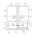
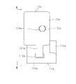
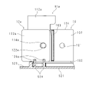
- FIG. 5 is a diagram showing the positional relationship between the busbars 11a and the heat absorbing members 12a in the electric connection box 100 according to the first embodiment
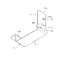
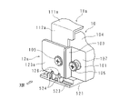
- FIG. 6 is a perspective view showing the positional relationship between the busbars 11a and the heat absorbing members 12a.
- FIG. 7 is a view taken along line VII--VII of FIG. 5 to 7 show only the busbar 11a and the heat absorbing member 12a for convenience.
- the contact portion 112a of the busbar 11a is arranged adjacent to the side surface 107 of the relay 10, and one surface faces the side surface 107.
- a heat absorbing member 12a is attached to the other surface of the contact portion 112a.
- the heat absorption member 12a is made of a plate material made of metal such as Al or Cu, and may be made of the same material as the busbar 11a.
- the heat absorbing member 12a has a rectangular rectangular plate 123a extending in the vertical direction.
- the rectangular plate 123a is shorter in vertical dimension than the contact portion 112a and longer in horizontal dimension than the contact portion 112a.
- the rectangular plate 123a has a through-hole 122a (corresponding through-hole) penetrating in the thickness direction at substantially the center in the vertical direction.
- an engaging portion 121a that engages with the contact portion 112a is continuously provided at a substantially central portion of one of the short sides of the rectangular plate 123a on the side of the flat portion 111a.
- the engaging portion 121a has an L-shape when viewed in longitudinal section. That is, the engaging portion 121a has a strip shape, and the tip thereof is bent toward the contact portion 112a. The tip of the engaging portion 121a is engaged with the rectangular through hole 116a of the contact portion 112a.
- the tip of the engaging portion 121a is rectangular in cross section, and the rectangular through hole 116a of the contact portion 112a has a shape that follows the tip of the engaging portion 121a. As shown in FIGS. 5 to 7, the tip of the engaging portion 121a is inserted into the rectangular through hole 116a, and the engaging portion 121a (heat absorption member 12a) engages with the contact portion 112a.
- the position of the heat absorbing member 12a with respect to the contact portion 112a is determined. That is, when the engaging portion 121a engages with the contact portion 112a (rectangular through-hole 116a), the other short side of the rectangular plate 123a is aligned with the short side of the contact portion 112a, and the through-hole 122a of the rectangular plate 123a is aligned with the short side of the contact portion 112a. , and the position of the through hole 114a of the contact portion 112a (see FIG. 5).
- the heat absorbing member 12a and the contact portion 112a are fixed to the terminal 101 by inserting the bolt 105 through the through hole 122a and the through hole 114a and screwing the bolt 105 to the terminal 101.
- Bus bar 11a is electrically connected to terminal 101 of relay 10, and heat absorbing member 12a is in pressure contact with bus bar 11a.
- the heat absorbing member 12b has a rectangular plate 123b and an engaging portion 121b. As shown in FIG. 4, the tip of the engaging portion 121b is inserted into the rectangular through hole 116b of the contact portion 112b, and the engaging portion 121b (heat absorption member 12b) is engaged with the contact portion 112b. At this time, the through hole (not shown) of the rectangular plate 123b and the through hole (not shown) of the contact portion 112b are aligned, and the bolt 105 is inserted into the through hole of the rectangular plate 123b and the through hole of the contact portion 112b. The heat absorbing member 12b and the contact portion 112b (bus bar 11b) are screwed to the relay 10 by being inserted and screwed with the terminal 101 (see FIG. 4).
- the through hole 122a of the rectangular plate 123a and the through hole 114a of the contact portion 112a are engaged with the engaging portions 121a and 121b of the heat absorbing members 12a and 12b and the rectangular through holes 116a and 116b of the contact portions 112a and 112b. are aligned, and the through hole of the rectangular plate 123b and the through hole of the contact portion 112b are aligned.
- the heat of the relay 10 absorbed by the heat absorbing members 12a and 12b is air-cooled through the surfaces of the heat absorbing members 12a and 12b. Therefore, unevenness may be formed on the surfaces of the heat absorbing members 12a and 12b that are not in contact with the contact portions 112a and 112b. In this case, since the areas of the heat absorbing members 12a and 12b that come into contact with the air become wider, the heat stored in the heat absorbing members 12a and 12b is cooled more efficiently.
- the relay 10 is used as an example of an electronic component that generates heat during operation, but the electronic component is not limited to this.
- the present invention can also be applied to other electronic components such as semiconductor switches.
- the electrical connection box 100 includes bus bars 11a and 11b and heat absorbing members 12a and 12b, as in the first embodiment.
- the heat absorption members 12a and 12b have substantially the same shape, and the positional relationship between the busbar 11a and the heat absorption member 12a is the same as the positional relationship between the busbar 11b and the heat absorption member 12b. 8-10, the busbar 11a and the heat absorbing member 12a will be described as an example, and the description of the busbar 11b and the heat absorbing member 12b will be omitted.
- the bus bar 11a is formed with an engaging hole 117a (engaging through hole) that engages with the heat absorbing member 12a.
- the engagement hole 117a is formed from the flat portion 111a to the contact portion 112a. That is, from the end portion of the flat portion 111a closer to the contact portion 112a to the end portion of the contact portion 112a closer to the flat portion 111a, the central portion in the width direction of the flat portion 111a and the contact portion 112a is notched into a substantially rectangular shape.
- a joint hole 117a is formed. Further, as in the first embodiment, a heat absorbing member 12a is attached to the other surface of the contact portion 112a of the busbar 11a.
- the heat absorbing member 12a has a rectangular rectangular plate 123a extending in the vertical direction.
- the rectangular plate 123a is shorter in vertical dimension than the contact portion 112a and longer in horizontal dimension than the contact portion 112a.
- the rectangular plate 123a has a through hole 122a penetrating in the thickness direction at substantially the center in the vertical direction.
- the operator engages the engaging portion 125a with the contact portion 112a (notch 118a) to close the through hole 122a and the contact portion 112a of the rectangular plate 123a. align the through holes 114a.
- the worker inserts the bolt 105 into the through hole 122a of the rectangular plate 123a and the through hole 114a of the contact portion 112a, and screws the bolt 105 to the corresponding terminal 101. As shown in FIG.
- the heat absorbing member 12a has a rectangular rectangular plate 123a.
- the rectangular plate 123a is shorter in vertical dimension than the contact portion 112a and longer in horizontal dimension than the contact portion 112a.
- the rectangular plate 123a has a through-hole 122a penetrating in the thickness direction at substantially the center in the vertical direction (see FIG. 14).
- two engagement recesses 126a that engage with the engagement strips 524 of the bottom plate 521 are formed in the edge portion near the bottom plate 521 (see FIGS. 14 and 15).
- Each engaging recess 126a is rectangular, and two engaging recesses 126a are formed at a predetermined interval.
- the position of the engaging recess 126a of the heat absorbing member 12a corresponds to the position of the engaging recess 119a of the contact portion 112a.
- each engaging strip 524 is projected from the inner surface 523 of the bottom plate 521 to engage with the engaging recess 126a of the heat absorbing member 12a and the engaging recess 119a of the contact portion 112a.
- Each engaging strip 524 is formed at a position corresponding to the engaging concave portion 126a of the heat absorbing member 12a and the engaging concave portion 119a of the contact portion 112a in the longitudinal direction. extending along.
- each engagement line 524 has a substantially elongated rectangular shape in a cross-sectional view, and a chamfered end portion is applied.
- the engagement strip 524 is integrally formed with the bottom plate 521 .
- each engagement strip 524 engages with the engagement recess 126a of the heat absorbing member 12a and the engagement recess 119a of the contact portion 112a, as shown in FIG. It matches the position of the through hole 114a of 112a.
- the heat generated in the relay 10 when energized is quickly absorbed by the heat absorbing member 12a through the contact portion 112a, and the temperature of the relay 10 and the contact portion 112a rises excessively. can be suppressed.
Landscapes
- Engineering & Computer Science (AREA)
- Microelectronics & Electronic Packaging (AREA)
- Mechanical Engineering (AREA)
- Physics & Mathematics (AREA)
- Thermal Sciences (AREA)
- Architecture (AREA)
- Civil Engineering (AREA)
- Structural Engineering (AREA)
- Connection Or Junction Boxes (AREA)
Abstract
Description
本出願は、2021年3月10日出願の日本出願第2021-038630号及び2021年8月26日出願の日本出願第2021-138136号に基づく優先権を主張し、前記日本出願に記載された全ての記載内容を援用するものである。
ところで、電気接続箱の電子部品には作動中に高い熱が発生するものが含まれる。斯かる電子部品で発生した熱は自部品の誤動作の原因になるうえに、周りの電子部品にも悪影響を与え得るので、抑制する必要がある。
本開示の一態様によれば、熱吸収部材を用いて簡単、且つ効果的に電子部品での熱上昇を抑制しつつ、組み立ての作業性を高めることができる電気接続箱を提供できる。
最初に本開示の実施態様を列挙して説明する。また、以下に記載する実施形態の少なくとも一部を任意に組み合わせてもよい。
よって、前記熱吸収部材が速やかに前記電子部品から熱を吸収できるうえ、組み立ての作業性を高めることができる。
よって、前記熱吸収部材が速やかに前記電子部品から熱を吸収できるうえ、組み立ての作業性を高めることができる。
よって、組み立ての作業性を更に高めることができる。
よって、作業者は容易に前記係合部を前記切り欠きと係合させることができ、組み立ての作業性を一層高めることができる。
本発明をその実施形態を示す図面に基づいて具体的に説明する。本開示の実施形態に係る電気接続箱を、以下に図面を参照しつつ説明する。なお、本発明はこれらの例示に限定されるものではなく、請求の範囲によって示され、請求の範囲と均等の意味及び範囲内でのすべての変更が含まれることが意図される。
図1は、実施形態1に係る電気接続箱100を示す斜視図である。電気接続箱100は、電子部品を収容する収容筐体50を備えている。収容筐体50は、例えば金属又は樹脂からなり、後述するリレー10が収容されている。
電気接続箱100では、収容筐体50が、リレー10が固定されるアッパーケース51と、アッパーケース51によって覆われる、ロウアーケース52とからなる。電気接続箱100は、例えば、EV(Electric Vehicle)の電池パックに取り付けられる。電気接続箱100は、ロウアーケース52の底板521がEVの電池パックと接触するように取り付けられる。
図8は、実施形態2に係る電気接続箱100におけるバスバー11a及び熱吸収部材12aの位置関係を示す図であり、図9は、バスバー11a及び熱吸収部材12aの位置関係を示す斜視図であり、図10は、図8のX-X線による矢視図である。図8-図10においては、便宜上、バスバー11a及び熱吸収部材12aのみを示している。
図11は、実施形態3に係る電気接続箱100におけるバスバー11a及び熱吸収部材12aの位置関係を示す図であり、図12は、バスバー11a及び熱吸収部材12aの位置関係を示す斜視図である。図11-図12においては、便宜上、バスバー11a及び熱吸収部材12aのみを示している。
また、実施形態1と同様、バスバー11aの接触部112aの他面に、熱吸収部材12aが取り付けられている。
図13は、実施形態4に係る電気接続箱100におけるバスバー11a及び熱吸収部材12aの位置関係を示す図であり、図14は、図13の矢印XIVによる矢視図であり、図15は、図14の熱吸収部材12aの位置をシフトさせた状態を示す図である。図13-図15においては、便宜上、リレー10、バスバー11a、熱吸収部材12a及び底板521の一部のみを示し、図14-図15では、便宜上、ボルト105を省略している。
また、実施形態1と同様、バスバー11aの接触部112aの他面に、熱吸収部材12aが取り付けられている。
11,11a,11b バスバー
12a,12b 熱吸収部材
13 押し付け部
50 収容筐体
51 アッパーケース
52 ロウアーケース
100 電気接続箱
101 端子
102 一面
103 仕切板
105 ボルト
107 側面
111a,111b 扁平部
112a,112b 接触部
114a 貫通孔
116a,116b 矩形貫通孔(係合貫通孔)
117a 係合孔(係合貫通孔)
118a 切り欠き
119a 係合凹部
121a,121b 係合部
122a 貫通孔(対応貫通孔)
123a,123b 矩形板
124a 係合部
125a 係合部
126a 係合凹部
513 天井板
521 底板
523 内側面
524 係合条
Claims (5)
- 一端部に貫通孔を有し、該貫通孔を用いて電子部品にネジ止めされるバスバーを備える車両用の電気接続箱であって、
前記一端部に取り付けられ、前記電子部品から熱を吸収する熱吸収部材を備え、
前記熱吸収部材は、
前記貫通孔に対応する対応貫通孔と、
前記バスバーと係合する係合部と
を有する電気接続箱。 - 前記バスバーは前記係合部と係合する係合貫通孔を有する請求項1に記載の電気接続箱。
- 前記係合部はフック形状をなす請求項1又は2に記載の電気接続箱。
- 前記バスバーの辺縁には、前記係合部と係合する切り欠きが形成されている請求項1に記載の電気接続箱。
- 前記熱吸収部材は、銅又はアルミニウムからなる請求項1から4のいずれか一項に記載の電気接続箱。
Priority Applications (2)
| Application Number | Priority Date | Filing Date | Title |
|---|---|---|---|
| CN202280019183.4A CN116941152A (zh) | 2021-03-10 | 2022-02-22 | 电连接箱 |
| US18/549,022 US20240149810A1 (en) | 2021-03-10 | 2022-02-22 | Electrical junction box |
Applications Claiming Priority (4)
| Application Number | Priority Date | Filing Date | Title |
|---|---|---|---|
| JP2021-038630 | 2021-03-10 | ||
| JP2021038630 | 2021-03-10 | ||
| JP2021138136A JP7647445B2 (ja) | 2021-03-10 | 2021-08-26 | 電気接続箱 |
| JP2021-138136 | 2021-08-26 |
Publications (1)
| Publication Number | Publication Date |
|---|---|
| WO2022190864A1 true WO2022190864A1 (ja) | 2022-09-15 |
Family
ID=83227708
Family Applications (1)
| Application Number | Title | Priority Date | Filing Date |
|---|---|---|---|
| PCT/JP2022/007334 Ceased WO2022190864A1 (ja) | 2021-03-10 | 2022-02-22 | 電気接続箱 |
Country Status (2)
| Country | Link |
|---|---|
| US (1) | US20240149810A1 (ja) |
| WO (1) | WO2022190864A1 (ja) |
Citations (2)
| Publication number | Priority date | Publication date | Assignee | Title |
|---|---|---|---|---|
| JPH09284951A (ja) * | 1996-04-08 | 1997-10-31 | Sumitomo Wiring Syst Ltd | 電気接続箱 |
| JP2006217736A (ja) * | 2005-02-03 | 2006-08-17 | Denso Corp | ブスバーの放熱プレートへの取り付け構造 |
Family Cites Families (3)
| Publication number | Priority date | Publication date | Assignee | Title |
|---|---|---|---|---|
| US6599137B2 (en) * | 2000-12-21 | 2003-07-29 | Lear Corporation | Combined eyelet terminal connector bracket and wire harness trough attachment tab |
| JP4970093B2 (ja) * | 2006-08-01 | 2012-07-04 | 矢崎総業株式会社 | 取付構造 |
| JP5465968B2 (ja) * | 2009-09-30 | 2014-04-09 | 矢崎総業株式会社 | バスバー及び電気接続箱 |
-
2022
- 2022-02-22 US US18/549,022 patent/US20240149810A1/en active Pending
- 2022-02-22 WO PCT/JP2022/007334 patent/WO2022190864A1/ja not_active Ceased
Patent Citations (2)
| Publication number | Priority date | Publication date | Assignee | Title |
|---|---|---|---|---|
| JPH09284951A (ja) * | 1996-04-08 | 1997-10-31 | Sumitomo Wiring Syst Ltd | 電気接続箱 |
| JP2006217736A (ja) * | 2005-02-03 | 2006-08-17 | Denso Corp | ブスバーの放熱プレートへの取り付け構造 |
Also Published As
| Publication number | Publication date |
|---|---|
| US20240149810A1 (en) | 2024-05-09 |
Similar Documents
| Publication | Publication Date | Title |
|---|---|---|
| KR101382793B1 (ko) | 정션박스용 인쇄회로기판의 열방출 장치 | |
| JP6287891B2 (ja) | 電気接続箱及び接続端子部品 | |
| JP7067527B2 (ja) | 回路構成体 | |
| CN107251349A (zh) | 电连接箱及连接端子部件 | |
| CN115244810B (zh) | 电气连接箱 | |
| KR100897091B1 (ko) | 회전방지 구조를 갖는 고전압 배터리용 배터리모듈 단자와버스바 | |
| WO2018207621A1 (ja) | 回路構成体及び電気接続箱 | |
| JPWO2021059767A5 (ja) | ||
| JP2022140229A (ja) | 電気接続箱 | |
| WO2017073258A1 (ja) | 蓄電ユニット | |
| WO2022190864A1 (ja) | 電気接続箱 | |
| JP6951989B2 (ja) | 電気接続箱 | |
| JP7654327B2 (ja) | 通電制御装置 | |
| CN116941152A (zh) | 电连接箱 | |
| JP7024704B2 (ja) | 電子モジュール | |
| US12580369B2 (en) | Electric junction box | |
| CN113170599B (zh) | 电子模块 | |
| US12573822B2 (en) | Electric junction box | |
| JP7775737B2 (ja) | 電気接続箱 | |
| US20250118951A1 (en) | Electrical junction box | |
| JP6780378B2 (ja) | 電池モジュール | |
| JP7779399B2 (ja) | 電気接続箱 | |
| JP2022119554A (ja) | 電気接続箱 | |
| JP2025159801A (ja) | 電気接続ユニット | |
| WO2024058184A1 (ja) | 電気接続箱 |
Legal Events
| Date | Code | Title | Description |
|---|---|---|---|
| 121 | Ep: the epo has been informed by wipo that ep was designated in this application |
Ref document number: 22766826 Country of ref document: EP Kind code of ref document: A1 |
|
| WWE | Wipo information: entry into national phase |
Ref document number: 18549022 Country of ref document: US Ref document number: 202280019183.4 Country of ref document: CN |
|
| NENP | Non-entry into the national phase |
Ref country code: DE |
|
| 122 | Ep: pct application non-entry in european phase |
Ref document number: 22766826 Country of ref document: EP Kind code of ref document: A1 |