WO2022190555A1 - ガス分析装置 - Google Patents
ガス分析装置 Download PDFInfo
- Publication number
- WO2022190555A1 WO2022190555A1 PCT/JP2021/047224 JP2021047224W WO2022190555A1 WO 2022190555 A1 WO2022190555 A1 WO 2022190555A1 JP 2021047224 W JP2021047224 W JP 2021047224W WO 2022190555 A1 WO2022190555 A1 WO 2022190555A1
- Authority
- WO
- WIPO (PCT)
- Prior art keywords
- gas
- cell
- optical
- gas cell
- surface plate
- Prior art date
- Legal status (The legal status is an assumption and is not a legal conclusion. Google has not performed a legal analysis and makes no representation as to the accuracy of the status listed.)
- Ceased
Links
Images




Classifications
-
- G—PHYSICS
- G01—MEASURING; TESTING
- G01N—INVESTIGATING OR ANALYSING MATERIALS BY DETERMINING THEIR CHEMICAL OR PHYSICAL PROPERTIES
- G01N21/00—Investigating or analysing materials by the use of optical means, i.e. using sub-millimetre waves, infrared, visible or ultraviolet light
- G01N21/84—Systems specially adapted for particular applications
- G01N21/85—Investigating moving fluids or granular solids
- G01N21/8507—Probe photometers, i.e. with optical measuring part dipped into fluid sample
-
- G—PHYSICS
- G01—MEASURING; TESTING
- G01N—INVESTIGATING OR ANALYSING MATERIALS BY DETERMINING THEIR CHEMICAL OR PHYSICAL PROPERTIES
- G01N21/00—Investigating or analysing materials by the use of optical means, i.e. using sub-millimetre waves, infrared, visible or ultraviolet light
- G01N21/17—Systems in which incident light is modified in accordance with the properties of the material investigated
- G01N21/25—Colour; Spectral properties, i.e. comparison of effect of material on the light at two or more different wavelengths or wavelength bands
- G01N21/31—Investigating relative effect of material at wavelengths characteristic of specific elements or molecules, e.g. atomic absorption spectrometry
- G01N21/35—Investigating relative effect of material at wavelengths characteristic of specific elements or molecules, e.g. atomic absorption spectrometry using infrared light
- G01N21/3504—Investigating relative effect of material at wavelengths characteristic of specific elements or molecules, e.g. atomic absorption spectrometry using infrared light for analysing gases, e.g. multi-gas analysis
-
- G—PHYSICS
- G01—MEASURING; TESTING
- G01N—INVESTIGATING OR ANALYSING MATERIALS BY DETERMINING THEIR CHEMICAL OR PHYSICAL PROPERTIES
- G01N21/00—Investigating or analysing materials by the use of optical means, i.e. using sub-millimetre waves, infrared, visible or ultraviolet light
- G01N21/01—Arrangements or apparatus for facilitating the optical investigation
- G01N21/03—Cuvette constructions
- G01N21/0303—Optical path conditioning in cuvettes, e.g. windows; adapted optical elements or systems; path modifying or adjustment
-
- G—PHYSICS
- G01—MEASURING; TESTING
- G01N—INVESTIGATING OR ANALYSING MATERIALS BY DETERMINING THEIR CHEMICAL OR PHYSICAL PROPERTIES
- G01N21/00—Investigating or analysing materials by the use of optical means, i.e. using sub-millimetre waves, infrared, visible or ultraviolet light
- G01N21/01—Arrangements or apparatus for facilitating the optical investigation
- G01N21/03—Cuvette constructions
- G01N21/05—Flow-through cuvettes
-
- G—PHYSICS
- G01—MEASURING; TESTING
- G01N—INVESTIGATING OR ANALYSING MATERIALS BY DETERMINING THEIR CHEMICAL OR PHYSICAL PROPERTIES
- G01N21/00—Investigating or analysing materials by the use of optical means, i.e. using sub-millimetre waves, infrared, visible or ultraviolet light
- G01N21/17—Systems in which incident light is modified in accordance with the properties of the material investigated
- G01N21/59—Transmissivity
- G01N21/61—Non-dispersive gas analysers
-
- G—PHYSICS
- G01—MEASURING; TESTING
- G01N—INVESTIGATING OR ANALYSING MATERIALS BY DETERMINING THEIR CHEMICAL OR PHYSICAL PROPERTIES
- G01N21/00—Investigating or analysing materials by the use of optical means, i.e. using sub-millimetre waves, infrared, visible or ultraviolet light
- G01N21/17—Systems in which incident light is modified in accordance with the properties of the material investigated
- G01N21/25—Colour; Spectral properties, i.e. comparison of effect of material on the light at two or more different wavelengths or wavelength bands
- G01N21/31—Investigating relative effect of material at wavelengths characteristic of specific elements or molecules, e.g. atomic absorption spectrometry
- G01N21/35—Investigating relative effect of material at wavelengths characteristic of specific elements or molecules, e.g. atomic absorption spectrometry using infrared light
- G01N21/3504—Investigating relative effect of material at wavelengths characteristic of specific elements or molecules, e.g. atomic absorption spectrometry using infrared light for analysing gases, e.g. multi-gas analysis
- G01N2021/3513—Open path with an instrumental source
-
- G—PHYSICS
- G01—MEASURING; TESTING
- G01N—INVESTIGATING OR ANALYSING MATERIALS BY DETERMINING THEIR CHEMICAL OR PHYSICAL PROPERTIES
- G01N21/00—Investigating or analysing materials by the use of optical means, i.e. using sub-millimetre waves, infrared, visible or ultraviolet light
- G01N21/17—Systems in which incident light is modified in accordance with the properties of the material investigated
- G01N21/25—Colour; Spectral properties, i.e. comparison of effect of material on the light at two or more different wavelengths or wavelength bands
- G01N21/31—Investigating relative effect of material at wavelengths characteristic of specific elements or molecules, e.g. atomic absorption spectrometry
- G01N21/35—Investigating relative effect of material at wavelengths characteristic of specific elements or molecules, e.g. atomic absorption spectrometry using infrared light
- G01N2021/3595—Investigating relative effect of material at wavelengths characteristic of specific elements or molecules, e.g. atomic absorption spectrometry using infrared light using FTIR
-
- G—PHYSICS
- G01—MEASURING; TESTING
- G01N—INVESTIGATING OR ANALYSING MATERIALS BY DETERMINING THEIR CHEMICAL OR PHYSICAL PROPERTIES
- G01N21/00—Investigating or analysing materials by the use of optical means, i.e. using sub-millimetre waves, infrared, visible or ultraviolet light
- G01N21/17—Systems in which incident light is modified in accordance with the properties of the material investigated
- G01N21/25—Colour; Spectral properties, i.e. comparison of effect of material on the light at two or more different wavelengths or wavelength bands
- G01N21/31—Investigating relative effect of material at wavelengths characteristic of specific elements or molecules, e.g. atomic absorption spectrometry
- G01N21/39—Investigating relative effect of material at wavelengths characteristic of specific elements or molecules, e.g. atomic absorption spectrometry using tunable lasers
- G01N2021/396—Type of laser source
- G01N2021/399—Diode laser
-
- G—PHYSICS
- G01—MEASURING; TESTING
- G01N—INVESTIGATING OR ANALYSING MATERIALS BY DETERMINING THEIR CHEMICAL OR PHYSICAL PROPERTIES
- G01N21/00—Investigating or analysing materials by the use of optical means, i.e. using sub-millimetre waves, infrared, visible or ultraviolet light
- G01N21/84—Systems specially adapted for particular applications
- G01N21/85—Investigating moving fluids or granular solids
- G01N2021/8557—Special shaping of flow, e.g. using a by-pass line, jet flow, curtain flow
-
- G—PHYSICS
- G01—MEASURING; TESTING
- G01N—INVESTIGATING OR ANALYSING MATERIALS BY DETERMINING THEIR CHEMICAL OR PHYSICAL PROPERTIES
- G01N21/00—Investigating or analysing materials by the use of optical means, i.e. using sub-millimetre waves, infrared, visible or ultraviolet light
- G01N21/84—Systems specially adapted for particular applications
- G01N21/85—Investigating moving fluids or granular solids
- G01N2021/8578—Gaseous flow
-
- G—PHYSICS
- G01—MEASURING; TESTING
- G01N—INVESTIGATING OR ANALYSING MATERIALS BY DETERMINING THEIR CHEMICAL OR PHYSICAL PROPERTIES
- G01N21/00—Investigating or analysing materials by the use of optical means, i.e. using sub-millimetre waves, infrared, visible or ultraviolet light
- G01N21/01—Arrangements or apparatus for facilitating the optical investigation
- G01N21/03—Cuvette constructions
- G01N21/031—Multipass arrangements
-
- G—PHYSICS
- G01—MEASURING; TESTING
- G01N—INVESTIGATING OR ANALYSING MATERIALS BY DETERMINING THEIR CHEMICAL OR PHYSICAL PROPERTIES
- G01N21/00—Investigating or analysing materials by the use of optical means, i.e. using sub-millimetre waves, infrared, visible or ultraviolet light
- G01N21/01—Arrangements or apparatus for facilitating the optical investigation
- G01N21/03—Cuvette constructions
- G01N21/0332—Cuvette constructions with temperature control
Definitions
- the present invention relates to gas analyzers.
- Patent Document 1 As a conventional gas analyzer, as shown in Patent Document 1, a gas introduced into a gas cell is irradiated with a laser beam and the laser beam transmitted through the gas is detected to analyze the measurement target component contained in the gas. A method using an infrared absorption method is known.
- the device configuration may be, for example, a stationary optical system in which a light source, a detector, an optical system, etc. are mounted on a single surface plate. housed in a cell.
- a gas cell may be attached to a pipe connected to the process chamber, for example, in order to grasp the state inside the process chamber as quickly as possible. Since the position of the gas analyzer varies depending on the installation, the posture of the gas analyzer after installation also varies.
- the above-mentioned problem is particularly conspicuous when a multi-reflection cell is used as the gas cell. This is because the angle of incidence of the laser light entering the gas cell of the multi-reflection cell must be adjusted to ⁇ 0.1 degrees or less, and a slight misalignment of the optical axis caused by the deflection of the surface plate can cause a drop in signal intensity. This is because the accuracy of the analysis cannot be guaranteed.
- the present invention has been made to solve the above-mentioned problems, and its main object is to reduce the moment in the gravitational direction that is generated with the mounting location or the like as a fulcrum, thereby suppressing the optical axis deviation as much as possible. It is something to do.
- the gas analyzer is a gas analyzer that irradiates a gas with a laser beam and detects the laser beam that has passed through the gas, thereby analyzing a measurement target component contained in the gas.
- a gas cell that is attached to the pipe through which the gas flows and into which the gas is introduced; and a long-sized gas cell that is connected to the gas cell from a predetermined connection direction and arranged on the optical path of the laser beam. and an elongated optical cell containing an optical system supported by a surface plate of the optical cell and the surface plate, wherein the optical cell and the surface plate are erected with respect to the connection direction.
- the optical cell and the surface plate are erected, for example, when the gas cell is attached to a vertically extending pipe, the conventional configuration in which the optical cell and the surface plate fall down is used.
- the distance from the mounting location of the gas cell to the center of gravity of the optical cell is shorter, and the gravitational moment generated with this mounting location as a fulcrum can be reduced, and optical axis deviation can be suppressed as much as possible.
- the optical system is arranged so that the optical path becomes three-dimensional, so the space inside the optical cell can be used efficiently, and the size and weight of the optical cell can be reduced. I can plan.
- the platen is arranged to face the gas cell.
- the surface plate can be brought closer to the gas cell side, so that the moment in the direction of gravity can be further reduced compared to the conventional configuration in which the surface plate is laid down.
- a gas analyzer is a gas analyzer that analyzes a measurement target component contained in the gas by irradiating the gas with a laser beam and detecting the laser beam that has passed through the gas.
- a gas cell that is attached to the pipe through which the gas flows and into which the gas is introduced; and a gas cell that is connected to the gas cell from a predetermined connection direction and is placed on the optical path of the laser beam and attached to the surface plate. and an elongated optical cell containing a supported optical system, wherein the platen is arranged to face the gas cell.
- the surface plate is arranged to face the gas cell.
- the distance from the gas cell attachment location to the center of gravity of the optical cell becomes shorter than in the conventional configuration in which the surface plate is laid down, and the gravity direction generated with this attachment location as the fulcrum becomes shorter. The moment can be reduced, and the optical axis deviation can be suppressed as much as possible.
- a light source for emitting the laser light a detector for detecting the laser light, and a light projecting side for guiding the laser light emitted from the light source to the gas cell.
- the optical system on the light-receiving side that guides the laser beam transmitted through the gas to the detector are supported by the surface plate.
- the optical cell in a configuration including a heating mechanism for heating the gas cell and a heat insulating material covering the gas cell, one end is connected to the optical cell, and the other end is positioned inside the heat insulating material. and a beam member connecting the optical cell and the gas cell.
- the optical cell and the gas cell are connected via the beam member, the influence on the optical axis due to the positional deviation of the peripheral members of the gas cell can be minimized while the temperature of the gas cell can be controlled. can be significantly smaller.
- the optical cell can be arranged at a distance from the gas cell, so that the thermal effect of the gas cell on the optical cell can be reduced.
- the optical cell is positioned with respect to the gas cell by positioning and attaching this beam member with respect to the gas cell. As a result, even if the beam member and the optical cell are removed from the gas cell, the adjustment of the optical system is not required, and the maintainability can be improved.
- the beam member has at least a higher heat insulating property than the surface plate.
- At least two reflecting mirrors for reflecting the laser light are provided as the optical system on the light projecting side that guides the laser light to the gas cell.
- the optical axis of the laser beam can be adjusted in an appropriate direction with high accuracy, so that the incident angle of the laser beam with respect to the gas cell can be set with high accuracy.
- an operation section for operating the adjustment mechanism faces the side opposite to the central portion of the optical cell.
- the gas cell is provided with a pair of reflecting mirrors inside to multiple-reflect the laser light, the moment reduction effect of the present invention can be exhibited more remarkably.
- the gas cell may be provided in a pipe connected to a chamber in which a semiconductor manufacturing process is performed.
- the optical cell is connected to the gas cell in a predetermined connection direction separately from the optical cell, and is supported by a surface plate while being arranged on the optical path of the laser beam. It is preferable that the optical system further includes a second optical cell containing an optical system, and the surface plate of the second optical cell is arranged to face the gas cell.
- the surface plate of the second optical cell is also arranged to face the gas cell, for example, the distance from the mounting position of the gas cell to the center of gravity of the second optical cell is shortened, and the gravity generated with this mounting position as a fulcrum. Directional moments can be reduced.
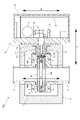
- FIG. 1 is a schematic diagram showing a semiconductor manufacturing apparatus incorporating a gas analyzer according to an embodiment of the present invention; FIG. The schematic diagram which shows the internal structure of the gas analyzer of the same embodiment.
- FIG. 2 is a schematic diagram showing the internal configuration of an optical cell in the gas analyzer of the same embodiment; The schematic diagram which shows the whole structure of the gas analyzer of the same embodiment.
- FIG. 1 is a schematic diagram showing the configuration of a conventional gas analyzer.
- the gas analyzer 100 of the present embodiment is used by being incorporated in a semiconductor manufacturing apparatus.
- gases include fluorides, chlorides, bromides, and the like.
- the gas analyzer 100 may measure components other than halides, and does not necessarily need to be incorporated into semiconductor manufacturing equipment.
- This gas analyzer 100 irradiates a gas with a laser beam and detects the laser beam that has passed through the gas, thereby analyzing the measurement target component contained in the gas by an infrared absorption method. Specifically, as shown in FIG. 1, it comprises a gas cell 1 into which gas is introduced and an optical cell 2 containing various optical systems arranged on the optical path of the laser beam.
- the gas cell 1 of the present embodiment guides a gas introduced into a chamber 200 in which a semiconductor manufacturing process is performed or a gas discharged from the chamber 200.
- the pipe H is provided with a pressure control valve CV for controlling the pressure of the chamber 200 and a vacuum pump CP for evacuating the chamber 200 in this order.
- the gas cell 1 is provided closer to the chamber 200 than the vacuum pump CP, the inlet port of the gas cell 1 is connected upstream of the pressure control valve CV, and the outlet port of the gas cell 1 is downstream of the pressure control valve CV. connected to the side.
- the pressure in the gas cell 1 is reduced to a predetermined pressure lower than the atmospheric pressure.
- the arrangement of the gas cell 1 is not limited to this.
- the inlet port may be connected downstream of the pressure control valve CV.
- the gas cell 1 is a multi-reflection cell that has a pair of reflection mirrors MR inside and multi-reflects laser light. Specifically, in this gas cell 1, a laser beam incident from one of the reflecting mirrors MR is multi-reflected and then exits from the same reflecting mirror MR.
- the mouth Lb is provided on the same side.
- a heating mechanism 3 such as a heater using a heating wire is provided around the gas cell 1 to heat the inside of the gas cell 1 to a predetermined temperature (eg, 200° C.).
- the optical cell 2 includes a light source 5 for irradiating the gas cell 1 with a laser beam, an optical system 6 provided on the optical path of the laser beam, and a laser beam passing through the gas. It comprises a photodetector 7, a signal processing unit 8 for calculating the concentration or partial pressure of a component to be measured using a light absorption signal obtained from the output signal of the photodetector 7, and a casing 9 for housing them.
- FIG. 3 in order to explain the internal structure of the optical cell 2, the illustration of the casing 9 and the like is omitted, and the orientation is different from that of FIG.
- the light source 5 is a laser tube that emits wavelength-modulated laser light, and oscillates mid-infrared (2.5 to 25 ⁇ m) laser light, for example.
- This light source 5 is capable of modulating the oscillation wavelength within a predetermined wavelength modulation range by a given current (or voltage). Other types may be used as long as the oscillation wavelength is variable, and the temperature may be changed to change the oscillation wavelength.
- the light source 5 may be a quantum cascade laser (QCL), which is a kind of semiconductor laser, and is not limited to emitting a wavelength-modulated laser beam, and emits a laser beam of a specific wavelength. It may be one that is ejected.
- QCL quantum cascade laser
- the light source 5 may be one that emits light of various wavelengths, such as one that emits infrared light or one that emits ultraviolet light. Various types of light sources may be used as long as they emit light, such as thermal light sources, LED light sources, deuterium lamps, and xenon lamps. When the multi-reflection cell described above is used as the gas cell, the light source 5 is preferably one that emits a laser beam that has a high intensity and is hard to attenuate even if it is reflected many times.
- the optical system 6 includes a projection-side optical system 6 (hereinafter also referred to as a projection-side optical system 61) that guides the laser beam emitted from the light source 5 to the gas cell 1, and a photodetector that detects the laser beam that has passed through the gas cell 1. 7 (also referred to as a light receiving side optical system 62 hereinafter) on the light receiving side.
- the light projecting optical system 61 is provided with at least two reflecting mirrors for reflecting laser light
- the light receiving optical system 62 is provided with at least two reflecting mirrors for reflecting laser light.
- three reflecting mirrors are provided as the light-projecting side optical system 61 and two reflecting mirrors are provided as the light-receiving side optical system 62. Specifically, these are plane mirrors or concave mirrors.
- the optical cell 2 of this embodiment also includes an adjustment mechanism 63 for adjusting the position or posture of the reflecting mirror, which is the optical system 6 described above.
- the adjustment mechanism 63 and the reflecting mirror are provided in one-to-one correspondence, and an operation unit 631 for the user to operate this adjustment mechanism 63 faces the side opposite to the central portion of the optical cell 2. , i.e. facing outward with the back to the central part.
- the photodetector 7 here uses a thermal type such as a thermopile which is relatively inexpensive, but other types, such as quantum type photoelectric devices such as HgCdTe, InGaAs, InAsSb, PbSe, etc., which have good responsiveness. An element may be used.
- a thermal type such as a thermopile which is relatively inexpensive, but other types, such as quantum type photoelectric devices such as HgCdTe, InGaAs, InAsSb, PbSe, etc., which have good responsiveness.
- An element may be used.
- the signal processing unit 8 includes an analog electric circuit including buffers, amplifiers, etc., a digital electric circuit including a CPU, memory, etc., and an AD converter, a DA converter, etc., which mediate between the analog/digital electric circuits.
- a light source control section for controlling the output of the light source 5 and outputs the output signal from the photodetector 7. It functions as a calculation unit that receives and calculates the concentration or partial pressure of the component to be measured by calculating the value.
- the casing 9 accommodates the various components described above and has an elongated shape. This is due to the fact that one or a plurality of component parts, such as the circuit board constituting the signal processing section 8, is elongated, and thus the optical cell 2 is also elongated.
- the casing 9 of this embodiment has a substantially rectangular parallelepiped shape, and one of the walls along its longitudinal direction is thicker than the other walls, and functions as a surface plate 10 that supports various components. is doing.
- the surface plate 10 supports at least the optical system 6 arranged on the optical path of the laser beam, and is in the shape of a long flat plate extending along the longitudinal direction of the optical cell 2 .
- the surface plate 10 of this embodiment supports the light-projecting side optical system 61 and the light-receiving side optical system 62 described above, and also supports the light source 5 and the photodetector 7 here. Supports most of the weight.
- the optical cell 2 configured in this way is connected to the gas cell 1 from a predetermined connection direction X, as shown in FIGS. More specifically, the connection direction X of the optical cell 2 and the gas cell 1 is a direction that intersects the flow direction Y of the gas introduced into the gas cell 1, that is, the axial direction Y of the pipe H to which the gas cell 1 is connected. , and is set in a direction perpendicular to the flow direction Y of the gas and the pipe axis direction Y of the pipe H here. That is, the optical cell 2 of this embodiment is horizontally connected to the gas cell 1 attached to the pipe H extending in the vertical direction.
- the optical cell 2 stands upright with respect to the connection direction X with the gas cell 1 .
- the state of standing in the connection direction X is a concept that includes not only the upright state (perpendicular to) the connection direction X, but also the state of being slightly tilted from the upright state. be.
- the optical cell 2 is connected to the gas cell 1 in such a manner that its longitudinal direction M intersects the connection direction X, and here the longitudinal direction M and the connection direction X are orthogonal.
- the laser tube which is the light source 5 described above, is arranged along the lateral direction N, the tube axis of which is perpendicular to the longitudinal direction M of the optical cell 2.
- the emission direction of the laser light immediately after being emitted from the light source 5 is the lateral direction N of the optical cell 2 . Since various types of light sources may be used as the light source 5 as described above, the emission direction from the light source 5 is not limited to the lateral direction N of the optical cell 2 either.
- the surface plate 10 described above is arranged to face the gas cell 1 . That is, the surface plate 10 is arranged closer to the gas cell 1 than the central portion of the entire optical cell 2 , and in this embodiment, the surface plate 10 is directly or indirectly connected to the gas cell 1 .
- the beam member 11 has one end connected to the optical cell 2 and the other end located inside the heat insulating material 4 and connected to the gas cell 1. More specifically, one end of the beam member 11 is an optical cell.
- the flange portion F2 on the cell 2 side is screwed to the surface plate 10, for example, and the flange portion F1 on the gas cell 1 side, which is the other end portion, is screwed to the wall surface of the gas cell 1, for example.
- a light passage hole Lc through which laser light passes is formed inside the beam member 11 .
- the beam member 11 has a higher heat insulating property than at least the surface plate 10, and is made of the same or different resin as the heat insulating material 4 described above. It is provided through the heat insulating material 4 so as to be positioned.
- the optical cell 2 is erected in the connection direction X, and the surface plate 10, which accounts for most of the total weight of the optical cell 2, is arranged on the gas cell 1 side. Therefore, for example, when the gas cell 1 is attached to the pipe H extending vertically, the distance from the attachment point of the gas cell 1 to the center of gravity of the optical cell 2 is greater than the conventional configuration in which the optical cell 2 is laid down. is shortened, the moment in the gravitational direction generated with this attachment point as a fulcrum can be reduced, and the optical axis deviation can be suppressed as much as possible.
- the gas cell 1 of this embodiment is a multi-reflection cell, and the incident angle of the laser light incident on the gas cell 1 must be adjusted within ⁇ 0.1 degrees. , the optical axis misalignment causes a signal error, so the above-described effect of reducing the moment is exhibited more remarkably.
- the optical system 6 is arranged such that the optical path becomes three-dimensional. You can also try to make it.
- the optical axis of the laser beam can be adjusted in an appropriate direction with high precision, so that the incident angle of the laser beam with respect to the gas cell 1 can be determined with high precision. can be set to
- the laser tube as the light source 5 is arranged so that its tube axis is along the lateral direction N of the optical cell 2, when the tube axis is arranged along the longitudinal direction M of the optical cell 2 , the longitudinal direction M of the optical cell 2 can be made compact.
- the adjustment mechanism 63 for adjusting the position or attitude of the optical system 6 is provided, it is possible to adjust the optical axis of the laser beam after assembly of the apparatus, and the operation part 631 can be used to move the outside of the optical cell 2. Because it is suitable, operability at the time of adjustment is good.
- a heating mechanism 3 for heating the gas cell 1 and a heat insulating material 4 surrounding the gas cell 1 are provided, it is possible to control the temperature of the gas cell 1 and prevent, for example, alteration of the gas to be measured. can be done.
- the peripheral structure of the gas cell 1 is complicated. Accumulation of misalignment of peripheral members may lead to misalignment of the optical axis, but in this embodiment, the gas cell 1 and the optical cell 2 are connected via the beam member 11, so the temperature of the gas cell 1 can be controlled. In spite of this configuration, it is possible to minimize the influence of the positional deviation of the peripheral members of the gas cell 1 on the optical axis.
- the optical cell 2 can be arranged at a distance from the gas cell 1, so that the thermal influence from the gas cell 1 to the optical cell 2 can be reduced. can be reduced. Moreover, if the optical cell 2 is previously positioned and attached to the beam member 11 , the optical cell 2 is positioned with respect to the gas cell 1 by positioning and attaching this beam member 11 with respect to the gas cell 1 . Accordingly, even if the beam member 11 and the optical cell 2 are removed from the gas cell 1, the optical system 6 does not need to be adjusted, and maintenance can be improved.
- the beam member 11 has a heat insulating property equivalent to that of the heat insulating material 4, the thermal effect of the gas cell 1 on the optical cell 2 can be more reliably reduced. It can also prevent decline. Furthermore, as the cross-sectional area of the beam member 11 is increased, the geometrical moment of inertia is increased, and the deflection of the beam member 11 can be reduced, thereby further reducing the optical axis deviation.
- the gas cell 1 and the optical cell 2 were connected by a single beam member 11 in the above embodiment, but may be connected by two or more beam members 11 as shown in FIG. .
- the thickness of the heat insulating material 4 can be increased, and the temperature control function can be further ensured.
- the gas analyzer 100 does not necessarily have a temperature control mechanism for the gas cell 1. 4 can be dispensed with.
- the gas cell 1 and the optical cell 2 may be directly connected without interposing the beam member 11 or the like.
- the single optical cell 2 is connected to the gas cell 1, but as shown in FIG. It's okay to be.
- the gas analyzer 100 according to the present invention is connected to the gas cell 1 in a predetermined connection direction separately from the optical cell 2, and is placed on the optical path of the laser beam.
- a second optical cell 2' containing a supported optical system may also be provided.
- one of the optical cell 2 and the second optical cell 2' accommodates the light source 5 and the light-projecting side optical system, and the other accommodates the photodetector 7 and the light-receiving side optical system. be able to.
- the optical cell 2 and the second optical cell 2' may be arranged so as to sandwich the gas cell 1, or as shown in FIG. 7(B),
- the connection direction of the optical cell 2 and the gas cell 1 and the connection direction of the second optical cell 2' and the gas cell 1 may be arranged so as to cross each other.
- the surface plate of the second optical cell 2' is arranged so as to face the gas cell 1.
- the specific shape of the second optical cell 2' may be a long shape such as a substantially rectangular parallelepiped shape, or a substantially cubic shape.
- the second optical cell 2 ′ is elongated, it is desirable that the second optical cell 2 ′ also stands upright with respect to the connecting direction of the gas cell 1 .
- the gas analyzer 100 uses a plurality of light sources 5 as shown in FIG.
- a plurality of optical paths for the laser light that passes through the gas and is guided to the photodetector 7 may be provided.
- one optical path can be made into a long optical path by multiple reflection as in the above embodiment, and the other optical path can be made into a short optical path that is shorter than the other optical path without multiple reflection.
- the surface plate 10 is arranged to face the gas cell 1.
- the surface plate 10 stands upright in the connection direction X between the gas cell 1 and the optical cell 2.
- the distance from the attachment point of the gas cell 1 or the like to the center of gravity of the optical cell 2 becomes shorter than in the conventional configuration in which the surface plate 10 is laid down. It is possible to reduce the moment in the direction of gravity generated with the attachment point as a fulcrum, and to suppress the optical axis deviation as much as possible.
- the disk 10 does not necessarily have to face the gas cell 1, for example, it is arranged on the side opposite to the gas cell 1.
- the gas cell 1 may have various shapes such as a substantially rectangular parallelepiped shape, a substantially cubic shape, and a substantially cylindrical shape, and the size (length) along the gas flow direction and the direction perpendicular thereto may be changed as appropriate. do not have.
- the gas analyzer 100 may be an analyzer using Fourier transform infrared spectroscopy (FTIR) or non-dispersive infrared absorption spectroscopy (NDIR), for example.
- FTIR Fourier transform infrared spectroscopy
- NDIR non-dispersive infrared absorption spectroscopy
- the present invention it is possible to reduce the moment in the gravitational direction that is generated with the mounting location or the like as the fulcrum, thereby suppressing the optical axis deviation as much as possible.
Landscapes
- Physics & Mathematics (AREA)
- Health & Medical Sciences (AREA)
- Life Sciences & Earth Sciences (AREA)
- Chemical & Material Sciences (AREA)
- Analytical Chemistry (AREA)
- Biochemistry (AREA)
- General Health & Medical Sciences (AREA)
- General Physics & Mathematics (AREA)
- Immunology (AREA)
- Pathology (AREA)
- Spectroscopy & Molecular Physics (AREA)
- Investigating Or Analysing Materials By Optical Means (AREA)
- Optical Measuring Cells (AREA)
Priority Applications (4)
| Application Number | Priority Date | Filing Date | Title |
|---|---|---|---|
| JP2023505115A JP7775278B2 (ja) | 2021-03-12 | 2021-12-21 | ガス分析装置 |
| US18/269,644 US12492989B2 (en) | 2021-03-12 | 2021-12-21 | Gas analyzing device |
| CN202180086309.5A CN116783467A (zh) | 2021-03-12 | 2021-12-21 | 气体分析装置 |
| KR1020237019771A KR20230151979A (ko) | 2021-03-12 | 2021-12-21 | 가스 분석 장치 |
Applications Claiming Priority (2)
| Application Number | Priority Date | Filing Date | Title |
|---|---|---|---|
| JP2021040603 | 2021-03-12 | ||
| JP2021-040603 | 2021-03-12 |
Publications (1)
| Publication Number | Publication Date |
|---|---|
| WO2022190555A1 true WO2022190555A1 (ja) | 2022-09-15 |
Family
ID=83226249
Family Applications (1)
| Application Number | Title | Priority Date | Filing Date |
|---|---|---|---|
| PCT/JP2021/047224 Ceased WO2022190555A1 (ja) | 2021-03-12 | 2021-12-21 | ガス分析装置 |
Country Status (6)
| Country | Link |
|---|---|
| US (1) | US12492989B2 (https=) |
| JP (1) | JP7775278B2 (https=) |
| KR (1) | KR20230151979A (https=) |
| CN (1) | CN116783467A (https=) |
| TW (1) | TWI911380B (https=) |
| WO (1) | WO2022190555A1 (https=) |
Citations (8)
| Publication number | Priority date | Publication date | Assignee | Title |
|---|---|---|---|---|
| JPS6150250U (https=) * | 1984-09-07 | 1986-04-04 | ||
| JP2007101433A (ja) * | 2005-10-06 | 2007-04-19 | Horiba Ltd | ガス分析装置 |
| JP2010217031A (ja) * | 2009-03-17 | 2010-09-30 | Shimadzu Corp | 光学式ガス分析システム及びガスフローセル |
| US20120287418A1 (en) * | 2010-10-14 | 2012-11-15 | Scherer James J | High-Accuracy Mid-IR Laser-Based Gas Sensor |
| JP2014105991A (ja) * | 2012-11-22 | 2014-06-09 | Shimadzu Corp | ガスセル |
| JP2015532433A (ja) * | 2012-10-18 | 2015-11-09 | ブイユーブイ・アナリティクス・インコーポレイテッドVUV Analytics,Inc. | 真空紫外吸収分光システムおよび方法 |
| JP2017504028A (ja) * | 2014-01-22 | 2017-02-02 | エイヴィエル エミッション テスト システムズ ゲゼルシャフト ミット ベシュレンクテル ハフツングAVL Emission Test Systems GmbH | 赤外吸収分光法を用いて試料ガス流中の少なくとも1つのガスの濃度を測定する装置 |
| JP2018084523A (ja) * | 2016-11-25 | 2018-05-31 | 株式会社島津製作所 | ガス濃度測定装置 |
Family Cites Families (9)
| Publication number | Priority date | Publication date | Assignee | Title |
|---|---|---|---|---|
| JPS6150250A (ja) * | 1984-08-17 | 1986-03-12 | Matsushita Electric Ind Co Ltd | タ−ンテ−ブル装置 |
| JP2004053405A (ja) * | 2002-07-19 | 2004-02-19 | Horiba Ltd | インラインガス分析計 |
| DK176920B1 (da) | 2008-10-30 | 2010-05-17 | Smidth As F L | Fremgangsmåde og apparat til analyse af partikelholdige gasser |
| JP2010190824A (ja) * | 2009-02-20 | 2010-09-02 | Shimadzu Corp | 半導体製造プロセス用吸光分析装置 |
| US9012851B2 (en) | 2010-10-14 | 2015-04-21 | Thermo Fisher Scientific (Bremen) Gmbh | Optical chamber module assembly |
| EP3644043B1 (en) * | 2011-12-27 | 2023-10-18 | HORIBA, Ltd. | Gas analyzing apparatus |
| WO2016174759A1 (ja) * | 2015-04-30 | 2016-11-03 | 富士電機株式会社 | レーザ式ガス分析計 |
| CN107024442A (zh) | 2015-12-15 | 2017-08-08 | 株式会社堀场制作所 | 多重反射型单元、分析装置、排气分析装置和光的射入方法 |
| JP2025050250A (ja) * | 2023-09-22 | 2025-04-04 | Toto株式会社 | 静電チャック |
-
2021
- 2021-12-21 CN CN202180086309.5A patent/CN116783467A/zh active Pending
- 2021-12-21 KR KR1020237019771A patent/KR20230151979A/ko active Pending
- 2021-12-21 WO PCT/JP2021/047224 patent/WO2022190555A1/ja not_active Ceased
- 2021-12-21 JP JP2023505115A patent/JP7775278B2/ja active Active
- 2021-12-21 US US18/269,644 patent/US12492989B2/en active Active
-
2022
- 2022-01-25 TW TW111103042A patent/TWI911380B/zh active
Patent Citations (8)
| Publication number | Priority date | Publication date | Assignee | Title |
|---|---|---|---|---|
| JPS6150250U (https=) * | 1984-09-07 | 1986-04-04 | ||
| JP2007101433A (ja) * | 2005-10-06 | 2007-04-19 | Horiba Ltd | ガス分析装置 |
| JP2010217031A (ja) * | 2009-03-17 | 2010-09-30 | Shimadzu Corp | 光学式ガス分析システム及びガスフローセル |
| US20120287418A1 (en) * | 2010-10-14 | 2012-11-15 | Scherer James J | High-Accuracy Mid-IR Laser-Based Gas Sensor |
| JP2015532433A (ja) * | 2012-10-18 | 2015-11-09 | ブイユーブイ・アナリティクス・インコーポレイテッドVUV Analytics,Inc. | 真空紫外吸収分光システムおよび方法 |
| JP2014105991A (ja) * | 2012-11-22 | 2014-06-09 | Shimadzu Corp | ガスセル |
| JP2017504028A (ja) * | 2014-01-22 | 2017-02-02 | エイヴィエル エミッション テスト システムズ ゲゼルシャフト ミット ベシュレンクテル ハフツングAVL Emission Test Systems GmbH | 赤外吸収分光法を用いて試料ガス流中の少なくとも1つのガスの濃度を測定する装置 |
| JP2018084523A (ja) * | 2016-11-25 | 2018-05-31 | 株式会社島津製作所 | ガス濃度測定装置 |
Also Published As
| Publication number | Publication date |
|---|---|
| JPWO2022190555A1 (https=) | 2022-09-15 |
| KR20230151979A (ko) | 2023-11-02 |
| TW202235853A (zh) | 2022-09-16 |
| US20240060881A1 (en) | 2024-02-22 |
| CN116783467A (zh) | 2023-09-19 |
| US12492989B2 (en) | 2025-12-09 |
| JP7775278B2 (ja) | 2025-11-25 |
| TWI911380B (zh) | 2026-01-11 |
Similar Documents
| Publication | Publication Date | Title |
|---|---|---|
| JP2022058585A (ja) | マルチパスサンプルセル | |
| US11519855B2 (en) | Close-coupled analyser | |
| JP6905992B2 (ja) | レーザ検出システム及び方法 | |
| CN107850535B (zh) | 气体监测仪 | |
| CN110325839B (zh) | 气体监测器 | |
| US20140183380A1 (en) | Measuring unit and gas analyzing apparatus | |
| US11630058B2 (en) | Concentration measurement device | |
| US10073028B2 (en) | Spectrometer optical head assembly | |
| JP2000019108A (ja) | 赤外線ガス分析計 | |
| JP5609580B2 (ja) | レーザガス分析計 | |
| CN110637225A (zh) | 光学传感器 | |
| JP7775278B2 (ja) | ガス分析装置 | |
| CN120898125A (zh) | 用于紧凑型光学气体吸收测量的设备 | |
| TW202248624A (zh) | 氣體分析裝置以及雷射光傳輸機構 | |
| TWI915556B (zh) | 氣體分析裝置以及雷射光傳輸機構 | |
| US12523603B2 (en) | Optical concentration measuring apparatus | |
| CN223898805U (zh) | 一种带参考光路的多波段激光芯片集成激光光源 | |
| JP2024085532A (ja) | ガス分析装置 | |
| CN118202225A (zh) | 粒子分析装置 | |
| JP2026513508A (ja) | コンパクトな光学的ガス吸収測定のための方法、装置、およびシステム | |
| KR20230172788A (ko) | 농도 측정 장치 | |
| TR2023005762U5 (tr) | Yakinsak nozullar i̇le tasarlanmiş opti̇k gaz sensörü |
Legal Events
| Date | Code | Title | Description |
|---|---|---|---|
| 121 | Ep: the epo has been informed by wipo that ep was designated in this application |
Ref document number: 21930400 Country of ref document: EP Kind code of ref document: A1 |
|
| ENP | Entry into the national phase |
Ref document number: 2023505115 Country of ref document: JP Kind code of ref document: A |
|
| WWE | Wipo information: entry into national phase |
Ref document number: 202180086309.5 Country of ref document: CN |
|
| WWE | Wipo information: entry into national phase |
Ref document number: 18269644 Country of ref document: US |
|
| NENP | Non-entry into the national phase |
Ref country code: DE |
|
| 122 | Ep: pct application non-entry in european phase |
Ref document number: 21930400 Country of ref document: EP Kind code of ref document: A1 |