WO2022190272A1 - 内視鏡用処置具およびクリップ装置 - Google Patents
内視鏡用処置具およびクリップ装置 Download PDFInfo
- Publication number
- WO2022190272A1 WO2022190272A1 PCT/JP2021/009575 JP2021009575W WO2022190272A1 WO 2022190272 A1 WO2022190272 A1 WO 2022190272A1 JP 2021009575 W JP2021009575 W JP 2021009575W WO 2022190272 A1 WO2022190272 A1 WO 2022190272A1
- Authority
- WO
- WIPO (PCT)
- Prior art keywords
- clip
- tightening member
- holding tube
- treatment tool
- tube
- Prior art date
- Legal status (The legal status is an assumption and is not a legal conclusion. Google has not performed a legal analysis and makes no representation as to the accuracy of the status listed.)
- Ceased
Links
Images














Classifications
-
- A—HUMAN NECESSITIES
- A61—MEDICAL OR VETERINARY SCIENCE; HYGIENE
- A61B—DIAGNOSIS; SURGERY; IDENTIFICATION
- A61B17/00—Surgical instruments, devices or methods
- A61B17/12—Surgical instruments, devices or methods for ligaturing or otherwise compressing tubular parts of the body, e.g. blood vessels or umbilical cord
- A61B17/128—Surgical instruments, devices or methods for ligaturing or otherwise compressing tubular parts of the body, e.g. blood vessels or umbilical cord for applying or removing clamps or clips
- A61B17/1285—Surgical instruments, devices or methods for ligaturing or otherwise compressing tubular parts of the body, e.g. blood vessels or umbilical cord for applying or removing clamps or clips for minimally invasive surgery
-
- A—HUMAN NECESSITIES
- A61—MEDICAL OR VETERINARY SCIENCE; HYGIENE
- A61B—DIAGNOSIS; SURGERY; IDENTIFICATION
- A61B17/00—Surgical instruments, devices or methods
- A61B17/00234—Surgical instruments, devices or methods for minimally invasive surgery
-
- A—HUMAN NECESSITIES
- A61—MEDICAL OR VETERINARY SCIENCE; HYGIENE
- A61B—DIAGNOSIS; SURGERY; IDENTIFICATION
- A61B17/00—Surgical instruments, devices or methods
- A61B17/12—Surgical instruments, devices or methods for ligaturing or otherwise compressing tubular parts of the body, e.g. blood vessels or umbilical cord
- A61B17/122—Clamps or clips, e.g. for the umbilical cord
-
- A—HUMAN NECESSITIES
- A61—MEDICAL OR VETERINARY SCIENCE; HYGIENE
- A61B—DIAGNOSIS; SURGERY; IDENTIFICATION
- A61B17/00—Surgical instruments, devices or methods
- A61B17/12—Surgical instruments, devices or methods for ligaturing or otherwise compressing tubular parts of the body, e.g. blood vessels or umbilical cord
- A61B17/122—Clamps or clips, e.g. for the umbilical cord
- A61B17/1227—Spring clips
-
- A—HUMAN NECESSITIES
- A61—MEDICAL OR VETERINARY SCIENCE; HYGIENE
- A61B—DIAGNOSIS; SURGERY; IDENTIFICATION
- A61B17/00—Surgical instruments, devices or methods
- A61B17/00234—Surgical instruments, devices or methods for minimally invasive surgery
- A61B2017/00292—Surgical instruments, devices or methods for minimally invasive surgery mounted on or guided by flexible, e.g. catheter-like, means
- A61B2017/00296—Surgical instruments, devices or methods for minimally invasive surgery mounted on or guided by flexible, e.g. catheter-like, means mounted on an endoscope
-
- A—HUMAN NECESSITIES
- A61—MEDICAL OR VETERINARY SCIENCE; HYGIENE
- A61B—DIAGNOSIS; SURGERY; IDENTIFICATION
- A61B17/00—Surgical instruments, devices or methods
- A61B17/00234—Surgical instruments, devices or methods for minimally invasive surgery
- A61B2017/00292—Surgical instruments, devices or methods for minimally invasive surgery mounted on or guided by flexible, e.g. catheter-like, means
- A61B2017/0034—Surgical instruments, devices or methods for minimally invasive surgery mounted on or guided by flexible, e.g. catheter-like, means adapted to be inserted through a working channel of an endoscope
-
- A—HUMAN NECESSITIES
- A61—MEDICAL OR VETERINARY SCIENCE; HYGIENE
- A61B—DIAGNOSIS; SURGERY; IDENTIFICATION
- A61B17/00—Surgical instruments, devices or methods
- A61B17/12—Surgical instruments, devices or methods for ligaturing or otherwise compressing tubular parts of the body, e.g. blood vessels or umbilical cord
- A61B2017/12004—Surgical instruments, devices or methods for ligaturing or otherwise compressing tubular parts of the body, e.g. blood vessels or umbilical cord for haemostasis, for prevention of bleeding
Definitions
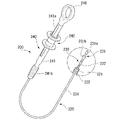
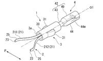
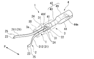
- the connecting portion 42 is an engaging portion with which the arrowhead hook portion 231 of the clip introducing device 200 is engaged (connected).
- the connecting portion 42 has a connecting portion main body 43 and an elastic arm portion 44 .
- the elastic arm portion 44 is provided at the proximal end of the connecting portion main body 43 and is bifurcated.
- the elastic arm portion 44 is elastically deformable with respect to the connecting portion main body 43 and can be opened and closed with respect to the connecting portion main body 43 .
- the elastic arm portion 44 is formed with a notch portion 44m for gripping and housing the engaging portion 231a of the arrowhead hook portion 231 .
- the notch portion 44m is formed in a shape that closely contacts the outer peripheral surface of the engaging portion 231a of the arrowhead hook portion 231. As shown in FIG.
- the clamping member 32 is formed in a ring shape, the clamping member 32 can be attached to the engaging portion 24 regardless of the shape of the pair of arms 21 in the closed state due to the shape of the tissue to be grasped. , and the pair of arms 21 can be reliably locked in the closed state.
- FIG. 12 shows the clip unit 1 with the clip 2 separated.
- the user further pulls the clip 2.
- a tensile breaking force amount of, for example, 20 N (Newton) to 90 N is applied to the hook 41f, and the hook 41f breaks.
- the user withdraws the sheath 220 and leaves the clip 2 with the tissue ligated in the body.
- FIG. 13 is a diagram showing the clip unit 1 after breaking.
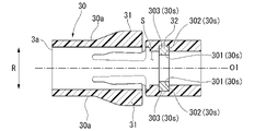
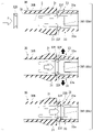
- the energy pulling the clip 2 toward the proximal side by the connecting member 4 no longer acts on the clip 2, and a force (impact load) acts to move the clip 2 toward the distal side. Since the third support surface 303 supports the tightening member 32 from the tip side even when an impact load is applied, the pair of arms 21 can be reliably maintained in the closed state.
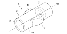
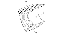
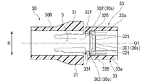
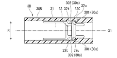
- the protruding wings 31 are a pair of protruding portions that protrude from the outer peripheral surface 30a of the hold down tube main body 30B, as in the first embodiment.
- the projecting wings 31 are provided on both sides of the center axis O1.
- the snap fit portion 33 is a pair of members provided on the pressing tube main body 30B.
- the snap fit portions 33 are provided on both sides of the center axis O1.
- the snap fit portion 33 has an elastic deformation portion 33a and a hook 33f.
- the hook 33f is provided at the tip end of the elastically deformable portion 33a, and is a convex portion protruding toward the inner region S side.
- the hook 33f fixes the tightening member 32B from the tip side.
- the snap fit portion 33 is provided at a position overlapping the protruding wing 31 in the circumferential direction C when viewed from the front in a direction horizontal to the central axis O1. From the viewpoint of the strength of the hold down tube main body 30B, the snap fit portion 33 may be provided at a position that does not overlap with the recessed wing 31 in the circumferential direction C in the front view.
- the clip unit 1B since the ring-shaped tightening member 32B is provided in the inner region S of the holding tube 3B, the clip 2 having a self-expanding force and which can be regrasped can be attached to the holding tube 3B. can be securely locked in the closed state.
- the fastening member 32B can be easily attached by the snap fit portion 33. Since the tightening member 32B is attached to the snap fit portion 33 from the distal end side, the tightening member 32B is not separated from the holding tube main body 30B when the engaging portion 24 is pulled from the tightening member 32B to the proximal end side.
- the tightening member 32B is attached by a snap fit portion 33 provided on the pressing tube 3B.
- the mounting manner of the tightening member 32B is not limited to this.
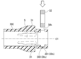
- 21 and 22 are cross-sectional views showing a hold-down tube 3C that is a modification of the hold-down tube 3B.
- the holding tube 3C has a holding tube main body 30B, a projecting wing 31, a tightening member 32B, and a hook 34.
- the hook 34 is a protrusion projecting inward in the radial direction R from the inner peripheral surface of the projecting wing 31 .
- the hooks 34 are provided on both sides of the center axis O1.
- the tightening member 32B is inserted to the mounting position by pushing the projecting wing 31 and the hook 34 outward in the radial direction R. As shown in FIG. When the clamping member 32B is inserted to the attachment position, the hook 34 returns to its original position to fix the clamping member 32B from the tip side. That is, the projecting wing 31 and the hook 34 function as the snap fit portion 33 of the above configuration.
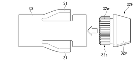
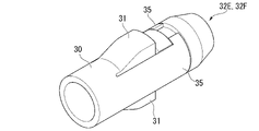
- the tip portion 32x has a ring portion 32r formed on the inner peripheral surface and a convex portion 32v formed on the outer peripheral surface.
- the ring portion 32 r has the same ring shape as the tightening member 32 and engages with the engaging portion 24 .
- the convex portion 32v is formed along the circumferential direction C and contacts the support surface 30s (the first support surface 301, the second support surface 302 and the third support surface 303).
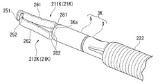
- FIG. 31 is a perspective view of a clip unit 1K according to this embodiment.
- FIG. 32 is a side view of the clip unit 1K.
- a clip unit (treatment instrument for an endoscope) 1K is used by loading it into a clip introduction device 200, like the clip unit 1 of the first embodiment.
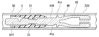
- the clip unit 1K includes a clip 2K, a pressing tube 3K, a connecting member 4K, and an elastic member 6.
- the clip 2K is formed by bending a metal plate material at the center like the clip 2 of the first embodiment.
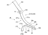
- the clip 2K has a pair of arms 21K that can be opened and closed, and a connecting portion 22K that connects the pair of arms 21K.
- the first arm 211K has a tissue grasping portion 251, a flat plate-like grasping portion 261, and a sliding portion 271 from the distal side to the proximal side.
- the second arm 212K has a tissue grasping portion 252, a flat plate-like grasping portion 262, and a sliding portion 272 from the distal side to the proximal side.
- the tissue gripping portion 251 is formed by bending the tip of the first arm 211K inward.
- the tissue grasping portion 252 is formed by bending the tip of the second arm 212K inward.
- the tissue gripping portion 251 and the tissue gripping portion 252 are formed in an asymmetrical shape with respect to the central axis O1. Therefore, when attaching the pair of arms 21K to the connecting member 4K, the user can easily grasp the direction in which the pair of arms 21K are attached to the connecting member 4K.
- FIG. 34 is an enlarged view of region R1 in FIG.
- the sliding portions 271 and 272 are portions that are elastically deformed when the pair of arms 21K are pulled into the pressing tube 3K.
- the sliding portions 271 and 272 have chamfered portions 271c and 272c whose ends are chamfered along the longitudinal direction on outer peripheral surfaces 271b and 272b on the outer side in the opening/closing direction P. As shown in FIG. Since the sliding portions 271 and 272 have the chamfered portions 271c and 272c, when the pair of arms 21K are pulled into the pressing tube 3K, they are less likely to get caught in the tip opening 3Ka of the pressing tube 3K.
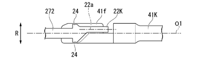
- FIG. 36 is a side view of the base ends of the pair of arms 21K.
- Engagement portions 24 projecting in a direction perpendicular to the central axis O1 are formed on the base end side of the first arm 211K and the base end side of the second arm 212K.
- the front end side of the engaging portion 24 is formed to have an acute slope
- the connecting portion 22 side of the engaging portion 24 is formed to have an obtuse slope.
- the engaging portion 24 is provided in a housing area T that is housed in the inner area S of the pressing tube 3K.
- the housing region T is a region that is always housed in the inner region S of the pressing tube 3K when the pair of arms 21K are opened and closed.
- the first arm 211K and the second arm 212K are connected by a connecting portion 22K on the base end side, and are provided so as to be openable and closable toward the tip end side.
- the connecting portion 22K is bent to have a U shape and is connected to the connecting member 4K.
- a tip opening 3Ka formed on the tip side of the holding pipe 5 engages with the sliding portions 271 and 272 of the pair of arms 21K.
- the tip opening 3Ka is freed from burrs by surface treatment such as magnetic barrel treatment, and is less likely to be caught by the sliding portions 271 and 272.
- the tip opening 3Ka may be subjected to a surface treatment such as nitriding to increase the surface hardness. By increasing the surface hardness of the tip opening 3Ka, the tip opening 3Ka is less likely to be caught by the sliding portions 271 and 272.
- the stopper 41r is a convex portion that protrudes outward in the radial direction R and is formed in a ring shape along the circumferential direction C.
- the stopper 41r engages with the proximal end of the pressing tube 3K. That is, the stopper 41r regulates the position where the connecting member 4K is pulled into the pressing tube 3K.
- FIG. 38 is a sectional view of the projecting wing 31.
- the projecting wing 31 is pressed by the inner peripheral surface of the sheath 220 and is in a recessed state.
- the projecting wing 31 has a first slope 31a, a second slope 32b, and a third slope 31c from the distal end side to the proximal end side.
- the first slope 31a, the second slope 32b, and the third slope 31c have different normal directions with respect to the central axis O1. Therefore, the retractable wing 31 is less likely to get caught on the sheath 220 .
- a reduced-diameter portion 220s having a smaller inner diameter than other portions is provided on the inner peripheral surface of the sheath 220 on the distal end side.
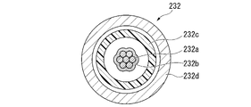
- An enlarged diameter portion 232s having a larger outer diameter than other portions is provided on the tip side of the wire 232 .
- the enlarged diameter portion 232s can pass through the reduced diameter portion 220s, but contacts the inner peripheral surface of the reduced diameter portion 220s during passage. Therefore, the advancing/retreating operation of the slider 242 in which the diameter-enlarged portion 232s passes through the diameter-reducing portion 220s requires a larger force than a normal advancing/retreating operation.
- the user can grasp that the expanded diameter portion 232s is passing through the reduced diameter portion 220s by feeling a load higher than usual when the slider 242 is moved back and forth.
- the diameter-reduced portion 220s and the diameter-enlarged portion 232s at appropriate positions, it is possible to prevent the user from moving the wire 232 to an unintended area.
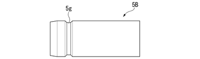
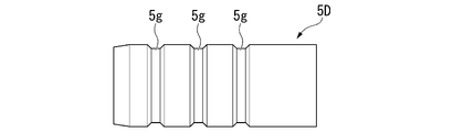
- (Modification 11) 41 to 43 are diagrams showing a holding pipe 5B, a holding pipe 5C, and a holding pipe 5D, which are modifications of the holding pipe 5.
- the pressing pipe 5B, the pressing pipe 5C, and the pressing pipe 5D have grooves 5g extending in the circumferential direction C on their outer peripheral surfaces.
- the holding pipe 5B, the holding pipe 5C, and the holding pipe 5D have different numbers of grooves 5g.
- a user can easily recognize the type of the clip unit 1K by using different holding pipes with different appearances for each type of the clip unit 1K.
- the present invention can be applied to endoscopic treatment tools such as clip units.
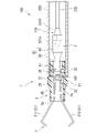
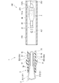
- clip device 100 clip device 200 clip introduction device 1, 1K clip unit (treatment tool for endoscope) 2, 2K Clips 21, 21K Pair of arms (plurality of arms) 24, 24K Engagement portion 3 Pressing tube 31 Protruding wing 30s Support surface 33 Snap fit portion 4, 4K Connecting member T Accommodation region S Internal region
Landscapes
- Health & Medical Sciences (AREA)
- Surgery (AREA)
- Life Sciences & Earth Sciences (AREA)
- Heart & Thoracic Surgery (AREA)
- Nuclear Medicine, Radiotherapy & Molecular Imaging (AREA)
- Engineering & Computer Science (AREA)
- Biomedical Technology (AREA)
- Medical Informatics (AREA)
- Molecular Biology (AREA)
- Animal Behavior & Ethology (AREA)
- General Health & Medical Sciences (AREA)
- Public Health (AREA)
- Veterinary Medicine (AREA)
- Vascular Medicine (AREA)
- Reproductive Health (AREA)
- Surgical Instruments (AREA)
Priority Applications (9)
| Application Number | Priority Date | Filing Date | Title |
|---|---|---|---|
| JP2023504974A JPWO2022190272A1 (cg-RX-API-DMAC7.html) | 2021-03-10 | 2021-03-10 | |
| PCT/JP2021/009575 WO2022190272A1 (ja) | 2021-03-10 | 2021-03-10 | 内視鏡用処置具およびクリップ装置 |
| DE112021006999.3T DE112021006999T5 (de) | 2021-03-10 | 2021-03-10 | Endoskop-behandlungswerkzeug und clip-vorrichtung |
| CN202180095329.9A CN116963678A (zh) | 2021-03-10 | 2021-03-10 | 内窥镜用处置器具及夹具装置 |
| US17/584,741 US11944321B2 (en) | 2021-01-26 | 2022-01-26 | Endoscopic treatment device |
| CN202210189581.2A CN115068013A (zh) | 2021-03-10 | 2022-02-28 | 内窥镜处置器具以及夹具装置 |
| CN202220412926.1U CN217471990U (zh) | 2021-03-10 | 2022-02-28 | 内窥镜处置器具以及夹具装置 |
| US18/462,880 US20230414225A1 (en) | 2021-03-10 | 2023-09-07 | Endoscopic treatment tool and clip device |
| US18/594,295 US12256942B2 (en) | 2021-01-26 | 2024-03-04 | Endoscopic treatment device |
Applications Claiming Priority (1)
| Application Number | Priority Date | Filing Date | Title |
|---|---|---|---|
| PCT/JP2021/009575 WO2022190272A1 (ja) | 2021-03-10 | 2021-03-10 | 内視鏡用処置具およびクリップ装置 |
Related Child Applications (1)
| Application Number | Title | Priority Date | Filing Date |
|---|---|---|---|
| US18/462,880 Continuation US20230414225A1 (en) | 2021-03-10 | 2023-09-07 | Endoscopic treatment tool and clip device |
Publications (1)
| Publication Number | Publication Date |
|---|---|
| WO2022190272A1 true WO2022190272A1 (ja) | 2022-09-15 |
Family
ID=83227621
Family Applications (1)
| Application Number | Title | Priority Date | Filing Date |
|---|---|---|---|
| PCT/JP2021/009575 Ceased WO2022190272A1 (ja) | 2021-01-26 | 2021-03-10 | 内視鏡用処置具およびクリップ装置 |
Country Status (5)
| Country | Link |
|---|---|
| US (1) | US20230414225A1 (cg-RX-API-DMAC7.html) |
| JP (1) | JPWO2022190272A1 (cg-RX-API-DMAC7.html) |
| CN (3) | CN116963678A (cg-RX-API-DMAC7.html) |
| DE (1) | DE112021006999T5 (cg-RX-API-DMAC7.html) |
| WO (1) | WO2022190272A1 (cg-RX-API-DMAC7.html) |
Families Citing this family (2)
| Publication number | Priority date | Publication date | Assignee | Title |
|---|---|---|---|---|
| CN116963678A (zh) * | 2021-03-10 | 2023-10-27 | 奥林巴斯医疗株式会社 | 内窥镜用处置器具及夹具装置 |
| CN121489659A (zh) * | 2026-01-12 | 2026-02-10 | 宁波市医疗中心李惠利医院(宁波大学附属李惠利医院) | 一种腹腔镜手术肿瘤标记定位用内镜磁定位夹 |
Citations (2)
| Publication number | Priority date | Publication date | Assignee | Title |
|---|---|---|---|---|
| JP2009022776A (ja) * | 2008-09-16 | 2009-02-05 | Olympus Corp | 生体組織の結紮装置 |
| WO2020095428A1 (ja) * | 2018-11-09 | 2020-05-14 | オリンパス株式会社 | クリップユニットおよび内視鏡クリップ |
Family Cites Families (4)
| Publication number | Priority date | Publication date | Assignee | Title |
|---|---|---|---|---|
| JP4472217B2 (ja) * | 2000-10-16 | 2010-06-02 | オリンパス株式会社 | 生体組織のクリップ装置 |
| JP4242614B2 (ja) * | 2002-08-21 | 2009-03-25 | オリンパス株式会社 | 生体組織の結紮装置 |
| JP4758173B2 (ja) * | 2004-12-24 | 2011-08-24 | オリンパス株式会社 | 結紮装置 |
| CN116963678A (zh) * | 2021-03-10 | 2023-10-27 | 奥林巴斯医疗株式会社 | 内窥镜用处置器具及夹具装置 |
-
2021
- 2021-03-10 CN CN202180095329.9A patent/CN116963678A/zh active Pending
- 2021-03-10 WO PCT/JP2021/009575 patent/WO2022190272A1/ja not_active Ceased
- 2021-03-10 JP JP2023504974A patent/JPWO2022190272A1/ja not_active Ceased
- 2021-03-10 DE DE112021006999.3T patent/DE112021006999T5/de active Pending
-
2022
- 2022-02-28 CN CN202210189581.2A patent/CN115068013A/zh active Pending
- 2022-02-28 CN CN202220412926.1U patent/CN217471990U/zh active Active
-
2023
- 2023-09-07 US US18/462,880 patent/US20230414225A1/en active Pending
Patent Citations (2)
| Publication number | Priority date | Publication date | Assignee | Title |
|---|---|---|---|---|
| JP2009022776A (ja) * | 2008-09-16 | 2009-02-05 | Olympus Corp | 生体組織の結紮装置 |
| WO2020095428A1 (ja) * | 2018-11-09 | 2020-05-14 | オリンパス株式会社 | クリップユニットおよび内視鏡クリップ |
Also Published As
| Publication number | Publication date |
|---|---|
| US20230414225A1 (en) | 2023-12-28 |
| JPWO2022190272A1 (cg-RX-API-DMAC7.html) | 2022-09-15 |
| DE112021006999T5 (de) | 2023-12-07 |
| CN116963678A (zh) | 2023-10-27 |
| CN217471990U (zh) | 2022-09-23 |
| CN115068013A (zh) | 2022-09-20 |
Similar Documents
| Publication | Publication Date | Title |
|---|---|---|
| JP5343113B2 (ja) | クリップユニット及びこれを用いる結紮装置 | |
| JP5427858B2 (ja) | 結紮装置、及び内視鏡システム | |
| JP2006158668A (ja) | 内視鏡用処置装置 | |
| JP5588711B2 (ja) | 結紮装置 | |
| JP5427857B2 (ja) | クリップユニット及びこれを用いた結紮装置、並びにクリップユニットの製造方法 | |
| JP7286743B2 (ja) | クリップデリバリデバイスおよびクリップユニット | |
| JP6663992B2 (ja) | 内視鏡処置具 | |
| JP6084347B1 (ja) | 内視鏡用処置具 | |
| JP4427070B2 (ja) | クリップケース | |
| WO2004017839A1 (ja) | 生体組織の結紮装置 | |
| CN101695452A (zh) | 结扎装置 | |
| US20230414225A1 (en) | Endoscopic treatment tool and clip device | |
| JP2004073646A (ja) | 生体組織の結紮装置 | |
| US12582405B2 (en) | Cartridge and cartridge system | |
| JP4472719B2 (ja) | 生体組織のクリップ装置 | |
| WO2015019781A1 (ja) | 縫合器 | |
| US12582406B2 (en) | Cartridge and cartridge system | |
| US20250000499A1 (en) | Clip device and clip system | |
| JP2007196012A (ja) | 生体組織のクリップ装置 | |
| US20240108355A1 (en) | Cartridge system, cartridge and method for loading clip unit | |
| JP2022179466A (ja) | クリップユニットおよびクリップアプリケータ | |
| JP4755234B2 (ja) | 生体組織の結紮装置 | |
| JP4472720B2 (ja) | 生体組織のクリップ装置 | |
| US20260090804A1 (en) | Clip device | |
| JP7474890B2 (ja) | クリップシステム、およびアプリケータ |
Legal Events
| Date | Code | Title | Description |
|---|---|---|---|
| 121 | Ep: the epo has been informed by wipo that ep was designated in this application |
Ref document number: 21930128 Country of ref document: EP Kind code of ref document: A1 |
|
| WWE | Wipo information: entry into national phase |
Ref document number: 202180095329.9 Country of ref document: CN |
|
| WWE | Wipo information: entry into national phase |
Ref document number: 2023504974 Country of ref document: JP |
|
| WWE | Wipo information: entry into national phase |
Ref document number: 202347062159 Country of ref document: IN |
|
| WWE | Wipo information: entry into national phase |
Ref document number: 112021006999 Country of ref document: DE |
|
| 122 | Ep: pct application non-entry in european phase |
Ref document number: 21930128 Country of ref document: EP Kind code of ref document: A1 |