WO2022190272A1 - Endoscopic treatment tool and clip device - Google Patents

Endoscopic treatment tool and clip device Download PDF

Info

Publication number
WO2022190272A1
WO2022190272A1 PCT/JP2021/009575 JP2021009575W WO2022190272A1 WO 2022190272 A1 WO2022190272 A1 WO 2022190272A1 JP 2021009575 W JP2021009575 W JP 2021009575W WO 2022190272 A1 WO2022190272 A1 WO 2022190272A1
Authority
WO
WIPO (PCT)
Prior art keywords
clip
tightening member
holding tube
treatment tool
tube
Prior art date
Application number
PCT/JP2021/009575
Other languages
French (fr)
Japanese (ja)
Inventor
健輔 上阪
一樹 秋吉
俊徳 田村
啓 青木
勉 岡田
Original Assignee
オリンパスメディカルシステムズ株式会社
Priority date (The priority date is an assumption and is not a legal conclusion. Google has not performed a legal analysis and makes no representation as to the accuracy of the date listed.)
Filing date
Publication date
Application filed by オリンパスメディカルシステムズ株式会社 filed Critical オリンパスメディカルシステムズ株式会社
Priority to CN202180095329.9A priority Critical patent/CN116963678A/en
Priority to PCT/JP2021/009575 priority patent/WO2022190272A1/en
Priority to JP2023504974A priority patent/JPWO2022190272A1/ja
Priority to DE112021006999.3T priority patent/DE112021006999T5/en
Priority to US17/584,741 priority patent/US11944321B2/en
Priority to CN202210189581.2A priority patent/CN115068013A/en
Priority to CN202220412926.1U priority patent/CN217471990U/en
Publication of WO2022190272A1 publication Critical patent/WO2022190272A1/en
Priority to US18/462,880 priority patent/US20230414225A1/en
Priority to US18/594,295 priority patent/US20240206883A1/en

Links

Images

Classifications

    • AHUMAN NECESSITIES
    • A61MEDICAL OR VETERINARY SCIENCE; HYGIENE
    • A61BDIAGNOSIS; SURGERY; IDENTIFICATION
    • A61B17/00Surgical instruments, devices or methods, e.g. tourniquets
    • A61B17/12Surgical instruments, devices or methods, e.g. tourniquets for ligaturing or otherwise compressing tubular parts of the body, e.g. blood vessels, umbilical cord
    • A61B17/128Surgical instruments, devices or methods, e.g. tourniquets for ligaturing or otherwise compressing tubular parts of the body, e.g. blood vessels, umbilical cord for applying or removing clamps or clips
    • A61B17/1285Surgical instruments, devices or methods, e.g. tourniquets for ligaturing or otherwise compressing tubular parts of the body, e.g. blood vessels, umbilical cord for applying or removing clamps or clips for minimally invasive surgery
    • AHUMAN NECESSITIES
    • A61MEDICAL OR VETERINARY SCIENCE; HYGIENE
    • A61BDIAGNOSIS; SURGERY; IDENTIFICATION
    • A61B17/00Surgical instruments, devices or methods, e.g. tourniquets
    • A61B17/00234Surgical instruments, devices or methods, e.g. tourniquets for minimally invasive surgery
    • AHUMAN NECESSITIES
    • A61MEDICAL OR VETERINARY SCIENCE; HYGIENE
    • A61BDIAGNOSIS; SURGERY; IDENTIFICATION
    • A61B17/00Surgical instruments, devices or methods, e.g. tourniquets
    • A61B17/12Surgical instruments, devices or methods, e.g. tourniquets for ligaturing or otherwise compressing tubular parts of the body, e.g. blood vessels, umbilical cord
    • A61B17/122Clamps or clips, e.g. for the umbilical cord
    • A61B17/1227Spring clips
    • AHUMAN NECESSITIES
    • A61MEDICAL OR VETERINARY SCIENCE; HYGIENE
    • A61BDIAGNOSIS; SURGERY; IDENTIFICATION
    • A61B17/00Surgical instruments, devices or methods, e.g. tourniquets
    • A61B17/00234Surgical instruments, devices or methods, e.g. tourniquets for minimally invasive surgery
    • A61B2017/00292Surgical instruments, devices or methods, e.g. tourniquets for minimally invasive surgery mounted on or guided by flexible, e.g. catheter-like, means
    • A61B2017/00296Surgical instruments, devices or methods, e.g. tourniquets for minimally invasive surgery mounted on or guided by flexible, e.g. catheter-like, means mounted on an endoscope
    • AHUMAN NECESSITIES
    • A61MEDICAL OR VETERINARY SCIENCE; HYGIENE
    • A61BDIAGNOSIS; SURGERY; IDENTIFICATION
    • A61B17/00Surgical instruments, devices or methods, e.g. tourniquets
    • A61B17/00234Surgical instruments, devices or methods, e.g. tourniquets for minimally invasive surgery
    • A61B2017/00292Surgical instruments, devices or methods, e.g. tourniquets for minimally invasive surgery mounted on or guided by flexible, e.g. catheter-like, means
    • A61B2017/0034Surgical instruments, devices or methods, e.g. tourniquets for minimally invasive surgery mounted on or guided by flexible, e.g. catheter-like, means adapted to be inserted through a working channel of an endoscope
    • AHUMAN NECESSITIES
    • A61MEDICAL OR VETERINARY SCIENCE; HYGIENE
    • A61BDIAGNOSIS; SURGERY; IDENTIFICATION
    • A61B17/00Surgical instruments, devices or methods, e.g. tourniquets
    • A61B17/12Surgical instruments, devices or methods, e.g. tourniquets for ligaturing or otherwise compressing tubular parts of the body, e.g. blood vessels, umbilical cord
    • A61B2017/12004Surgical instruments, devices or methods, e.g. tourniquets for ligaturing or otherwise compressing tubular parts of the body, e.g. blood vessels, umbilical cord for haemostasis, for prevention of bleeding

Definitions

  • the connecting portion 42 is an engaging portion with which the arrowhead hook portion 231 of the clip introducing device 200 is engaged (connected).
  • the connecting portion 42 has a connecting portion main body 43 and an elastic arm portion 44 .
  • the elastic arm portion 44 is provided at the proximal end of the connecting portion main body 43 and is bifurcated.
  • the elastic arm portion 44 is elastically deformable with respect to the connecting portion main body 43 and can be opened and closed with respect to the connecting portion main body 43 .
  • the elastic arm portion 44 is formed with a notch portion 44m for gripping and housing the engaging portion 231a of the arrowhead hook portion 231 .
  • the notch portion 44m is formed in a shape that closely contacts the outer peripheral surface of the engaging portion 231a of the arrowhead hook portion 231. As shown in FIG.
  • the clamping member 32 is formed in a ring shape, the clamping member 32 can be attached to the engaging portion 24 regardless of the shape of the pair of arms 21 in the closed state due to the shape of the tissue to be grasped. , and the pair of arms 21 can be reliably locked in the closed state.
  • FIG. 12 shows the clip unit 1 with the clip 2 separated.
  • the user further pulls the clip 2.
  • a tensile breaking force amount of, for example, 20 N (Newton) to 90 N is applied to the hook 41f, and the hook 41f breaks.
  • the user withdraws the sheath 220 and leaves the clip 2 with the tissue ligated in the body.
  • FIG. 13 is a diagram showing the clip unit 1 after breaking.
  • the energy pulling the clip 2 toward the proximal side by the connecting member 4 no longer acts on the clip 2, and a force (impact load) acts to move the clip 2 toward the distal side. Since the third support surface 303 supports the tightening member 32 from the tip side even when an impact load is applied, the pair of arms 21 can be reliably maintained in the closed state.
  • the protruding wings 31 are a pair of protruding portions that protrude from the outer peripheral surface 30a of the hold down tube main body 30B, as in the first embodiment.
  • the projecting wings 31 are provided on both sides of the center axis O1.
  • the snap fit portion 33 is a pair of members provided on the pressing tube main body 30B.
  • the snap fit portions 33 are provided on both sides of the center axis O1.
  • the snap fit portion 33 has an elastic deformation portion 33a and a hook 33f.
  • the hook 33f is provided at the tip end of the elastically deformable portion 33a, and is a convex portion protruding toward the inner region S side.
  • the hook 33f fixes the tightening member 32B from the tip side.
  • the snap fit portion 33 is provided at a position overlapping the protruding wing 31 in the circumferential direction C when viewed from the front in a direction horizontal to the central axis O1. From the viewpoint of the strength of the hold down tube main body 30B, the snap fit portion 33 may be provided at a position that does not overlap with the recessed wing 31 in the circumferential direction C in the front view.
  • the clip unit 1B since the ring-shaped tightening member 32B is provided in the inner region S of the holding tube 3B, the clip 2 having a self-expanding force and which can be regrasped can be attached to the holding tube 3B. can be securely locked in the closed state.
  • the fastening member 32B can be easily attached by the snap fit portion 33. Since the tightening member 32B is attached to the snap fit portion 33 from the distal end side, the tightening member 32B is not separated from the holding tube main body 30B when the engaging portion 24 is pulled from the tightening member 32B to the proximal end side.
  • the tightening member 32B is attached by a snap fit portion 33 provided on the pressing tube 3B.
  • the mounting manner of the tightening member 32B is not limited to this.
  • 21 and 22 are cross-sectional views showing a hold-down tube 3C that is a modification of the hold-down tube 3B.
  • the holding tube 3C has a holding tube main body 30B, a projecting wing 31, a tightening member 32B, and a hook 34.
  • the hook 34 is a protrusion projecting inward in the radial direction R from the inner peripheral surface of the projecting wing 31 .
  • the hooks 34 are provided on both sides of the center axis O1.
  • the tightening member 32B is inserted to the mounting position by pushing the projecting wing 31 and the hook 34 outward in the radial direction R. As shown in FIG. When the clamping member 32B is inserted to the attachment position, the hook 34 returns to its original position to fix the clamping member 32B from the tip side. That is, the projecting wing 31 and the hook 34 function as the snap fit portion 33 of the above configuration.
  • the tip portion 32x has a ring portion 32r formed on the inner peripheral surface and a convex portion 32v formed on the outer peripheral surface.
  • the ring portion 32 r has the same ring shape as the tightening member 32 and engages with the engaging portion 24 .
  • the convex portion 32v is formed along the circumferential direction C and contacts the support surface 30s (the first support surface 301, the second support surface 302 and the third support surface 303).
  • FIG. 31 is a perspective view of a clip unit 1K according to this embodiment.
  • FIG. 32 is a side view of the clip unit 1K.
  • a clip unit (treatment instrument for an endoscope) 1K is used by loading it into a clip introduction device 200, like the clip unit 1 of the first embodiment.
  • the clip unit 1K includes a clip 2K, a pressing tube 3K, a connecting member 4K, and an elastic member 6.
  • the clip 2K is formed by bending a metal plate material at the center like the clip 2 of the first embodiment.
  • the clip 2K has a pair of arms 21K that can be opened and closed, and a connecting portion 22K that connects the pair of arms 21K.
  • the first arm 211K has a tissue grasping portion 251, a flat plate-like grasping portion 261, and a sliding portion 271 from the distal side to the proximal side.
  • the second arm 212K has a tissue grasping portion 252, a flat plate-like grasping portion 262, and a sliding portion 272 from the distal side to the proximal side.
  • the tissue gripping portion 251 is formed by bending the tip of the first arm 211K inward.
  • the tissue grasping portion 252 is formed by bending the tip of the second arm 212K inward.
  • the tissue gripping portion 251 and the tissue gripping portion 252 are formed in an asymmetrical shape with respect to the central axis O1. Therefore, when attaching the pair of arms 21K to the connecting member 4K, the user can easily grasp the direction in which the pair of arms 21K are attached to the connecting member 4K.
  • FIG. 34 is an enlarged view of region R1 in FIG.
  • the sliding portions 271 and 272 are portions that are elastically deformed when the pair of arms 21K are pulled into the pressing tube 3K.
  • the sliding portions 271 and 272 have chamfered portions 271c and 272c whose ends are chamfered along the longitudinal direction on outer peripheral surfaces 271b and 272b on the outer side in the opening/closing direction P. As shown in FIG. Since the sliding portions 271 and 272 have the chamfered portions 271c and 272c, when the pair of arms 21K are pulled into the pressing tube 3K, they are less likely to get caught in the tip opening 3Ka of the pressing tube 3K.
  • FIG. 36 is a side view of the base ends of the pair of arms 21K.
  • Engagement portions 24 projecting in a direction perpendicular to the central axis O1 are formed on the base end side of the first arm 211K and the base end side of the second arm 212K.
  • the front end side of the engaging portion 24 is formed to have an acute slope
  • the connecting portion 22 side of the engaging portion 24 is formed to have an obtuse slope.
  • the engaging portion 24 is provided in a housing area T that is housed in the inner area S of the pressing tube 3K.
  • the housing region T is a region that is always housed in the inner region S of the pressing tube 3K when the pair of arms 21K are opened and closed.
  • the first arm 211K and the second arm 212K are connected by a connecting portion 22K on the base end side, and are provided so as to be openable and closable toward the tip end side.
  • the connecting portion 22K is bent to have a U shape and is connected to the connecting member 4K.
  • a tip opening 3Ka formed on the tip side of the holding pipe 5 engages with the sliding portions 271 and 272 of the pair of arms 21K.
  • the tip opening 3Ka is freed from burrs by surface treatment such as magnetic barrel treatment, and is less likely to be caught by the sliding portions 271 and 272.
  • the tip opening 3Ka may be subjected to a surface treatment such as nitriding to increase the surface hardness. By increasing the surface hardness of the tip opening 3Ka, the tip opening 3Ka is less likely to be caught by the sliding portions 271 and 272.
  • the stopper 41r is a convex portion that protrudes outward in the radial direction R and is formed in a ring shape along the circumferential direction C.
  • the stopper 41r engages with the proximal end of the pressing tube 3K. That is, the stopper 41r regulates the position where the connecting member 4K is pulled into the pressing tube 3K.
  • FIG. 38 is a sectional view of the projecting wing 31.
  • the projecting wing 31 is pressed by the inner peripheral surface of the sheath 220 and is in a recessed state.
  • the projecting wing 31 has a first slope 31a, a second slope 32b, and a third slope 31c from the distal end side to the proximal end side.
  • the first slope 31a, the second slope 32b, and the third slope 31c have different normal directions with respect to the central axis O1. Therefore, the retractable wing 31 is less likely to get caught on the sheath 220 .
  • a reduced-diameter portion 220s having a smaller inner diameter than other portions is provided on the inner peripheral surface of the sheath 220 on the distal end side.
  • An enlarged diameter portion 232s having a larger outer diameter than other portions is provided on the tip side of the wire 232 .
  • the enlarged diameter portion 232s can pass through the reduced diameter portion 220s, but contacts the inner peripheral surface of the reduced diameter portion 220s during passage. Therefore, the advancing/retreating operation of the slider 242 in which the diameter-enlarged portion 232s passes through the diameter-reducing portion 220s requires a larger force than a normal advancing/retreating operation.
  • the user can grasp that the expanded diameter portion 232s is passing through the reduced diameter portion 220s by feeling a load higher than usual when the slider 242 is moved back and forth.
  • the diameter-reduced portion 220s and the diameter-enlarged portion 232s at appropriate positions, it is possible to prevent the user from moving the wire 232 to an unintended area.
  • (Modification 11) 41 to 43 are diagrams showing a holding pipe 5B, a holding pipe 5C, and a holding pipe 5D, which are modifications of the holding pipe 5.
  • the pressing pipe 5B, the pressing pipe 5C, and the pressing pipe 5D have grooves 5g extending in the circumferential direction C on their outer peripheral surfaces.
  • the holding pipe 5B, the holding pipe 5C, and the holding pipe 5D have different numbers of grooves 5g.
  • a user can easily recognize the type of the clip unit 1K by using different holding pipes with different appearances for each type of the clip unit 1K.
  • the present invention can be applied to endoscopic treatment tools such as clip units.
  • clip device 100 clip device 200 clip introduction device 1, 1K clip unit (treatment tool for endoscope) 2, 2K Clips 21, 21K Pair of arms (plurality of arms) 24, 24K Engagement portion 3 Pressing tube 31 Protruding wing 30s Support surface 33 Snap fit portion 4, 4K Connecting member T Accommodation region S Internal region

Landscapes

  • Health & Medical Sciences (AREA)
  • Life Sciences & Earth Sciences (AREA)
  • Surgery (AREA)
  • Molecular Biology (AREA)
  • Engineering & Computer Science (AREA)
  • Biomedical Technology (AREA)
  • Heart & Thoracic Surgery (AREA)
  • Medical Informatics (AREA)
  • Nuclear Medicine, Radiotherapy & Molecular Imaging (AREA)
  • Animal Behavior & Ethology (AREA)
  • General Health & Medical Sciences (AREA)
  • Public Health (AREA)
  • Veterinary Medicine (AREA)
  • Reproductive Health (AREA)
  • Vascular Medicine (AREA)
  • Surgical Instruments (AREA)

Abstract

This endoscopic treatment tool is provided with: a clip having a plurality of arms which are configured to be openable/closable at the leading-end sides; and a cylindrical pressing pipe into which at least a portion of the base end side of the clip is to be inserted. The pressing pipe has: a clamping member disposed in an internal region of the pressing pipe; and a projection/recess wing that can be projected/recessed radially outward. The clamping member is disposed closer toward the base-end side with respect to the projection/recess wing. The clip has an engagement part disposed in an accommodation region accommodated in the internal region. When the engagement part is moved toward the base-end side to come into engagement with the clamping member, the clip is restricted from moving toward the leading-end side with respect to the pressing pipe.

Description

内視鏡用処置具およびクリップ装置Endoscopic treatment tool and clip device
 本発明は、内視鏡用処置具およびクリップ装置に関する。 The present invention relates to an endoscopic treatment instrument and a clip device.
 内視鏡的治療において、処置後の切除部等を結紮して止血等が可能なクリップユニット等の内視鏡用処置具が使用されている。クリップユニットは、切除部等を挟み込むクリップと、クリップを収容して閉状態にロックする押さえ管とを備えている。 In endoscopic treatment, endoscopic treatment tools such as clip units that can ligate the resected area after treatment to stop bleeding are used. The clip unit includes a clip that clamps the resected portion, and a holding tube that accommodates the clip and locks it in a closed state.
 クリップが開状態になるように付勢されて自己拡開力を有する場合、切除部等を挟んだクリップを押さえ管に収容して閉状態にロックする前において、術者はクリップを開状態に戻して切除部等を掴み直すことができる。 When the clip is urged to open and has a self-expanding force, the operator must open the clip before the clip holding the resected portion or the like is accommodated in the holding tube and locked in the closed state. It can be returned to re-grab the resection or the like.
 特許文献1には、クリップと締付部材とを備えるクリップ処置具が記載されている。特許文献1に記載されたクリップ処置具は、クリップに形成された凸部とリング状の締付部材とを接触させることにより、クリップの締め付けを維持できる。また、特許文献1に記載されたクリップ処置具は、クリップに形成された凸部とリング状の締付部材とを非接触にするにより、クリップの締め付けを解除できる。 Patent Literature 1 describes a clip treatment instrument including a clip and a tightening member. The clip treatment instrument described in Patent Literature 1 can maintain the tightening of the clip by bringing the convex portion formed on the clip into contact with the ring-shaped tightening member. Further, the clip treatment instrument described in Patent Document 1 can release the tightening of the clip by making the projection formed on the clip and the ring-shaped tightening member non-contact.
特開2010-029629号公報JP 2010-029629 A
 しかしながら、特許文献1等に記載されたクリップユニットは、把持の対象物の形状などにより把持状態のクリップの形状が異なるため、クリップを押さえ管により確実に閉状態にロックすることができない場合があった。 However, in the clip unit described in Patent Document 1, etc., the shape of the gripped clip varies depending on the shape of the gripped object, and there are cases where the clip cannot be securely locked in the closed state by the holding tube. rice field.
 上記事情を踏まえ、本発明は、自己拡開力を有する掴み直し可能なクリップを押さえ管により確実に閉状態にロックできるクリップユニット等の内視鏡用処置具およびクリップ装置を提供することを目的とする。 SUMMARY OF THE INVENTION In view of the above circumstances, it is an object of the present invention to provide an endoscopic instrument such as a clip unit and a clip device that can securely lock a regrippable clip having a self-expanding force in a closed state by means of a holding tube. and
 上記課題を解決するために、この発明は以下の手段を提案している。
 本発明の第一の態様に係る内視鏡用処置具は、先端側が開閉自在である複数のアームを有するクリップと、前記クリップの基端側の少なくとも一部が挿入される筒状の押さえ管と、を備え、前記押さえ管は、前記押さえ管の内部領域に設けられた締付部材と、径方向外側に対して突没可能な突没ウイングと、を有し、前記締付部材は、前記突没ウイングよりも基端側に設けられ前記クリップは、前記内部領域に収容される収容領域において係合部を有し、基端側へ移動した前記係合部が前記締付部材と係合することにより、前記クリップは前記押さえ管に対する先端側への移動が規制される。
In order to solve the above problems, the present invention proposes the following means.
A treatment instrument for an endoscope according to a first aspect of the present invention comprises a clip having a plurality of arms whose distal ends can be opened and closed, and a cylindrical holding tube into which at least part of the proximal ends of the clips are inserted. and, the holding tube has a tightening member provided in an inner region of the holding tube, and a projecting wing that can project and retract radially outward, and the tightening member is The clip, which is provided closer to the proximal side than the projecting wing, has an engaging portion in the accommodation area accommodated in the inner area, and the engaging portion moved to the proximal side is engaged with the tightening member. By engaging, the clip is restricted from moving distally with respect to the holding tube.
 本発明の第二の態様に係るクリップ装置は、上記内視鏡用処置具と、クリップ導入装置と、を備える。 A clip device according to a second aspect of the present invention includes the above-described endoscopic treatment instrument and a clip introduction device.
 本発明の内視鏡用処置具およびクリップ装置は、自己拡開力を有する掴み直し可能なクリップを押さえ管により確実に閉状態にロックできる。 The endoscopic treatment instrument and the clip device of the present invention can securely lock the re-grasping clip having self-expanding force in the closed state by the pressing tube.
本実施形態に係るクリップ装置のクリップ導入装置を示す図である。It is a figure which shows the clip introduction apparatus of the clip apparatus which concerns on this embodiment. 同クリップ導入装置のワイヤの断面図である。It is a cross-sectional view of the wire of the same clip introduction device. 同クリップ導入装置の操作部の操作部本体の断面図である。It is a sectional view of the operation part main body of the operation part of the clip introduction device. 同クリップ装置のクリップユニットの斜視図である。It is a perspective view of the clip unit of the clip device. 押さえ管を透過表示させた同クリップユニットの斜視図である。It is the perspective view of the same clip unit which carried out the transparent display of the holding tube. 同クリップユニットの押さえ管の斜視図である。It is a perspective view of the holding tube of the same clip unit. 中心軸線に沿う同押さえ管の断面図である。It is a cross-sectional view of the same holding tube along the central axis. 同クリップ導入装置のシースに装填された同クリップユニットを示す断面図である。It is sectional drawing which shows the same clip unit with which the sheath of the same clip introducer was loaded. 体内に導入された同クリップユニットを示す図である。It is a figure which shows the same clip unit introduce|transduced into the body. 一対のアームを閉じた同クリップユニットを示す図である。It is a figure which shows the same clip unit which closed a pair of arm. クリップがロックされた同クリップユニットを示す図である。It is a figure which shows the same clip unit by which the clip was locked. クリップが分離した同クリップユニットを示す図である。It is a figure which shows the same clip unit from which the clip isolate|separated. 破断後の同クリップユニットを示す図である。It is a figure which shows the same clip unit after fracture|rupture. 締付部材の異なる組み込み態様を示す斜視断面図である。FIG. 10 is a perspective cross-sectional view showing a different incorporation mode of the tightening member; 第二実施形態に係るクリップユニットの押さえ管の斜視図である。FIG. 11 is a perspective view of a holding tube of the clip unit according to the second embodiment; 中心軸線に沿う同押さえ管の断面図である。It is a cross-sectional view of the same holding tube along the central axis. 中心軸線に沿う同押さえ管の断面図である。It is a cross-sectional view of the same holding tube along the central axis. 同クリップユニットの締付部材を押さえ管本体に取り付ける方法を説明する図である。It is a figure explaining the method of attaching the clamping member of the same clip unit to a holding tube main body. 同締付部材の変形例を示す断面図である。It is sectional drawing which shows the modification of the same fastening member. 同締付部材の他の変形例を示す斜視図である。It is a perspective view which shows the other modified example of the same fastening member. 同押さえ管の変形例を示す断面図である。It is sectional drawing which shows the modification of the same pressing pipe. 同押さえ管の同変形例を示す断面図である。It is sectional drawing which shows the same modification of the same pressing pipe. 同締付部材の他の変形例を示す断面図である。It is sectional drawing which shows the other modified example of the same fastening member. 同締付部材の他の変形例を示す側面図である。It is a side view which shows the other modified example of the same fastening member. 同変形例を示す断面図である。It is sectional drawing which shows the same modification. 同締付部材の同変形例の他の取付態様を示す図である。It is a figure which shows the other attachment aspect of the modification of the same fastening member. 同締付部材の他の変形例を示す断面図である。It is sectional drawing which shows the other modified example of the same fastening member. 同押さえ管本体の変形例を示す断面図である。It is sectional drawing which shows the modification of the same pressure tube main body. 同変形例を示す断面図である。It is sectional drawing which shows the same modification. 同押さえ管の変形例を示す断面図である。It is sectional drawing which shows the modification of the same pressing pipe. 第三実施形態に係るクリップユニットの斜視図である。It is a perspective view of the clip unit which concerns on 3rd embodiment. 同クリップユニットの側面図である。It is a side view of the same clip unit. 同クリップユニットの一対のアームの斜視図である。It is a perspective view of a pair of arms of the same clip unit. 図33の領域R1の拡大図である。34 is an enlarged view of region R1 in FIG. 33; FIG. 同クリップユニットの押さえ管に一部が収容された同一対のアームを示す図である。FIG. 10 is a view showing the same pair of arms partly housed in a holding tube of the same clip unit; 同一対のアームの基端部の側面図である。FIG. 4 is a side view of the proximal ends of the same pair of arms; クリップ導入装置のシースに装填された同クリップユニットを示す断面図である。It is a sectional view showing the same clip unit with which the sheath of the clip introduction device was loaded. 同押さえ管の突没ウイングの断面図である。It is a cross-sectional view of a projecting wing of the holding tube. 同突没ウイングの変形例を示す断面図である。FIG. 10 is a cross-sectional view showing a modified example of the projecting/retracting wing. シースから先端側に突出させた同クリップユニットを示す側面図である。It is a side view which shows the same clip unit made to protrude from the sheath to the front end side. 同押さえ管の押さえパイプの変形例を示す図である。It is a figure which shows the modification of the holding pipe of the same holding pipe. 同押さえ管の押さえパイプの他の変形例を示す図である。It is a figure which shows the other modification of the holding pipe of the same holding pipe. 同押さえ管の押さえパイプの他の変形例を示す図である。It is a figure which shows the other modification of the holding pipe of the same holding pipe.
(第一実施形態)
 本発明の第一実施形態について、図1から図14を参照して説明する。本実施形態に係るクリップ装置100は、クリップユニット(内視鏡用処置具)1と、クリップユニット1を操作するためのクリップ導入装置200と、を備える。クリップユニット1は、クリップ導入装置200に装填して使用される。
(First embodiment)
A first embodiment of the present invention will be described with reference to FIGS. 1 to 14. FIG. A clip device 100 according to this embodiment includes a clip unit (endoscopic treatment instrument) 1 and a clip introduction device 200 for operating the clip unit 1 . The clip unit 1 is used by loading it into the clip introduction device 200 .
[クリップ導入装置200]
 図1は、クリップ導入装置200を示す図である。
 クリップ導入装置200は、シース220と、操作ワイヤ230と、操作部240と、を備える。クリップ導入装置200は、例えば内視鏡の処置具挿通チャンネルに挿通され、内視鏡と組み合わせて使用される。そのため、シース220は、内視鏡の処置具挿通チャンネルの長さよりも十分に長く形成されている。シース220は、可撓性を有しており、内視鏡の挿入部の湾曲に合わせて湾曲する。
[Clip introduction device 200]
FIG. 1 is a diagram showing a clip introducer 200. As shown in FIG.
The clip introducer 200 includes a sheath 220 , an operating wire 230 and an operating section 240 . The clip introduction device 200 is inserted through, for example, a treatment instrument insertion channel of an endoscope and used in combination with the endoscope. Therefore, the sheath 220 is formed sufficiently longer than the length of the treatment instrument insertion channel of the endoscope. The sheath 220 is flexible and curves according to the curvature of the insertion portion of the endoscope.
 シース220は、先端チップ221と、先端側コイル222と、手元側コイル224と、を備え、全体として細長い管状に形成されている。先端側コイル222は、シース220の先端部側に配置されている。先端チップ221は、先端側コイル222の先端部に配置されている。 The sheath 220 includes a distal tip 221, a distal coil 222, and a proximal coil 224, and is formed in an elongated tubular shape as a whole. The distal coil 222 is arranged on the distal side of the sheath 220 . The distal tip 221 is arranged at the distal end of the distal coil 222 .
 操作ワイヤ(動力伝達部)230は、図1に示すように、クリップユニット1に接続される矢尻フック部(接続部)231と、矢尻フック部231を操作するワイヤ232と、を備える。 The operation wire (power transmission section) 230 includes, as shown in FIG.
 矢尻フック部231は、クリップユニット1と係合する略円錐形状の係合部231aと、係合部231aの基端に設けられたワイヤ接続部231bと、を備える。矢尻フック部231は、例えばSF20F、SUS303などのステンレス鋼材等の金属材により形成されている。 The arrowhead hook portion 231 includes a substantially conical engaging portion 231a that engages with the clip unit 1, and a wire connecting portion 231b provided at the proximal end of the engaging portion 231a. The arrowhead hook portion 231 is made of a metal material such as stainless steel such as SF20F and SUS303.
 図2は、ワイヤ232の断面図である。
 ワイヤ232は、シース220に対して進退自在に挿通されている。ワイヤ232は、コーティング処理がされていない汎用的な医療用ワイヤ232aと、チューブ232cと、コイルシース232dと、を有する。医療用ワイヤ232aの外面には潤滑材としてシリコーンオイル232bが塗布されている。医療用ワイヤ232aは、チューブ232cの内部を挿通する。チューブ232cは、コイルシース232dの内部を挿通する。ワイヤ232の先端部は、ワイヤ接続部231bの基端に例えば溶接またはカシメなどによって固定されている。
FIG. 2 is a cross-sectional view of wire 232 .
The wire 232 is inserted through the sheath 220 so as to move back and forth. The wire 232 has a general-purpose medical wire 232a that is not coated, a tube 232c, and a coil sheath 232d. A silicone oil 232b is applied as a lubricant to the outer surface of the medical wire 232a. The medical wire 232a is passed through the inside of the tube 232c. The tube 232c is inserted through the coil sheath 232d. The distal end of the wire 232 is fixed to the proximal end of the wire connecting portion 231b by, for example, welding or caulking.
 操作部240は、図1に示すように、操作部本体241と、スライダ242と、サムリング248と、を備える。操作部本体241は、例えば樹脂材によって射出成型されている。操作部本体241は、スリット部241aと、先端側に回転グリップ241bとを備える。スリット部241aは、スライダ242を長手軸Lに沿って進退可能に支持する。 The operation section 240 includes an operation section main body 241, a slider 242, and a thumb ring 248, as shown in FIG. The operation portion main body 241 is injection-molded, for example, from a resin material. The operating portion main body 241 includes a slit portion 241a and a rotary grip 241b on the tip side. The slit portion 241a supports the slider 242 so that it can advance and retreat along the longitudinal axis L. As shown in FIG.
 スライダ242は、操作部本体241の長手軸方向に進退可能に取り付けられており、ワイヤ232の基端が取り付けられている。スライダ242が操作部本体241に沿って進退することで、ワイヤ232がシース220に対して進退し、矢尻フック部231が進退する。 The slider 242 is attached so as to be able to move back and forth in the longitudinal axis direction of the operation portion main body 241, and the base end of the wire 232 is attached. As the slider 242 advances and retreats along the operation portion main body 241, the wire 232 advances and retreats with respect to the sheath 220, and the arrowhead hook portion 231 advances and retreats.
 サムリング248は、操作部本体241の基端に、操作部本体241の長手軸周りに回転可能に取り付けられている。 The thumb ring 248 is attached to the proximal end of the operation portion main body 241 so as to be rotatable around the longitudinal axis of the operation portion main body 241 .
 図3は、操作部240の操作部本体241の断面図である。
 操作部本体241は、操作部ベース241Aと、操作部蓋241Bと、を有する。操作部蓋241Bは、操作部ベース241Aに形成された長手軸Lに沿って延びる溝を塞ぐ蓋である。操作部ベース241Aと操作部蓋241Bとは、操作部本体241の内部空間241sを形成する。操作部蓋241Bは、基端側(サムリング248側)に形成された凸部241cが、操作部ベース241Aに形成された凹部241dと係合する。凸部241cと凹部241dとは長手軸Lに直交する方向に対して相対移動しないように係合しているため、スライダ242を操作されたときに操作部蓋241Bが操作部ベース241Aから外れにくい。
FIG. 3 is a cross-sectional view of the operation portion main body 241 of the operation portion 240. As shown in FIG.
The operation portion main body 241 has an operation portion base 241A and an operation portion lid 241B. The operation portion lid 241B is a lid that closes a groove extending along the longitudinal axis L formed in the operation portion base 241A. The operation portion base 241A and the operation portion lid 241B form an internal space 241s of the operation portion main body 241. As shown in FIG. A convex portion 241c formed on the base end side (thumb ring 248 side) of the operating portion lid 241B engages with a concave portion 241d formed on the operating portion base 241A. Since the convex portion 241c and the concave portion 241d are engaged so as not to move relative to each other in the direction perpendicular to the longitudinal axis L, the operation portion lid 241B is less likely to come off from the operation portion base 241A when the slider 242 is operated. .
[クリップユニット1]
 図4は、本実施形態に係るクリップユニット1の斜視図である。図5は、押さえ管3を透過表示させたクリップユニット1の斜視図である。クリップユニット(内視鏡用処置具)1は、クリップ2と、略筒状の押さえ管3と、連結部材4と、を備える。以降の説明において、クリップ2側をクリップユニットの先端側(遠位側)とし、連結部材4側をクリップユニット1の基端側(近位側)とする。
[Clip unit 1]
FIG. 4 is a perspective view of the clip unit 1 according to this embodiment. FIG. 5 is a perspective view of the clip unit 1 in which the holding tube 3 is transparently displayed. A clip unit (treatment instrument for an endoscope) 1 includes a clip 2 , a substantially cylindrical holding tube 3 , and a connecting member 4 . In the following description, the clip 2 side is defined as the tip side (distal side) of the clip unit, and the connecting member 4 side is defined as the base end side (proximal side) of the clip unit 1 .
 クリップ2は、例えばステンレス鋼材、コバルトクロム合金等による板バネ材等の金属製板材を中央部で折り曲げて形成されている。クリップ2は、開閉可能な一対のアーム21と、一対のアーム21を接続する連結部22と、を有する。 The clip 2 is formed by bending a metal plate material such as a leaf spring material made of stainless steel, cobalt chromium alloy or the like at the center. The clip 2 has a pair of arms 21 that can be opened and closed, and a connecting portion 22 that connects the pair of arms 21 .
 一対のアーム21は、第一アーム211と第二アーム212とを有する。第一アーム211と第二アーム212とは、クリップユニット1の長手方向における中心軸線O1に対して対称に配置される。一対のアーム21の先端には、互いに対向する組織把持部23が形成されており、中心軸線O1に対して外側に膨らんだ湾曲部25を有する。組織把持部23は、一対のアーム21の先端を内側に向かって折り曲げられて形成されている。 The pair of arms 21 has a first arm 211 and a second arm 212. The first arm 211 and the second arm 212 are arranged symmetrically with respect to the central axis O1 in the longitudinal direction of the clip unit 1 . Tissue gripping portions 23 facing each other are formed at the distal ends of the pair of arms 21, and have curved portions 25 that bulge outward with respect to the central axis O1. The tissue grasping portion 23 is formed by bending the tips of the pair of arms 21 inward.
 第一アーム211よりも基端側および第二アーム212よりも基端側には、中心軸線O1に垂直な方向に突出する係合部24が形成されている。係合部24の組織把持部23側は鋭角な斜面、係合部24の連結部22側は鈍角な斜面に形成されている。係合部24は、押さえ管3の内部領域Sに収容される収容領域Tに設けられている。収容領域Tは、一対のアーム21が開閉したときに、常に押さえ管3の内部領域Sに収容されている領域である。 On the proximal side of the first arm 211 and on the proximal side of the second arm 212, engaging portions 24 projecting in a direction perpendicular to the central axis O1 are formed. The tissue gripping portion 23 side of the engaging portion 24 is formed with an acute-angled slope, and the connecting portion 22 side of the engaging portion 24 is formed with an obtuse-angled slope. The engaging portion 24 is provided in a housing area T that is housed in the inner area S of the pressing tube 3 . The housing region T is a region that is always housed in the inner region S of the pressing tube 3 when the pair of arms 21 are opened and closed.
 第一アーム211と第二アーム212とは、基端側において連結部22により連結されており、先端側に向かって開閉自在に設けられている。連結部22は、折り曲げられてU字状に形成されており、連結部材4と連結される。連結部22は一対のアーム21が開状態になるように付勢されている。そのため、クリップ2の一対のアーム21は開閉方向Pに対する自己拡開力を有する。 The first arm 211 and the second arm 212 are connected by a connecting portion 22 on the base end side, and are provided so as to be freely opened and closed toward the tip end side. The connecting portion 22 is bent to have a U shape and is connected to the connecting member 4 . The connecting portion 22 is biased so that the pair of arms 21 are in an open state. Therefore, the pair of arms 21 of the clip 2 have a self-expanding force in the opening/closing direction P. As shown in FIG.
 図6は、押さえ管3の斜視図である。
 押さえ管3は、筒状に形成された押さえ管本体30と、突没ウイング31と、締付部材32と、を有する。
FIG. 6 is a perspective view of the pressing tube 3. FIG.
The hold-down tube 3 has a hold-down tube main body 30 formed in a cylindrical shape, a projecting wing 31 , and a tightening member 32 .
 押さえ管本体30は、クリップ2よりも柔らかい材質、例えば、PPA(ポリフタルアミド)、PA(ポリアミド)、PEEK(ポリエーテルエーテルケトン)、LCP(液晶ポリマー)等の適度な弾性を有する熱可塑性樹脂を射出成形することにより形成されている。なお、押さえ管本体30は、熱可塑性樹脂ではなく、金属によって形成されていてもよい。 The holding tube main body 30 is made of a material softer than that of the clip 2, such as PPA (polyphthalamide), PA (polyamide), PEEK (polyetheretherketone), LCP (liquid crystal polymer), or other thermoplastic resin having appropriate elasticity. is formed by injection molding. Note that the hold down tube main body 30 may be made of metal instead of thermoplastic resin.
 図7は、中心軸線O1に沿う押さえ管3の断面図である。
 突没ウイング31は、押さえ管本体30の外周面30aに対して突没する一対の凸部である。突没ウイング31は、中心軸線O1を挟んで両側に設けられている。突没ウイング31は、外周面30aに対して径方向Rの外側に突出する突状態を基本姿勢とする。突没ウイング31は、径方向Rの外側から内側に向かう力を受けることで、外周面30aに対して没入する没状態となる。上記の力が解除されることで、突没ウイング31は没状態から突状態に戻る。
FIG. 7 is a cross-sectional view of the hold down tube 3 along the central axis O1.
The projecting wings 31 are a pair of protrusions projecting with respect to the outer peripheral surface 30 a of the holding tube main body 30 . The projecting wings 31 are provided on both sides of the center axis O1. The projecting/retracting wing 31 has a basic posture in which it projects outward in the radial direction R with respect to the outer peripheral surface 30a. The thrust-retraction wing 31 receives a force directed from the outside toward the inside in the radial direction R, so that it is in a retracted state in which it is retracted with respect to the outer peripheral surface 30a. By releasing the above force, the retracting wing 31 returns from the collapsed state to the projected state.
 締付部材32は、押さえ管3の内部領域Sに設けられた、リング状の部材である。締付部材32は、金属により形成されている。なお、締付部材32は、押さえ管本体30よりも硬くなるように形成されていればよく、例えば金属ではなく熱可塑性樹脂によって形成されていてもよい。 The tightening member 32 is a ring-shaped member provided in the inner region S of the holding tube 3 . The tightening member 32 is made of metal. The tightening member 32 may be formed so as to be harder than the holding tube main body 30, and may be formed of thermoplastic resin instead of metal, for example.
 締付部材32は、締付部材32の中心軸が中心軸線O1と一致するように配置されている。締付部材32は突没ウイング31よりも基端側に配置されている。締付部材32は、例えばインサート成形により、押さえ管本体30に組み込まれている。締付部材32の基端側は、押さえ管本体30に形成された支持面30sに当接している。支持面30sは、第一支持面301と、第二支持面302と、第三支持面303と、を有する。 The tightening member 32 is arranged so that the central axis of the tightening member 32 coincides with the central axis O1. The tightening member 32 is arranged on the base end side of the projecting wing 31 . The tightening member 32 is incorporated into the holding tube main body 30 by, for example, insert molding. The base end side of the tightening member 32 is in contact with a support surface 30 s formed on the pressure tube main body 30 . The support surface 30 s has a first support surface 301 , a second support surface 302 and a third support surface 303 .
 第一支持面301は、締付部材32を基端側から支持する面であって、中心軸線O1に対して略垂直な面である。図7に示すように、支持面30sと当接する締付部材32の面は、中心軸線O1に対して略垂直であることが好ましい。 The first support surface 301 is a surface that supports the tightening member 32 from the base end side, and is a surface that is substantially perpendicular to the central axis O1. As shown in FIG. 7, the surface of the tightening member 32 that contacts the support surface 30s is preferably substantially perpendicular to the central axis O1.
 第二支持面302は、締付部材32を外周側から支持する面であって、中心軸線O1に対して略平行な面である。図7に示すように、第二支持面302と当接する締付部材32の外周面は、第二支持面302に対して略平行であることが好ましい。 The second support surface 302 is a surface that supports the tightening member 32 from the outer peripheral side and is substantially parallel to the central axis O1. As shown in FIG. 7 , the outer peripheral surface of the tightening member 32 that contacts the second support surface 302 is preferably substantially parallel to the second support surface 302 .
 第三支持面303は、締付部材32を先端側から支持する面であって、中心軸線O1に対して略垂直な面である。図7に示すように、第三支持面303と当接する締付部材32の面は、中心軸線O1に対して略垂直であることが好ましい。 The third support surface 303 is a surface that supports the tightening member 32 from the tip side, and is a surface that is substantially perpendicular to the central axis O1. As shown in FIG. 7, the surface of the tightening member 32 that contacts the third support surface 303 is preferably substantially perpendicular to the central axis O1.
 連結部材4は、クリップ2の連結部22に連結される。また、連結部材4は、シース220内を挿通する矢尻フック部231に連結される。すなわち、連結部材4は、クリップ2と矢尻フック部231とを連結する。連結部材4は、押さえ管3の内部空間に挿入される挿入部41と、挿入部41の基端に設けられた連結部42と、を備える。 The connecting member 4 is connected to the connecting portion 22 of the clip 2 . Also, the connecting member 4 is connected to an arrowhead hook portion 231 that passes through the sheath 220 . That is, the connecting member 4 connects the clip 2 and the arrowhead hook portion 231 . The connecting member 4 includes an insertion portion 41 inserted into the inner space of the pressing tube 3 and a connecting portion 42 provided at the proximal end of the insertion portion 41 .
 挿入部41は、先端部にフック41fを有する。フック41fは、中心軸線O1と垂直な方向に延びるフックであり、略円柱棒状に形成されている。フック41fには、クリップ2の連結部22が引っ掛けられる。フック41fは、連結部22が基端側に牽引されることによってフック41fに対して例えば20N(ニュートン)から60Nの引っ張りによる破断力量が加えられたときに破断する。 The insertion portion 41 has a hook 41f at its tip. The hook 41f is a hook extending in a direction perpendicular to the central axis O1, and is formed in a substantially columnar rod shape. The connecting portion 22 of the clip 2 is hooked on the hook 41f. The hook 41f is broken when the connecting portion 22 is pulled toward the proximal end side and a breaking force of, for example, 20N (Newton) to 60N is applied to the hook 41f.
 連結部42は、クリップ導入装置200の矢尻フック部231が係合(連結)される係合部である。連結部42は、連結部本体43と、弾性アーム部44と、を有する。 The connecting portion 42 is an engaging portion with which the arrowhead hook portion 231 of the clip introducing device 200 is engaged (connected). The connecting portion 42 has a connecting portion main body 43 and an elastic arm portion 44 .
 弾性アーム部44は、連結部本体43の基端に設けられており、二股状に分岐している。弾性アーム部44は、連結部本体43に対して弾性変形可能であり、連結部本体43に対して開閉可能である。弾性アーム部44には、矢尻フック部231の係合部231aを把持して収納する切欠部44mが形成されている。切欠部44mは、矢尻フック部231の係合部231aの外周面に密着する形状に形成されている。 The elastic arm portion 44 is provided at the proximal end of the connecting portion main body 43 and is bifurcated. The elastic arm portion 44 is elastically deformable with respect to the connecting portion main body 43 and can be opened and closed with respect to the connecting portion main body 43 . The elastic arm portion 44 is formed with a notch portion 44m for gripping and housing the engaging portion 231a of the arrowhead hook portion 231 . The notch portion 44m is formed in a shape that closely contacts the outer peripheral surface of the engaging portion 231a of the arrowhead hook portion 231. As shown in FIG.
[クリップユニット1の動作および作用]
 次に、図8から図12を参照して、クリップユニット1の動作および作用について説明する。
[Operation and Action of Clip Unit 1]
Next, operations and effects of the clip unit 1 will be described with reference to FIGS. 8 to 12. FIG.
 図8は、クリップ導入装置200のシース220に装填されたクリップユニット1を示す断面図である。装填されたクリップユニット1の連結部材4は、シース220内を挿通する矢尻フック部231に連結されている。突没ウイング31は、シース220の内周面により押し付けられて没状態となっている。 FIG. 8 is a cross-sectional view showing the clip unit 1 loaded into the sheath 220 of the clip introduction device 200. FIG. The connecting member 4 of the loaded clip unit 1 is connected to the arrowhead hook portion 231 inserted through the sheath 220 . The projecting wing 31 is pressed by the inner peripheral surface of the sheath 220 and is in a recessed state.
 装填されたクリップユニット1の一対のアーム21は、シース220の内周面により押し付けられて閉じた状態にある。係合部24は締付部材32よりも先端側に位置しており、一対のアーム21は閉状態にロックされていない。 The pair of arms 21 of the loaded clip unit 1 are pressed by the inner peripheral surface of the sheath 220 and are in a closed state. The engaging portion 24 is located on the distal end side of the tightening member 32, and the pair of arms 21 are not locked in the closed state.
 図9は、体内に導入されたクリップユニット1を示す図である。
 使用者は、シース220に装填されたクリップユニット1を内視鏡のチャンネルを経由して体内に導入する。次に、使用者は、スライダ242を操作部本体241に沿って前進させることで、矢尻フック部231を前進させる。使用者は、突没ウイング31がシース220から出るまで、クリップユニット1を前進させる。突没ウイング31は、先端側がシース220から出ることにより、没状態から基本姿勢である突状態に戻る。
FIG. 9 shows the clip unit 1 introduced into the body.
The user introduces the clip unit 1 loaded into the sheath 220 into the body through the channel of the endoscope. Next, the user advances the arrowhead hook portion 231 by advancing the slider 242 along the operation portion main body 241 . The user advances the clip unit 1 until the retractable wings 31 come out of the sheath 220 . When the tip side of the retractable wing 31 comes out of the sheath 220, it returns from the retracted state to the projected state, which is the basic posture.
 一対のアーム21は、先端側がシース220から出ることにより、一対のアーム21の自己拡開力を復元力として、クリップ2は押さえ管3に対して先端側に移動しながら開状態に戻る。一対のアーム21が開状態に戻って押さえ管3から最も突出した場合であっても、係合部24は押さえ管3の内部領域Sに配置される。 When the tip side of the pair of arms 21 comes out of the sheath 220, the self-expanding force of the pair of arms 21 is used as a restoring force, and the clip 2 returns to the open state while moving to the tip side with respect to the holding tube 3. Even when the pair of arms 21 return to the open state and protrude from the pressing tube 3 to the maximum, the engaging portion 24 is arranged in the inner region S of the pressing tube 3 .
 図10は、一対のアーム21を閉じたクリップユニット1を示す図である。
 使用者は、スライダ242を操作部本体241に沿って後退させることで、矢尻フック部231を後退させる。矢尻フック部231に連結された連結部材4は、クリップ2を牽引する。自己拡開力を有する一対のアーム21は、基端側に牽引されることにより、押さえ管の先端開口3aを基端側に押す。突状態である突没ウイング31は、シース220と係合するため、シース220の内部に引き込まれない。そのため、連結部材4により牽引されたクリップ2は、押さえ管3に引き込まれる。
FIG. 10 shows the clip unit 1 with the pair of arms 21 closed.
The user retracts the arrowhead hook portion 231 by retracting the slider 242 along the operation portion main body 241 . The connecting member 4 connected to the arrowhead hook portion 231 pulls the clip 2 . A pair of arms 21 having a self-expanding force push the tip opening 3a of the holding tube to the proximal side by being pulled to the proximal side. The protruding wing 31 in the protruding state engages with the sheath 220 and is not pulled into the sheath 220 . Therefore, the clip 2 pulled by the connecting member 4 is pulled into the holding tube 3 .
 連結部材4によりクリップ2の連結部22が押さえ管3の基端側に牽引されることで、一対のアーム21が押さえ管3に引き込まれ、一対のアーム21が徐々に閉じる。この状態で連結部22の牽引力が解除されると、一対のアーム21の自己拡開力を復元力として、クリップ2は先端側に移動しながら開状態に戻る。使用者は、一対のアーム21を開状態に戻して組織を掴み直すことができる。 The connecting part 22 of the clip 2 is pulled by the connecting member 4 to the proximal end side of the holding tube 3, so that the pair of arms 21 are pulled into the holding tube 3, and the pair of arms 21 are gradually closed. When the pulling force of the connecting portion 22 is released in this state, the self-expanding force of the pair of arms 21 is used as a restoring force, and the clip 2 returns to the open state while moving toward the distal end side. The user can return the pair of arms 21 to the open state to regrasp the tissue.
 図11は、クリップ2がロックされたクリップユニット1を示す図である。
 連結部22が押さえ管3の基端側にさらに牽引されることで、係合部24が締付部材32より基端側に引き込まれる。係合部24の連結部22側は鈍角な斜面に形成されているため、係合部24は締付部材32より基端側まで引き込みやすい。一方、係合部24の組織把持部23側は鋭角な斜面に形成されているため、係合部24が締付部材32より基端側まで引き込まれると、係合部24と締付部材32とが係合する。その結果、クリップ2は押さえ管3に対する先端側への移動が規制され、一対のアーム21が閉状態にロックされる。一対のアーム21が閉状態にロックされると、一対のアーム21は開状態に戻ることはできない。
FIG. 11 shows the clip unit 1 with the clip 2 locked.
As the connecting portion 22 is further pulled toward the proximal end side of the pressing tube 3 , the engaging portion 24 is pulled toward the proximal end side from the tightening member 32 . Since the connecting portion 22 side of the engaging portion 24 is formed as an obtuse slope, the engaging portion 24 can be easily retracted from the tightening member 32 to the proximal end side. On the other hand, since the tissue gripping portion 23 side of the engaging portion 24 is formed to have an acute slope, when the engaging portion 24 is pulled from the tightening member 32 to the proximal end side, the engaging portion 24 and the tightening member 32 are separated from each other. is engaged. As a result, the clip 2 is restricted from moving to the distal end side with respect to the pressing tube 3, and the pair of arms 21 are locked in the closed state. Once the pair of arms 21 are locked in the closed state, the pair of arms 21 cannot return to the open state.
 締付部材32が押さえ管3の内部領域Sに設けられており、締付部材32を支持する支持面30sが押さえ管本体30と別体ではなく一体に形成されている。そのため、係合部24が締付部材32より基端側まで引き込まれるとき、押さえ管本体30は破損しにくい。また、締付部材32は押さえ管本体30から分離しにくい。 A tightening member 32 is provided in the inner region S of the hold down tube 3, and a support surface 30s that supports the tightening member 32 is integrally formed with the hold down tube main body 30, not separately. Therefore, when the engaging portion 24 is pulled from the tightening member 32 to the proximal end side, the hold-down tube main body 30 is less likely to be damaged. Further, the tightening member 32 is difficult to separate from the holding tube main body 30 .
 締付部材32がリング状に形成されているため、把持する組織の形状などにより閉じた状態の一対のアーム21の形状がどのような形状であっても、締付部材32が係合部24と確実に係合して一対のアーム21を確実に閉状態にロックすることができる。 Since the clamping member 32 is formed in a ring shape, the clamping member 32 can be attached to the engaging portion 24 regardless of the shape of the pair of arms 21 in the closed state due to the shape of the tissue to be grasped. , and the pair of arms 21 can be reliably locked in the closed state.
 第一支持面301が中心軸線O1に対して略垂直な面であるため、係合部24が締付部材32より基端側まで引き込まれるとき、第一支持面301は締付部材32が基端側に移動しないように確実に支持できる。 Since the first support surface 301 is a surface substantially perpendicular to the central axis O1, when the engaging portion 24 is pulled from the tightening member 32 to the base end side, the first support surface 301 is positioned so that the tightening member 32 is the base. It can be reliably supported so as not to move to the end side.
 図12は、クリップ2が分離したクリップユニット1を示す図である。
 使用者は、さらにクリップ2を牽引する。フック41fに対して例えば20N(ニュートン)から90Nの引っ張りによる破断力量が加えられ、フック41fは破断する。使用者は、シース220を後退させ、組織を結紮した状態であるクリップ2を体内に留置する。
FIG. 12 shows the clip unit 1 with the clip 2 separated.
The user further pulls the clip 2. A tensile breaking force amount of, for example, 20 N (Newton) to 90 N is applied to the hook 41f, and the hook 41f breaks. The user withdraws the sheath 220 and leaves the clip 2 with the tissue ligated in the body.
 図13は、破断後のクリップユニット1を示す図である。
 フック41fが破断すると、連結部材4によってクリップ2を基端側に牽引していたエネルギーがクリップ2に作用しなくなり、クリップ2を先端側に移動させる力(衝撃荷重)が作用する。衝撃荷重が作用した場合であって、第三支持面303が先端側から締付部材32を支持しているため、一対のアーム21を確実に閉状態に維持することができる。
FIG. 13 is a diagram showing the clip unit 1 after breaking.
When the hook 41f is broken, the energy pulling the clip 2 toward the proximal side by the connecting member 4 no longer acts on the clip 2, and a force (impact load) acts to move the clip 2 toward the distal side. Since the third support surface 303 supports the tightening member 32 from the tip side even when an impact load is applied, the pair of arms 21 can be reliably maintained in the closed state.
 本実施形態に係るクリップ装置100およびクリップユニット1によれば、リング状の締付部材32が押さえ管3の内部領域Sに設けられており、対象物を把持する組織把持部23から締付部材32と係合する係合部24までの距離が長い。そのため、例えば組織把持部23が把持する対象物の形状が大きい場合などにおいて、組織把持部23の開閉動作が係合部24に及ぼす影響が小さい。その結果、自己拡開力を有する掴み直し可能なクリップ2を押さえ管3により確実に閉状態にロックできる。 According to the clip device 100 and the clip unit 1 according to this embodiment, the ring-shaped tightening member 32 is provided in the inner region S of the holding tube 3, and the tissue grasping portion 23 that grasps the target object is connected to the tightening member. The distance to the engaging portion 24 that engages with 32 is long. Therefore, for example, when the shape of the object grasped by the tissue grasping portion 23 is large, the effect of the opening and closing operation of the tissue grasping portion 23 on the engaging portion 24 is small. As a result, the self-expanding regrippable clip 2 can be securely locked closed by the hold-down tube 3 .
 本実施形態に係るクリップ装置100およびクリップユニット1によれば、突没ウイング31を形成するために押さえ管3は樹脂などの弾性変形可能な材質で形成されている。この場合であっても、押さえ管3の内部領域Sに設けた金属製の締付部材32により確実にクリップ2を閉状態にロックできる。 According to the clip device 100 and the clip unit 1 according to the present embodiment, the pressing tube 3 is made of an elastically deformable material such as resin in order to form the projecting wing 31 . Even in this case, the clip 2 can be reliably locked in the closed state by the metal tightening member 32 provided in the inner region S of the pressing tube 3 .
 以上、本発明の第一実施形態について図面を参照して詳述したが、具体的な構成はこの実施形態に限られるものではなく、本発明の要旨を逸脱しない範囲の設計変更等も含まれる。また、上述の実施形態および以下で示す変形例において示した構成要素は適宜に組み合わせて構成することが可能である。 As described above, the first embodiment of the present invention has been described in detail with reference to the drawings, but the specific configuration is not limited to this embodiment, and design changes and the like are included within the scope of the present invention. . Also, the constituent elements shown in the above-described embodiment and modifications shown below can be combined as appropriate.
(変形例1)
 例えば、上記実施形態において、締付部材32は例えばインサート成形により、押さえ管本体30に組み込まれている。しかしながら、締付部材32の組み込み態様はこれに限定されない。図14は、締付部材32の異なる組み込み態様を示す斜視断面図である。締付部材32は、図14に示すように圧入固定されていてもよい。
(Modification 1)
For example, in the above embodiment, the tightening member 32 is incorporated into the hold down tube body 30 by insert molding, for example. However, the manner in which the tightening member 32 is incorporated is not limited to this. 14A and 14B are perspective cross-sectional views showing different ways of incorporating the tightening member 32. FIG. The tightening member 32 may be press-fitted and fixed as shown in FIG.
(第二実施形態)
 本発明の第二実施形態について、図15から図19を参照して説明する。以降の説明において、既に説明したものと共通する構成については、同一の符号を付して重複する説明を省略する。第二実施形態に係るクリップユニット1Bは、第一実施形態に係るクリップユニット1と比較して、押さえ管3が異なる。
(Second embodiment)
A second embodiment of the present invention will be described with reference to FIGS. 15 to 19. FIG. In the following description, the same reference numerals are given to the same configurations as those already described, and redundant descriptions will be omitted. A clip unit 1B according to the second embodiment differs from the clip unit 1 according to the first embodiment in the holding tube 3. As shown in FIG.
 図15は、押さえ管3Bの斜視図である。
 クリップユニット(内視鏡用処置具)1Bは、第一次実施形態のクリップユニット1と同様に、クリップ導入装置200と共にクリップ装置を構成する。クリップユニット1Bは、クリップ2と、略筒状の押さえ管3Bと、連結部材4と、を備える。押さえ管3Bは、筒状に形成された押さえ管本体30Bと、突没ウイング31と、締付部材32Bと、スナップフィット部33と、を有する。
FIG. 15 is a perspective view of the pressing tube 3B.
A clip unit (endoscope treatment tool) 1B constitutes a clip device together with a clip introduction device 200, like the clip unit 1 of the first embodiment. The clip unit 1B includes a clip 2, a substantially cylindrical pressing tube 3B, and a connecting member 4. The holding tube 3B has a tubular holding tube body 30B, projecting wings 31, fastening members 32B, and snap fit portions 33. As shown in FIG.
 押さえ管本体30Bは、クリップ2よりも柔らかい材質、例えば、PPA(ポリフタルアミド)、PA(ポリアミド)、PEEK(ポリエーテルエーテルケトン)等の適度な弾性を有する高剛性の樹脂材を射出成形することにより形成されている。なお、押さえ管本体30Bは、高剛性の樹脂材ではなく、金属によって形成されていてもよい。 The holding tube main body 30B is made of a material softer than that of the clip 2, such as PPA (polyphthalamide), PA (polyamide), PEEK (polyetheretherketone), or other highly rigid resin material having appropriate elasticity. It is formed by Note that the hold down tube main body 30B may be made of metal instead of a highly rigid resin material.
 突没ウイング31は、第一実施形態と同様に、押さえ管本体30Bの外周面30aに対して突没する一対の凸部である。突没ウイング31は、中心軸線O1を挟んで両側に設けられている。 The protruding wings 31 are a pair of protruding portions that protrude from the outer peripheral surface 30a of the hold down tube main body 30B, as in the first embodiment. The projecting wings 31 are provided on both sides of the center axis O1.
 図16は、中心軸線O1に沿う押さえ管3Bの断面図である。
 締付部材32Bは、押さえ管3Bの内部領域Sに設けられた、リング状の部材である。締付部材32Bは、金属により形成されている。締付部材32Bは、先端側において先端側から基端側に向かって内径が小さくなるテーパ面32tが形成されている。なお、締付部材32Bは、押さえ管本体30Bよりも硬くなるように形成されていればよく、例えば金属ではなく高剛性の樹脂材によって形成されていてもよい。
FIG. 16 is a cross-sectional view of the hold down tube 3B along the central axis O1.
The tightening member 32B is a ring-shaped member provided in the inner region S of the pressing tube 3B. The tightening member 32B is made of metal. The tightening member 32B is formed with a tapered surface 32t on the distal end side, the inner diameter of which decreases from the distal end side to the proximal end side. The tightening member 32B may be formed so as to be harder than the holding tube main body 30B, and may be formed of, for example, a highly rigid resin material instead of metal.
 図17は、中心軸線O1に沿う押さえ管3Bの斜視図である。図17に示す断面図は、図16に対して中心軸線O1を中心に90度回転させた断面図である。
 締付部材32Bは、締付部材32Bの中心軸が中心軸線O1と一致するように配置されている。締付部材32Bは突没ウイング31よりも基端側に配置されている。締付部材32Bは、スナップフィット部33により、押さえ管本体30Bに取り付けられている。締付部材32Bの基端側は、押さえ管本体30Bに形成された支持面30sに当接している。支持面30sは、第一支持面301と、第二支持面302と、を有する。
FIG. 17 is a perspective view of the pressing tube 3B along the central axis O1. The cross-sectional view shown in FIG. 17 is a cross-sectional view rotated 90 degrees about the central axis O1 with respect to FIG.
The tightening member 32B is arranged such that the central axis of the tightening member 32B coincides with the central axis O1. The tightening member 32B is arranged on the base end side of the projecting wing 31. As shown in FIG. The tightening member 32B is attached to the holding tube main body 30B by a snap fit portion 33. As shown in FIG. The base end side of the tightening member 32B is in contact with the support surface 30s formed on the pressure tube main body 30B. The support surface 30 s has a first support surface 301 and a second support surface 302 .
 スナップフィット部33は、押さえ管本体30Bに設けられた一対の部材である。スナップフィット部33は、中心軸線O1を挟んで両側に設けられている。スナップフィット部33は、弾性変形部33aと、フック33fと、を有する。 The snap fit portion 33 is a pair of members provided on the pressing tube main body 30B. The snap fit portions 33 are provided on both sides of the center axis O1. The snap fit portion 33 has an elastic deformation portion 33a and a hook 33f.
 弾性変形部33aは、基端側の端部のみが押さえ管本体30Bに固定されている。弾性変形部33aは、押さえ管本体30Bに固定された端部を固定端とした片持ち梁として弾性変形する。 The elastically deforming portion 33a is fixed to the pressing tube main body 30B only at the proximal end. The elastically deformable portion 33a elastically deforms as a cantilever with the end fixed to the pressure tube main body 30B as a fixed end.
 フック33fは、弾性変形部33aの先端側の端部に設けられており、内部領域S側に突出した凸部である。フック33fは締付部材32Bを先端側から固定する。 The hook 33f is provided at the tip end of the elastically deformable portion 33a, and is a convex portion protruding toward the inner region S side. The hook 33f fixes the tightening member 32B from the tip side.
 スナップフィット部33は、図15に示すように、中心軸線O1と水平な方向から見た正面視において、突没ウイング31と周方向Cにおいて重なる位置に設けられている。なお、押さえ管本体30Bの強度の観点から、スナップフィット部33は、上記正面視において突没ウイング31と周方向Cにおいて重ならない位置に設けられていてもよい。 As shown in FIG. 15, the snap fit portion 33 is provided at a position overlapping the protruding wing 31 in the circumferential direction C when viewed from the front in a direction horizontal to the central axis O1. From the viewpoint of the strength of the hold down tube main body 30B, the snap fit portion 33 may be provided at a position that does not overlap with the recessed wing 31 in the circumferential direction C in the front view.
 図18は、締付部材32Bを押さえ管本体30Bに取り付ける方法を説明する図である。締付部材32Bは、押さえ管本体30Bの先端開口3aから内部空間Sに挿入される。締付部材32Bは、スナップフィット部33のフック33fを径方向R外側に押しのけることにより取り付け位置まで挿入される。締付部材32Bが取り付け位置まで挿入されると、フック33fがもとの位置に戻り、締付部材32Bを先端側から固定する。 FIG. 18 is a diagram explaining how to attach the tightening member 32B to the holding tube main body 30B. The tightening member 32B is inserted into the internal space S from the tip opening 3a of the holding tube main body 30B. The fastening member 32B is inserted to the attachment position by pushing the hook 33f of the snap fit portion 33 outward in the radial direction R. As shown in FIG. When the tightening member 32B is inserted to the mounting position, the hook 33f returns to its original position to fix the tightening member 32B from the tip side.
 本実施形態に係るクリップユニット1Bによれば、リング状の締付部材32Bが押さえ管3Bの内部領域Sに設けられているため、自己拡開力を有する掴み直し可能なクリップ2を押さえ管3Bにより確実に閉状態にロックできる。 According to the clip unit 1B according to this embodiment, since the ring-shaped tightening member 32B is provided in the inner region S of the holding tube 3B, the clip 2 having a self-expanding force and which can be regrasped can be attached to the holding tube 3B. can be securely locked in the closed state.
 本実施形態に係るクリップユニット1Bによれば、スナップフィット部33により締付部材32Bを容易に取り付けることができる。締付部材32Bは、先端側からスナップフィット部33に取り付けられるため、係合部24が締付部材32Bより基端側まで引き込まれるとき、締付部材32Bは押さえ管本体30Bから分離しない。 According to the clip unit 1B according to this embodiment, the fastening member 32B can be easily attached by the snap fit portion 33. Since the tightening member 32B is attached to the snap fit portion 33 from the distal end side, the tightening member 32B is not separated from the holding tube main body 30B when the engaging portion 24 is pulled from the tightening member 32B to the proximal end side.
 本実施形態に係るクリップユニット1Bによれば、締付部材32Bがテーパ面32tを有している。そのため、係合部24が締付部材32Bより基端側まで引き込まれるとき、係合部24が締付部材32Bを通過しやすい。 According to the clip unit 1B according to this embodiment, the tightening member 32B has the tapered surface 32t. Therefore, when the engaging portion 24 is drawn from the tightening member 32B to the base end side, the engaging portion 24 easily passes through the tightening member 32B.
 以上、本発明の第二実施形態について図面を参照して詳述したが、具体的な構成はこの実施形態に限られるものではなく、本発明の要旨を逸脱しない範囲の設計変更等も含まれる。また、上述の実施形態および変形例において示した構成要素は適宜に組み合わせて構成することが可能である。 As described above, the second embodiment of the present invention has been described in detail with reference to the drawings, but the specific configuration is not limited to this embodiment, and design changes and the like are also included within the scope of the present invention. . Also, the constituent elements shown in the above-described embodiment and modifications can be combined as appropriate.
(変形例2)
 例えば、上記実施形態において、締付部材32および締付部材32Bは、第一支持面301と当接する面は、中心軸線O1に対して略垂直である。しかしながら、締付部材32および締付部材32Bの形状はこれに限定されない。図19は、締付部材32Bの変形例である締付部材32Cを示す断面図である。締付部材32Cは、基端側において先端側から基端側に向かって外径が小さくなる第二テーパ面32uが形成されている。なお、第一支持面301にテーパ面が形成されていてもよい。
(Modification 2)
For example, in the above-described embodiment, the surfaces of the tightening member 32 and the tightening member 32B that contact the first support surface 301 are substantially perpendicular to the central axis O1. However, the shapes of the tightening member 32 and the tightening member 32B are not limited to this. FIG. 19 is a cross-sectional view showing a tightening member 32C that is a modification of the tightening member 32B. The tightening member 32C is formed with a second tapered surface 32u on the proximal end side, the outer diameter of which decreases from the distal end side to the proximal end side. A tapered surface may be formed on the first support surface 301 .
(変形例3)
 例えば、上記実施形態において、締付部材32および締付部材32Bは、リング状の部材である。しかしながら、締付部材32および締付部材32Bの形状はこれに限定されない。図20は、締付部材32の変形例である締付部材32Dを示す斜視図である。締付部材32Dは、例えば金属により一体に形成されている。締付部材32Dは、締付部材32と、筒状の押さえパイプ(支持部材)36と、締付部材32と押さえパイプ36とを接続する接続部材37と、を有する。押さえパイプ36の基端部36aは、押さえ管本体30と当接しており、押さえパイプ36は、基端側に対する力受けた場合において押さえ管本体30に支持される。一方、本変形例において、締付部材32は押さえ管本体30に支持されていなくてもよい。
(Modification 3)
For example, in the above embodiment, the tightening member 32 and the tightening member 32B are ring-shaped members. However, the shapes of the tightening member 32 and the tightening member 32B are not limited to this. FIG. 20 is a perspective view showing a tightening member 32D that is a modified example of the tightening member 32. As shown in FIG. The tightening member 32D is integrally formed of metal, for example. The tightening member 32</b>D has a tightening member 32 , a tubular pressing pipe (supporting member) 36 , and a connecting member 37 that connects the tightening member 32 and the pressing pipe 36 . A proximal end portion 36a of the holding pipe 36 is in contact with the holding pipe main body 30, and the holding pipe 36 is supported by the holding pipe main body 30 when a force is applied to the proximal end side. On the other hand, in this modified example, the tightening member 32 does not have to be supported by the holding tube main body 30 .
 押さえパイプ36は、押さえ管本体30から先端側に突出しており、一対のアーム21と接触する。押さえパイプ36が金属などの硬い材料で形成されており、押さえ管3の先端の強度が強化される。 The hold-down pipe 36 protrudes from the hold-down tube body 30 toward the tip side and contacts the pair of arms 21 . The holding pipe 36 is made of a hard material such as metal, and the strength of the tip of the holding pipe 3 is enhanced.
(変形例4)
 例えば、上記実施形態において、締付部材32Bは押さえ管3Bに設けられたスナップフィット部33により取り付けされている。しかしながら、締付部材32Bの取付態様はこれに限定されない。図21および図22は、押さえ管3Bの変形例である押さえ管3Cを示す断面図である。押さえ管3Cは、押さえ管本体30Bと、突没ウイング31と、締付部材32Bと、フック34と、を有する。フック34は、突没ウイング31の内周面から径方向Rの内側に突出する凸部である。フック34は、中心軸線O1を挟んで両側に設けられている。締付部材32Bは、突没ウイング31およびフック34を径方向R外側に押しのけることにより取り付け位置まで挿入される。締付部材32Bが取り付け位置まで挿入されると、フック34がもとの位置に戻り、締付部材32Bを先端側から固定する。すなわち、突没ウイング31およびフック34が、上記形態のスナップフィット部33として機能する。
(Modification 4)
For example, in the above embodiment, the tightening member 32B is attached by a snap fit portion 33 provided on the pressing tube 3B. However, the mounting manner of the tightening member 32B is not limited to this. 21 and 22 are cross-sectional views showing a hold-down tube 3C that is a modification of the hold-down tube 3B. The holding tube 3C has a holding tube main body 30B, a projecting wing 31, a tightening member 32B, and a hook 34. As shown in FIG. The hook 34 is a protrusion projecting inward in the radial direction R from the inner peripheral surface of the projecting wing 31 . The hooks 34 are provided on both sides of the center axis O1. The tightening member 32B is inserted to the mounting position by pushing the projecting wing 31 and the hook 34 outward in the radial direction R. As shown in FIG. When the clamping member 32B is inserted to the attachment position, the hook 34 returns to its original position to fix the clamping member 32B from the tip side. That is, the projecting wing 31 and the hook 34 function as the snap fit portion 33 of the above configuration.
(変形例5)
 例えば、上記実施形態において、締付部材32は、リング状の部材である。しかしながら、締付部材32の形状はこれに限定されない。図23は、締付部材32の変形例である締付部材32Eを示す断面図である。締付部材32Eは、金属により円筒形状に形成されており、先端部32xと、基端部32yと、を有する。先端部32xは、押さえ管本体30の内部に挿入される。基端部32yは、押さえ管本体30より基端側に露出しており、押さえ管本体30の外周面と連続する外周面を有する。
(Modification 5)
For example, in the above embodiment, the tightening member 32 is a ring-shaped member. However, the shape of the tightening member 32 is not limited to this. FIG. 23 is a cross-sectional view showing a tightening member 32E that is a modified example of the tightening member 32. As shown in FIG. The tightening member 32E is formed of metal in a cylindrical shape and has a distal end portion 32x and a proximal end portion 32y. The distal end portion 32 x is inserted inside the holding tube main body 30 . The proximal end portion 32 y is exposed from the holding tube main body 30 to the proximal end side, and has an outer peripheral surface that is continuous with the outer peripheral surface of the holding tube main body 30 .
 先端部32xは、内周面に形成されたリング部32rと、外周面に形成された凸部32vと、と有する。リング部32rは、締付部材32と同様のリング形状であり、係合部24と係合する。凸部32vは、周方向Cに沿って形成されており、支持面30s(第一支持面301、第二支持面302および第三支持面303)と当接する。 The tip portion 32x has a ring portion 32r formed on the inner peripheral surface and a convex portion 32v formed on the outer peripheral surface. The ring portion 32 r has the same ring shape as the tightening member 32 and engages with the engaging portion 24 . The convex portion 32v is formed along the circumferential direction C and contacts the support surface 30s (the first support surface 301, the second support surface 302 and the third support surface 303).
 締付部材32Eは、先端部32xと基端部32yとが一体形成されており、締付部材32Eの取り扱いが容易である。そのため、締付部材32Eは、インサート成形により押さえ管本体30に組み込みやすい。 The tightening member 32E has a front end portion 32x and a base end portion 32y integrally formed, and the tightening member 32E is easy to handle. Therefore, the tightening member 32E can be easily incorporated into the holding tube main body 30 by insert molding.
(変形例6)
 図24は、締付部材32の変形例である締付部材32Fを示す側面図である。図25は、締付部材32Fを示す断面図である。締付部材32Fは、金属により円筒形状に形成されており、先端部32zと、基端部32yと、を有する。先端部32zは、押さえ管本体30の内部に挿入される。
(Modification 6)
24 is a side view showing a tightening member 32F that is a modified example of the tightening member 32. FIG. FIG. 25 is a cross-sectional view showing the tightening member 32F. The fastening member 32F is formed of metal in a cylindrical shape and has a distal end portion 32z and a proximal end portion 32y. The distal end portion 32z is inserted inside the holding tube main body 30 .
 先端部32zは、内周面に形成されたリング部32rと、外周面に形成された凸部32wと、と有する。凸部32wは、周方向Cに沿って形成されており、支持面30s(第一支持面301、第二支持面302および第三支持面303)と当接する。凸部32wの外周面は、セレーション加工されている。そのため、締付部材32Fは、圧入により押さえ管本体30に組み込みやすい。 The tip portion 32z has a ring portion 32r formed on the inner peripheral surface and a convex portion 32w formed on the outer peripheral surface. The convex portion 32w is formed along the circumferential direction C and contacts the support surface 30s (the first support surface 301, the second support surface 302 and the third support surface 303). The outer peripheral surface of the protrusion 32w is serrated. Therefore, the tightening member 32F can be easily incorporated into the holding tube main body 30 by press-fitting.
(変形例7)
 図26は、締付部材32Eと締付部材32Fの他の取付態様を示す図である。締付部材32Eや締付部材32Fは、押さえ管本体30の基端に設けられたスナップフィット部35により押さえ管本体30に組み込み込まれてもよい。
(Modification 7)
26A and 26B are diagrams showing other mounting modes of the tightening member 32E and the tightening member 32F. The tightening member 32</b>E and the tightening member 32</b>F may be incorporated into the holding tube main body 30 by a snap fit portion 35 provided at the proximal end of the holding tube main body 30 .
(変形例8)
 図27は、締付部材32の変形例である締付部材32Gを示す断面図である。締付部材32Gは、金属により円筒形状に形成されており、締付部材32Gの全体が押さえ管本体30の内部に挿入される。締付部材32Gの内周面には、リング部32rが形成されている。締付部材32Gは、圧入により押さえ管本体30に組み込みやすい。
(Modification 8)
FIG. 27 is a cross-sectional view showing a tightening member 32G that is a modified example of the tightening member 32. As shown in FIG. The tightening member 32</b>G is made of metal and has a cylindrical shape, and the entire tightening member 32</b>G is inserted into the holding tube main body 30 . A ring portion 32r is formed on the inner peripheral surface of the tightening member 32G. The tightening member 32G can be easily incorporated into the holding tube main body 30 by press-fitting.
(変形例9)
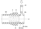
 図28および図29は、押さえ管本体30の変形例である押さえ管本体30Cを示す断面図である。押さえ管本体30Cは、中心軸線O1に垂直な方向から締付部材32を内部空間Sに挿入可能な貫通孔30hを有する。図29に示すように、内部空間Sに挿入された締付部材32は、第一支持面301および第三支持面303によって支持される。
(Modification 9)
28 and 29 are sectional views showing a holding tube main body 30C, which is a modification of the holding tube main body 30. FIG. The hold-down tube main body 30C has a through hole 30h through which the tightening member 32 can be inserted into the internal space S from a direction perpendicular to the central axis O1. As shown in FIG. 29, the tightening member 32 inserted into the internal space S is supported by the first support surface 301 and the third support surface 303. As shown in FIG.
(変形例10)
 図30は、押さえ管3の変形例である押さえ管3Hを示す断面図である。押さえ管3Hは、筒状に形成された押さえ管本体30Hと、突没ウイング31と、締付部材32と、固定部材39と、を有する。押さえ管本体30Hは、第一実施形態の押さえ管本体30と比較して、第一支持面301を備えていない点を除いて同様である。
(Modification 10)
FIG. 30 is a cross-sectional view showing a holding tube 3H that is a modification of the holding tube 3. As shown in FIG. The hold-down tube 3H has a hold-down tube body 30H formed in a cylindrical shape, a protruding wing 31, a tightening member 32, and a fixing member 39. As shown in FIG. The hold down tube main body 30H is the same as the hold down tube main body 30 of the first embodiment except that the first support surface 301 is not provided.
 固定部材39は、金属により円筒状に形成されている。固定部材39は、押さえ管本体30Hの内部空間Sに挿入されて締付部材32を基端側から固定する。押さえ管本体30Hと固定部材39とは、例えばネジやタケノコ圧入などにより固定される。 The fixing member 39 is formed of metal in a cylindrical shape. The fixing member 39 is inserted into the internal space S of the holding tube main body 30H and fixes the tightening member 32 from the proximal end side. The holding tube main body 30H and the fixing member 39 are fixed by, for example, a screw or a bamboo shoot.
(第三実施形態)
 本発明の第三実施形態について、図31から図40を参照して説明する。以降の説明において、既に説明したものと共通する構成については、同一の符号を付して重複する説明を省略する。
(Third embodiment)
A third embodiment of the present invention will be described with reference to FIGS. 31 to 40. FIG. In the following description, the same reference numerals are given to the same configurations as those already described, and redundant descriptions will be omitted.
[クリップユニット1K]
 図31は、本実施形態に係るクリップユニット1Kの斜視図である。図32は、クリップユニット1Kの側面図である。クリップユニット(内視鏡用処置具)1Kは、第一実施形態のクリップユニット1と同様に、クリップ導入装置200に装填して使用される。クリップユニット1Kは、クリップ2Kと、押さえ管3Kと、連結部材4Kと、弾性部材6と、を備える。
[Clip unit 1K]
FIG. 31 is a perspective view of a clip unit 1K according to this embodiment. FIG. 32 is a side view of the clip unit 1K. A clip unit (treatment instrument for an endoscope) 1K is used by loading it into a clip introduction device 200, like the clip unit 1 of the first embodiment. The clip unit 1K includes a clip 2K, a pressing tube 3K, a connecting member 4K, and an elastic member 6.
 クリップ2Kは、第一実施形態のクリップ2と同様に金属製板材を中央部で折り曲げて形成されている。クリップ2Kは、開閉可能な一対のアーム21Kと、一対のアーム21Kを接続する連結部22Kと、を有する。 The clip 2K is formed by bending a metal plate material at the center like the clip 2 of the first embodiment. The clip 2K has a pair of arms 21K that can be opened and closed, and a connecting portion 22K that connects the pair of arms 21K.
 図33は、一対のアーム21Kの斜視図である。
 一対のアーム21Kは、第一アーム211Kと第二アーム212Kとを有する。第一アーム211Kと第二アーム212Kとは、クリップユニット1の長手方向における中心軸線O1に対して対称に配置される。
FIG. 33 is a perspective view of a pair of arms 21K.
The pair of arms 21K has a first arm 211K and a second arm 212K. The first arm 211K and the second arm 212K are arranged symmetrically with respect to the central axis O1 in the longitudinal direction of the clip unit 1 .
 第一アーム211Kは、先端側から基端側に向かって組織把持部251と、平板状の把持部261と、摺動部271と、を有する。第二アーム212Kは、先端側から基端側に向かって組織把持部252と、平板状の把持部262と、摺動部272と、を有する。 The first arm 211K has a tissue grasping portion 251, a flat plate-like grasping portion 261, and a sliding portion 271 from the distal side to the proximal side. The second arm 212K has a tissue grasping portion 252, a flat plate-like grasping portion 262, and a sliding portion 272 from the distal side to the proximal side.
 組織把持部251は、第一アーム211Kの先端を内側に向かって折り曲げられて形成されている。組織把持部252は、第二アーム212Kの先端を内側に向かって折り曲げられて形成されている。図32に示すように、組織把持部251と組織把持部252とは、中心軸線O1に対して非対称な形状に形成されている。そのため、使用者は、一対のアーム21Kを連結部材4Kに取り付ける際に、連結部材4Kに対して一対のアーム21Kを取り付ける向きを把握しやすい。 The tissue gripping portion 251 is formed by bending the tip of the first arm 211K inward. The tissue grasping portion 252 is formed by bending the tip of the second arm 212K inward. As shown in FIG. 32, the tissue gripping portion 251 and the tissue gripping portion 252 are formed in an asymmetrical shape with respect to the central axis O1. Therefore, when attaching the pair of arms 21K to the connecting member 4K, the user can easily grasp the direction in which the pair of arms 21K are attached to the connecting member 4K.
 図34は、図33の領域R1の拡大図である。
 摺動部271,272は、一対のアーム21Kが押さえ管3Kに引き込まれる際に弾性変形する部分である。摺動部271,272は、開閉方向Pにおける外側の外周面271b,272bにおいて、長手方向に沿って端部が面打ちされた面打ち部271c,272cを有する。摺動部271,272は、面打ち部271c,272cを有するため、一対のアーム21Kが押さえ管3Kに引き込まれる際、押さえ管3Kの先端開口3Kaに引っ掛かりにくい。
FIG. 34 is an enlarged view of region R1 in FIG.
The sliding portions 271 and 272 are portions that are elastically deformed when the pair of arms 21K are pulled into the pressing tube 3K. The sliding portions 271 and 272 have chamfered portions 271c and 272c whose ends are chamfered along the longitudinal direction on outer peripheral surfaces 271b and 272b on the outer side in the opening/closing direction P. As shown in FIG. Since the sliding portions 271 and 272 have the chamfered portions 271c and 272c, when the pair of arms 21K are pulled into the pressing tube 3K, they are less likely to get caught in the tip opening 3Ka of the pressing tube 3K.
 図35は、押さえ管3Kに一部が収容された一対のアーム21Kを示す図である。
 把持部261と摺動部271との連結部分には、開閉方向Pに直交する方向にストッパ281が形成されている。把持部262と摺動部272との連結部分には、開閉方向Pに直交する方向にストッパ282が形成されている。図35に示すように、一対のアーム21Kが押さえ管3Kに引き込まれると、ストッパ281,282が押さえ管3Kの先端開口3Kaと係合する。すなわち、ストッパ281,282は、一対のアーム21Kが押さえ管3Kに引き込まれる位置を規制する。
FIG. 35 is a diagram showing a pair of arms 21K partly housed in the pressing tube 3K.
A stopper 281 is formed in a direction orthogonal to the opening/closing direction P at the connecting portion between the grip portion 261 and the sliding portion 271 . A stopper 282 is formed in a direction orthogonal to the opening/closing direction P at the connecting portion between the grip portion 262 and the sliding portion 272 . As shown in FIG. 35, when the pair of arms 21K is pulled into the holding tube 3K, the stoppers 281 and 282 engage with the tip opening 3Ka of the holding tube 3K. That is, the stoppers 281 and 282 regulate the position at which the pair of arms 21K is pulled into the pressing tube 3K.
 摺動部271,272には、図32に示すように、弾性部材6の先端部6aの先端側を支持する第一支持部29aと、先端部6aの基端側を支持する第二支持部29bと、が設けられている。第一支持部29aと第二支持部29bは、弾性部材6の先端部6aを挟み込んでいる。そのため、一対のアーム21Kに対する弾性部材6の伸縮動作が安定する。 As shown in FIG. 32, the sliding portions 271 and 272 include a first support portion 29a that supports the distal end side of the distal end portion 6a of the elastic member 6, and a second support portion that supports the proximal end side of the distal end portion 6a. 29b and are provided. The first support portion 29a and the second support portion 29b sandwich the distal end portion 6a of the elastic member 6 therebetween. Therefore, the expansion/contraction operation of the elastic member 6 with respect to the pair of arms 21K is stabilized.
 図36は、一対のアーム21Kの基端部の側面図である。
 第一アーム211Kの基端側および第二アーム212Kの基端側には、中心軸線O1に垂直な方向に突出する係合部24が形成されている。係合部24の先端側は鋭角な斜面、係合部24の連結部22側は鈍角な斜面に形成されている。係合部24は、押さえ管3Kの内部領域Sに収容される収容領域Tに設けられている。収容領域Tは、一対のアーム21Kが開閉したときに、常に押さえ管3Kの内部領域Sに収容されている領域である。
FIG. 36 is a side view of the base ends of the pair of arms 21K.
Engagement portions 24 projecting in a direction perpendicular to the central axis O1 are formed on the base end side of the first arm 211K and the base end side of the second arm 212K. The front end side of the engaging portion 24 is formed to have an acute slope, and the connecting portion 22 side of the engaging portion 24 is formed to have an obtuse slope. The engaging portion 24 is provided in a housing area T that is housed in the inner area S of the pressing tube 3K. The housing region T is a region that is always housed in the inner region S of the pressing tube 3K when the pair of arms 21K are opened and closed.
 第一アーム211Kと第二アーム212Kとは、基端側において連結部22Kにより連結されており、先端側に向かって開閉自在に設けられている。連結部22Kは、折り曲げられてU字状に形成されており、連結部材4Kと連結される The first arm 211K and the second arm 212K are connected by a connecting portion 22K on the base end side, and are provided so as to be openable and closable toward the tip end side. The connecting portion 22K is bent to have a U shape and is connected to the connecting member 4K.
 連結部22Kの長手軸に沿う軸線22aは、図36に示すように、中心軸線O1から径方向Rの外側に位置している。そのため、フック状に形成されたフック41fに引っ掛けやすい。 As shown in FIG. 36, the axis 22a along the longitudinal axis of the connecting portion 22K is positioned radially outward from the central axis O1. Therefore, it is easy to hook on the hook 41f formed in the shape of a hook.
 押さえ管3Kは、押さえパイプ5と、押さえ管3と、を有する。押さえパイプ5は、金属製の円筒部材部材である。押さえパイプ5は、押さえ管3の先端部に圧入されている。押さえ管3Kと押さえパイプ5とは、熱溶着、接着またはねじ止めにより連結されていてもよい。 The holding pipe 3K has a holding pipe 5 and a holding pipe 3. The holding pipe 5 is a metal cylindrical member. The holding pipe 5 is press-fitted into the tip of the holding tube 3 . The holding tube 3K and the holding pipe 5 may be connected by heat welding, adhesion, or screwing.
 押さえパイプ5の先端側に形成された先端開口3Kaは、一対のアーム21Kの摺動部271,272と係合する。先端開口3Kaは、例えば磁気バレル処理などの表面処理によりバリが除去されており、摺動部271,272に引っ掛かりにくい。先端開口3Kaは、例えば窒化処理などの表面硬度を高める表面処理が施されていてもよい。先端開口3Kaの表面硬度が高くなることにより、先端開口3Kaは摺動部271,272に引っ掛かりにくくなる。 A tip opening 3Ka formed on the tip side of the holding pipe 5 engages with the sliding portions 271 and 272 of the pair of arms 21K. The tip opening 3Ka is freed from burrs by surface treatment such as magnetic barrel treatment, and is less likely to be caught by the sliding portions 271 and 272. As shown in FIG. The tip opening 3Ka may be subjected to a surface treatment such as nitriding to increase the surface hardness. By increasing the surface hardness of the tip opening 3Ka, the tip opening 3Ka is less likely to be caught by the sliding portions 271 and 272. FIG.
 連結部材4Kは、クリップ2Kの連結部22Kに連結される。また、連結部材4Kは、シース220内を挿通する矢尻フック部231に連結される。連結部材4Kは、押さえ管3Kの内部空間に挿入される挿入部41Kと、挿入部41Kの基端に設けられた連結部42と、を備える。 The connecting member 4K is connected to the connecting portion 22K of the clip 2K. In addition, the connecting member 4K is connected to an arrowhead hook portion 231 passing through the sheath 220 . The connecting member 4K includes an inserting portion 41K inserted into the inner space of the pressing tube 3K, and a connecting portion 42 provided at the proximal end of the inserting portion 41K.
 挿入部41Kは、先端部にフック41fと、マーキング41pと、ストッパ41rと、を有する。マーキング41pは、径方向Rの外側に突出する凸部であり、周方向Cにおいて一部分のみに形成されている。そのため、使用者は、一対のアーム21Kを連結部材4Kに取り付ける際に、連結部材4Kに対して一対のアーム21Kを取り付ける向きを把握しやすい。 The insertion portion 41K has a hook 41f, a marking 41p, and a stopper 41r at its tip. The marking 41p is a convex portion that protrudes outward in the radial direction R and is formed only partially in the circumferential direction C. As shown in FIG. Therefore, when attaching the pair of arms 21K to the connecting member 4K, the user can easily grasp the direction in which the pair of arms 21K are attached to the connecting member 4K.
 ストッパ41rは、径方向Rの外側に突出する凸部であり、周方向Cに沿ってリング状に形成されている。ストッパ41rは、押さえ管3Kの基端と係合する。すなわち、ストッパ41rは、連結部材4Kが押さえ管3Kに引き込まれる位置を規制する。 The stopper 41r is a convex portion that protrudes outward in the radial direction R and is formed in a ring shape along the circumferential direction C. The stopper 41r engages with the proximal end of the pressing tube 3K. That is, the stopper 41r regulates the position where the connecting member 4K is pulled into the pressing tube 3K.
 弾性部材6は、クリップ2Kを先端側に付勢するバネである。図31に示すように、弾性部材6の基端部6bには、座巻が形成され、連結部材4Kと安定して係合できる。 The elastic member 6 is a spring that biases the clip 2K forward. As shown in FIG. 31, the base end portion 6b of the elastic member 6 is formed with an end turn so that it can be stably engaged with the connecting member 4K.
[クリップユニット1Kの動作および作用]
 次に、クリップユニット1Kの動作および作用について説明する。
[Operation and Action of Clip Unit 1K]
Next, the operation and action of the clip unit 1K will be described.
 図37は、クリップ導入装置200のシース220に装填されたクリップユニット1Kを示す断面図である。図37において、押さえパイプ5、弾性部材6、および連結部材4Kと連結される矢尻フック部231等の記載は省略されている。 37 is a cross-sectional view showing the clip unit 1K loaded in the sheath 220 of the clip introduction device 200. FIG. In FIG. 37, description of the pressing pipe 5, the elastic member 6, the arrowhead hook portion 231 connected with the connecting member 4K, and the like is omitted.
 図38は、突没ウイング31の断面図である。
 突没ウイング31は、シース220の内周面により押し付けられて没状態となっている。突没ウイング31は、先端側から基端側に向かって第一斜面31a、第二斜面32b、および第三斜面31cを有する。第一斜面31a、第二斜面32b、および第三斜面31cは、中心軸線O1に対する法線の向きが異なる。そのため、突没ウイング31がシース220に引っ掛かりにくい。
38 is a sectional view of the projecting wing 31. FIG.
The projecting wing 31 is pressed by the inner peripheral surface of the sheath 220 and is in a recessed state. The projecting wing 31 has a first slope 31a, a second slope 32b, and a third slope 31c from the distal end side to the proximal end side. The first slope 31a, the second slope 32b, and the third slope 31c have different normal directions with respect to the central axis O1. Therefore, the retractable wing 31 is less likely to get caught on the sheath 220 .
 没状態である突没ウイング31の内周面は、図37に示すように、連結部材4Kの挿入部41Kを挟み込む。突没ウイング31は、連結部材4Kの先端側から基端側への移動を規制する。その結果、押さえ管3Kと連結部材4Kとの相対的に位置ずれを抑制できる。 As shown in FIG. 37, the inner peripheral surface of the retracted wing 31 sandwiches the insertion portion 41K of the connecting member 4K. The projecting wing 31 restricts movement of the connecting member 4K from the distal end side to the proximal end side. As a result, it is possible to suppress relative displacement between the pressing tube 3K and the connecting member 4K.
 図39は、突没ウイング31の変形例である突没ウイング31Bを示す断面図である。
 突没ウイング31Bは、内周面の基端側において径方向Rの内側に突出するフック31fを有する。没状態である突没ウイング31Bは、連結部材4Kの先端側から基端側への移動をより確実に規制できる。
FIG. 39 is a sectional view showing a retractable wing 31B that is a modified example of the retractable wing 31. FIG.
The protruding wing 31B has a hook 31f protruding inward in the radial direction R on the base end side of the inner peripheral surface. The retracted wing 31B can more reliably restrict the movement of the connecting member 4K from the distal end side to the proximal end side.
 図40は、シース220から先端側に突出させたクリップユニット1Kを示す側面図である。使用者は、スライダ242を操作部本体241に沿って前進させることで、矢尻フック部231を前進させる。使用者は、突没ウイング31がシース220から出るまで、クリップユニット1Kを前進させる。突没ウイング31は、先端側がシース220から出ることにより、没状態から基本姿勢である突状態に戻る。 FIG. 40 is a side view showing the clip unit 1K protruding from the sheath 220 toward the tip side. The user advances the arrowhead hook portion 231 by advancing the slider 242 along the operation portion main body 241 . The user advances the clip unit 1K until the retractable wings 31 come out of the sheath 220. - 特許庁When the tip side of the retractable wing 31 comes out of the sheath 220, it returns from the retracted state to the projected state, which is the basic posture.
 シース220の先端側に内周面には、他の部分より内径が小さい縮径部220sが設けられている。ワイヤ232の先端側には、他の部分より外径が大きい拡径部232sが設けられている。拡径部232sは、縮径部220sを通過可能であるが、通過時には縮径部220sの内周面に接触する。そのため、拡径部232sが縮径部220sを通過するスライダ242の進退操作には、通常の進退操作より大きな力が必要である。使用者は、スライダ242の進退操作に通常よりも高い負荷を感じることにより、拡径部232sが縮径部220sを通過していることを把握できる。縮径部220sおよび拡径部232sを適切に位置に設けることにより、使用者がワイヤ232を意図しない領域まで移動させてしまうことを抑制できる。 A reduced-diameter portion 220s having a smaller inner diameter than other portions is provided on the inner peripheral surface of the sheath 220 on the distal end side. An enlarged diameter portion 232s having a larger outer diameter than other portions is provided on the tip side of the wire 232 . The enlarged diameter portion 232s can pass through the reduced diameter portion 220s, but contacts the inner peripheral surface of the reduced diameter portion 220s during passage. Therefore, the advancing/retreating operation of the slider 242 in which the diameter-enlarged portion 232s passes through the diameter-reducing portion 220s requires a larger force than a normal advancing/retreating operation. The user can grasp that the expanded diameter portion 232s is passing through the reduced diameter portion 220s by feeling a load higher than usual when the slider 242 is moved back and forth. By providing the diameter-reduced portion 220s and the diameter-enlarged portion 232s at appropriate positions, it is possible to prevent the user from moving the wire 232 to an unintended area.
 本実施形態に係るクリップユニット1Kによれば、リング状の締付部材32が押さえ管3Kの内部領域Sに設けられているため、掴み直し可能なクリップ2Kを押さえ管3Kにより確実に閉状態にロックできる。 According to the clip unit 1K according to this embodiment, since the ring-shaped tightening member 32 is provided in the inner region S of the holding tube 3K, the clip 2K that can be regrasped is securely closed by the holding tube 3K. can be locked.
 以上、本発明の第三実施形態について図面を参照して詳述したが、具体的な構成はこの実施形態に限られるものではなく、本発明の要旨を逸脱しない範囲の設計変更等も含まれる。また、上述の実施形態および変形例において示した構成要素は適宜に組み合わせて構成することが可能である。 As described above, the third embodiment of the present invention has been described in detail with reference to the drawings, but the specific configuration is not limited to this embodiment, and design changes and the like are included within the scope of the present invention. . Also, the constituent elements shown in the above-described embodiment and modifications can be combined as appropriate.
(変形例11)
 図41から図43は、押さえパイプ5の変形例である押さえパイプ5B、押さえパイプ5C、および押さえパイプ5Dを示す図である。押さえパイプ5B、押さえパイプ5C、および押さえパイプ5Dは、外周面において周方向Cに沿う溝5gを有する。押さえパイプ5B、押さえパイプ5C、および押さえパイプ5Dは、有する溝5gの数が異なる。クリップユニット1Kの種類ごとに外見の異なる押さえパイプを使い別けることで、使用者はクリップユニット1Kの種類を把握しやすい。
(Modification 11)
41 to 43 are diagrams showing a holding pipe 5B, a holding pipe 5C, and a holding pipe 5D, which are modifications of the holding pipe 5. FIG. The pressing pipe 5B, the pressing pipe 5C, and the pressing pipe 5D have grooves 5g extending in the circumferential direction C on their outer peripheral surfaces. The holding pipe 5B, the holding pipe 5C, and the holding pipe 5D have different numbers of grooves 5g. A user can easily recognize the type of the clip unit 1K by using different holding pipes with different appearances for each type of the clip unit 1K.
 本発明は、クリップユニット等の内視鏡用処置具に適用することができる。 The present invention can be applied to endoscopic treatment tools such as clip units.
100 クリップ装置
200 クリップ導入装置
1,1K クリップユニット(内視鏡用処置具)
2,2K クリップ
21,21K 一対のアーム(複数のアーム)
24,24K 係合部
3 押さえ管
31 突没ウイング
30s 支持面
33 スナップフィット部
4,4K 連結部材
T 収容領域
S 内部領域
100 clip device 200 clip introduction device 1, 1K clip unit (treatment tool for endoscope)
2, 2K Clips 21, 21K Pair of arms (plurality of arms)
24, 24K Engagement portion 3 Pressing tube 31 Protruding wing 30s Support surface 33 Snap fit portion 4, 4K Connecting member T Accommodation region S Internal region

Claims (11)

  1.  先端側が開閉自在である複数のアームを有するクリップと、
     前記クリップの基端側の少なくとも一部が挿入される筒状の押さえ管と、
     を備え、
     前記押さえ管は、前記押さえ管の内部領域に設けられた締付部材と、径方向外側に対して突没可能な突没ウイングと、を有し、
     前記締付部材は、前記突没ウイングよりも基端側に設けられ
     前記クリップは、前記内部領域に収容される収容領域において係合部を有し、
     基端側へ移動した前記係合部が前記締付部材と係合することにより、前記クリップは前記押さえ管に対する先端側への移動が規制される、
     内視鏡用処置具。
    a clip having a plurality of arms whose distal ends can be freely opened and closed;
    a cylindrical holding tube into which at least a portion of the proximal side of the clip is inserted;
    with
    The hold-down tube has a tightening member provided in an inner region of the hold-down tube, and a projecting wing capable of projecting outward in a radial direction,
    the tightening member is provided closer to the proximal end than the protruding wing, and the clip has an engaging portion in a housing area that is housed in the internal area;
    When the engaging portion that has moved to the proximal side engages with the tightening member, the clip is restricted from moving to the distal side with respect to the holding tube.
    An endoscope treatment tool.
  2.  前記締付部材は、リング状に形成されている、
     請求項1に記載の内視鏡用処置具。
    The tightening member is formed in a ring shape,
    The endoscopic treatment tool according to claim 1.
  3.  前記締付部材は、前記押さえ管の他の部分よりも硬い材料で形成されている、
     請求項1に記載の内視鏡用処置具。
    The tightening member is made of a material harder than other parts of the holding tube,
    The endoscopic treatment tool according to claim 1.
  4.  前記締付部材は金属で形成されており、
     前記押さえ管の他の部分は、樹脂で形成されている、
     請求項3に記載の内視鏡用処置具。
    The tightening member is made of metal,
    The other portion of the holding tube is made of resin,
    The endoscope treatment tool according to claim 3.
  5.  前記押さえ管は、前記締付部材を基端側から支持する支持面を有する、
     請求項1に記載の内視鏡用処置具。
    The holding tube has a support surface that supports the tightening member from the proximal end side,
    The endoscopic treatment tool according to claim 1.
  6.  前記押さえ管は、前記締付部材を先端側から支持する支持面を有する、
     請求項5に記載の内視鏡用処置具。
    The holding tube has a support surface that supports the tightening member from the tip side,
    The endoscopic treatment tool according to claim 5.
  7.  前記締付部材は、前記押さえ管に設けられたスナップフィット部により取り付けられている、
     請求項1に記載の内視鏡用処置具。
    The tightening member is attached by a snap-fit portion provided on the holding tube,
    The endoscopic treatment tool according to claim 1.
  8.  前記締付部材は、インサート成形により前記押さえ管に取り付けられる
     請求項1に記載の内視鏡用処置具。
    The endoscopic treatment instrument according to claim 1, wherein the tightening member is attached to the holding tube by insert molding.
  9.  前記締付部材は、支持部材に連結されることにより支持されており、
     前記押さえ管は、前記支持部材を基端側から支持する、
     請求項1に記載の内視鏡用処置具。
    The tightening member is supported by being connected to a support member,
    The holding tube supports the support member from the proximal side,
    The endoscopic treatment tool according to claim 1.
  10.  前記締付部材は、前記押さえ管に挿入される先端部と、前記押さえ管から基端側に露出する基端部と、を有し、
     前記先端部は、内周面に前記係合部と係合するリング部が形成されている。
     請求項1に記載の内視鏡用処置具。
    The tightening member has a distal end portion inserted into the holding tube and a proximal end portion exposed from the holding tube to the proximal end side,
    A ring portion that engages with the engaging portion is formed on the inner peripheral surface of the tip portion.
    The endoscopic treatment tool according to claim 1.
  11.  請求項1から請求項10のいずれか一項に記載の内視鏡用処置具と、
     クリップ導入装置と、
     を備えた。
     クリップ装置。
    The endoscopic treatment tool according to any one of claims 1 to 10;
    a clip introducer;
    provided.
    clip device.
PCT/JP2021/009575 2021-01-26 2021-03-10 Endoscopic treatment tool and clip device WO2022190272A1 (en)

Priority Applications (9)

Application Number Priority Date Filing Date Title
CN202180095329.9A CN116963678A (en) 2021-03-10 2021-03-10 Treatment tool for endoscope and jig device
PCT/JP2021/009575 WO2022190272A1 (en) 2021-03-10 2021-03-10 Endoscopic treatment tool and clip device
JP2023504974A JPWO2022190272A1 (en) 2021-03-10 2021-03-10
DE112021006999.3T DE112021006999T5 (en) 2021-03-10 2021-03-10 ENDOSCOPE TREATMENT TOOL AND CLIP DEVICE
US17/584,741 US11944321B2 (en) 2021-01-26 2022-01-26 Endoscopic treatment device
CN202210189581.2A CN115068013A (en) 2021-03-10 2022-02-28 Endoscopic treatment instrument and jig device
CN202220412926.1U CN217471990U (en) 2021-03-10 2022-02-28 Endoscopic treatment instrument and jig device
US18/462,880 US20230414225A1 (en) 2021-03-10 2023-09-07 Endoscopic treatment tool and clip device
US18/594,295 US20240206883A1 (en) 2021-01-26 2024-03-04 Endoscopic treatment device

Applications Claiming Priority (1)

Application Number Priority Date Filing Date Title
PCT/JP2021/009575 WO2022190272A1 (en) 2021-03-10 2021-03-10 Endoscopic treatment tool and clip device

Related Child Applications (1)

Application Number Title Priority Date Filing Date
US18/462,880 Continuation US20230414225A1 (en) 2021-03-10 2023-09-07 Endoscopic treatment tool and clip device

Publications (1)

Publication Number Publication Date
WO2022190272A1 true WO2022190272A1 (en) 2022-09-15

Family

ID=83227621

Family Applications (1)

Application Number Title Priority Date Filing Date
PCT/JP2021/009575 WO2022190272A1 (en) 2021-01-26 2021-03-10 Endoscopic treatment tool and clip device

Country Status (5)

Country Link
US (1) US20230414225A1 (en)
JP (1) JPWO2022190272A1 (en)
CN (3) CN116963678A (en)
DE (1) DE112021006999T5 (en)
WO (1) WO2022190272A1 (en)

Citations (2)

* Cited by examiner, † Cited by third party
Publication number Priority date Publication date Assignee Title
JP2009022776A (en) * 2008-09-16 2009-02-05 Olympus Corp Ligating device of biological tissue
WO2020095428A1 (en) * 2018-11-09 2020-05-14 オリンパス株式会社 Clip unit and endoscope clip

Patent Citations (2)

* Cited by examiner, † Cited by third party
Publication number Priority date Publication date Assignee Title
JP2009022776A (en) * 2008-09-16 2009-02-05 Olympus Corp Ligating device of biological tissue
WO2020095428A1 (en) * 2018-11-09 2020-05-14 オリンパス株式会社 Clip unit and endoscope clip

Also Published As

Publication number Publication date
CN116963678A (en) 2023-10-27
DE112021006999T5 (en) 2023-12-07
JPWO2022190272A1 (en) 2022-09-15
CN115068013A (en) 2022-09-20
US20230414225A1 (en) 2023-12-28
CN217471990U (en) 2022-09-23

Similar Documents

Publication Publication Date Title
JP5343113B2 (en) Clip unit and ligating apparatus using the same
JP5588711B2 (en) Ligation device
JP2006158668A (en) Treatment instrument for endoscope
JP5427858B2 (en) Ligating device and endoscope system
US5501692A (en) Laparoscopic suture snare
JP5427857B2 (en) Clip unit, ligating apparatus using the same, and manufacturing method of clip unit
JP5750619B2 (en) Clip unit
JP6663992B2 (en) Endoscope treatment tool
WO2004017839A1 (en) Ligating device for biological tissue
WO2006068242A1 (en) Ligation device
JP4427070B2 (en) Clip case
JP6084347B1 (en) Endoscopic treatment tool
EP1796551A2 (en) Suturing instrument
US20210251633A1 (en) Endoscope clip and operation method for clip arm
JP7009613B2 (en) Reloadable rotary clip
WO2015019781A1 (en) Suture device
JP2004073646A (en) Ligature apparatus for viable tissue
JP4472719B2 (en) Biological tissue clip device
WO2022190272A1 (en) Endoscopic treatment tool and clip device
JP2007196012A (en) Clip device for living body tissue
JP7286743B2 (en) Clip delivery device and clip unit
JP4755234B2 (en) Biological tissue ligation device
WO2013038779A1 (en) Medical treatment instrument
JP7474890B2 (en) Clip Systems and Applicators
US20240260969A1 (en) Cartridge and cartridge system

Legal Events

Date Code Title Description
121 Ep: the epo has been informed by wipo that ep was designated in this application

Ref document number: 21930128

Country of ref document: EP

Kind code of ref document: A1

WWE Wipo information: entry into national phase

Ref document number: 202180095329.9

Country of ref document: CN

WWE Wipo information: entry into national phase

Ref document number: 2023504974

Country of ref document: JP

WWE Wipo information: entry into national phase

Ref document number: 202347062159

Country of ref document: IN

WWE Wipo information: entry into national phase

Ref document number: 112021006999

Country of ref document: DE

122 Ep: pct application non-entry in european phase

Ref document number: 21930128

Country of ref document: EP

Kind code of ref document: A1