WO2022190163A1 - 電動機 - Google Patents
電動機 Download PDFInfo
- Publication number
- WO2022190163A1 WO2022190163A1 PCT/JP2021/008941 JP2021008941W WO2022190163A1 WO 2022190163 A1 WO2022190163 A1 WO 2022190163A1 JP 2021008941 W JP2021008941 W JP 2021008941W WO 2022190163 A1 WO2022190163 A1 WO 2022190163A1
- Authority
- WO
- WIPO (PCT)
- Prior art keywords
- outside air
- guide
- electric motor
- air
- bracket
- Prior art date
- Legal status (The legal status is an assumption and is not a legal conclusion. Google has not performed a legal analysis and makes no representation as to the accuracy of the status listed.)
- Ceased
Links
Images








Classifications
-
- H—ELECTRICITY
- H02—GENERATION; CONVERSION OR DISTRIBUTION OF ELECTRIC POWER
- H02K—DYNAMO-ELECTRIC MACHINES
- H02K9/00—Arrangements for cooling or ventilating
- H02K9/02—Arrangements for cooling or ventilating by ambient air flowing through the machine
- H02K9/04—Arrangements for cooling or ventilating by ambient air flowing through the machine having means for generating a flow of cooling medium
- H02K9/06—Arrangements for cooling or ventilating by ambient air flowing through the machine having means for generating a flow of cooling medium with fans or impellers driven by the machine shaft
-
- H—ELECTRICITY
- H02—GENERATION; CONVERSION OR DISTRIBUTION OF ELECTRIC POWER
- H02K—DYNAMO-ELECTRIC MACHINES
- H02K9/00—Arrangements for cooling or ventilating
- H02K9/14—Arrangements for cooling or ventilating wherein gaseous cooling medium circulates between the machine casing and a surrounding mantle
- H02K9/18—Arrangements for cooling or ventilating wherein gaseous cooling medium circulates between the machine casing and a surrounding mantle wherein the external part of the closed circuit comprises a heat exchanger structurally associated with the machine casing
Definitions
- This disclosure relates to electric motors.
- the electric motor includes a shaft, a rotor that is attached to the shaft and rotates together, a stator facing the rotor with a gap in the radial direction, and bearings that rotatably support the shaft.
- the temperature of the stator and rotor which are components of the electric motor, rises.
- a rise in the temperature of components of an electric motor for example, accelerates insulation deterioration of stator coils and rotor conductors, accelerates deterioration of grease lubricating bearings, etc., and thus may affect the service life of the electric motor.
- outside air which is the air outside the electric motor
- inside air which is the air inside the electric motor
- the stator and rotor are cooled. Since the temperature of the inside air is higher than that of the outside air, the cooling performance of the inside air is lower than that of the outside air.
- a ventilation passage is formed in the stator and the rotor.
- a heat exchanger is provided having air passages communicating therein.
- the stator and rotor are cooled by allowing the outside air to flow through the ventilation passages formed in the stator and the inside air to flow through the ventilation passages formed in the rotor.
- the temperature rise of the inside air is suppressed by causing the inside air to flow through the ventilation passages of the heat exchanger provided with fins along the entire circumference of the outer peripheral surface.
- the present disclosure has been made in view of the circumstances described above, and aims to provide an electric motor with high efficiency and cooling performance.
- the electric motor of the present disclosure includes a shaft, a rotor, a stator, a first bracket, a second bracket, a bypass forming portion, a first guide, a second guide, Prepare.
- the shaft is rotatably supported around the rotation axis.
- the rotor is positioned radially outside the shaft and rotates together with the shaft.
- the stator faces the rotor with a gap in the radial direction, and has an outside air ventilation passage, which is a through hole opened at both ends in the extending direction of the rotating shaft.
- the first bracket is formed with an inflow hole through which outside air is introduced.
- the second bracket faces the first bracket in the extending direction of the rotating shaft with the rotor and the stator interposed therebetween.
- the bypass forming portion forms an internal air bypass through which internal air flows radially outward of the stator.
- the first guide includes a first tube positioned between the first bracket and the stator, and a plurality of tubular first guides each extending from the outer peripheral surface of the first tube and communicating between the internal air bypass and the internal space of the first tube. of the first partition.
- the first guide transfers heat transferred from the inside air passing through the interiors of the plurality of first partitions to the outside air flowing in through the inflow holes, and guides the outside air to the outside air ventilation passage.
- the second guide includes a second cylinder positioned between the second bracket and the stator, and a cylindrical second partition wall extending from the outer peripheral surface of the second cylinder and communicating between the inside air bypass and the internal space of the second cylinder. have a part. The second guide transfers heat transferred from the inside air passing through the inside of the second partition to the outside air passing through the outside air ventilation passage, and guides the outside air to the outside.
- the electric motor of the present disclosure includes a first guide having a plurality of tubular first partitions that communicate between the internal air bypass and the internal space, and a second tubular partition that communicates the internal air bypass with the internal space. 2 guides;
- the first guide transfers heat transferred from the inside air passing inside the plurality of first partitions to the outside, and the second guide transfers heat transferred from the inside air passing inside the second partitions to the outside.
- the temperature rise of the inside air of the electric motor can be suppressed. As a result, an electric motor with high efficiency and cooling performance is obtained.
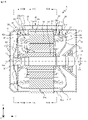
- FIG. 2 is a diagram showing the flow of outside air and inside air in the electric motor according to Embodiment 1; Sectional view of the electric motor according to Embodiment 2 Sectional view of the electric motor according to Embodiment 2 Cross-sectional view taken along line XI-XI in FIG. 9 of the electric motor according to Embodiment 2 Perspective view of the first guide according to the second embodiment Perspective view of the second guide according to the second embodiment
- FIG. 6 is a diagram showing the flow of outside air and inside air in the electric motor according to Embodiment 2; Sectional view of the electric motor according to Embodiment 3 Cross-sectional view taken along line XVI-XVI in FIG.
- FIG. 10 is a diagram showing the flow of outside air and inside air in the electric motor according to Embodiment 3; Sectional view of the first modification of the electric motor according to the embodiment The top view of the 2nd modification of the electric motor which concerns on embodiment
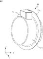
- Electric motor 1 according to Embodiment 1 will be described using a fully enclosed electric motor for driving a railroad vehicle.
- the electric motor 1 shown in FIG. 1 is installed under the floor of a railway vehicle.
- the electric motor 1 cools the components of the electric motor 1 by the flow of outside air, which is the air outside the electric motor 1 , and internal air, which is the air inside the electric motor 1 .
- the Z-axis direction indicates the vertical direction.
- the Y-axis direction indicates the width direction of the railcar.
- the X-axis direction indicates the traveling direction of the railway vehicle. In other words, the railcar travels in the positive direction of the X-axis or the negative direction of the X-axis.
- the X-, Y-, and Z-axes are orthogonal to each other.
- the electric motor 1 includes a shaft 11 rotatably supported around a rotation axis AX indicated by a dashed line in FIG.
- a stator 13 facing the element 12 with a gap in the radial direction, and bearings 14 and 15 rotatably supporting the shaft 11 are provided.
- the electric motor 1 further includes a frame 16 that houses the rotor 12, the stator 13, and the bearings 14 and 15 with the shaft 11 inserted therethrough; 2 brackets 18 and a bypass forming portion 19 forming an internal air bypass 19a.
- the electric motor 1 further includes a first cylinder positioned between the first bracket 17 and the stator 13, and a plurality of tubular first partition walls communicating between the internal air bypass 19a and the internal space 24 of the first cylinder.
- a first guide 20 having a portion 20a, a second cylinder positioned between the second bracket 18 and the stator 13, and a cylindrical second cylinder that communicates the internal air bypass 19a with the internal space 25 of the second cylinder.
- a second guide 21 having a partition wall portion 21a.
- the electric motor 1 further includes an external fan 22 that is attached to the shaft 11 and rotates to let outside air flow in, and an internal fan 23 that is attached to the shaft 11 and rotates to circulate the inside air.
- Heat is transferred from inside air passing inside the plurality of first partition walls 20a and second partition walls 21a to outside air flowing around the plurality of first partition walls 20a and second partition walls 21a, thereby increasing the temperature of the inside air. decreases. As a result, the cooling performance of the electric motor 1 is improved. Since it is not necessary to increase the air volume by increasing the size of the external fan 22 and the internal fan 23 in order to improve the cooling performance of the electric motor 1, the electric motor 1 is a motor with high efficiency and high cooling performance.
- One end of the shaft 11 near the second bracket 18 is connected to the axle of the railway vehicle via a joint and gears (not shown). Rotation of the shaft 11 provides power to the railway vehicle.
- the rotor 12 includes a rotor core 31 attached to the shaft 11, rotor conductors 32 inserted into slots formed on the outer peripheral surface of the rotor core 31, and the rotor core 31 extending in the extension direction of the rotation axis AX.
- a pair of clamping members 33 clamp and fix.
- the rotor core 31 is formed with rotor ventilation passages 31a that are through holes that open at both ends in the extending direction of the rotation axis AX.
- the rotor ventilation passage 31a penetrates the rotor core 31 in the extending direction of the rotation axis AX, that is, in the Y-axis direction.
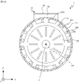
- FIG. 2 which is a cross-sectional view taken along the line II-II in FIG.
- rotor ventilation passages 31a are formed in the circumferential direction.
- illustration of the rotor conductor 32, the sandwiching member 33, and the stator coil 35, which will be described later, is omitted in FIG.
- each holding member 33 is formed with a through hole 33a that communicates with the rotor ventilation passage 31a.
- the through hole 33a penetrates the holding member 33 in the Y-axis direction.
- the inside air flows in order through a through hole 33a formed in one of the pair of holding members 33, a rotor ventilation passage 31a, and a through hole 33a formed in the other of the pair of holding members 33, and the heat generated in the rotor 12 is transmitted to the inside air to cool the rotor 12 .
- the stator 13 has a stator core 34 attached to the inner peripheral surface of the frame 16 and stator coils 35 inserted into slots formed in the stator core 34 .
- the stator core 34 faces the rotor core 31 with a gap in the radial direction.
- An outside air ventilation passage 34 a is formed in the stator core 34 .
- the outside air ventilation path 34a is a through hole that opens at both ends in the extending direction of the rotation axis AX.
- the outside air ventilation passage 34a penetrates the stator core 34 in the Y-axis direction.
- the stator core 34 is provided with a plurality of outside air ventilation passages 34a arranged in the circumferential direction.
- the stator coil 35 is connected to a lead wire 51 drawn from the outside of the electric motor 1 .
- the electric motor 1 is operated by the current flowing through the stator coil 35 via the lead wire 51 .
- the bearing 14 is supported by the frame 16 and rotatably supports the shaft 11 .
- the bearing 15 is supported by the second bracket 18 and rotatably supports the shaft 11 .
- the frame 16 is attached to the underfloor of the railway vehicle by a fixing member (not shown).
- Frame 16 has a tubular shape.
- the frame 16 has a tubular portion 36 and a plate portion 37 that closes one end of the tubular portion 36 and supports the bearing 14 .
- An outflow hole 36a is formed at the end portion of the tubular portion 36 near the second bracket 18 to allow outside air that has passed through the outside air ventilation passage 34a to flow out to the outside.
- the end portion of the tubular portion 36 closer to the second bracket 18 is the portion of the tubular portion 36 closer to the second bracket 18 than the stator 13 .
- FIG. 3 which is a cross-sectional view taken along line III-III in FIG.
- a plurality of outflow holes 36a arranged in the circumferential direction are formed.
- illustration of the rotor conductors 32, the sandwiching members 33, and the stator coils 35 is omitted in FIG.
- Each outflow hole 36a penetrates the cylindrical portion 36 in the radial direction.
- a plurality of first ventilation holes 36b and second ventilation holes 36c are formed in the vertical upper portion of the cylindrical portion 36, which are connected to the inside air bypass 19a.
- FIG. 4 which is a cross-sectional view taken along line IV-IV in FIG.
- Each end face ventilation hole 37a penetrates the plate portion 37 in the Y-axis direction.
- the plate portion 37 is formed with six end face ventilation holes 37a.
- the first bracket 17 is formed with an inflow hole 17a through which outside air flows.
- an inflow hole 17a is formed that penetrates the first bracket 17 in the Y-axis direction.
- the first bracket 17 is attached to one end of the frame 16 , specifically to one end of the cylindrical portion 36 .
- the method of attaching the first bracket 17 to one end of the cylindrical portion 36 is any method that enables the attachment to be strong enough to prevent the relative position from changing due to vibrations that occur when the railroad vehicle is running. Welding, fastening with fastening members, and the like.
- the second bracket 18 faces the first bracket 17 in the Y-axis direction with the rotor 12 and the stator 13 interposed therebetween.
- the second bracket 18 is attached to the other end of the frame 16 that accommodates the rotor 12 and the stator 13, specifically to the other end of the cylindrical portion 36.
- the method of attaching the second bracket 18 to the other end of the cylindrical portion 36 is any method that enables the attachment to be strong enough to prevent the relative position from changing due to vibrations that occur when the railcar is running. , welding, fastening with fastening members, and the like.
- the bypass forming portion 19 forms an inside air bypass 19a located radially outside the outside air ventilation passage 34a. Specifically, the bypass forming part 19 covers the plurality of first ventilation holes 36 b and the second ventilation holes 36 c to form an inside air bypass 19 a between itself and the outer peripheral surface of the frame 16 .
- the bypass forming portion 19 is mounted on the mounting member 38 attached to the outer peripheral surface of the tubular portion 36, and the mounting member 38 is attached to form the internal air bypass 19a between the outer peripheral surface of the tubular portion 36 and the bypass forming portion 19. and a plate-like member 39 forming a
- the attachment member 38 has a tubular shape and is attached to the tubular portion 36 in a direction in which the central axis intersects the outer peripheral surface of the tubular portion 36 . Specifically, the attachment member 38 is attached to the tubular portion 36 at positions surrounding the plurality of first ventilation holes 36b and the second ventilation holes 36c.
- the method of attaching the mounting member 38 to the cylindrical portion 36 is any method that enables the mounting member 38 to be firmly attached to the extent that the relative position does not change due to vibrations that occur when the railroad vehicle is running. For example, it is fastened by a member.
- a through-hole for passing the lead wire 51 is formed in the plate member 39 .
- a cable gland is provided in the through-hole for passing the lead wire 51 to prevent foreign matter such as dust and moisture from entering the electric motor 1 through the through-hole.
- the plate member 39 is preferably made of a material with high thermal conductivity, such as metal such as copper or aluminum. Since the plate member 39 is made of a material with high thermal conductivity, heat is transferred from the inside air flowing through the inside air bypass 19a to the outside air located radially outside the inside air bypass 19a, and the temperature of the inside air flowing through the inside air bypass 19a increases. decreases. As a result, the cooling performance of the electric motor 1 is enhanced. In order to further improve the cooling performance of the electric motor 1, the plate member 39 is preferably a thin plate member having a thickness of 6 mm or less, for example.
- the plate-like member 39 By forming the plate-like member 39 with a thin plate-like member, heat is easily transferred from the inside air flowing through the inside air bypass 19a to the outside air located radially outside the inside air bypass 19a, and the temperature of the inside air is further lowered. As a result, the cooling performance of the electric motor 1 becomes higher.
- the first guide 20 has a first cylinder positioned between the first bracket 17 and the stator 13.
- the first guide 20 is housed in the frame 16, and is positioned radially inside the end face ventilation holes 37a of the plate portion 37 of the frame 16 and radially from the outside air ventilation passage 34a of the stator core 34. installed in a position inside the
- the method of attaching the first guide 20 to the plate portion 37 and the stator core 34 is any method that can firmly attach the plate portion 37 and the stator core 34 to such an extent that the relative position does not change due to vibrations that occur when the railroad vehicle is running. bonding, welding, fastening with fastening members, and the like.
- the first guide 20 has a plurality of cylindrical first partitions 20a that extend from the outer peripheral surface 20c of the first cylinder and communicate between the internal air bypass 19a and the internal space 24 of the first cylinder. Specifically, the first guide 20 has the same number of first partition walls 20a as the first ventilation holes 36b. In Embodiment 1, as shown in FIGS. 5 and 6, which are cross-sectional views taken along line VV in FIG. It has a first partition 20a.
- the internal space 24 is a space surrounded by the first guide 20 , plate portion 37 , rotor 12 and stator 13 .
- the outer peripheral surface 20c of the first guide 20 is provided with a plurality of first partitions 20a. As shown in FIG. 2, the outer peripheral surface 20c is formed with a plurality of third ventilation holes 20b penetrating in the radial direction. In Embodiment 1, as shown in FIG. 6, each first partition wall portion 20a has a rectangular tubular shape.
- One end of the first partition 20a abuts on the peripheral edge of the first ventilation hole 36b, and the other end of the first partition 20a contacts the peripheral edge of the third ventilation hole 20b formed in the outer peripheral surface 20c of the first guide 20. abut on the part. This prevents the inside air flowing inside the first partition 20a from mixing with the outside air flowing around the first partition 20a.
- the first guide 20 having the above configuration guides the outside air that has flowed in from the inflow hole 17a to the outside air ventilation passage 34a, and guides the inside air that has passed through the inside air bypass 19a to the internal space 24. More specifically, part of the outside air that has flowed in through the inflow holes 17a flows between the adjacent first partitions 20a and into the outside air ventilation passages 34a, and the other part of the outside air that has flowed in through the inflow holes 17a flows into the first partition walls 20a. It flows around the partition wall portion 20a and flows into the outside air ventilation passage 34a. The inside air that has passed through the inside air bypass 19a flows inside the plurality of first partitions 20a, flows into the internal space 24, and flows into the rotor ventilation passage 31a.
- Each of the plurality of first partitions 20a transfers heat transferred from the inside air flowing inside to the surrounding outside air.
- the outside air flowing between the adjacent first partition walls 20a or the outside air flowing around the first partition walls 20a receives heat from the inside air flowing inside the first partition walls 20a via the first partition walls 20a. is transmitted. As a result, the internal air flowing through each first partition wall portion 20a is cooled.
- the length of the first partition wall 20a in the direction of the rotation axis AX is preferably longer than the length of the first partition wall 20a in the circumferential direction.
- the first partition wall portion 20a is preferably made of a material having a high thermal conductivity, such as a metal such as copper or aluminum.
- the entire first guide 20 may be made of a material with high thermal conductivity.
- the first partition wall 20a is preferably a cylinder with a thickness of 6 millimeters or less.
- the second guide 21 has a second cylinder located between the second bracket 18 and the stator 13.
- the second guide 21 is housed in the frame 16 and attached to the stator core 34 at a radially inner position relative to the outside air ventilation passage 34 a and to the cylindrical portion 36 .
- an annular attachment portion 21d formed on the outer peripheral surface 21c of the second guide 21 is attached to the inner peripheral surface of the frame 16 as shown in FIG.
- the method of attaching the second guide 21 to the cylindrical portion 36 and the stator core 34 is any method that can firmly attach the second guide 21 to the extent that the relative position does not change due to vibrations that occur when the railroad vehicle is running. bonding, welding, fastening with fastening members, and the like.
- the second guide 21 has a plurality of cylindrical second partition walls 21a extending from the outer peripheral surface 21c of the second cylinder and communicating between the internal air bypass 19a and the internal space 25 of the second cylinder.
- the internal space 25 is a space surrounded by the second guide 21 , the internal fan 23 , the rotor 12 and the stator 13 .
- the second guide 21 has one second partition wall portion 21a.
- the outer peripheral surface 21c of the second guide 21 is provided with the second partition wall portion 21a.
- the outer peripheral surface 21c is formed with a fourth ventilation hole 21b penetrating in the radial direction.
- the second partition wall portion 21a has the shape of a rectangular tube. The inside of the second partition wall portion 21 a communicates with the internal air bypass 19 a and the internal space 25 of the second guide 21 .
- One end of the second partition wall 21a abuts on the peripheral edge of the corresponding second ventilation hole 36c, and the other end of the second partition wall 21a contacts the fourth ventilation hole 21b formed in the outer peripheral surface 21c of the second guide 21. abuts on the periphery of the This prevents the inside air flowing inside the second partition 21a from being mixed with the outside air flowing around the second partition 21a.
- the second guide 21 having the above configuration guides the outside air that has passed through the outside air ventilation passage 34a to the outflow hole 36a, and guides the inside air in the internal space 25 to the inside air bypass 19a.
- the outside air that has passed through the outside air ventilation path 34a flows along the outer peripheral surface 21c and the mounting portion 21d of the second guide 21 and flows out from the outflow hole 36a.
- Part of the outside air that has passed through the outside air ventilation path 34a flows around the second partition wall portion 21a and flows out from the outflow hole 36a.
- the internal air in the internal space 25 flows through the inside of the second partition wall portion 21a and flows into the internal air bypass 19a.
- the second partition wall portion 21a transfers heat transferred from the inside air flowing inside to the surrounding outside air. In other words, heat is transferred from the inside air flowing inside the second partition wall 21a to the outside air flowing around the second partition wall 21a via the second partition wall 21a. As a result, the inside air flowing through the second partition wall portion 21a is cooled.
- the second partition wall portion 21a is preferably made of a material with high thermal conductivity, such as metal such as copper or aluminum.
- the entire second guide 21 may be made of a material with high thermal conductivity.
- the second partition wall portion 21a is preferably a cylinder with a thickness of 6 millimeters or less.
- the external fan 22 is attached to the shaft 11 between the first bracket 17 and the stator 13 and rotates together with the shaft 11 .
- the external fan 22 has a plurality of blades provided on a portion facing the first bracket 17 .
- the inner fan 23 is attached to the shaft 11 between the second bracket 18 and the stator 13 with its outer edge adjacent to the second guide 21, and rotates integrally with the shaft 11.
- the outer edge of the inner fan 23 is the radially outermost portion of the inner fan 23 .
- Internal fan 23 has a plurality of blades provided in a portion facing stator core 34 and rotor core 31 .
- the outer edge of the inner fan 23 and the second guide 21 preferably form a labyrinth flow path. By forming a labyrinth flow path between the outer edge of the internal fan 23 and the second guide 21, the internal air in the internal space 25 is smoothly guided to the internal air bypass 19a.
- the lead wires 51 are led through the interior of the electric motor 1 through the through holes formed in the plate member 39 , the second ventilation holes 36 c and the fourth ventilation holes 21 b and are connected to the stator coils 35 .
- the outside air that has passed through the end face ventilation holes 37a flows along the first guide 20 toward the outside air ventilation passage 34a and flows into the outside air ventilation passage 34a.
- the outside air that has passed through the end face ventilation holes 37a in the upper part in the vertical direction flows between or around the adjacent first partitions 20a and flows into the outside air ventilation passage 34a. Due to the above-described flow of outside air, heat is transferred from the inside air flowing inside the first partition wall portion 20a to the outside air, and the inside air is cooled.
- outside air ventilation passage 34a As the outside air flows through the outside air ventilation passage 34a, heat is transferred from the stator 13 to the outside air, and the stator 13 is cooled.
- the outside air that has passed through the outside air ventilation path 34a flows along the second guide 21 and flows out from the outflow hole 36a.
- the outside air that has passed through the vertically upper outside air ventilation passage 34a flows along the second partition 21a, then along the second guide 21, and flows out from the outflow hole 36a. Due to the above-described flow of outside air, heat is transferred from the inside air flowing inside the second partition wall portion 21a to the outside air, and the inside air is cooled.
- the inside air that has passed through the fourth ventilation hole 21b flows into the second partition wall portion 21a.
- heat is transferred from the inside air passing through the second partition wall portion 21a to the outside air flowing along the second partition wall portion 21a, thereby cooling the inside air.
- the inside air that has passed through the second partition wall portion 21a passes through the second ventilation hole 36c and flows into the inside air bypass 19a.
- heat is transferred from the inside air to the outside air located radially outside the plate-like member 39 via the plate-like member 39, thereby cooling the inside air.
- the inside air that has passed through the inside air bypass 19a passes through the first ventilation holes 36b and flows into each of the first partitions 20a. As described above, heat is transferred from the inside air passing through each first partition wall 20a to the outside air flowing between the adjacent first partition walls 20a or around the first partition walls 20a, thereby cooling the inside air.
- the internal air that has passed through each first partition wall 20a flows along the first guide 20 toward the through hole 33a that communicates with the rotor ventilation passage 31a.
- the inside air passes through the through hole 33a formed in one of the pair of holding members 33, the rotor ventilation path 31a, and the through hole 33a formed in the other of the pair of holding members 33 in order, and the internal fan 23 flow radially again by the rotation of As described above, inside air circulates inside the electric motor 1 .
- the electric motor 1 includes a plurality of first partition walls 20a and second partition walls 21a that transfer heat transferred from the inside air to the outside air. Specifically, heat is transferred from the inside air passing through each of the first partitions 20a to the outside air flowing between or along the adjacent first partitions 20a, and the inside air passing through the second partitions 21a Heat is transferred to the outside air flowing along the second partition wall portion 21a. As a result, since the inside air is cooled, the cooling performance of the electric motor 1 can be improved without enlarging the external fan 22 and the internal fan 23 . In other words, the electric motor 1 is an electric motor with high efficiency and high cooling performance.
- Electric motor 1 according to Embodiment 1 includes one inside air bypass 19a provided in the upper portion in the vertical direction, but a plurality of inside air bypasses may be provided in the electric motor.
- An electric motor 2 having a plurality of internal air bypasses will be described in a second embodiment.
- FIG. 9 which is a view of the electric motor 2 in the same cross section as FIG. 2
- FIG. 10 which is a view of the electric motor 2 in the same cross section as FIG.
- a bypass forming portion 26 having the same shape as the bypass forming portion 19 is further provided.
- the electric motor 2 is provided in a portion on the X-axis positive direction side in the vertical lower portion of the cylindrical portion 36, and is positioned radially outside the outside air ventilation passage 34a. It further comprises a bypass forming portion 26 forming 26a.
- FIG. 9 is a cross-sectional view taken along line XI-XI in FIG.
- a plurality of first ventilation holes 36d and a plurality of second ventilation holes 36e are formed to connect to 26a.
- the bypass forming portion 26 forms an inside air bypass 26a located radially outside the outside air ventilation passage 34a. Specifically, the bypass forming part 26 covers the plurality of first ventilation holes 36 d and the plurality of second ventilation holes 36 e to form an internal air bypass 26 a between itself and the outer peripheral surface of the frame 16 .
- the bypass forming portion 26 is mounted on the mounting member 40 attached to the outer peripheral surface of the cylindrical portion 36, and the internal air bypass 26a is formed between the external peripheral surface of the cylindrical portion 36 and the mounting member 40. and a plate-like member 41 forming a
- the mounting member 40 has a tubular shape and is mounted on the tubular portion 36 in a direction in which the central axis intersects the outer peripheral surface of the tubular portion 36 .
- the attachment member 40 is attached to the tubular portion 36 at a position surrounding the plurality of first ventilation holes 36d and the plurality of second ventilation holes 36e.
- the method of attaching the mounting member 40 to the cylindrical portion 36 is any method that can firmly attach the mounting member 40 to the extent that the relative position does not change due to vibrations that occur when the railroad vehicle is running. For example, it is fastened by a member.
- the plate member 41 is preferably made of a material with high thermal conductivity, such as metal such as copper or aluminum. Since the plate member 41 is made of a material having a high thermal conductivity, heat is transferred from the inside air flowing through the inside air bypass 26a to the outside air located radially outside the inside air bypass 26a, and the temperature of the inside air flowing through the inside air bypass 26a increases. decreases. As a result, the cooling performance of the electric motor 2 is enhanced. In order to further improve the cooling performance of the electric motor 2, the plate member 41 is preferably a thin plate member having a thickness of 6 mm or less, for example.
- the plate-like member 41 By forming the plate-like member 41 with a thin plate-like member, heat is easily transferred from the inside air flowing through the inside air bypass 26a to the outside air located radially outside the inside air bypass 26a, and the temperature of the inside air is further lowered. As a result, the cooling performance of the electric motor 2 becomes higher.
- the first guide 20 includes a plurality of first partition walls 20a provided in the upper portion in the vertical direction, and a plurality of cylindrical first partition portions 20d provided in the portion on the positive side of the X-axis in the lower portion in the vertical direction. have. Specifically, the first guide 20 has the same number of first partition walls 20d as the first ventilation holes 36d. In Embodiment 2, the first guide 20 has three first partitions 20d provided adjacent to each other in the circumferential direction. The first partition wall portion 20d extends from the outer peripheral surface 20c of the first guide 20 having the first cylinder and communicates the internal air bypass 26a with the internal space 24 of the first cylinder.
- the outer peripheral surface 20c of the first guide 20 is provided with a plurality of first partition walls 20d in addition to the plurality of first partition walls 20a.
- the outer peripheral surface 20c has a plurality of third ventilation holes 20e penetrating in the radial direction as shown in FIGS. The same number of third ventilation holes 20e are formed.
- Each first partition wall portion 20d has a rectangular tube shape like each first partition wall portion 20a. The interior of each first partition 20 d communicates with the internal air bypass 26 a and the internal space 24 of the first guide 20 .
- One end of the first partition 20d abuts on the periphery of the first ventilation hole 36d, and the other end of the first partition 20d is the periphery of the third ventilation hole 20e formed in the outer peripheral surface 20c of the first guide 20. abut on the part. This prevents the inside air flowing inside the first partition wall portion 20d from being mixed with the outside air flowing around the first partition wall portion 20d.
- the first guide 20 configured as described above guides the outside air flowing in from the inflow hole 17a to the outside air ventilation passage 34a, and guides the inside air passing through the inside air bypasses 19a and 26a to the inside space 24.
- Part of the outside air that has flowed in through the inflow holes 17a flows between the adjacent first partition walls 20d and into the outside air ventilation passages 34a, and the other part of the outside air that has flowed in through the inflow holes 17a flows into the first partition walls 20d. and flows into the outside air ventilation passage 34a.
- the inside air that has passed through the inside air bypass 26a flows inside the plurality of first partitions 20d, flows into the internal space 24, and flows into the rotor ventilation passage 31a.
- Each of the plurality of first partition walls 20d transfers heat transferred from the inside air flowing inside to the surrounding outside air.
- the outside air flowing between the adjacent first partition walls 20d or the outside air flowing around the first partition walls 20d receives heat from the inside air flowing inside the first partition walls 20d via the first partition walls 20d. is transmitted. As a result, the inside air flowing through each first partition wall portion 20d is cooled.
- the length of the first partition wall 20d in the direction of the rotation axis AX is preferably longer than the length of the first partition wall 20d in the circumferential direction.
- the first partition wall 20d is preferably made of a material with high thermal conductivity, such as metal such as copper or aluminum.
- the entire first guide 20 may be made of a material with high thermal conductivity.
- the second guide 21 has, in addition to the second partition wall 21a provided in the upper part in the vertical direction, a plurality of cylindrical second partition walls 21e provided in the portion on the positive side of the X-axis in the lower part in the vertical direction. Specifically, the second guide 21 has the same number of second partition walls 21e as the second ventilation holes 36e. In Embodiment 2, the second guide 21 has three second partitions 21e provided adjacent to each other in the circumferential direction. The second partition wall portion 21e extends from the outer peripheral surface 21c of the second guide 21 having the second cylinder and communicates the inside air bypass 26a with the internal space 25 of the second cylinder.
- the outer peripheral surface 21c of the second guide 21 is provided with a plurality of second partition walls 21e in addition to the second partition walls 21a.
- the outer peripheral surface 21c has a plurality of fourth ventilation holes 21f penetrating in the radial direction as shown in FIGS.
- a fourth ventilation hole 21f is formed.
- Each of the second partitions 21e has the shape of a rectangular cylinder, like the second partitions 21a.
- the interior of each second partition wall 21 e communicates with the inside air bypass 26 a and the internal space 25 of the second guide 21 .
- One end of the second partition wall 21e abuts on the peripheral edge of the second ventilation hole 36e, and the other end of the second partition wall 21e contacts the peripheral edge of the fourth ventilation hole 21f formed in the outer peripheral surface 21c of the second guide 21. abut on the part. This prevents the inside air flowing inside the second partition wall 21e from being mixed with the outside air flowing around the second partition wall 21e.
- the second guide 21 having the above configuration guides the outside air that has passed through the outside air ventilation passage 34a to the outflow hole 36a, and guides the inside air in the internal space 25 to the inside air bypasses 19a and 26a.
- Part of the outside air that has passed through the outside air ventilation passage 34a flows between the adjacent second partitions 21e and flows out from the outflow holes 36a.
- Another part of the outside air that has passed through the outside air ventilation path 34a flows along the second partition wall portion 21e and flows out from the outflow hole 36a.
- Part of the internal air in the internal space 25 flows through the interior of the plurality of second partitions 21e and flows into the internal air bypass 26a.
- Each of the plurality of second partition walls 21e transfers heat transferred from the inside air flowing inside to the surrounding outside air.
- the outside air flowing between the adjacent second partitions 21e or the outside air flowing around the second partitions 21e receives heat from the inside air flowing inside the second partitions 21e via the second partitions 21e. is transmitted.
- the internal air flowing through each second partition wall portion 21e is cooled.
- the length of the second partition wall 21e in the direction of the rotation axis AX is preferably longer than the length of the second partition wall 21e in the circumferential direction.
- the second partition wall 21e is preferably made of a material having a high thermal conductivity, such as a metal such as copper or aluminum.
- the entire second guide 21 may be made of a material with high thermal conductivity.
- the flow of outside air and inside air when the electric motor 2 having the above configuration is energized will be described below.
- the air flow on the YZ plane is the same as that of the electric motor 1 shown in FIG. FIG. 14 shows the flow of outside air and the flow of inside air in a cross section including the inside air bypass 26a and the rotation axis AX.
- electric current flows through the stator coil 35 from the lead wire 51 shown in FIG. 23 rotates.
- the outside air that has passed through the outside air ventilation passage 34a on the positive side of the X-axis and below the horizontal plane including the rotation axis AX in the vertical direction is placed between the adjacent second partitions 21e or between the second partitions 21e. 21e and outflow from the outflow hole 36a. Due to the above-described flow of outside air, heat is transferred from the inside air flowing inside the second partition wall portion 21e to the outside air, and the inside air is cooled.
- each fourth ventilation hole 21f flows into each second partition 21e.
- heat is transferred from the inside air passing through the second partitions 21e to the outside air flowing between the adjacent second partitions 21e or around the second partitions 21e, thereby cooling the inside air.
- the inside air that has passed through each second partition 21e passes through each second ventilation hole 36e and flows into the inside air bypass 26a. As the inside air flows through the inside air bypass 26a, heat is transferred from the inside air to the outside air located radially outside the plate-like member 41 via the plate-like member 41, thereby cooling the inside air.
- the inside air that has passed through the inside air bypass 26a passes through the first ventilation hole 36d and flows into the first partition wall portion 20d. As described above, heat is transferred from the inside air passing through the first partitions 20d to the outside air flowing between the adjacent first partitions 20d or around the first partitions 20d, thereby cooling the inside air.
- the internal air that has passed through each first partition wall portion 20d flows along the first guide 20 toward the through hole 33a that communicates with the rotor ventilation passage 31a.
- the inside air passes through the through hole 33a formed in one of the pair of holding members 33, the rotor ventilation path 31a, and the through hole 33a formed in the other of the pair of holding members 33 in order, and the internal fan 23 flow radially again by the rotation of As described above, the inside air circulates inside the electric motor 2 .
- the electric motor 2 includes, in addition to the configuration of the electric motor 1, the bypass forming portion 26 that forms the inside air bypass 26a, and the plurality of first valves that communicate the inside air bypass 26a and the internal space 24.
- a partition wall portion 20 d and a plurality of second partition wall portions 21 e communicating between the internal air bypass 26 a and the internal space 25 are provided.
- heat is transferred from the inside air to the outside air through the first partitions 20a and 20d, the second partitions 21a, and the second partitions 21e.
- the cooling performance of the electric motor 2 is improved as compared with that of the electric motor 1 .
- the electric motors 1 and 2 having the frame 16 have been described in the first and second embodiments, the electric motors 1 and 2 may be frameless motors.
- the electric motor 3, which is a frameless motor, will be described in a third embodiment.
- the electric motor 3 shown in FIG. 15 does not include the frame 16 but includes a support member 42 attached to the inner peripheral surface of the first bracket 17 and supporting the bearing 14 .
- the first bracket 17 and the second bracket 18 are attached to the stator 13 while sandwiching the stator 13 in the Y-axis direction. Specifically, the first bracket 17 and the second bracket 18 are attached to the stator core 34 radially outside the outside air ventilation passage 34 a of the stator core 34 .
- FIG. 15 and FIG. 16 which is a cross-sectional view taken along the line XVI-XVI in FIG. 15, a plurality of first ventilation holes 17b connected to the inside air bypass 19a are formed in the upper part of the first bracket 17 in the vertical direction. be done. More specifically, the first bracket 17 is formed with the same number of first ventilation holes 17b as the first partitions 20a.
- the rotor conductors 32, clamping members 33, and stator coils 35 are omitted in order to avoid complication of the drawing.
- the end portion of the second bracket 18 near the stator 13 is formed with an outflow hole 18a through which the outside air that has passed through the outside air ventilation passage 34a flows out to the outside.
- Embodiment 3 as shown in FIG. 17, which is a cross-sectional view taken along line XVII-XVII in FIG. 18a is formed.
- the rotor conductors 32, the sandwiching members 33, and the stator coils 35 are omitted in order to avoid complication of the drawing.
- Each outflow hole 18a penetrates the second bracket 18 in the radial direction.
- a second ventilation hole 18b connected to the internal air bypass 19a is formed in the upper portion of the second bracket 18 in the vertical direction.
- the bypass forming portion 19 covers the plurality of first vent holes 17b and the second vent holes 18b to form the first bracket 17, the stator core 34 and the second bracket.
- An internal air bypass 19a is formed between each of the outer peripheral surfaces of 18 .
- the attachment member 38 is attached to the outer peripheral surface of each of the first bracket 17 , the stator core 34 and the second bracket 18 .
- the mounting member 38 has a cylindrical shape and is mounted on the first bracket 17, the stator core 34, and the second bracket 18 with the central axis extending in the radial direction.
- the attachment member 38 is attached to the first bracket 17, the stator core 34, and the second bracket 18 at positions surrounding the plurality of first ventilation holes 17b and the second ventilation holes 18b.
- a space surrounded by the mounting member 38, the plate member 39, and the outer peripheral surfaces of the first bracket 17, the stator core 34, and the second bracket 18 is the internal air bypass 19a.
- the first guide 20 is housed in the first bracket 17, attached to the first bracket 17, and attached to the stator core 34 at a position radially inside the outside air ventilation passage 34a. Further, one end of the first guide 20 is attached to the support member 42 . A plurality of first partitions 20a included in the first guide 20 communicate the internal air bypass 19a and the internal space 24 with each other.
- the internal space 24 is a space surrounded by the first guide 20 , the support member 42 , the rotor 12 and the stator 13 .
- One end of the first partition wall 20a abuts the peripheral edge of the corresponding first ventilation hole 17b, and the other end of the first partition wall 20a abuts the peripheral edge of the third ventilation hole 20b formed in the outer peripheral surface 20c. touch. This prevents the inside air flowing inside the first partition 20a from mixing with the outside air flowing around the first partition 20a.
- the second guide 21 is housed in the second bracket 18, attached to the second bracket 18, and attached to the stator core 34 at a position radially inside the outside air ventilation passage 34a.
- a second partition wall portion 21 a provided in the second guide 21 communicates the internal air bypass 19 a and the internal space 25 .
- the internal space 25 is a space surrounded by the second guide 21 , the internal fan 23 , the rotor 12 and the stator 13 .
- One end of the second partition wall 21a contacts the peripheral edge of the second ventilation hole 18b, and the other end of the second partition wall 21a contacts the peripheral edge of the fourth ventilation hole 21b formed in the outer peripheral surface 21c. This prevents the inside air flowing inside the second partition 21a from being mixed with the outside air flowing around the second partition 21a.
- the support member 42 is attached to the first bracket 17 with its outer peripheral surface in contact with the first bracket 17 .
- the method of attaching the support member 42 to the first bracket 17 is any method that can firmly attach the support member 42 to the extent that the relative position does not change due to vibrations that occur when the railcar is running. For example, it is fastened by a fastening member.
- FIG. 18 which is a cross-sectional view taken along the line XVIII--XVIII in FIG. 15, the support member 42 is formed with end face ventilation holes 42a arranged in the circumferential direction. Each end face ventilation hole 42a penetrates the support member 42 in the Y-axis direction.
- the support member 42 is formed with six end face ventilation holes 42a.
- the outside air that has passed through the end face ventilation holes 42a flows along the first guide 20 toward the outside air ventilation passage 34a and flows into the outside air ventilation passage 34a.
- the outside air that has passed through the vertically upper end face ventilation holes 42a flows between or around the adjacent first partitions 20a and flows into the outside air ventilation passage 34a. Due to the above-described flow of outside air, heat is transferred from the inside air flowing inside the first partition wall portion 20a to the outside air, and the inside air is cooled.
- outside air ventilation passage 34a As the outside air flows through the outside air ventilation passage 34a, heat is transferred from the stator 13 to the outside air, and the stator 13 is cooled.
- the outside air that has passed through the outside air ventilation path 34a flows along the second guide 21 and flows out from the outflow hole 18a.
- the outside air that has passed through the vertically upper outside air ventilation passage 34a flows along the second partition 21a, then along the second guide 21, and flows out from the outflow hole 18a. Due to the above-described flow of outside air, heat is transferred from the inside air flowing inside the second partition wall portion 21a to the outside air, and the inside air is cooled.
- the air that has passed through the fourth ventilation hole 21b flows into the second partition wall portion 21a.
- heat is transferred from the inside air passing through the second partition wall portion 21a to the outside air flowing along the second partition wall portion 21a, thereby cooling the inside air.
- the inside air that has passed through the second partition wall portion 21a passes through the second ventilation hole 18b and flows into the inside air bypass 19a.
- heat is transferred from the inside air to the outside air located radially outside the plate-like member 39 via the plate-like member 39, thereby cooling the inside air.
- the inside air that has passed through the inside air bypass 19a passes through the first ventilation holes 17b and flows into each of the first partitions 20a. As described above, heat is transferred from the inside air passing through each first partition wall 20a to the outside air flowing between the adjacent first partition walls 20a or around the first partition walls 20a, thereby cooling the inside air.
- the internal air that has passed through each first partition wall 20a flows along the first guide 20 toward the through hole 33a that communicates with the rotor ventilation passage 31a.
- the inside air passes through the through hole 33a formed in one of the pair of holding members 33, the rotor ventilation path 31a, and the through hole 33a formed in the other of the pair of holding members 33 in order, and the internal fan 23 flow radially again by the rotation of Inside air circulates inside the electric motor 3 as described above.
- the electric motor 3 includes a plurality of first partition walls 20a and second partition walls 21a that transfer heat from the inside air to the outside air. Specifically, heat is transferred from the inside air passing through each of the first partitions 20a to the outside air flowing between the adjacent first partitions 20a or along the first partitions 20a, and the inside air passing through the second partitions 21a Heat is transferred to the outside air flowing along the second partition wall portion 21a.
- the cooling performance of the electric motor 3 which is a frameless motor, can be improved without enlarging the external fan 22 and the internal fan 23.
- FIG. In other words, the electric motor 3 is an electric motor with high efficiency and high cooling performance.
- the present disclosure is not limited to the embodiments described above.
- the positions where the bypass forming portions 19 and 26 are provided are not limited to the above examples.
- the locations where the bypass forming portions 19 and 26 are provided may be determined according to the restrictions on the space under the floor of the railroad vehicle to which the electric motor 1-3 is installed, the positions through which the lead wires 51 can be drawn, and the like.
- the electric motor 2 may include only the bypass forming portion 26 .
- the shape of the first guide 20 is arbitrary as long as it can guide the outside air flowing in from the inflow hole 17a to the outside air ventilation passage 34a and transfer heat from the inside air to the outside air.
- the cross-sectional shape of the first guide 20 perpendicular to the Y-axis direction is not limited to a circle, and may be polygonal.
- the outer peripheral surface 20c of the first guide 20 may be formed with a circular third ventilation hole 20b.
- the shape of the first partitions 20a, 20d is not limited to a rectangular tube shape, and may be any shape as long as the inside air bypasses 19a, 26a and the internal space 24 are communicated with each other.
- the cross-sectional shape of the first partition wall portions 20a and 20d perpendicular to the penetrating direction is not limited to a quadrangle, and may be arbitrary.
- the cross-sectional shape of the first partitions 20a and 20d may be circular, elliptical, or polygonal.
- the first partition walls 20a are provided at regular intervals, but the first partition walls 20a may be provided at irregular intervals. The same applies to the first partition wall portion 20d.
- the shape of the second guide 21 is arbitrary as long as it can guide outside air that has passed through the outside air ventilation path 34a to the outside and transfer heat from the inside air to the outside air.
- the cross-sectional shape of the second guide 21 perpendicular to the Y-axis direction is not limited to a circle, and may be polygonal.
- the shape of the second partitions 21a, 21e is not limited to a rectangular tube shape, and may be any shape as long as it communicates the inside air bypasses 19a, 26a and the internal space 25 with each other.
- the cross-sectional shape of the second partition wall portions 21a and 21e perpendicular to the penetrating direction is not limited to a quadrangle, and may be arbitrary.
- the cross-sectional shape of the second partition walls 21a and 21e may be circular, elliptical, or polygonal.
- the second partition wall portions 21e are provided at equal intervals in the above-described embodiment, the second partition wall portions 21e may be provided at uneven intervals.
- an inflow hole is formed in the second bracket 18 facing the inner fan 23, and a plurality of outflow holes are formed in the end portion of the cylindrical portion 36 near the second bracket 18.
- a plurality of outflow holes are formed side by side in the circumferential direction at positions closer to the second bracket 18 than the outflow holes 36a.
- a plurality of blades are preferably provided on the surface of the internal fan 23 facing the second bracket 18 .
- an inflow hole and an outflow hole may be formed in the second bracket 18 .
- a labyrinth flow path is preferably formed between the outer edge of the inner fan fan 23 and the second guide 21 .
- a labyrinth flow path By forming the labyrinth flow path, foreign matter such as dust and moisture contained in the outside air that has flowed in through the inlet formed in the second bracket 18 is suppressed from adhering to the rotor conductors 32 and the stator coils 35 . be.
- the external fan 22 and the internal fan 23 may be implemented by a single fan provided with a plurality of blades on both sides.
- the electric motor 4 shown in FIG. 20 includes a fan 43 provided with a plurality of blades on both sides.
- the frame 16 has only the cylindrical portion 36
- the first bracket 17 supports the bearing 14, and the outer edge of the fan 43 and the first guide 20 are adjacent to form a labyrinth flow path.
- the first guide 20 may be attached to the tubular portion 36 by, for example, an attachment member similar to the annular attachment portion 21d of the second guide 21 .
- the mounting member that mounts the first guide 20 to the cylindrical portion 36 is formed with a through hole that allows the outside air to pass through.
- the flow of outside air in the electric motor 4 is the same as the flow of outside air in the electric motor 1 , but the flow of inside air is different from the flow of inside air in the electric motor 1 .
- the internal air flow different from that of the electric motor 1 will be described below.
- the air that has passed through the internal air bypass 19a flows into the second partition wall portion 21a through the second ventilation holes 36c, passes through the second partition wall portion 21a, and enters the inner space of the second guide 21 from the fourth ventilation holes 21b. Flow into 25.
- the inside air then passes through the through hole 33a formed in one of the pair of holding members 33, the rotor ventilation path 31a, and the through hole 33a formed in the other of the pair of holding members 33 in order, and the fan 43 rotates. flow radially again by Inside air circulates inside the electric motor 4 as described above.
- the external fan 22 does not have to be provided if the outside air can be introduced from the inflow hole 17a by providing a blower.
- the rotor air passage 31a may not be formed in the rotor core 31. In this case, the inside air that has passed through the inside air bypass 19 a circulates through the space between the rotor 12 and the stator 13 .
- the number of outside air ventilation paths 34a is not limited to the above example, and is arbitrary.
- the cross-sectional shape of the outside air ventilation path 34a is not limited to a circle.
- the cross-sectional shape of the outside air ventilation path 34a may be an ellipse.
- the penetration direction of the outside air ventilation path 34a may be a direction parallel to the rotation axis AX or a direction crossing the rotation axis AX.
- the cross-sectional shape of the end face ventilation holes 37a, 42a is not limited to circular.
- the cross-sectional shape of the end face ventilation holes 37a, 42a may be oval.
- an opening 36f may be formed in a portion of the cylindrical portion 36 of the electric motor 1 that faces the internal air bypass 19a.
- illustration of the plate member 39 is omitted.
- the opening 36f is formed between the first ventilation hole 36b and the second ventilation hole 36c in the portion surrounded by the mounting member 38, and penetrates the cylindrical portion 36 in the radial direction.
- the bypass forming portion 19 covers the first vent hole 36b, the second vent hole 36c, and the opening 36f to form an internal air bypass 19a.
- the stator core 34 is exposed to the inside air bypass 19a through the opening 36f.
- a similar opening 36f may be formed in a portion of the cylindrical portion 36 facing the internal air bypass 26a.
- a plurality of fins whose main surfaces are parallel to the XZ plane may be formed in the portion facing the internal air bypass 19a in the cylindrical portion 36 of the electric motors 1, 2, 4. By forming a plurality of fins in the internal air bypass 19a, the internal air flows smoothly and the cooling performance is improved.
- a plurality of fins whose main surfaces are parallel to the XZ plane may be formed on the radially inner main surfaces of the plate-like members 39 and 41 and the radially outer main surface of the plate-like member 39 .
- a plurality of fins may be formed on the radially outer main surface of the plate-like member 41, the main surface of which is parallel to the direction in which the running wind flows. These fins may be formed integrally with the plate members 39 and 41 .
- the plate member 39 and the mounting member 38 may be integrally formed.
- the plate member 41 and the mounting member 40 may be integrally formed.
- the mounting members 38 and 40 may be molded integrally with the tubular portion 36 .
- the electric motors 1-4 are not limited to electric motors for driving railroad vehicles, and may be any fully-enclosed electric motor that cools components by flowing inside air and outside air. As an example, the electric motors 1-4 may be mounted on automobiles, aircraft, ships, or the like.
Landscapes
- Engineering & Computer Science (AREA)
- Power Engineering (AREA)
- Motor Or Generator Cooling System (AREA)
Priority Applications (4)
| Application Number | Priority Date | Filing Date | Title |
|---|---|---|---|
| JP2023504885A JP7309091B2 (ja) | 2021-03-08 | 2021-03-08 | 電動機 |
| PCT/JP2021/008941 WO2022190163A1 (ja) | 2021-03-08 | 2021-03-08 | 電動機 |
| DE112021007227.7T DE112021007227T5 (de) | 2021-03-08 | 2021-03-08 | Elektromotor |
| US18/548,250 US12489342B2 (en) | 2021-03-08 | 2021-03-08 | Electric motor |
Applications Claiming Priority (1)
| Application Number | Priority Date | Filing Date | Title |
|---|---|---|---|
| PCT/JP2021/008941 WO2022190163A1 (ja) | 2021-03-08 | 2021-03-08 | 電動機 |
Publications (1)
| Publication Number | Publication Date |
|---|---|
| WO2022190163A1 true WO2022190163A1 (ja) | 2022-09-15 |
Family
ID=83227561
Family Applications (1)
| Application Number | Title | Priority Date | Filing Date |
|---|---|---|---|
| PCT/JP2021/008941 Ceased WO2022190163A1 (ja) | 2021-03-08 | 2021-03-08 | 電動機 |
Country Status (4)
| Country | Link |
|---|---|
| US (1) | US12489342B2 (https=) |
| JP (1) | JP7309091B2 (https=) |
| DE (1) | DE112021007227T5 (https=) |
| WO (1) | WO2022190163A1 (https=) |
Cited By (1)
| Publication number | Priority date | Publication date | Assignee | Title |
|---|---|---|---|---|
| WO2025089086A1 (ja) * | 2023-10-27 | 2025-05-01 | 株式会社デンソー | 推進装置 |
Citations (3)
| Publication number | Priority date | Publication date | Assignee | Title |
|---|---|---|---|---|
| WO2009034607A1 (ja) * | 2007-09-10 | 2009-03-19 | Mitsubishi Electric Corporation | 車両用駆動装置 |
| JP2010098791A (ja) * | 2008-10-14 | 2010-04-30 | Toshiba Corp | 全閉型回転電動機 |
| JP2010220417A (ja) * | 2009-03-17 | 2010-09-30 | Toshiba Corp | 車両用全閉形主電動機 |
Family Cites Families (2)
| Publication number | Priority date | Publication date | Assignee | Title |
|---|---|---|---|---|
| GB561552A (en) * | 1942-08-25 | 1944-05-24 | Harland Engineering Co Ltd | Improvement relating to fan cooled dynamo electric machines of the totally enclosed type |
| JP2007135289A (ja) | 2005-11-09 | 2007-05-31 | Toshiba Corp | 全閉形電動機 |
-
2021
- 2021-03-08 US US18/548,250 patent/US12489342B2/en active Active
- 2021-03-08 WO PCT/JP2021/008941 patent/WO2022190163A1/ja not_active Ceased
- 2021-03-08 JP JP2023504885A patent/JP7309091B2/ja active Active
- 2021-03-08 DE DE112021007227.7T patent/DE112021007227T5/de active Pending
Patent Citations (3)
| Publication number | Priority date | Publication date | Assignee | Title |
|---|---|---|---|---|
| WO2009034607A1 (ja) * | 2007-09-10 | 2009-03-19 | Mitsubishi Electric Corporation | 車両用駆動装置 |
| JP2010098791A (ja) * | 2008-10-14 | 2010-04-30 | Toshiba Corp | 全閉型回転電動機 |
| JP2010220417A (ja) * | 2009-03-17 | 2010-09-30 | Toshiba Corp | 車両用全閉形主電動機 |
Cited By (1)
| Publication number | Priority date | Publication date | Assignee | Title |
|---|---|---|---|---|
| WO2025089086A1 (ja) * | 2023-10-27 | 2025-05-01 | 株式会社デンソー | 推進装置 |
Also Published As
| Publication number | Publication date |
|---|---|
| JP7309091B2 (ja) | 2023-07-14 |
| DE112021007227T5 (de) | 2023-12-28 |
| JPWO2022190163A1 (https=) | 2022-09-15 |
| US12489342B2 (en) | 2025-12-02 |
| US20240146153A1 (en) | 2024-05-02 |
Similar Documents
| Publication | Publication Date | Title |
|---|---|---|
| WO2021114606A1 (zh) | 一种带吊挂结构的空水冷大功率永磁牵引电机 | |
| JP3122463B2 (ja) | 電気機械に通気する方法及び装置 | |
| JP2005057957A (ja) | 電動機 | |
| JP2020534204A (ja) | 電気駆動システム | |
| JP2009124829A (ja) | 車両用の駆動装置 | |
| JP2016135026A (ja) | 回転装置 | |
| JP7309091B2 (ja) | 電動機 | |
| JP2010098791A (ja) | 全閉型回転電動機 | |
| JP2002186215A (ja) | 車両用交流発電機 | |
| JP2019134667A (ja) | 電動機組立体 | |
| JP2014176203A (ja) | マルチギャップ型回転電機 | |
| JP7325686B2 (ja) | 電動機 | |
| CN113323908B (zh) | 空压机、空调和汽车 | |
| US12062970B2 (en) | Electric motor | |
| WO2020049715A1 (ja) | 電動機 | |
| JP2001178079A (ja) | 強制冷却式全閉形回転電機 | |
| JP7337290B2 (ja) | 電動機 | |
| JP7130117B2 (ja) | 電動機 | |
| US12483087B2 (en) | Rotary electrical machine | |
| WO2012028183A1 (en) | A rotating electric machine | |
| US20220360145A1 (en) | Rotating electric machine | |
| KR20070030843A (ko) | 전폐 외선형 전동기 | |
| CN119787731A (zh) | 一种轴向磁通盘式电机冷却结构 | |
| JP5931809B2 (ja) | 回転電気機械 | |
| JP5489634B2 (ja) | 車両用電動機 |
Legal Events
| Date | Code | Title | Description |
|---|---|---|---|
| 121 | Ep: the epo has been informed by wipo that ep was designated in this application |
Ref document number: 21930022 Country of ref document: EP Kind code of ref document: A1 |
|
| ENP | Entry into the national phase |
Ref document number: 2023504885 Country of ref document: JP Kind code of ref document: A |
|
| WWE | Wipo information: entry into national phase |
Ref document number: 18548250 Country of ref document: US |
|
| WWE | Wipo information: entry into national phase |
Ref document number: 202327058548 Country of ref document: IN |
|
| WWE | Wipo information: entry into national phase |
Ref document number: 112021007227 Country of ref document: DE |
|
| 122 | Ep: pct application non-entry in european phase |
Ref document number: 21930022 Country of ref document: EP Kind code of ref document: A1 |