WO2022186178A1 - アクチュエーター - Google Patents
アクチュエーター Download PDFInfo
- Publication number
- WO2022186178A1 WO2022186178A1 PCT/JP2022/008511 JP2022008511W WO2022186178A1 WO 2022186178 A1 WO2022186178 A1 WO 2022186178A1 JP 2022008511 W JP2022008511 W JP 2022008511W WO 2022186178 A1 WO2022186178 A1 WO 2022186178A1
- Authority
- WO
- WIPO (PCT)
- Prior art keywords
- axis
- mirror
- actuator
- current
- permanent magnet
- Prior art date
Links
- 230000004907 flux Effects 0.000 claims abstract description 9
- 239000011435 rock Substances 0.000 abstract 3
- 238000010586 diagram Methods 0.000 description 8
- 238000004891 communication Methods 0.000 description 4
- 230000010355 oscillation Effects 0.000 description 3
- 230000006870 function Effects 0.000 description 2
- 238000000034 method Methods 0.000 description 2
- 230000003287 optical effect Effects 0.000 description 2
- 230000005540 biological transmission Effects 0.000 description 1
- 239000000470 constituent Substances 0.000 description 1
- 230000007423 decrease Effects 0.000 description 1
- 238000005259 measurement Methods 0.000 description 1
- 230000002093 peripheral effect Effects 0.000 description 1
- 239000004065 semiconductor Substances 0.000 description 1
- 238000004088 simulation Methods 0.000 description 1
Images


Classifications
-
- G—PHYSICS
- G02—OPTICS
- G02B—OPTICAL ELEMENTS, SYSTEMS OR APPARATUS
- G02B26/00—Optical devices or arrangements for the control of light using movable or deformable optical elements
- G02B26/08—Optical devices or arrangements for the control of light using movable or deformable optical elements for controlling the direction of light
- G02B26/0816—Optical devices or arrangements for the control of light using movable or deformable optical elements for controlling the direction of light by means of one or more reflecting elements
- G02B26/0833—Optical devices or arrangements for the control of light using movable or deformable optical elements for controlling the direction of light by means of one or more reflecting elements the reflecting element being a micromechanical device, e.g. a MEMS mirror, DMD
- G02B26/085—Optical devices or arrangements for the control of light using movable or deformable optical elements for controlling the direction of light by means of one or more reflecting elements the reflecting element being a micromechanical device, e.g. a MEMS mirror, DMD the reflecting means being moved or deformed by electromagnetic means
-
- G—PHYSICS
- G02—OPTICS
- G02B—OPTICAL ELEMENTS, SYSTEMS OR APPARATUS
- G02B26/00—Optical devices or arrangements for the control of light using movable or deformable optical elements
- G02B26/08—Optical devices or arrangements for the control of light using movable or deformable optical elements for controlling the direction of light
- G02B26/10—Scanning systems
- G02B26/101—Scanning systems with both horizontal and vertical deflecting means, e.g. raster or XY scanners
-
- G—PHYSICS
- G02—OPTICS
- G02B—OPTICAL ELEMENTS, SYSTEMS OR APPARATUS
- G02B26/00—Optical devices or arrangements for the control of light using movable or deformable optical elements
- G02B26/08—Optical devices or arrangements for the control of light using movable or deformable optical elements for controlling the direction of light
- G02B26/10—Scanning systems
- G02B26/105—Scanning systems with one or more pivoting mirrors or galvano-mirrors
Definitions
- the present invention relates to actuators.
- Movable mirrors are used in measuring devices that scan and measure a predetermined area with light, in order to change the direction of light emission.
- Patent Document 1 describes an optical scanning device that causes a permanent magnet fixed to a mirror and an electromagnet to interact with each other to generate driving torque on the mirror.
- the miniaturization of the actuator that drives the mirror is important for the miniaturization of the entire measuring device including it.
- two sets of electromagnets are required, and there is a problem that the size of the actuator increases.
- One example of the problem to be solved by the present invention is miniaturization of the actuator that drives the mirror.
- a mirror provided with a permanent magnet and capable of swinging with respect to a reference plane with a first axis and a second axis non-parallel to the first axis as swing axes; an electromagnet that has a yoke and a coil and applies a magnetic flux to the permanent magnet; both ends of the yoke are at least partially opposed to each other across a gap; When viewed from a direction perpendicular to the reference plane, the center of the gap does not overlap the center of the permanent magnet,
- the coil is an actuator in which a current for swinging the mirror about the first axis and a current for swinging the mirror about the second axis are superimposed and flowed.
- FIG. 4 is a diagram illustrating current waveforms for swinging a mirror about a first axis
- FIG. 10 is a diagram illustrating current waveforms for oscillating a mirror about a second axis
- 5 is a diagram illustrating waveforms of currents in which a current for swinging a mirror about a first axis and a current for swinging a mirror about a second axis are superimposed;
- 4 is a graph showing the result of simulating the relationship between the position of an electromagnet and generated torque.
- 4 is a graph showing the results of measuring the relationship between the position of the electromagnet and the amplitude of the mirror;
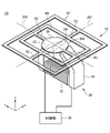
- FIG. 1 to 3 are diagrams illustrating the configuration of an actuator 10 according to an embodiment.
- 1 is a perspective view of the actuator 10
- FIG. 2 is a side view of the actuator 10
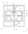
- FIG. 3 is a plan view of the actuator 10.
- the x-axis, y-axis and z-axis shown in each figure are three axes orthogonal to each other.
- An actuator 10 according to this embodiment includes a mirror 20 and an electromagnet 30 .
- a permanent magnet 21 is provided on the mirror 20 .
- the mirror 20 can swing with respect to the reference plane 101 with a first axis 201 and a second axis 202 as swing axes.
- the second axis 202 is non-parallel to the first axis 201 .
- Electromagnet 30 has yoke 34 and coil 32 and applies magnetic flux to permanent magnet 21 . Both ends (end portion 341 and end portion 342 ) of yoke 34 are at least partially opposed to each other with gap 340 interposed therebetween. The center Cg of the gap 340 does not overlap the center Cm of the permanent magnet 21 when viewed from the direction (z-axis direction) perpendicular to the reference plane 101 .
- a current I1 for swinging the mirror 20 about the first axis 201 and a current I2 for swinging the mirror 20 about the second axis 202 are superimposed and flowed through the coil 32. .
- to oscillate the mirror 20 about the first axis 201 is the same as to oscillate the mirror 20 about the first axis 201 , and to oscillate the mirror 20 about the second axis 202 .
- to oscillate means to oscillate the mirror 20 with the second axis 202 as the oscillation axis.
- the mirror 20 has a reflecting surface 22, and a permanent magnet 21 is fixed at the center of the surface opposite to the reflecting surface 22.
- a first pole 211 which is one pole of the permanent magnet 21, faces the mirror 20 side
- a second pole 212 which is the other pole, faces the opposite side of the mirror 20, that is, the side where the electromagnet 30 is provided.
- the reference plane 101 is a plane including the reflecting surface 22 of the mirror 20 in a reference state in which no current is flowing through the coils of the electromagnet 30, that is, in a reference state in which the permanent magnet 21 receives no force. 1 to 3 all show the reference state.
- a reference plane 101 is parallel to the xy plane.
- the actuator 10 is a biaxial actuator and can swing the mirror 20 about the first axis 201 and the second axis 202 . Thereby, the direction of the light reflected by the reflecting surface 22 of the mirror 20 can be changed two-dimensionally.
- the first axis 201 and the second axis 202 are substantially orthogonal or orthogonal.
- the coil 32 is wound around at least part of the yoke 34.
- a magnetic flux is generated between the ends 341 and 342 by the current flowing through the coil 32 .
- the mirror 20 can be oscillated about the first axis 201 and the second axis 202 .
- the same electromagnet 30 is used to drive the mirror 20 along the first axis 201 and the second axis 202 . That is, the electromagnet for swinging the mirror 20 about the first axis 201 and the electromagnet for swinging the mirror 20 about the second axis 202 are not separated. By doing so, it is possible to reduce the size of the actuator 10 without providing an electromagnet for each of the plurality of swing axes.
- the electromagnet 30 is U-shaped or C-shaped. Specifically, both ends (end portion 341 and end portion 342 ) of yoke 34 of electromagnet 30 face each other with at least part of permanent magnet 21 interposed therebetween when viewed from the direction perpendicular to reference plane 101 . Both ends 341 and 342 are magnetic flux generating ends.
- the electromagnet 30 may be composed of a plurality of electromagnets configured so that at least a part of the magnetic flux generating end faces each other with a gap 340 interposed therebetween. That is, the yoke 34 and the coil 32 of the electromagnet 30 may be divided into a plurality of parts. In the example of FIGS. 1-3, ends 341 and 342 are closer to mirror 20 than coil 32 is. Also, the coil 32 extends in a direction parallel to the reference plane 101 .
- FIG. Actuator 10 further comprises outer frame 50 , torsion bars 52 , inner frame 60 and torsion bars 62 .
- the outer frame 50 and inner frame 60 are connected via two torsion bars 52 .
- the inner frame 60 and mirror 20 are connected via two torsion bars 62 .
- Outer frame 50, torsion bar 52, inner frame 60, torsion bar 62, and mirror 20 are integrally formed by, for example, microfabrication of a semiconductor wafer, and actuator 10 is a MEMS actuator.
- electromagnet 30 is located entirely on one side of structure 12 including outer frame 50 , torsion bar 52 , inner frame 60 , torsion bar 62 and mirror 20 .
- the outer frame 50 is fixed to the housing (not shown) of the actuator 10.
- the inner frame 60 can swing with respect to the outer frame 50 with the first shaft 201 as a swing axis.
- Two torsion bars 52 coincide with the first axis 201 . That is, the two torsion bars 52 overlap along the first axis 201 , and the inner frame 60 swings with respect to the outer frame 50 as the torsion bars 52 twist.
- the mirror 20 can swing with respect to the inner frame 60 with the second axis 202 as a swing axis.
- Two torsion bars 62 coincide with the second axis 202 .
- the two torsion bars 62 overlap along the second axis 202 , and the mirror 20 swings with respect to the inner frame 60 as the torsion bars 62 twist.
- the torsion bars 52 and 62 are not twisted, and one surface of the outer frame 50 , the inner frame 60 and the mirror 20 are positioned on the same plane as the reference plane 101 .
- FIG. 1 Driving the actuator 10 by the electromagnet 30 will now be described with reference to FIGS. 1 to 3, 5 and 6.
- FIG. First driving with the first shaft 201 as the swing axis will be described.
- current flows through the coil 32 of the electromagnet 30 .
- magnetic flux is generated between the ends 341 and 342 .
- the ends 341 and 342 have different poles.
- the direction of the mirror 20 is changed so that the permanent magnet 21 is directed toward the end portion 341 and the end portion 342 that has a different pole from the second pole 212 .
- the orientation of the mirror 20 changes each time the polarity of the current changes from positive to negative and vice versa.
- the end portion 341 and the end portion 342 have end faces perpendicular to the second axis 202 .
- the ends 341 and 342 of the yoke 34 face each other in the direction parallel to the second axis 202 (y-axis direction). By doing so, it is possible to reduce crosstalk between the rocking movement about the first axis 201 and the rocking movement about the second axis 202 .
- the yoke 34 may be arranged so that both ends obliquely face the second shaft 202 .
- the end portion 341 and the end portion 342 may have end faces perpendicular to the first axis 201 .
- the ends 341 and 342 of the yoke 34 may face each other in the direction parallel to the first axis 201 (x-axis direction).
- the yoke 34 may be arranged so that both ends obliquely face the first shaft 201 .
- the vibration is generated due to driving with the second axis 202 as the swing axis.
- the torque that can be generated is smaller than the torque that can be generated for driving with the first shaft 201 as the swing axis.
- the mirror 20 is driven to oscillate at the resonance frequency with respect to the second axis 202 . Therefore, it is possible to sufficiently swing the mirror 20 even with a relatively small driving torque.
- the center Cg of the gap 340 does not overlap the center Cm of the permanent magnet 21 when viewed from the direction (z-axis direction) perpendicular to the reference plane 101 .
- the center of the gap 340 is displaced from the center of the permanent magnet 21 in the direction parallel to the first axis 201 (x-axis direction). By doing so, it is possible to increase the torque for swinging the mirror 20 with the second axis 202 as the swing axis.
- the center of the gap 340 is not displaced from the center of the permanent magnet 21 in the direction perpendicular to the first axis 201 (y-axis direction). By doing so, it is possible to reduce crosstalk between the rocking movement about the first axis 201 and the rocking movement about the second axis 202 .
- the gap 340 may be shifted diagonally from the center of the permanent magnet 21 with respect to the first axis 201 or may be shifted diagonally with respect to the second axis 202 .
- the actuator 10 further includes a control section 70 .
- the control unit 70 generates a signal in which the current I1 for oscillating the mirror 20 about the first axis 201 and the current I2 for oscillating it about the second axis 202 are superimposed.
- Control unit 70 includes, for example, drive circuit 72 and integrated circuit 40 .
- FIG. 4 is a diagram illustrating the hardware configuration of the control unit 70. As shown in FIG. In this figure, the controller 70 is implemented using the integrated circuit 40 .
- the integrated circuit 40 is, for example, an SoC (System On Chip).
- the control unit 70 includes an integrated circuit 40 and a drive circuit 72 .
- the integrated circuit 40 has a bus 402 , a processor 404 , a memory 406 , a storage device 408 , an input/output interface 410 and a network interface 412 .
- the bus 402 is a data transmission path through which the processor 404, memory 406, storage device 408, input/output interface 410, and network interface 412 exchange data with each other.
- the method of connecting the processors 404 and the like to each other is not limited to bus connection.
- the processor 404 is an arithmetic processing device implemented using a microprocessor or the like.
- the memory 406 is a memory implemented using a RAM (Random Access Memory) or the like.
- the storage device 408 is a storage device implemented using a ROM (Read Only Memory), flash memory, or the like.
- the input/output interface 410 is an interface for connecting the integrated circuit 40 with peripheral devices.
- at least the drive circuit 72 is connected to the input/output interface 410 .
- a network interface 412 is an interface for connecting the integrated circuit 40 to a communication network.
- This communication network is, for example, a CAN (Controller Area Network) communication network.
- a method for connecting the network interface 412 to the communication network may be a wireless connection or a wired connection.
- the storage device 408 stores program modules for realizing the functions of the control unit 70 respectively.
- the processor 404 implements the functions of the control unit 70 by reading this program module into the memory 406 and executing it.
- the hardware configuration of the integrated circuit 40 is not limited to the configuration shown in this figure.
- program modules may be stored in memory 406 .
- integrated circuit 40 may not include storage device 408 .
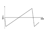
- FIG. 5 is a diagram illustrating the waveform of the current I1 for swinging the mirror 20 about the first axis 201.
- FIG. 6 is a diagram illustrating the waveform of the current I2 for swinging the mirror 20 about the second axis 202.
- FIG. 7 shows the current (I 1 +I 2 ) obtained by superimposing the current for oscillating the mirror 20 about the first axis 201 and the current for oscillating it about the second axis 202 .
- FIG. 4 is a diagram illustrating waveforms;
- Current I1 for oscillating mirror 20 about first axis 201 is, for example, a sawtooth wave or a triangular wave.
- Current I2 for oscillating mirror 20 about second axis 202 is, for example, a sine wave.
- the mirror 20 is driven to oscillate about the second axis 202 at the resonant frequency.
- a drive current (I 1 +I 2 ) in which the currents I 1 and I 2 are superimposed is generated by the control unit 70 described above, and the drive current is supplied from the control unit 70 to the coil 32 .
- the driving current as shown in FIG. 7, the mirror 20 can be driven so that the light reflected by the reflecting surface 22 performs raster scanning.
- the waveforms of current I1 and current I2 are not limited to the examples shown in FIGS. 5 and 6, respectively.
- the center Cg of the gap 340 does not overlap the center Cm of the permanent magnet 21 when viewed from the direction perpendicular to the reference plane 101 . Therefore, the same electromagnet 30 can be used to drive the mirror 20 along the first axis 201 and the second axis 202 . As a result, the actuator 10 can be miniaturized.
- FIG. 8 is a graph showing the result of simulating the relationship between the position of the electromagnet 30 and the generated torque.
- the simulation was performed by changing the distance between the permanent magnet 21 and the yoke 34 to a plurality of values (the unit in FIG. 8 is mm) in the z direction.
- the horizontal axis of the graph is the distance (offset) between the center Cg of the gap 340 and the center Cm of the permanent magnet 21 as seen from the z-axis direction.
- the vertical axis of the graph is the magnitude of the torque generated by the electromagnet 30 that swings the mirror 20 about the second axis 202 .
- FIG. 9 is a graph showing the results of measuring the relationship between the position of the electromagnet 30 and the amplitude of the mirror.
- the mirror 20 was oscillated about the second axis 202 and the oscillation amplitude was measured. Measurements were made for multiple offset values, and the drive signal was the same sine wave. When the offset is 2.5 mm, as shown in this figure. It was possible to oscillate up to nearly 60° in terms of optical oscillation angle.
Landscapes
- Physics & Mathematics (AREA)
- General Physics & Mathematics (AREA)
- Optics & Photonics (AREA)
- Electromagnetism (AREA)
- Mechanical Optical Scanning Systems (AREA)
- Mechanical Light Control Or Optical Switches (AREA)
Abstract
Description
永久磁石が設けられ、基準面に対し、第1の軸と前記第1の軸に非平行な第2の軸とをそれぞれ揺動軸として揺動可能なミラーと、
ヨークおよびコイルを有し、前記永久磁石に磁束を作用させる電磁石とを備え、
前記ヨークの両端はギャップを挟んで少なくとも一部が互いに対向しており、
前記基準面に垂直な方向から見て、前記ギャップの中心は前記永久磁石の中心とは重ならず、
前記コイルには、前記ミラーを、前記第1の軸に対して揺動させるための電流と前記第2の軸に対して揺動させるための電流とが重畳されて流される
アクチュエーターである。
図1~図3は、実施形態に係るアクチュエーター10の構成を例示する図である。図1はアクチュエーター10の斜視図であり、図2はアクチュエーター10の側面図であり、図3はアクチュエーター10の平面図である。各図に示されたx軸、y軸およびz軸は互いに直交する三軸である。本実施形態に係るアクチュエーター10は、ミラー20と電磁石30とを備える。ミラー20には永久磁石21が設けられている。ミラー20は、基準面101に対し、第1の軸201と第2の軸202とをそれぞれ揺動軸として揺動可能である。第2の軸202は第1の軸201とは非平行である。電磁石30は、ヨーク34およびコイル32を有し、永久磁石21に磁束を作用させる。ヨーク34の両端(端部341および端部342)はギャップ340を挟んで少なくとも一部が互いに対向している。基準面101に垂直な方向(z軸方向)から見て、ギャップ340の中心Cgは永久磁石21の中心Cmとは重ならない。そしてコイル32には、ミラー20を、第1の軸201に対して揺動させるための電流I1と第2の軸202に対して揺動させるための電流I2とが重畳されて流される。以下に詳しく説明する。
12 構造体
20 ミラー
21 永久磁石
22 反射面
30 電磁石
32 コイル
34 ヨーク
40 集積回路
50 外側フレーム
52 トーションバー
60 内側フレーム
62 トーションバー
70 制御部
72 駆動回路
101 基準面
201 第1の軸
202 第2の軸
340 ギャップ
341 端部
342 端部
Claims (6)
- 永久磁石が設けられ、基準面に対し、第1の軸と前記第1の軸に非平行な第2の軸とをそれぞれ揺動軸として揺動可能なミラーと、
ヨークおよびコイルを有し、前記永久磁石に磁束を作用させる電磁石とを備え、
前記ヨークの両端はギャップを挟んで少なくとも一部が互いに対向しており、
前記基準面に垂直な方向から見て、前記ギャップの中心は前記永久磁石の中心とは重ならず、
前記コイルには、前記ミラーを、前記第1の軸に対して揺動させるための電流と前記第2の軸に対して揺動させるための電流とが重畳されて流される
アクチュエーター。 - 請求項1に記載のアクチュエーターにおいて、
前記ミラーは、前記第2の軸に対して共振周波数で揺動するよう駆動され、
前記ヨークの両端は、互いに前記第2の軸に平行な方向に対向する
アクチュエーター。 - 請求項1または2に記載のアクチュエーターにおいて、
前記基準面に垂直な方向から見て、前記ギャップの中心は、前記永久磁石の中心から前記第1の軸に平行な方向にずれている
アクチュエーター。 - 請求項1~3のいずれか一項に記載のアクチュエーターにおいて、
前記ミラーを、前記第1の軸に対して揺動させるための電流はノコギリ波または三角波であり、
前記ミラーを、前記第2の軸に対して揺動させるための電流は正弦波である
アクチュエーター。 - 請求項1~4のいずれか一項に記載のアクチュエーターにおいて、
前記第1の軸に対して揺動させるための電流と前記第2の軸に対して揺動させるための電流とが重畳された信号を生成する制御部をさらに有する
アクチュエーター。 - 請求項1~5のいずれか一項に記載のアクチュエーターにおいて、
MEMSアクチュエーターである
アクチュエーター。
Priority Applications (4)
| Application Number | Priority Date | Filing Date | Title |
|---|---|---|---|
| CN202280018754.2A CN116964506A (zh) | 2021-03-02 | 2022-03-01 | 促动器 |
| US18/278,596 US20240126069A1 (en) | 2021-03-02 | 2022-03-01 | Actuator |
| EP22763233.8A EP4303640A1 (en) | 2021-03-02 | 2022-03-01 | Actuator |
| JP2023503849A JPWO2022186178A1 (ja) | 2021-03-02 | 2022-03-01 |
Applications Claiming Priority (2)
| Application Number | Priority Date | Filing Date | Title |
|---|---|---|---|
| JP2021-032420 | 2021-03-02 | ||
| JP2021032420 | 2021-03-02 |
Publications (1)
| Publication Number | Publication Date |
|---|---|
| WO2022186178A1 true WO2022186178A1 (ja) | 2022-09-09 |
Family
ID=83154770
Family Applications (1)
| Application Number | Title | Priority Date | Filing Date |
|---|---|---|---|
| PCT/JP2022/008511 WO2022186178A1 (ja) | 2021-03-02 | 2022-03-01 | アクチュエーター |
Country Status (5)
| Country | Link |
|---|---|
| US (1) | US20240126069A1 (ja) |
| EP (1) | EP4303640A1 (ja) |
| JP (1) | JPWO2022186178A1 (ja) |
| CN (1) | CN116964506A (ja) |
| WO (1) | WO2022186178A1 (ja) |
Citations (5)
| Publication number | Priority date | Publication date | Assignee | Title |
|---|---|---|---|---|
| JP2009069676A (ja) | 2007-09-14 | 2009-04-02 | Ricoh Co Ltd | 光走査装置 |
| JP2016092508A (ja) * | 2014-10-31 | 2016-05-23 | セイコーエプソン株式会社 | 画像表示装置 |
| WO2019172307A1 (ja) * | 2018-03-09 | 2019-09-12 | パイオニア株式会社 | アクチュエータ付き反射板、光走査装置、及びミラーアクチュエータ |
| JP2021032420A (ja) | 2019-08-14 | 2021-03-01 | 三菱パワー株式会社 | 貫流ボイラの制御装置、発電プラント、及び、貫流ボイラの制御方法 |
| JP2021033087A (ja) * | 2019-08-26 | 2021-03-01 | パイオニア株式会社 | ミラースキャナ |
-
2022
- 2022-03-01 US US18/278,596 patent/US20240126069A1/en active Pending
- 2022-03-01 JP JP2023503849A patent/JPWO2022186178A1/ja active Pending
- 2022-03-01 EP EP22763233.8A patent/EP4303640A1/en active Pending
- 2022-03-01 WO PCT/JP2022/008511 patent/WO2022186178A1/ja active Application Filing
- 2022-03-01 CN CN202280018754.2A patent/CN116964506A/zh active Pending
Patent Citations (5)
| Publication number | Priority date | Publication date | Assignee | Title |
|---|---|---|---|---|
| JP2009069676A (ja) | 2007-09-14 | 2009-04-02 | Ricoh Co Ltd | 光走査装置 |
| JP2016092508A (ja) * | 2014-10-31 | 2016-05-23 | セイコーエプソン株式会社 | 画像表示装置 |
| WO2019172307A1 (ja) * | 2018-03-09 | 2019-09-12 | パイオニア株式会社 | アクチュエータ付き反射板、光走査装置、及びミラーアクチュエータ |
| JP2021032420A (ja) | 2019-08-14 | 2021-03-01 | 三菱パワー株式会社 | 貫流ボイラの制御装置、発電プラント、及び、貫流ボイラの制御方法 |
| JP2021033087A (ja) * | 2019-08-26 | 2021-03-01 | パイオニア株式会社 | ミラースキャナ |
Also Published As
| Publication number | Publication date |
|---|---|
| JPWO2022186178A1 (ja) | 2022-09-09 |
| US20240126069A1 (en) | 2024-04-18 |
| EP4303640A1 (en) | 2024-01-10 |
| CN116964506A (zh) | 2023-10-27 |
Similar Documents
| Publication | Publication Date | Title |
|---|---|---|
| JP2005173411A (ja) | 光偏向器 | |
| CN104570333B (zh) | 光扫描仪、图像显示装置、头戴式显示器以及平视显示器 | |
| US20070268099A1 (en) | Actuator and two-dimensional scanner | |
| EP3006395B1 (en) | Drive device | |
| WO2013168264A1 (ja) | 駆動装置 | |
| US9772490B2 (en) | Optical scanner, image display device, head mount display, and heads-up display | |
| US20140118809A1 (en) | Optical scanning device, image display apparatus and optical scanning method | |
| US11555892B2 (en) | Drive device and distance measurement apparatus | |
| WO2022186178A1 (ja) | アクチュエーター | |
| JP2007094109A (ja) | 光スキャナ | |
| WO2022180822A1 (ja) | アクチュエーター | |
| JP2004237400A (ja) | プレーナー型アクチュエータ | |
| JP2008058434A (ja) | 揺動装置、揺動装置を用いた光偏向装置、及び光偏向装置を用いた画像形成装置 | |
| WO2013168273A1 (ja) | 駆動装置 | |
| JP2021033087A (ja) | ミラースキャナ | |
| JP2021162650A (ja) | ミラースキャナ | |
| JP7386671B2 (ja) | 駆動装置及び駆動方法 | |
| WO2021100803A1 (ja) | ミラースキャナ | |
| US11340446B2 (en) | Actuator | |
| JP5624213B2 (ja) | 駆動装置 | |
| WO2013168275A1 (ja) | 駆動装置 | |
| US20060119961A1 (en) | Driving X and Y mirrors with minimum electrical feeds | |
| WO2013168269A1 (ja) | 駆動装置 | |
| KR20240046229A (ko) | 반사체 스캐너 | |
| JP2023097199A (ja) | 走査用ミラー装置 |
Legal Events
| Date | Code | Title | Description |
|---|---|---|---|
| 121 | Ep: the epo has been informed by wipo that ep was designated in this application |
Ref document number: 22763233 Country of ref document: EP Kind code of ref document: A1 |
|
| WWE | Wipo information: entry into national phase |
Ref document number: 18278596 Country of ref document: US |
|
| WWE | Wipo information: entry into national phase |
Ref document number: 2023503849 Country of ref document: JP |
|
| WWE | Wipo information: entry into national phase |
Ref document number: 202280018754.2 Country of ref document: CN |
|
| WWE | Wipo information: entry into national phase |
Ref document number: 2022763233 Country of ref document: EP |
|
| NENP | Non-entry into the national phase |
Ref country code: DE |
|
| ENP | Entry into the national phase |
Ref document number: 2022763233 Country of ref document: EP Effective date: 20231002 |